

Page 1

X-Rite® 882
(An Addendum to the X-Rite 881 Operation Manual)
The X-Rite 882 was designed to meet the quality control needs of the professional
photofinisher processing E-6, as well as the other common processes.
The 882 is very much like the X-Rite 881, except that the 881 has only Status M for
transmission operation, and the 882 has Status A and M for transmission operation.
Transmission Status A is used for checking Positive transparencies (i.e., E-6 films) and
Status M for checking Negative transparencies (i.e., C41 negatives). The 881 Operation
Manual explains all of the functions and operation of the 882. However, there are a few
differences in operation and they are explained in this 882 addendum.
The 882 has the additional capability of:
•Measuring E-6 (Kodak & Fuji), Q-Lab, AP44, and P-5 film strips
•Measuring 2 different types of Internegatives
The additional film strips are selected and measured in the same manner as the other
film strips explained in the 881 Operation Manual. The procedure for selecting and
measuring internegative strips is explained in Section 1 of this addendum. Refer to
Section 2 for definition on the additional film strips and internegatives.
The following are registered trademarks: Kodak; Fuji; Agfa; Ilford
All products mentioned are trademarks of their respective companies.
P/N 882-500 Rev. F-07/16/93
Page 2
1. Measuring an Internegative
The 882 allows measurements of internegatives. It will optional compute the changes in exposure
and filter pack necessary to balance the internegative using the Density Difference method.
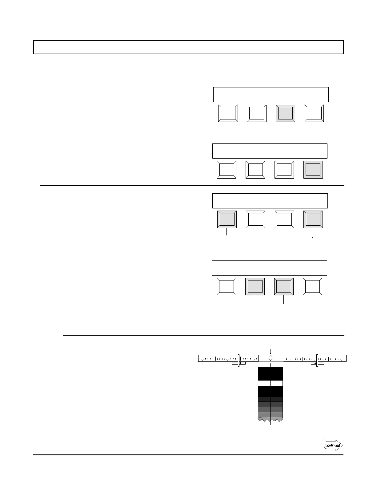
Step 1 - Press [film].
Step 2 - Press [other] until "Ineg Step 1" is
displayed.
Step 3 - Select the interneg type (see Section 2
for type definition).
Each depression of the [type] key will
alternate between "type 1" and "type 2"
(for this example "type 2" is selected).
Step 4 - Select interneg film type.
CHANNEL MENU
p1 pap film pbM
Process Type
READ
Typ 1 other
READ
Typ 2
Interneg
Selection
READ
Typ 2
Ineg Step 1
6011
Ineg Step 1
6011
Ineg Step 1
4114
other
Other
Film Strips
other
Press either center key to select the film
type. Select "6011" if you are using film
similar to Kodak 6011 or 4112 Interneg
film. Select "4114" if you are using film
similar to Kodak 4114.
Step 5 - Insert strip into the 35mm slot (step 1
inserted first) until it rests against the
drive rollers.
Film Type
Selection
35mm SLOT
30
20 3010
10
20
1
Page 3
Measuring an Internegative - continued
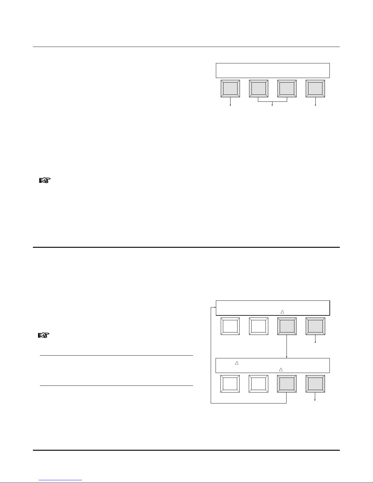
Step 6 - When the reading is completed, the
display will indicate which step pair will be
used on subsequent calculations.
•Pressing the [view] key allows viewing
of density difference numbers (refer to
Section 1.1).
•Pressing the [+Step-] key allows
viewing of the individual steps on the
strip (refer to Section 1.2)
•Pressing the [auto] key performs filter
pack and exposure calculations
automatically (refer to Section 1.3).
› If the strip is severely over exposed, the warning message
"STRIP TOO FAR OVEREXPOSED" will appear briefly. You will
then be allowed to view the individual steps using [+] or [-]
step keys, but will not be able to use the view and auto
functions. If this happens, reduce your exposure by three or
four stops and try another strip.
1.1 View (continued from Step 5 in Section 1)
STEP PAIR
view + step - auto
See Section 1.1 See Section 1.2 See Section 1.3
= 3, 13
The View function allows you to view the density difference values and recommended
filter pack changes. Density difference values are calculated by simply subtracting the
density values of the higher numbered step from the densities of the lower numbered
step. These are used to look up your filter pack changes from the table.
Step 6 - Press [∆fp] key to get the filter pack
changes from the internal table and
D = 0.62
0.75 0.80
fp exit
display them.
› These numbers are changes (indicated by the Greek letter
∆) and should be added to the filter pack which was used
for exposing this internegative.
Step 7 - Press [∆den] key to display the density
FP -03C
+05M +02Y
den exit
difference values again.
Step 8 - Press [exit] to return to the Step Pair
Menu so that further viewing or
calculations can be performed.
To Step Pair Menu
To Step Pair Menu
2
Page 4
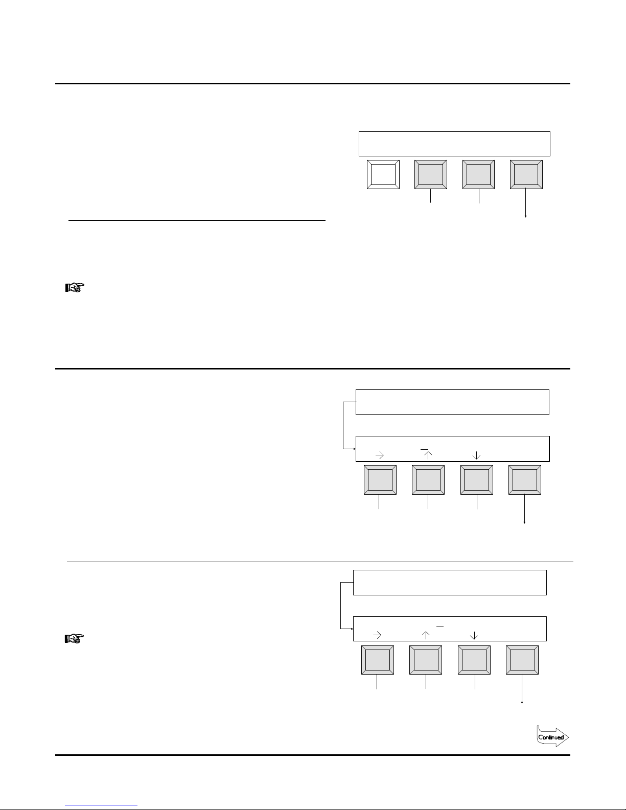
1.2 +Step- (continued from Step 5 in Section 1)
The +Step- function allows viewing of the individual steps on the strip.
Step 6 - Press either the [+] or [-] key to view
data on each step of the internegative.
•[+] increments to the next step (step 21 will
advance to step 1).
•[-] decrements to the next step (step 1 will
advance to step 21).
Step 7 - Press [exit] to return to the Step Pair
Menu so that further viewing or
calculations can be performed.
› For "Type 1" internegatives (4 x 5 format), all of the even
numbered steps are computed internally using a curve
fitting algorithm because the actual internegative contains
only the odd numbered steps.
1.3 Auto (continued from Step 5 Section 1)
0.20
0.47 0.83
+ step - exit#21
Next
Step
Previous
Step
To Step
Pair Menu
The Auto function initiates the automatic
exposure and filter pack compensation.
Step 6 - "Enter Starting Filter Pack..." is
momentarily displayed. Enter the values
of the filter pack used to make this
internegative.
•[↑] increases the value marked by cursor.
•[↓] decreases the value marked by cursor.
•[→] moves the cursor to the next position.
Press [cont] when finished.
Step 7 - "Enter Exposure" is momentarily
displayed. Enter your exposure time and
aperture.
› The "f" stop values increase or decrease in 1/6 stop steps
and values can range from f/4.0 to f/32.0.
•[↑] increases the value marked by cursor.
Moves
Cursor
Enter Starting
Filter Pack . . .
FP
EXP
00C
Enter Exposure
10 sec
30M 30Y
DecreasesIncreases
f/8.0
cont
To Next
Step
cont
•[↓] decreases the value marked by cursor.
•[→] moves the cursor to the next position.
Press [cont] when finished.
Moves
Cursor
DecreasesIncreases
To Next
Step
3
Page 5

Auto - continued
Step 8 - The display now indicates suggested
changes to your filter pack.
› The numbers displayed are changes (indicated by "∆")
and should be added to the filter pack which was used to
expose this internegative.
Press [∆off] to turn the "change mode"
off and view "absolute" filter pack values.
Absolute values are the addition of your
starting filter pack (entered earlier) to
the changed values.
› These values are adjusted to remove any neutral density.
Therefore, one of these values (usually cyan) will always
be zero. These values constitute your new filter pack
which should be used for subsequent exposures.
Step 9 - Press [exp] to display the suggested
exposure.
› Any neutral density adjustments to the filter pack will
affect exposure as well. To avoid reciprocity problems,
exposure time is held within 1/2 stop of your starting
exposure time. This will sometimes cause an aperture
change if the calculated exposure time adjustment is
greater than 1/2 stop.
FP
-03C +05M +02Y
off
FP 00C 39M 36Y
on
FP 00C 39M 36Y
on
exp
read
readexp
readexp
Step 10 - Press the [read] key to measure another
internegative. The entire procedure
described is repeated except that the
exposure and filter pack values you have
just viewed will be used as the starting
values.
Step 11 - Press the two keys labeled "MENU" to
exit out of the interneg function.
› Since internegatives are a setup tool rather than a process
control tool, any internegatives read are not stored in
channel memory. Data that is currently stored in the
channel memory is not destroyed.
EXP 11 sec f/8.0
READ
Typ 2
Ineg Step 1
4114
Displays
Filter
Pack
readfp
MENU
4
Page 6

2. Film Strip Definition
2.1 Positive Film Strips
•E-6 (Kodak)
5-1/4" Strip
Format: k:E-6 Process: E-6 Densitometry: Transmission, Status A
Fields Measured Computed Values Transformation Rules Action Control Spread
Field #1 "D-min" D-min R1; G1; B1; ±.03 +.05 ---Field #2 "LoDen" SPEED R2; G2; B2; ±.08 ±.10 ---Field #3 "HiDen" COLOR R3; G3; B3; ±.12 ±.15 ---Field #4 "D-max" D-max R4; G4; B4; -- .20 -- .25 ----
NOTES:
1) Strips must have at least a 1-1/8" (28mm) leader before outside edge of first target, in order for first target to be detected (see Sec.2.1
in the Control Strip & Balance Print Format Guide).
2) -------------> Indicates strip pass direction.
3) Yel, Mag, and Cyn patches on the Kodak strip are not measured.
Limits
5
Page 7

Positive Film Strip - continued
•E-6 (Kodak) Used for Q-Lab
Format: q:E-6 Process: QLab Densitometry: Transmission, Status A
Fields Measured Computed Values Transformation Rules Action Control Spread
Field #1 "D-Min" D-Min R1; G1; B1; + .02 +.03 ---Field #2 "TD" TD R2; G2; B2; ±.03 ±.04 ---Field #3 "LD" LD R3; G3; B3; ±.04 ±.05 ---Field #4 "HD" HD R4; G4; B4; ±.06 ±.08 ---Field #5 "D-Max" D-Max R5; G5; B5; -- .10 -- .13 ---Field #6 LDSpr R3-G3; ; B3-G3; ---- ±.10 ----
NOTES:
1) Strips must have at least a 1-1/8" (28mm) leader before outside edge of first target, in order for first target to be detected (see Sec.2.1
in the Control Strip & Balance Print Format Guide).
2) -------------> Indicates strip pass direction.
Limits
•E-6 (Fuji)
Format: f:E-6 Process: E-6 Densitometry: Transmission, Status A
Fields Measured Computed Values Transformation Rules Action Control Spread
Field #1 "D-min" D-min R1; G1; B1; ±.03 +.05 ---Field #2 "LoDen" SPEED R2; G2; B2; ±.08 ±.10 ---Field #3 "HiDen" COLOR R3; G3; B3; ±.12 ±.15 ---Field #4 "D-max" D-max R4; G4; B4; -- .20 -- .25 ----
NOTES:
1) Strips must have at least a 1-1/8" (28mm) leader before outside edge of first target, in order for first target to be detected (see Sec.2.1
in the Control Strip & Balance Print Format Guide).
2) -------------> Indicates strip pass direction.
Limits
6
Page 8

Positive Film Strip - continued
•P-5 (Ilford)
Format: i:P-5 Process: P-5 Densitometry: Transmission, Status A
Fields Measured Computed Values Transformation Rules Action Control Spread
Field #1 "D-Min" D-min R1; G1; B1; ± .03 + .05 ---Field #2 "LD" LD R2; G2; B2; ± .08 ± .10 ---Field #3 "HD" HD R3; G3; B3; ± .12 ± .15 ---Field #4 "D-Max" D-max R4; G4; B4; -- .20 -- .25 ----
NOTES:
1) Strips must have at least a 1-1/8" (28mm) leader before outside edge of first target, in order for first target to be detected (see Sec.2.1
in the 881 Operation Manual).
2) -------------> Indicates strip pass direction.
3) Yel, Mag, Cyn, Red, Grn, and Blu patches are not measured.
Limits
•AP44 (Agfa)
Format: a:AP44 Process: AP44 Densitometry: Transmission, Status A
Fields Measured Computed Values Transformation Rules Action Control Spread
Field #1 "D-Min" D-Min R1; G1; B1; ---- +.05 ---Field #2 "LD" LD R2; G2; B2; ---- ±.10 .08
Field #3 "HD" HD R3; G3; B3; ---- ±.15 .13
Field #4 "D-Max" D-Max R4; G4; B4; ---- -- .20 ----
NOTES:
1) Strips must have at least a 1-1/8" (28mm) leader before outside edge of first target, in order for first target to be detected (see Sec.2.1
in the Control Strip & Balance Print ).
2) <-------------> Indicates that strip may be inserted in either direction.
3) Small color patches are not measured.
Limits
7
Page 9

Positive Film Strip - continued
•Q-Lab (Kodak)
Format: k:Q-LAB Process: QLab Densitometry: Transmission, Status A
Fields Measured Computed Values Transformation Rules Action Control Spread
Field #1 "D-Min" D-Min R1; G1; B1; +.02 +.03 ---Field #2 "TD" TD R2; G2; B2; ±.03 ±.04 ---Field #3 "LD" LD R3; G3; B3; ±.04 ±.05 ---Field #4 "HD" HD R4; G4; B4; ±.06 ±.08 ---Field #5 "D-Max" D-Max R5; G5; B5; -- .10 -- .13 ---Field #6 LDSpr R3-G3; ; B3-G3; ---- ±.10 ----
NOTES:
1) Strips must have at least a 1-1/8" (28mm) leader before outside edge of first target, in order for first target to be detected (see Sec.2.1
in the 881 Operation Manual).
2) -------------> Indicates strip pass direction.
Limits
8
Page 10

2.2 Internegative Film Strips
•Type 1 (4 x 5)
The "Type 1" interneg consists of a
Kodak Step Tablet No. 1A cut between
steps 11 and 13, with the two halves
mounted side by side in a slide frame (see
illustration). Make sure that the full
length of the steps 11 and 13 show (i.e.,
not covered by the inside edge of the slide
frame).
This slide is then projected on to a 4 x 5
interneg such that each step is 1/2" wide.
Step 11 and 13 should begin
approximately 1/4" in from the edge of the
interneg. Note: Steps 1 and 21 can go off
the other end during projection - this is
OK.
Step 13 Step 21
Some
Overlapping
Permissible
Step 11 Slide Frame
Step 1 Step 21
Step 1
1/2"
Approx. 1/4"
Resulting Interneg
9
Page 11

Type 1 (4 x 5) - continued
To Measure the Type 1 Strip:
30
20 3010
10
20
1) Center step 1 over diamond and insert
until it rests against the drive rollers.
2) Center step 21 over diamond and insert
until it rests against the drive rollers.
30
Step 1
20 3010
10
Pass 1
20
Step 21
Pass 2
10
Page 12

•Type 2 (35mm)
The Type 2 interneg consists of a Kodak
Step Tablet No. 3 contact printed onto
35mm internegative film. To enable the
resulting interneg to be recognized by the
882, a piece of opaque tape must be
placed over part of step 1 on the step
tablet as shown. The tape should be
placed such that 0.4" (approx. 3/8") of step
1 is still exposed adjacent to step 2.
To satisfy the leader requirements of the
882, a 1-1/8" leader should precede the
taped area on the resulting interneg.
Tape
0.4"
0.4"
Step 1
White
Step 2
Step 3
Step Tablet
This strip is inserted into the 35mm slot
with step 1 entering first.
35mm SLOT
20 10
Light stripe
caused by tape.
10
20
1-1/8" Leader
Step 1
Step 2
Resulting Interneg
11
Page 13

3. Densitometer Specifications
Transmission Process Control
Film Width . . . . . . . . . . . . . . . . . . . . . . . . . . . . . . . . . . 35mm fixed slot or 1.4 - 6.0 inch adjustable
Measurement Speed . . . . . . . . . . . . . . . . . . . . . . . . . . 1.3 inches/second
Spectral Response . . . . . . . . . . . . . . . . . . . . . . . . . . . . Status A & M
Density Range . . . . . . . . . . . . . . . . . . . . . . . . . . . . . . . 0 - 4.0D
Density Accuracy . . . . . . . . . . . . . . . . . . . . . . . . . . . . . +/- .02D (0-3.00D), +/- 1% (3.01-3.40D,
+/- 3% (3.41-4.00D)
Density Repeatability . . . . . . . . . . . . . . . . . . . . . . . . . +/- .01D (0-3.00D), +/- .02D (3.01-3.40D),
+/- 0.04D (3.41-4.00D)
Control Strip Measurement Area . . . . . . . . . . . . . . . 0.375" (length) x 0.5" (wide) minimum
Reflection (paper) Process Control and Printer Balance
Paper Width . . . . . . . . . . . . . . . . . . . . . . . . . . . . . . . . . 1.4 - 6.0 inches (adjustable slot)
Measurement Speed . . . . . . . . . . . . . . . . . . . . . . . . . . 1.3 inches/second
Control Strip Measurement Area . . . . . . . . . . . . . . . 0.375" (length) x 0.5" (wide) minimum
Printer Balance Measuring Area . . . . . . . . . . . . . . . .0.75" diameter minimum
Spectral Response . . . . . . . . . . . . . . . . . . . . . . . . . . . . Status A
Density Range . . . . . . . . . . . . . . . . . . . . . . . . . . . . . . . 0 - 2.5D
Density Accuracy . . . . . . . . . . . . . . . . . . . . . . . . . . . . . +/- .02D
Density Repeatability . . . . . . . . . . . . . . . . . . . . . . . . . +/- .01D
General Specifications
A.C. Adaptor (115VAC - P/N SE30-61) (230VAC - P/N SE30-62) . . . . . 12VDC @ 0.7amp
Dimensions . . . . . . . . . . . . . . . . . . . . . . . . . . . . . . . . . . 7.2" x 6.0" x 2.75"
(182.8mm x 152.4mm x 69.8mm)
Specification and design subject to change without notice.
12
 Loading...