

Page 1
INSTRUCTION MANUAL
Page 2

BEFORE YOU START
This is a high-competition, high-quality RC car intended for persons aged 16
years and older with previous experience building and operating RC model
racing cars. This is not a toy; it is a precision racing model. This model racing
car is not intended for use by beginners, inexperienced customers, or by
children without direct supervision of a responsible, knowledgeable adult. If
you do not fulfill these requirements, please return the kit in unused and
unassembled form back to the shop where you have purchased it.
Before building and operating your XRAY, YOU MUST read through all of the
operating instructions and instruction manual and fully understand them to
get the maximum enjoyment and prevent unnecessary damage.
CUSTOMER SUPPORT
We have made every effort to make these instructions as easy to understand as
possible. However, if you have any difficulties, problems, or questions, please do not
hesitate to contact the XRAY support team at info@teamxray.com. Also, please visit
our Web site at www.teamxray.com to find the latest updates, set-up information,
option parts, and many other goodies. We pride ourselves on taking excellent care
of our customers.
You can join thousands of XRAY fans and enthusiasts in our online community at:
www.teamxray.com
FAILURE TO FOLLOW THESE INSTRUCTIONS WILL BE CONSIDERED AS ABUSE AND/OR NEGLECT.
SAFETY PRECAUTIONS
Contains:
LEAD (CAS 7439-92-1) ANTIMONY (CAS 7440-36-0)
WARNING: This product contains a chemical known to the state of California
to cause cancer and birth defects or other reproductive harm.
CAUTION: CANCER HAZARD
Contains lead, a listed carcinogen. Lead is harmful if ingested. Wash
thoroughly after using. DO NOT use product while eating, drinking or using
tobacco products. May cause chronic effects to gastrointestinal tract, CNS,
kidneys, and blood. MAY CAUSE BIRTH DEFECTS.
When building, using and/or operating this model always wear protective
glasses and gloves.
Take appropriate safety precautions prior to operating this model. You are
responsible for this model‘s assembly and safe operation! Please read the
instruction manual before building and operating this model and follow all
safety precautions. Always keep the instruction manual at hand for quick
Read carefully and fully understand the instructions before beginning
assembly.
Make sure you review this entire manual, download and use set-up book from
the web, and examine all details carefully. If for some reason you decide this
is not what you wanted or expected, do not continue any further. Your hobby
dealer can not accept your kit for return or exchange after it has been partially
or fully assembled.
Contents of the box may differ from pictures. In line with our policy of
continuous product development, the exact specifications of the kit may vary
without prior notice.
XRAY Europe
K Vystavisku 6992
91101 Trenčín
Slovakia, EUROPE
Phone: 421-32-7401100
Fax: 421-32-7401109
E-mail: info@teamxray.com
reference, even after completing the assembly. Use only genuine and original
authentic XRAY parts for maximum performance. Using any third party parts
on this model will void guaranty immediately.
Improper operation may cause personal and/or property damage. XRAY
and its distributors have no control over damage resulting from shipping,
improper construction, or improper usage. XRAY assumes and accepts no
responsibility for personal and/or property damages resulting from the use
of improper building materials, equipment and operations. By purchasing
any item produced by XRAY, the buyer expressly warrants that he/she is in
compliance with all applicable federal, state and local laws and regulation
regarding the purchase, ownership and use of the item. The buyer expressly
agrees to indemnify and hold harmless XRAY for all claims resulting directly
or indirectly from the purchase, ownership or use of the product. By the act
of assembling or operating this product, the user accepts all resulting liability.
If the buyer is not prepared to accept this liability, then he/she should return
this kit in new, unassembled, and unused condition to the place of purchase.
XRAY USA
RC America, 2030 Century Center Blvd #15
Irving, TX 75062
USA
Phone: (214) 744-2400
Fax: (214) 744-2401
E-mail: xray@rcamerica.com
IMPORTANT NOTES – GENERAL
• This product is not suitable for children under 16 years of age without the
direct supervision of a responsible and knowledgeable adult.
• Carefully read all manufacturers warnings and cautions for any parts used
in the construction and use of your model.
• Assemble this kit only in places away from the reach of very small children.
• First-time builders and users should seek advice from people who have
building experience in order to assemble the model correctly and to allow
the model to reach its performance potential.
• Exercise care when using tools and sharp instruments.
• Take care when building, as some parts may have sharp edges.
• Keep small parts out of reach of small children. Children must not be
allowed to put any parts in their mouth, or pull vinyl bag over their head.
• Read and follow instructions supplied with paints and/or cement, if used
(not included in kit).
• Immediately after using your model, do NOT touch equipment on the
model such as the motor and speed controller, because they generate high
temperatures. You may seriously burn yourself seriously touching them.
• Follow the operating instructions for the radio equipment at all times.
• Do not put fingers or any objects inside rotating and moving parts, as this
may cause damage or serious injury as your finger, hair, clothes, etc. may
get caught.
• Be sure that your operating frequency is clear before turning on or running
your model, and never share the same frequency with somebody else at the
same time. Ensure that others are aware of the operating frequency you
are using and when you are using it.
• Use a transmitter designed for ground use with RC cars. Make sure that no
one else is using the same frequency as yours in your operating area. Using
the same frequency at the same time, whether it is driving, flying or sailing,
can cause loss of control of the RC model, resulting in a serious accident.
• Always turn on your transmitter before you turn on the receiver in the car.
Always turn off the receiver before turning your transmitter off.
• Keep the wheels of the model off the ground when checking the operation
of the radio equipment.
• Disconnect the battery pack before storing your model.
• When learning to operate your model, go to an area that has no obstacles
that can damage your model if your model suffers a collision.
• Remove any sand, mud, dirt, grass or water before putting your model
away.
• If the model behaves strangely, immediately stop the model, check and
clear the problem.
• To prevent any serious personal injury and/or damage to property, be
responsible when operating all remote controlled models.
• The model car is not intended for use on public places and roads or areas
where its operation can conflict with or disrupt pedestrian or vehicular traffic.
• Because the model car is controlled by radio, it is subject to radio
interference from many sources that are beyond your control. Since radio
interference can cause momentary loss of control, always allow a safety
margin in all directions around the model in order to prevent collisions.
• Do not use your model:
- Near real cars, animals, or people that are unaware that an RC car is being
driven.
- In places where children and people gather
- In residential districts and parks
- In limited indoor spaces
- In wet conditions
- In the street
- In areas where loud noises can disturb others, such as hospitals and
residential areas.
- At night or anytime your line of sight to the model may be obstructed or
impaired in any way.
To prevent any serious personal injury and/or damage to property, please be
responsible when operating all remote controlled models.
2
Page 3

IMPORTANT NOTES – ELECTRICAL
• Insulate any exposed electrical wiring (using heat shrink tubing or electrical
tape) to prevent dangerous short circuits. Take maximum care in wiring,
connecting and insulating cables. Make sure cables are always connected
securely. Check connectors for if they become loose. And if so, reconnect
them securely. Never use RC models with damaged wires. A damaged wire
is extremely dangerous, and can cause short-circuits resulting in fire. Please
have wires repaired at your local hobby shop.
• Low battery power will result in loss of control. Loss of control can occur due
to a weak battery in either the transmitter or the receiver. Weak running
battery may also result in an out of control car if your car‘s receiver power is
supplied by the running battery. Stop operation immediately if the car starts
to slow down.
• When not using RC model, always disconnect and remove battery.
• Do not disassemble battery or cut battery cables. If the running battery
short-circuits, approximately 300W of electricity can be discharged, leading
to fire or burns. Never disassemble battery or cut battery cables.
• Use a recommended charger for the receiver and transmitter batteries
and follow the instructions correctly. Over-charging, incorrect charging,
R/C & BUILDING TIPS
or using inferior chargers can cause the batteries to become dangerously
hot. Recharge battery when necessary. Continual recharging may damage
battery and, in the worst case, could build up heat leading to fire. If battery
becomes extremely hot during recharging, please ask your local hobby
shop for check and/or repair and/or replacement.
• Regularly check the charger for potential hazards such as damage to the
cable, plug, casing or other defects. Ensure that any damage is rectified
before using the charger again. Modifying the charger may cause shortcircuit or overcharging leading to a serious accident. Therefore do not
modify the charger.
• Always unplug charger when recharging is finished.
• Do not recharge battery while battery is still warm. After use, battery retains
heat. Wait until it cools down before charging.
• Do not allow any metal part to short circuit the receiver batteries or other
electrical/electronic device on the model.
• Immediately stop running if your RC model gets wet as may cause short
circuit.
• Please dispose of batteries responsibly. Never put batteries into fire.
• Make sure all fasteners are properly tightened. Check them periodically.
• Make sure that chassis screws do not protrude from the chassis.
• For the best performance, it is very important that great care is taken to
ensure the free movement of all parts.
• Clean all ball-bearings so they move very easily and freely.
• Tap or pre-thread the plastic parts when threading screws.
• Self-tapping screws cut threads into the parts when being tightened. Do
not use excessive force when tightening the self-tapping screws because
you may strip out the thread in the plastic. We recommended you stop
tightening a screw when you feel some resistance.
• Ask your local hobby shop for any advice.
WARRANTY
XRAY guarantees this model kit to be free from defects in both material and
workmanship within 30 days of purchase. The total monetary value under
warranty will in no case exceed the cost of the original kit purchased. This
warranty does not cover any components damaged by use or modification
or as a result of wear. Part or parts missing from this kit must be reported
within 30 days of purchase. No part or parts will be sent under warranty
without proof of purchase. Should you find a defective or missing part, contact
the local distributor. Service and customer support will be provided through
local hobby store where you have purchased the kit, therefore make sure to
purchase any XRAY products at your local hobby store. This model racing car
is considered to be a high-performance racing vehicle. As such this vehicle
will be used in an extreme range of conditions and situations, all which may
cause premature wear or failure of any component. XRAY has no control over
usage of vehicles once they leave the dealer, therefore XRAY can only offer
warranty against all manufacturer‘s defects in materials, workmanship, and
assembly at point of sale and before use. No warranties are expressed or
implied that cover damage caused by what is considered normal use, or cover
or imply how long any model cars‘ components or electronic components will
last before requiring replacement.
Due to the high performance level of this model car you will need to
periodically maintain and replace consumable components. Any and all
warranty coverage will not cover replacement of any part or component
damaged by neglect, abuse, or improper or unreasonable use. This includes
Please support your local hobby shop. We at XRAY Model Racing Cars support
all local hobby dealers. Therefore we ask you, if at all possible, to purchase
XRAY products at your hobby dealer and give them your support like we do.
If you have difficulty finding XRAY products, please check out www.teamxray.
com to get advice, or contact us via email at info@teamxray.com, or contact
the XRAY distributor in your country.
but is not limited to damage from crashing, chemical and/or water damage,
excessive moisture, improper or no maintenance, or user modifications which
compromise the integrity of components. Warranty will not cover components
that are considered consumable on RC vehicles. XRAY does not pay nor refund
shipping on any component sent to XRAY or its distributors for warranty. XRAY
reserves the right to make the final determination of the warranty status of
any component or part.
Limitations of Liability
XRAY makes no other warranties expressed or implied. XRAY shall not be liable
for any loss, injury or damages, whether direct, indirect, special, incidental,
or consequential, arising from the use, misuse, or abuse of this product and/
or any product or accessory required to operate this product. In no case shall
XRAY‘s liability excess the monetary value of this product.
Take adequate safety precautions prior to operating this model. You
are responsible for this model’s assembly and safe operation.
Disregard of the any of the above cautions may lead to accidents,
personal injury, or property damage. XRAY MODEL RACING CARS
assumes no responsibility for any injury, damage, or misuse of this
product during assembly or operation, nor any addictions that may
arise from the use of this product.
All rights reserved.
QUALITY CERTIFICATE
XRAY MODEL RACING CARS uses only the highest quality materials, the
best compounds for molded parts and the most sophisticated manufacturing
processes of TQM (Total Quality Management). We guarantee that all parts
of a newly-purchased kit are manufactured with the highest regard to quality.
However, due to the many factors inherent in model racecar competition, we
cannot guarantee any parts once you start racing the car. Products which have
been worn out, abused, neglected or improperly operated will not be covered
under warranty.
We wish you enjoyment of this high-quality and high-performance RC car and
wish you best success on the track!
In line with our policy of continuous product development, the exact specifications of the kit may
vary. In the unlikely event of any problems with your new kit, you should contact the model shop
where you purchased it, quoting the part number.
We do reserve all rights to change any specification without prior notice. All rights reserved.
3
Page 4
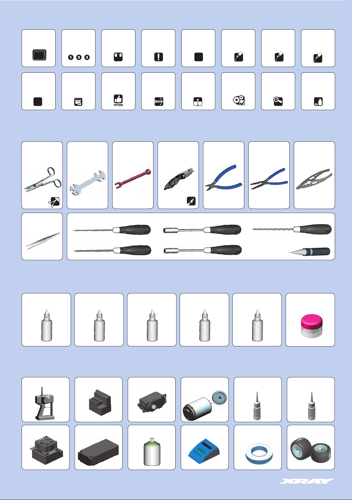
SYMBOLS USED
Part bags used Assemble left and
Assemble in the
specified order
right sides the
same way
05
Apply greaseScale Ensure smooth
Optional
1:1
TOOLS REQUIRED
Scissors
(HUDY #188990)
Special Tool for
turnbuckles & nuts
(HUDY #181090)
L=R
parts
Turnbuckle Wrench
3mm (HUDY #181030)
3.0 mm
Pay attention
here
non-binding
movement
Pocket Hobby Knife
Assemble as many
(HUDY #188981)
times as specified
(here twice)
2x
Tighten screw
gently
threadlock
Completed
assembly
Side Cutters
(HUDY #189010)
Apply
TL
Apply CA glue
Detail
DETAIL
Combination Pliers
(HUDY #189020)
Apply oil
CA
Professional Multi Tool
OIL
Apply cleaner
(HUDY #183011)
Tweezer
HUDY TOOLS:
Allen 1.5mm
Allen 2.0mm
Socket 5.5mm
Socket 7.0mm
Arm Reamer 3.0mm
Reamer (HUDY #107600) or (HUDY #107601)
ITEMS INCLUDED
HUDY Premium Silicone Oils HUDY Premium Silicone Oils HUDY Premium Silicone OilsHUDY Premium Silicone OilsHUDY Premium Silicone Oils Graphite Grease
Oil 450cSt (#106345) Oil 650cSt (#106365) Oil 100.000cSt (#106610)Oil 30.000cSt (#106530)Oil 10.000cSt (#106510)
(HUDY #106210)
EQUIPMENT REQUIRED
Transmitter Steering ServoReceiver
Electric Motor &
Pinion Gear with Set-screw
Bearing Oil
(HUDY #106230)
CA glue
Speed Controller LiPo Battery
4
Lexan™ Paint Battery Charger Tires & Inserts
Double-sided Tape
(HUDY #107875)
Page 5
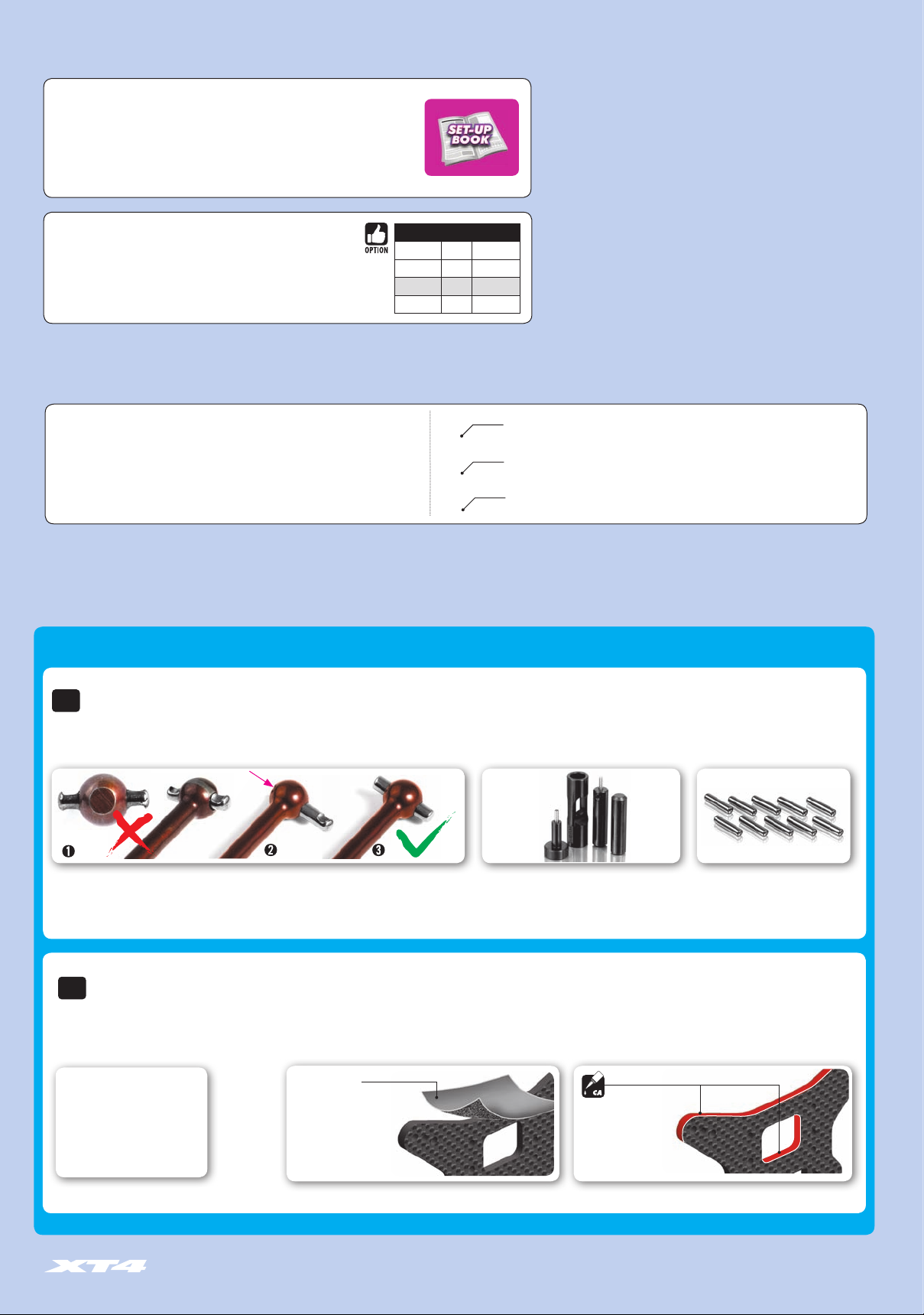
NOT INCLUDED
Set-up Book
To ensure that you always have access to the most up-to-date version of the HUDY Set-up
Book, you can download it from the HUDY website at [www.hudy.net]. By offering this
online version instead of including a hardcopy printed version in kits, you will always be
assured of having the most current updated version.
XRAY offers wide range of optional tuning parts which are listed in tables
like these. Please refer to the exploded view of each main section to verify
which part is included in the kit while all other parts are available only as an
optional part and must be purchased separately.
COLOR INDICATIONS
At the beginning of each section is an exploded view of the parts to be assembled.
There is also a list of all the parts and part numbers that are related to the assembly
of that section.
The part descriptions are color-coded to make it easier for you to identify the source
of a part. Here are what the different colors mean:
XB4 TECH TIPS
SAMPLE OF OPTIONAL PARTS
#32XXXX TYPE OPTION 1
#32XXXX TYPE OPTION 2
#32XXXX TYPE INCLUDED
#32XXXX TYPE OPTION 3
364910
361105
364902
STYLE A - indicates parts that are included in the bag marked for the section.
STYLE B - indicates parts that are included in the box.
STYLE C - indicates parts that are already assembled from previous steps.
TIP
DRIVE SHAFT PIN SERVICING
To enjoy the longest possible lifespan of the drive shafts and diff outdrives, it is extremely important to properly service the drive shaft pins.
Inspect the pins after every 3 hours of runtime. If the pins show any wear, replace them with new pins.
Do not use drive shafts
when the pins are worn.
TIP
GRAPHITE PARTS PREPARATION
Follow this Tech Tip to prepare the graphite parts. Sand the edges with sandpaper, and then seal the edges with CA glue to reinforce them and help prevent delamination.
Prepare all XT4 Graphite Parts:
• Front shock tower
• Rear shock tower
Press out the worn pins.
Press in new pins and
regularly inspect for wear.
Fine sandpaper
Use fine sandpaper to
sand smooth the edges of
all graphite parts.
For quick & easy drive pin replacements use
#106000 HUDY Drive Pin Replacement Tool
together with #106036 Ejector Pivot Pin &
Alternating Pivot 2.5mm.
Apply CA glue to all edges
of the graphite parts.
To replace the worn pins use only
premium HUDY drive pins
(#106051 3.0mm dia x 10mm lenght)
(#106053 2.5mm dia x 10mm lenght)
5
Page 6
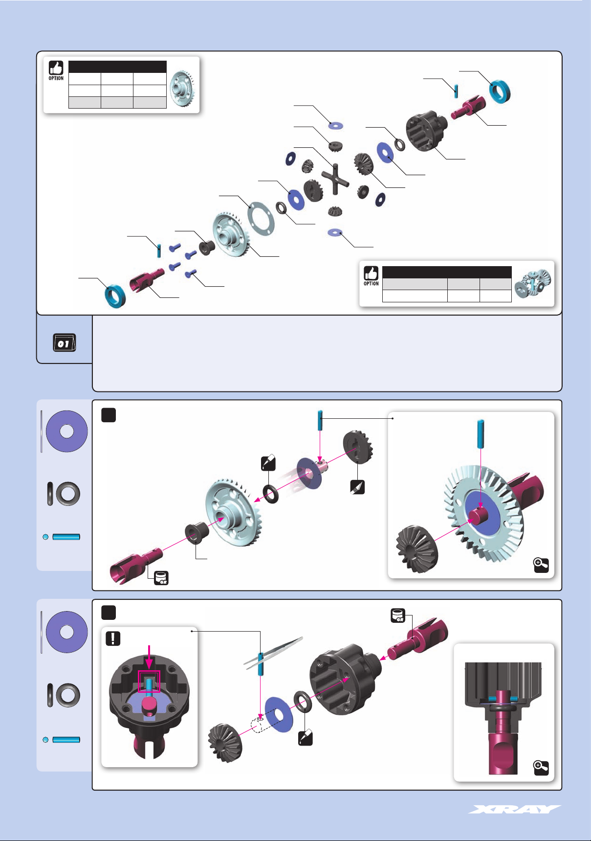
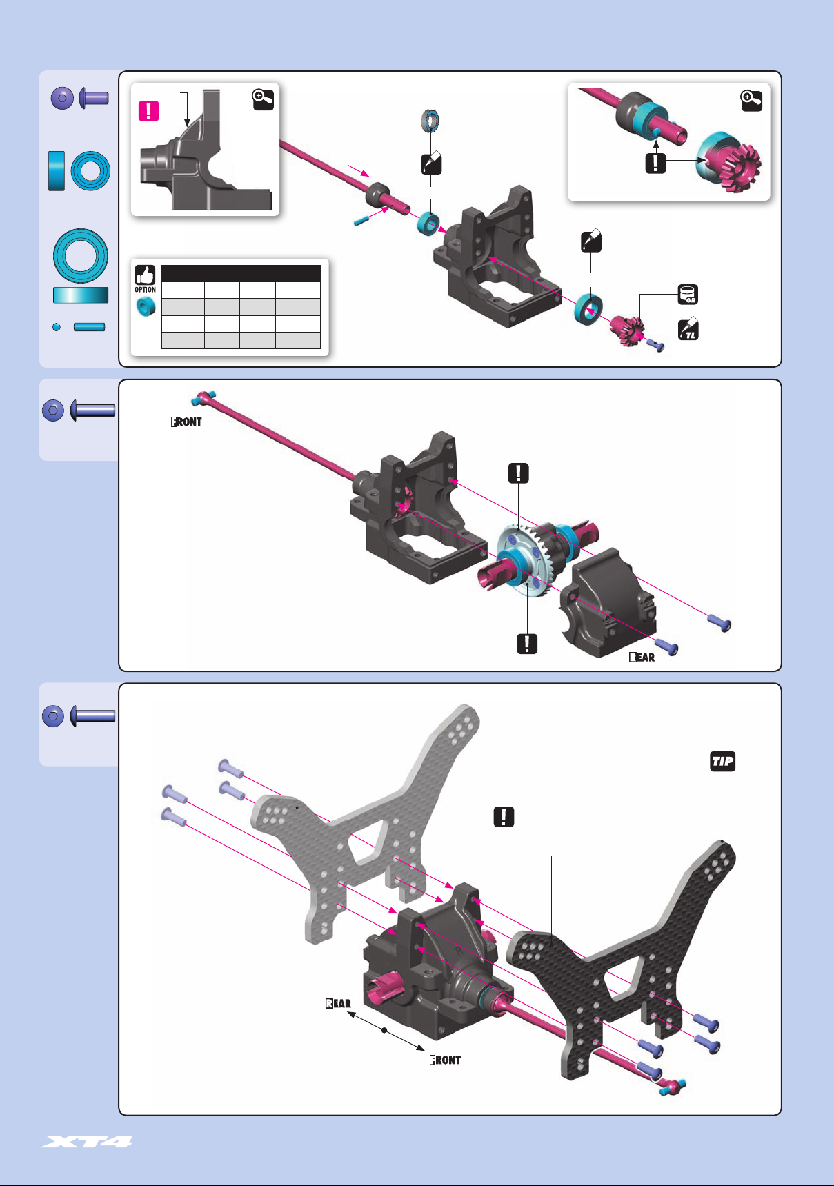
1. FRONT & REAR DIFFERENTIAL
BEVEL GEARS
#364935 GRAPHITE OPTION
#364945 ALU OPTION
#364955 STEEL INCLUDED
941014
BAG
304932 GRAPHITE GEAR DIFF BEVEL & SATELLITE GEARS (2+4)
304980 COMPOSITE GEAR DIFF CROSS PIN
304990 DIFF GASKET (4)
364902 GEAR DIFFERENTIAL FOR 2.5MM PIN - SET
364910 COMPOSITE GEAR DIFFERENTIAL CASE
364955 STEEL DIFFERENTIAL BEVEL GEAR 35T
364961 GEAR DIFF OUTDRIVE ADAPTER FOR 2.5MM PIN - HUDY SPRING STEEL™ (2)
981210
364961
364990
903258
304990
964050
364955
964031
304932
304980
972050
981210
972050
941014
364961
364910
964050
304932
964031
BEVEL & SATELITTE GEARS + PINS
#304932 + #304980 GRAPHITE INCLUDED
#335030 + #335080 STEEL OPTION
364990 COMPOSITE BEVEL GEAR BUSHING (2)
903258 HEX SCREW SFH M2.5x8 (10)
941014 BALL-BEARING 10x15x4 RUBBER SEALED - GREASE (2)
964031 WASHER S 3.5x10x0.2 (10)
964050 WASHER S 5x15x0.3 (10)
972050 SILICONE O-RING 5x2 (10)
981210 PIN 2x10 (10)
964050
S 5x15x0.3
972050
O 5x2
981210
P 2x10
964050
S 5x15x0.3
2x
2x
NOTE ORIENTATION
➊
#106210 HUDY GRAPHITE GREASE
➍
OIL
➌
➋
DO NOT USE for optional ALU or GRAPHITE gears
#106210 HUDY GRAPHITE GREASE
➍
STEP DETAIL
Use tweezers to
insert pin
➍
➋
➌
➍➎
➎
STEP DETAIL
➎
➊
➍
DETAIL
CUTAWAY VIEW
972050
O 5x2
981210
P 2x10
➎
OIL
DETAIL
6
Page 7
1. FRONT & REAR DIFFERENTIAL
964031
S 3.5x10x0.2
2x
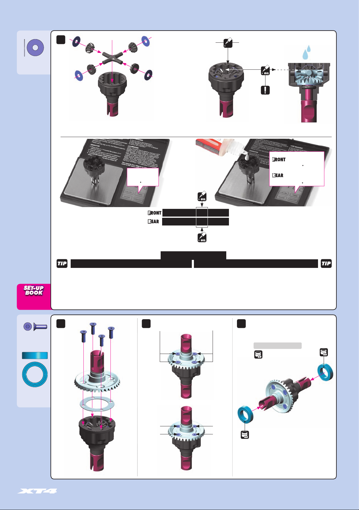
TO ENSURE YOU HAVE THE SAME AMOUNT OF OIL FROM REBUILD TO REBUILD, DO THE FOLLOWING:
➊ Put the diff (without oil) on the scale and
check the weight (approximately 9.80g)
Front diff
Silicone oil 30.000cSt
Fill just above the
cross-pins.
PROPER AMOUNT OF OIL IN THE DIFFS
Use a digital scale to measure the exact amount
of oil in the diff. Remember that during operation
the diff gets hotter and the heat may allow the oil
to expand. If there is too much oil inside it may
interfere with the diff operation and damage the
internal gears.
#107865
HUDY Ultimate Digital Pocket
Scale 300g±0.01g
1 140
g
30.000cSt
11.40g + 1.20g = 12.60gDiff.
Diff.
11.40g + 1.20g = 12.60g
Rear diff
OIL
Silicone oil 10.000cSt
Fill just above the
cross-pins.
Fill differential up to the top of the
diff cross-pins. DO NOT fill the diff
to the top of the housing.
➋ Slowly pour oil into the diff and watch the weight.
Diff.
Diff.
1260
1260
g
g
DIFFERENTIAL OIL
903258
SFH M2.5x8
941014
BB 10x15x4
10.000cSt
TIPS FOR DIFFERENTIALS
REAR DIFERENTIALFRONT DIFERENTIAL
LOW TRACTION 20 000cSt (HUDY #106520)
MEDIUM-HIGH TRACTION 30 000cSt (HUDY #106530)
SUPER-HIGH TRACTION 40 000cSt (HUDY #106540)
NOTE:
Softer oil increases steering, harder oil increases stability.
2x 2x 2x
Tighten the screws equally but do NOT
tighten them completely.
LOW TRACTION 5 000cSt (HUDY #106450)
MEDIUM-HIGH TRACTION 10 000cSt (HUDY #106510)
SUPER-HIGH TRACTION 15 000cSt (HUDY #106515)
NOTE:
Softer oil increases rear traction, harder oil increases on-power steering.
Use HUDY Ball-Bearing Grease
#106220 - STANDARD
#106221 - BLUE
#106222 - RED
➊
➍
Finish tightening in
this order.
➌
➋
7
Page 8
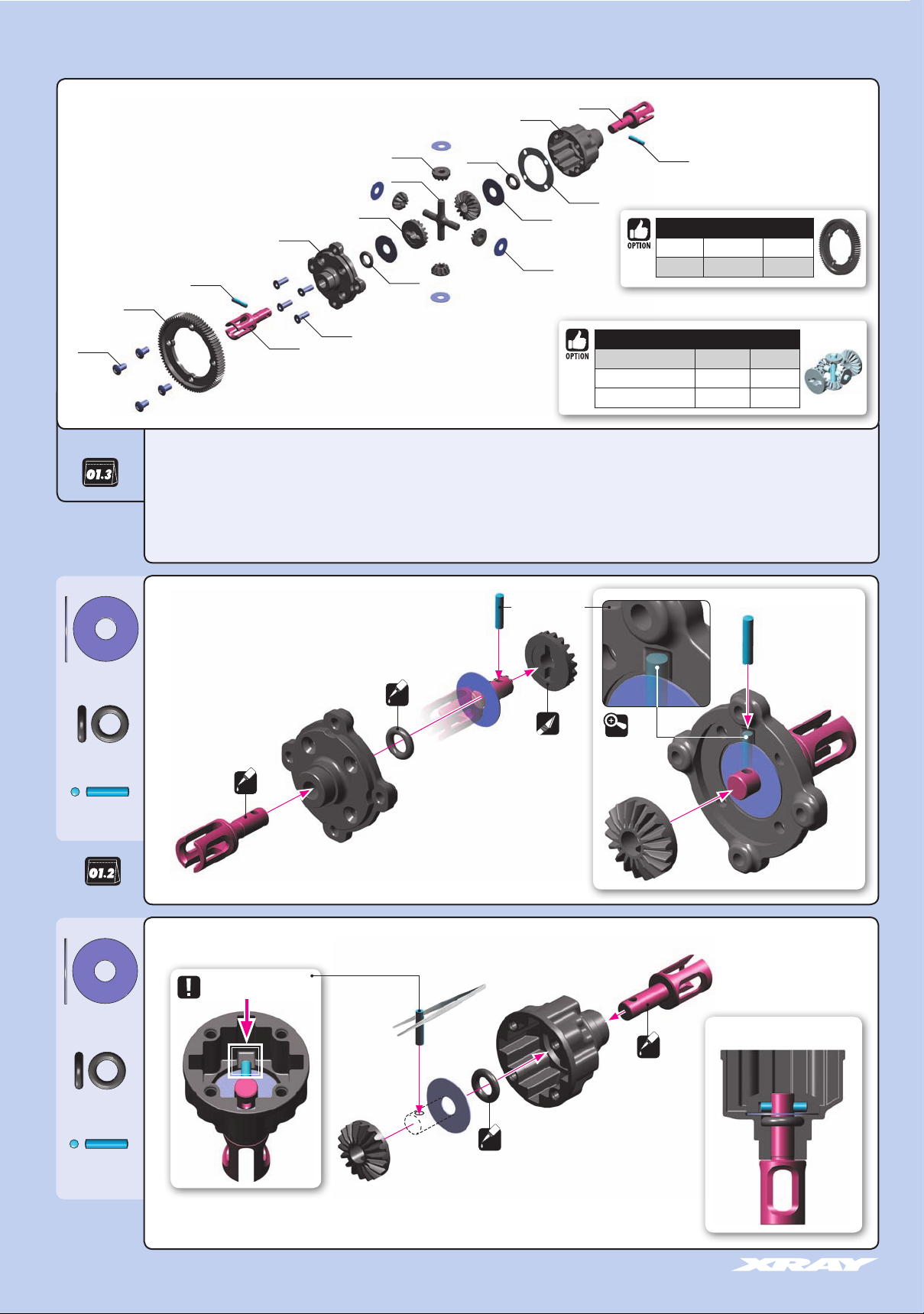
1. GEAR CENTER DIFFERENTIAL
902306
BAG
304930
364911
981210
364981
364970
903258
304930 COMPOSITE GEAR DIFF BEVEL & SATELLITE GEARS (2+4)
304980 COMPOSITE GEAR DIFF CROSS PIN
304990 DIFF GASKET (4)
364901 GEAR CENTER DIFFERENTIAL - SET
364910 COMPOSITE GEAR DIFFERENTIAL CASE
364911 COMPOSITE CENTER GEAR DIFFERENTIAL ADAPTER
364970 CENTER DIFF OUTDRIVE ADAPTER - HUDY SPRING STEEL™ (2)
364981 COMPOSITE CENTER DIFF SPUR GEAR 81T / 48
304930
304980
972050
364910
364970
972050
304990
964050
964031
902306 HEX SCREW SH M3x6 (10)
903258 HEX SCREW SFH M2.5x8 (10)
964031 WASHER S 3.5x10x0.2 (10)
964050 WASHER S 5x15x0.3 (10)
972050 SILICONE O-RING 5x2 (10)
981210 PIN 2x10 (10)
981210
CENTER DIFF SPUR GEARS
#364978 78T/48 OPTION
#364981 81T/48 INCLUDED
BEVEL & SATELITTE GEARS + PINS
#304930 + #304980 COMPOSITE INCLUDED
#335030 + #335080 STEEL OPTION
#304931 + #304980
GRAPHITE
OPTION
964050
S 5x15x0.3
972050
O 5x2
981210
P 2x10
964050
S 5x15x0.3
OIL
➊
NOTE ORIENTATION
➍
STEP DETAIL
Use tweezers to
insert pin
OIL
STEP DETAIL
➍
➋
➍
➋
➌
➍➎
➍
➌
DETAIL
➎
➊
CUTAWAY VIEW
OIL
972050
O 5x2
981210
P 2x10
➎
OIL
8
Page 9
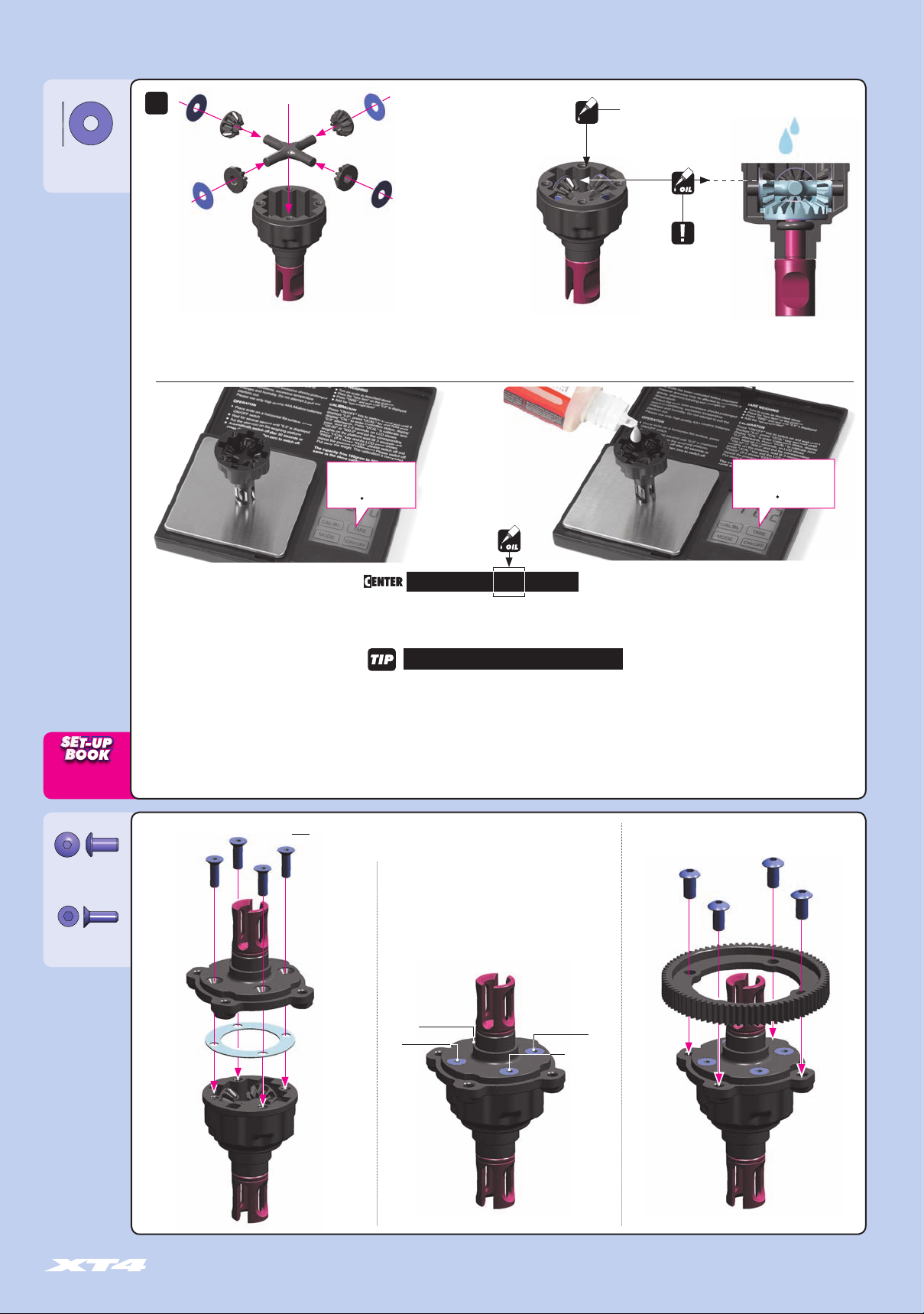
1. GEAR CENTER DIFFERENTIAL
964031
S 3.5x10x0.2
2x
Center diff
OIL
Silicone oil 100.000cSt
Fill just above the cross-pins.
PROPER AMOUNT OF OIL IN THE DIFFS
Use a digital scale to measure the exact amount
of oil in the diff. Remember that during operation
the diff gets hotter and the heat may allow the oil
to expand. If there is too much oil inside it may
interfere with the diff operation and damage the
internal gears.
Fill differential up to the top of the
diff cross-pins. DO NOT fill the diff
to the top of the housing.
TO ENSURE YOU HAVE THE SAME AMOUNT OF OIL FROM REBUILD TO REBUILD, DO THE FOLLOWING:
#107865
HUDY Ultimate Digital Pocket
Scale 300g±0.01g
1 1.00
g
100.000cSt
1250
g
DIFFERENTIAL OIL
902306
SH M3x6
903258
SFH M2.5x8
➊ Put the diff (without oil) on the scale and
check the weight (approximately 9.80g)
2.5x8mm
Tighten the screws equally but do NOT
tighten them completely.
11.00g + 1.50g = 12.50gDiff.
FOR CENTER DIFFERENTIAL
LOW TRACTION 50.000cSt (HUDY #106550)
MEDIUM TRACTION 100.000cSt (HUDY #106610)
HIGH TRACTION 500.000cSt (HUDY #106650)
NOTE:
Softer oil increases steering, harder oil increases stability.
Finish tightening in this order.
➋ Slowly pour oil into the diff and watch the weight.
3x6mm
➊
➌
➍
➋
9
Page 10
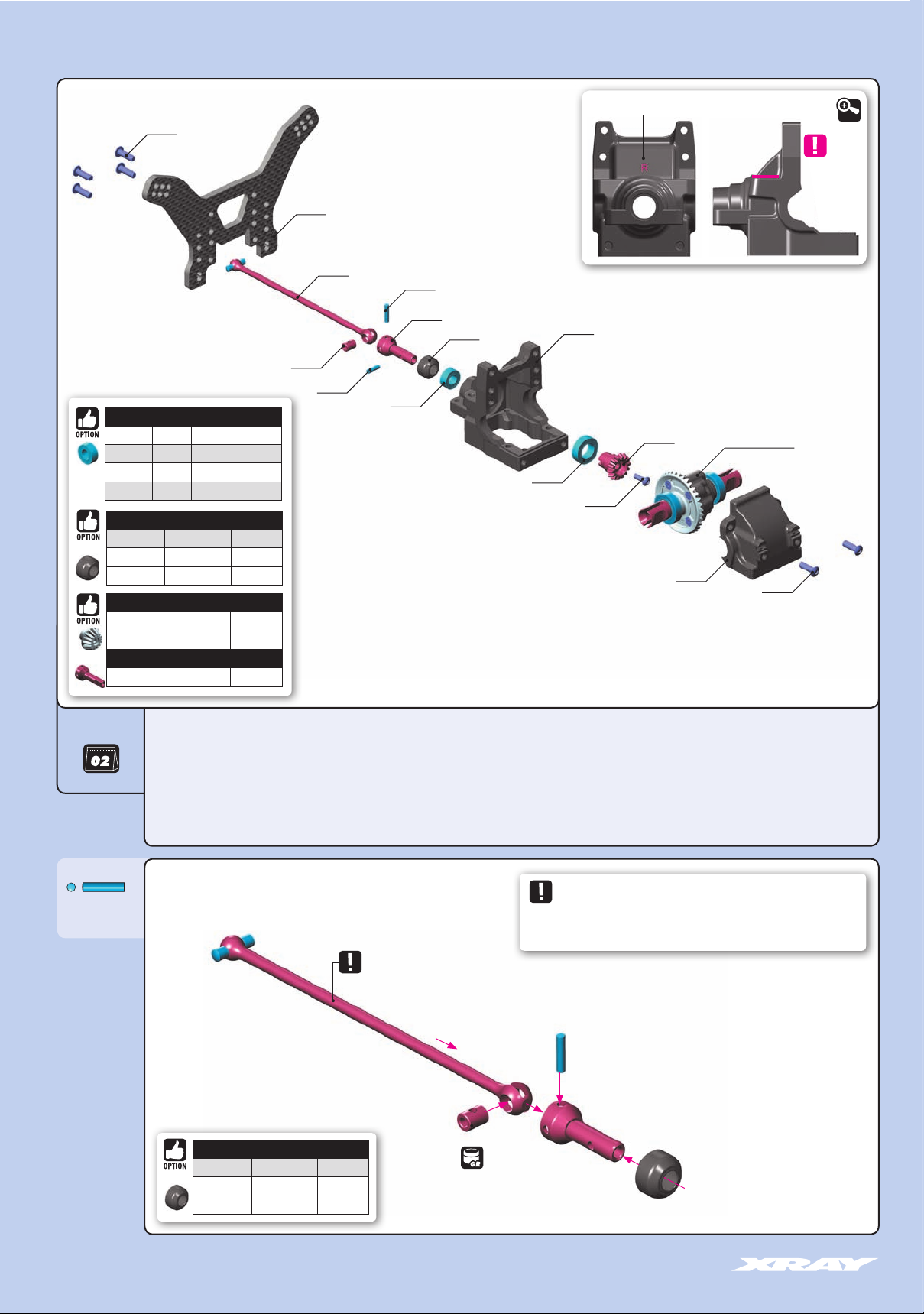
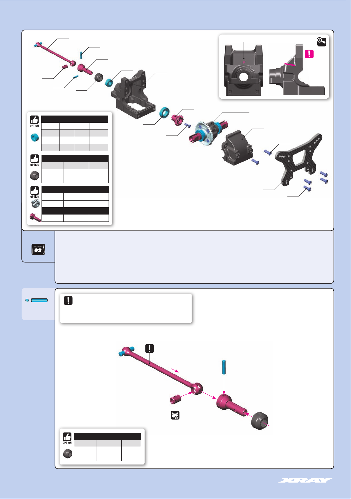
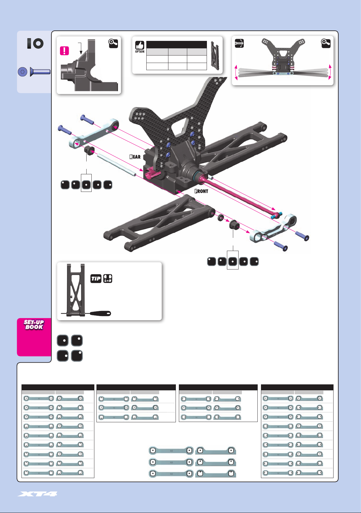
2. REAR CENTRAL TRANSMISSION
902310
XRAY BALL-BEARINGS
#359050 5x10x4 GREASE OPTION
#940510 5x10x4 OIL INCLUDED
#940814 8x14x4 GREASE OPTION
#940815 8x14x4 OIL INCLUDED
DRIVE SHAFT COLLARS
#365470 COMPOSITE INCLUDED
#365471-K ALU - BLACK OPTION
#365471-O ALU - ORANGE OPTION
BEVEL DRIVE GEARS
#365114 GRAPHITE OPTION
#365134 STEEL OPTION
+
CENTRAL SHAFT UNIVERSAL JOINTS
#365440 OPTION
363083
365230
365427
981208
940510
980210
365442
365470
940815
362003
902306
MARKED “R“
365124
362003
364902+364955
902310
DETAIL
IMPORTANT
REAR BLOCK
BAG
980210
P 2x10
362003 DIFF BULKHEAD BLOCK SET REAR
363083 XT4 GRAPHITE SHOCK TOWER REAR 3.5MM
365124 STEEL BEVEL DRIVE GEAR 14T
365230 DRIVE SHAFT COUPLING - HUDY SPRING STEEL™
365427 CENTRAL DRIVE SHAFT 105MM - HUDY SPRING STEEL™
365442 CENTRAL SHAFT UNIVERSAL JOINT
365470 COMPOSITE DRIVE SHAFT SAFETY COLLAR - V2 (3)
902306 HEX SCREW SH M3x6 (10)
CENTRAL DRIVE SHAFT (105mm)
DRIVE SHAFT COLLARS
#365470 COMPOSITE INCLUDED
#365471-K ALU - BLACK OPTION
#365471-O ALU - ORANGE OPTION
902310 HEX SCREW SH M3x10 (10)
940510 BALL-BEARING 5x10x4 RUBBER SEALED - OIL (2)
940815 BALL-BEARING 8x14x4 RUBBER SEALED - OIL (2)
980210 PIN 2x10 (10)
981208 PIN 2x8 (10)
364902 GEAR DIFFERENTIAL FOR 2.5MM PIN - SET
364955 STEEL DIFFERENTIAL BEVEL GEAR 35T
DRIVE SHAFT COVER CAPS
Lubricate the drive shaft connecting joint properly so the drive shaft turns
freely. In the event that not enough grease is used, the connecting pin may lock
and may even, in extreme situations, push through the drive shaft cover cap.
➋
➌
➊
➍
#106210 HUDY GRAPHITE GREASE
#106213 HUDY JOINT GREASE - OPTION
10
Page 11
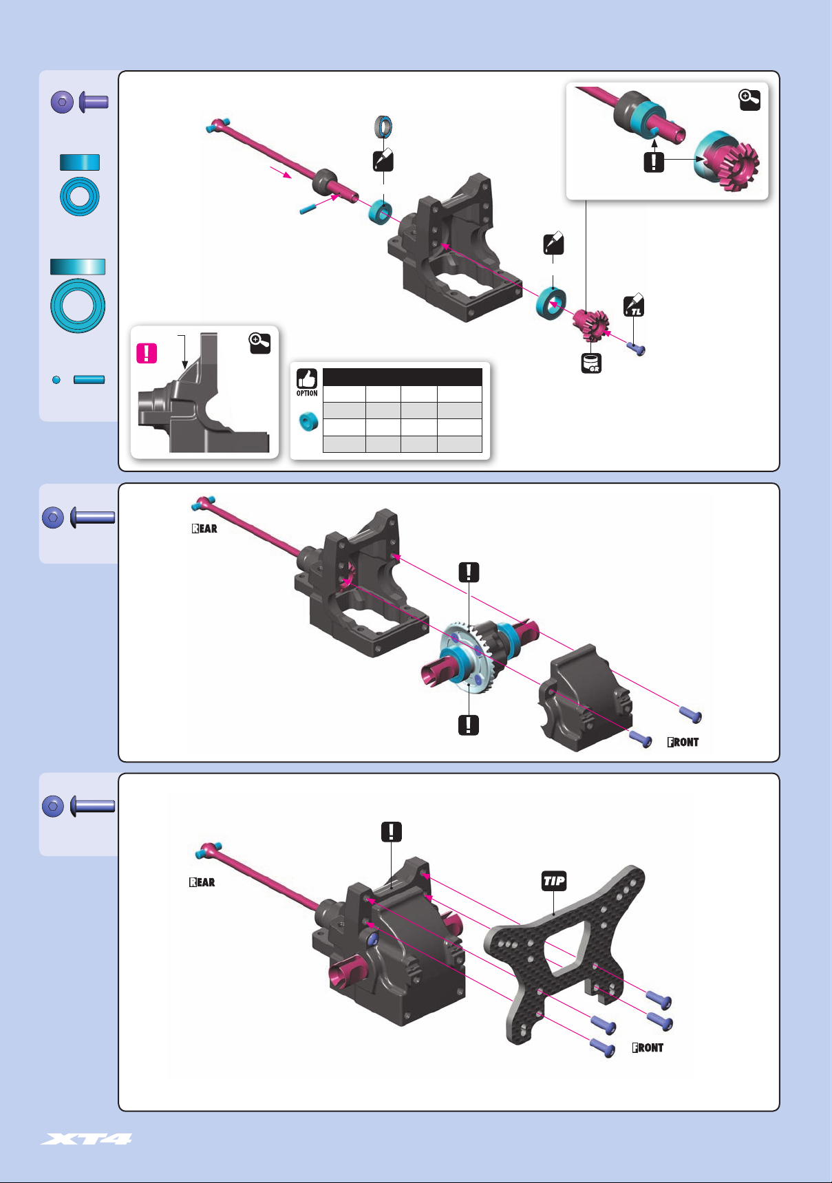
2. REAR CENTRAL TRANSMISSION
902306
SH M3x6
940510
BB 5x10x4
940815
BB 8x14x4
981208
P 2x8
902310
SH M3x10
Marked “R”
REAR BLOCK
XRAY BALL-BEARINGS
#359050 5x10x4 GREASE OPTION
#940510 5x10x4 OIL INCLUDED
#940814 8x14x4 GREASE OPTION
#940815 8x14x4 OIL INCLUDED
DETAIL
Bearing with BLUE
DETAIL
rubber covers
➌
OIL
5x10x4mm
Bearing Oil
(HUDY #106230)
NOTE ORIENTATION
Bearing Oil
➍
➊
(HUDY #106230)
OIL
8x14x4mm
GRAPHITE GREASE
(HUDY #106210)
➋
➎
➏
THREAD LOCK
NOTE ORIENTATION
902310
SH M3x10
REAR DIFF 10.000cSt
ALTERNATIVE 2
SHOCKS MOUNTED BEHIND REAR SHOCK TOWER
DO NOT USE FOR BASIC SET-UP
Follow the TECH TIP on page 5
to prepare graphite parts
ALTERNATIVE 1
SHOCKS MOUNTED IN FRONT OF REAR SHOCK TOWER
(INITIAL SETTING)
NOTE
Alternatives shock mounted folow page 39 / step 2 and 3.
11
Page 12
2. FRONT CENTRAL TRANSMISSION
365426
365230
981208
365470
XRAY BALL-BEARINGS
#359050 5x10x4 GREASE OPTION
#940510 5x10x4 OIL INCLUDED
#940814 8x14x4 GREASE OPTION
#940815 8x14x4 OIL INCLUDED
DRIVE SHAFT COLLARS
#365470 COMPOSITE INCLUDED
#365471-K ALU - BLACK OPTION
#365471-O ALU - ORANGE OPTION
BEVEL DRIVE GEARS
#365114 GRAPHITE OPTION
#365134 STEEL OPTION
+
CENTRAL SHAFT UNIVERSAL JOINTS
#365440 OPTION
980210
365442
940510
940815
362002
902306
365124
MARKED “F“
364902+ 364955
362002
362084
902310
902310
DETAIL
IMPORTANT
FRONT BLOCK
BAG
980210
P 2x10
362002 DIFF BULKHEAD BLOCK SET FRONT
362084 XT4 GRAPHITE SHOCK TOWER FRONT 3.5MM
365124 STEEL BEVEL DRIVE GEAR 14T
365230 DRIVE SHAFT COUPLING - HUDY SPRING STEEL™
365426 CENTRAL DRIVE SHAFT 72MM - HUDY SPRING STEEL™
365442 CENTRAL SHAFT UNIVERSAL JOINT
365470 COMPOSITE DRIVE SHAFT SAFETY COLLAR - V2 (3)
902306 HEX SCREW SH M3x6 (10)
DRIVE SHAFT COVER CAPS
Lubricate the drive shaft connecting joint properly so the drive shaft turns
freely. In the event that not enough grease is used, the connecting pin may lock
and may even, in extreme situations, push through the drive shaft cover cap.
CENTRAL DRIVE SHAFT (72mm)
902310 HEX SCREW SH M3x10 (10)
940510 BALL-BEARING 5x10x4 RUBBER SEALED - OIL (2)
940815 BALL-BEARING 8x14x4 RUBBER SEALED - OIL (2)
980210 PIN 2x10 (10)
981208 PIN 2x8 (10)
364902 GEAR DIFFERENTIAL FOR 2.5MM PIN - SET
364955 STEEL DIFFERENTIAL BEVEL GEAR 35T
➋
➌
12
➊
➍
#106210 HUDY GRAPHITE GREASE
#106213 HUDY JOINT GREASE - OPTION
DRIVE SHAFT COLLARS
#365470 COMPOSITE INCLUDED
#365471-K ALU - BLACK OPTION
#365471-O ALU - ORANGE OPTION
Page 13
902306
SH M3x6
940510
BB 5x10x4
2. FRONT CENTRAL TRANSMISSION
Bearing with BLUE
rubber covers
➍
OIL
5x10x4mm
➊
Bearing Oil
(HUDY #106230)
NOTE ORIENTATION
Bearing Oil
(HUDY #106230)
OIL
8x14x4mm
DETAIL
940815
BB 8x14x4
981208
P 2x8
902310
SH M3x10
Marked “F”
DETAIL
XRAY BALL-BEARINGS
#359050 5x10x4 GREASE OPTION
#940510 5x10x4 OIL INCLUDED
#940814 8x14x4 GREASE OPTION
#940815 8x14x4 OIL INCLUDED
➋
GRAPHITE GREASE
(HUDY #106210)
NOTE ORIENTATION
THREAD LOCK
➌
➎
902310
SH M3x10
FRONT DIFF 30.000cSt
NOTE ORIENTATION
Follow the TECH TIP on page 5
to prepare graphite parts
13
Page 14
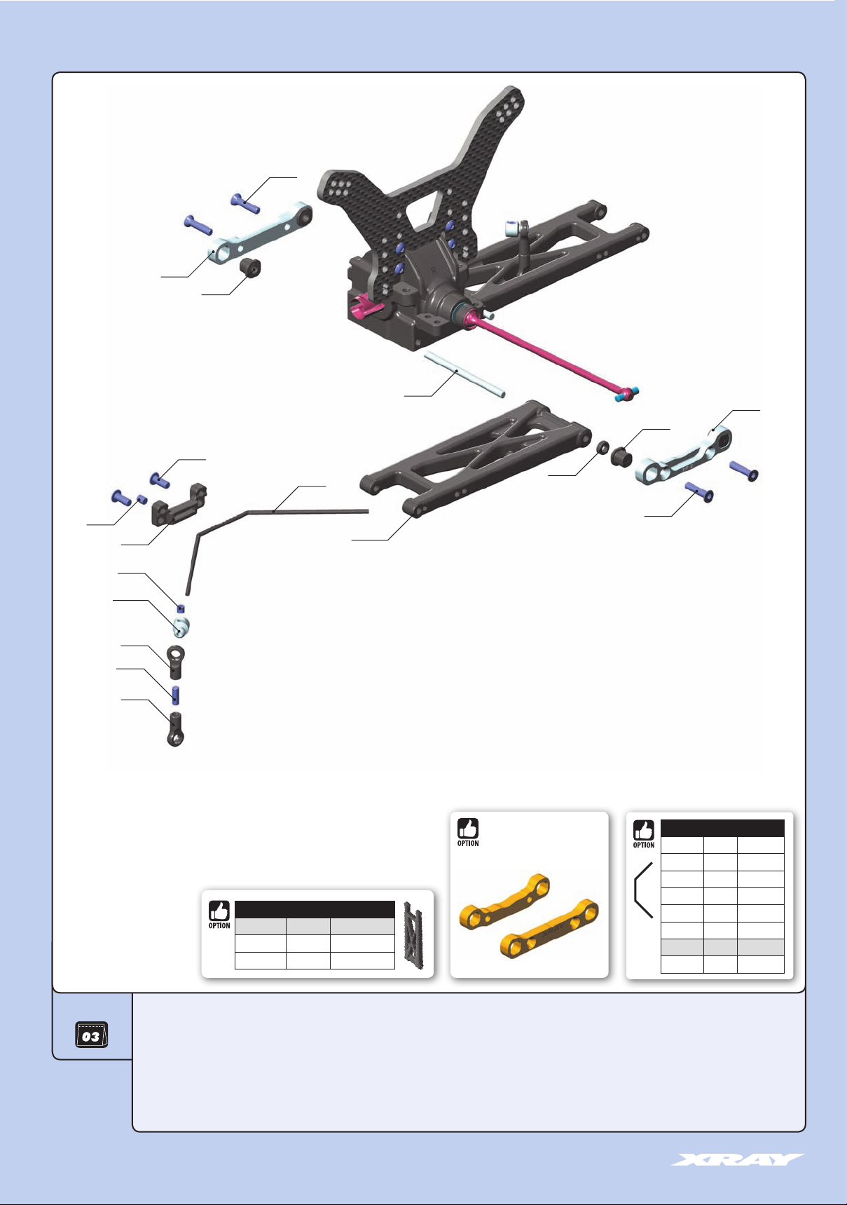
3. REAR SUSPENSION
903312
363321
362315
902308
362478
367210
363311
362315
306219
901304
362003
901303
303431-K
303454
901308
303454
323112-M
REAR SUSPENSION ARMS
#323112-M MEDIUM INCLUDED
#323112-H HARD OPTION
#323112-G GRAPHITE OPTION
#363313
BRASS REAR LOWER SUSPENSION
HOLDER SET +2 - RR+RF
903312
ANTI-ROLL BARS
#362470 1.0mm
#362471 1.1mm
#362472 1.2mm
#362473 1.3mm
#362474 1.4mm
#362476 1.6mm
#362478 1.8mm
#362480 2.0mm
OPTION
OPTION
OPTION
OPTION
OPTION
OPTION
INCLUDED
OPTION
14
BAG
303431-K ALU 4.9MM BALL END - BLACK (2)
303454 BALL JOINT 4.9MM - OPEN (4)
306219 COMPOSITE SET OF SERVO SHIMS (4)
362003 DIFF BULKHEAD BLOCK SET REAR
362315 ECCENTRIC BUSHING SET (2)
362478 ANTI-ROLL BAR 1.8 MM
323112-M XT4 COMPOSITE SUSPENSION ARM REAR LOWER - MEDIUM
363311 ALU REAR LOWER SUSP. HOLDER +2 - FRONT - 7075 T6 (5MM)
363321 ALU REAR LOWER SUSP. HOLDER +2 - REAR - 7075 T6 (5MM)
367210 SUSPENSION PIVOT PIN (2)
901303 HEX SCREW SB M3x3 (10)
901304 HEX SCREW SB M3x4 (10)
901308 HEX SCREW SB M3x8 (10)
902308 HEX SCREW SH M3x8 (10)
903312 HEX SCREW SFH M3x12 (10))
Page 15
3. REAR SUSPENSION
306219
SHIM 3x6x2
903312
SFH M3x12
Marked “R”
➍
➊
INITIAL POSITION
1º 1º0.5º 0.5º0º
Composite eccentric bushings
DETAIL
REAR SUSPENSION ARMS
DETAIL
#323112-M MEDIUM INCLUDED
#323112-H HARD OPTION
#323112-G GRAPHITE OPTION
Check for free movement
➌
RR
➋
3x6x2mm
➌
RF
➊
INITIAL POSITION
➍
1º 1º0.5º 0.5º0º
Composite eccentric bushings
All possible mounting
If the suspension arm does not move freely use a
alternatives of eccentric bushings
HUDY Arm Reamer to size the holes of the arms
Arm Reamer 3.0mm
(HUDY #107633)
ECCENTRIC BUSHINGS HAVE TWO DIFFERENT OFFSETS FROM THE CENTER.
TOE-IN
ANTI-SQUAT
ROLL CENTER
Middle position = 0.5° or 0.375mm from center.
TRACK-WIDTH
Outer position = 1° or 0.75mm from center.
The XRAY rear alu lower suspension holders provide great range of adjustment for the rear suspension. Using different combinations of eccentric bushings, fine adjustment of rear anti-squat, rear toe-in, rear
roll center, and rear track-width can be obtained. For more information about the influence of rear anti-squat, rear toe-in, rear roll center and rear track width on car handling, please refer to HUDY Set-up Book
(#209100).
ANTI-SQUAT ROLL CENTER TRACK-WIDTH TOE-IN
RR RR RR RRRF RF
=2°
=3°
=1°
=3°
=2°
=4°
=1°
=2°
=0°
=+0.75mm
=
0mm
=-0.75mm
The tables describe the amounts of adjustment using the center and outside positions of the
eccentric bushings. The middle position eccentric bushings allow for finer adjustment increments.
Example:
0(RR) - 0 (RF) = 2°
0(RR) - 0.5 (RF) = 2.5°
0(RR) - 1 (RF) = 3°
RF
=+1.5mm
=
0mm
=-1.5mm
RF(°) (mm) (mm) (°)
=3°
=4°
=2°
=2°
=3°
=1°
= 2°
= 2.5°
= 3°
=4°
=5°
=3°
15
Page 16

3. REAR SUSPENSION
2x
L=R
901308
SB M3x8
DETAIL
1.5mm
4mm
901303
SB M3x3
901304
SB M3x4
902308
SH M3x8
ANTI-ROLL BARS
#362470 1.0mm
#362471 1.1mm
#362472 1.2mm
#362473 1.3mm
#362474 1.4mm
#362476 1.6mm
#362478 1.8mm
#362480 2.0mm
OPTION
OPTION
OPTION
OPTION
OPTION
OPTION
INCLUDED
OPTION
➋
3x3mm
➌
STEP DETAIL
L=R
DETAIL
0mm
➌
16
ANTI-ROLL BAR
Step check for free movement
➊
1.8mm
➊
Step
➊
Loosen the 3x4 setscrew if
the anti-roll bar does not
turn freely
3x4mm
3x8mm
DETAILDETAIL
Page 17

903312
3. FRONT SUSPENSION
362320
901303
303431-K
362315
901308
303454
322112-M
303454
367210
306219
306219
362478
303121-K
362002
306219
902308
901304
362315
903312
361200
362310
902308
ANTI-ROLL BARS
#362470 1.0mm
#362471 1.1mm
#362472 1.2mm
#362473 1.3mm
#362474 1.4mm
#362476 1.6mm
#362478 1.8mm
#362480 2.0mm
BAG
OPTION
OPTION
OPTION
OPTION
OPTION
OPTION
INCLUDED
OPTION
303121-K ALU SHIM 3x6x0.5MM - BLACK (10)
303431-K ALU 4.9MM BALL END - BLACK (2)
303454 BALL JOINT 4.9MM - OPEN (4)
306219 COMPOSITE SET OF SERVO SHIMS (4)
322112-M XT4 COMPOSITE SUSPENSION ARM FRONT LOWER - MEDIUM
361200 COMPOSITE BUMPER - V2
362002 DIFF BULKHEAD BLOCK SET FRONT - V2
362310 ALU FRONT LOWER SUSP. HOLDER - FRONT - 7075 T6 (5MM)
362315 ECCENTRIC BUSHING SET (2)
SUSPENSION ARMS
#322112-M MEDIUM INCLUDED
#322112-G GRAPHITE OPTION
362320 ALU FRONT LOWER SUSP. HOLDER - REAR - 7075 T6 (5MM)
362478 ANTI-ROLL BAR 1.8 MM
367210 SUSPENSION PIVOT PIN (2)
901303 HEX SCREW SB M3x3 (10)
901304 HEX SCREW SB M3x4 (10)
901308 HEX SCREW SB M3x8 (10)
902308 HEX SCREW SH M3x8 (10)
903312 HEX SCREW SFH M3x12 (10))
17
Page 18

3. FRONT SUSPENSION
303121-K
SHIM 3x6x0.5
306219
SHIM 3x6x1
306219
SHIM 3x6x2
903312
SFH M3x12
Marked “F”
➍
➊
INITIAL POSITION
1º 0.5º 0.5º0º
Composite eccentric bushings
DETAIL
SUSPENSION ARMS
DETAIL
#322112-M MEDIUM INCLUDED
#322112-G GRAPHITE OPTION
Check for free movement
➌
FR
➋
1º
3x6x0.5mm
NOTE ORIENTATION
3x6x1mm
3x6x2mm (2x)
FF
➌
➊
➍
INITIAL POSITION
NOTE ORIENTATION
1º 1º0.5º 0.5º0º
Composite eccentric bushings
If the suspension arm does not move freely use a
HUDY Arm Reamer to size the holes of the arms
Arm Reamer 3.0mm
(HUDY #107633)
ECCENTRIC BUSHINGS HAVE TWO DIFFERENT OFFSETS FROM THE CENTER.
KICK UP
ROLL CENTER
Middle position = 0.5° or 0.375mm from center.
TRACK-WIDTH
Outer position = 1° or 0.75mm from center.
The XRAY alu front lower suspension holders provide great range of adjustment for the front suspension. Using different combinations of eccentric bushings, fine adjustment of front kick-up, roll-center, and front
track-width can be obtained. For more information about the influence of kick-up, front track-width, and roll centers on car handling, please refer to HUDY Set-up Book (#209100).
KICK-UP
FF
FR
(°)
=9°
=8°
=10°
=8°
=7°
The tables describe the amounts of adjustment using the center and outside positions of the eccentric bushings.
=9°
The middle position eccentric bushings allow for finer adjustment increments.
=10°
Example:
=9°
0(FF) - 0(FR) = 9°
=11°
0.5(FF) - 0(FR) = 9.5°
(mm) (mm)
=+0.75mm
=
0mm
=-0.75mm
The track-width is directly influenced by the size of the
wheels and tires used.
TRACK-WIDTHROLL CENTER
FFFF
FRFR
=+1.5mm
=
0mm
=-1.5mm
= 9°
= 9.5°
TOTAL CASTER=C-HUB CASTER+KICK UP
KICK-UP
C-HUB CASTER
7° 8° 9° 10° 11°
6° 13° 14° 15° 16° 17°
9° 16° 17° 18° 19° 20°
Caster is the angle between the steering pivot
axis and the vertical plane. Caster is affected not
only by the C-Hub caster, but also by the front
kick-up angle relative to the flat chassis bottom.
The table indicates how kick up angle effects
total caster.
The XT4’s stock caster blocks are 9°, but 6°
blocks are available as an option.
18
1(FF) - 0(FR) = 10°
= 10°
Page 19

901308
SB M3x8
902308
SH M3x8
2x
3. FRONT SUSPENSION
L=R
DETAIL
1.5mm
4mm
901303
SB M3x3
901304
SB M3x4
902308
SH M3x8
3x3mm
STEP DETAIL
➌
L=R
➌
➋
0mm
DETAIL
➊
ANTI-ROLL BARS
#362470 1.0mm
#362471 1.1mm
#362472 1.2mm
#362473 1.3mm
#362474 1.4mm
#362476 1.6mm
#362478 1.8mm
#362480 2.0mm
OPTION
OPTION
OPTION
OPTION
OPTION
OPTION
INCLUDED
OPTION
3x4mm
3x8mm
ANTI-ROLL BAR
DETAIL
Step check for free movement
➊
Step
➊
Loosen the 3x4 setscrew if
the anti-roll bar does not
turn freely
DETAIL
19
Page 20

4. REAR TRANSMISSION
322612
302665
362651
363520
302665
362651
362280
962030
962031
902312
#325341
REAR ADJUSTABLE DRIVE AXLE
LB - HUDY SPRING STEEL™ +
325390 ALU SHIM 10x12x2MM (2)
902205
362316
323354-H
365360
323382
940513
960030
980210
941014
306219
908210
325340
327321
902310
325316
365230
902254
961025
#323381
ALU REAR HUB PLATE FOR MULTI ADJ.
UPRIGHT - 2-HOLE - SWISS 7075 T6
XRAY BALL-BEARINGS
#940512 5x12x4 OIL OPTION
#941015 10x15x4 OIL OPTION
#940513 5x12x4 GREASE INCLUDED
#941014 10x15x4 GREASE INCLUDED
REAR UPRIGHTS
#323354-H COMPOSITE - H INCLUDED
#323354-G COMPOSITE - G OPTION
#323355 ALU OPTION
BAG
30 2665 COMPOSITE BALL JOINT 4.9MM - CLOSED WITH HOLE (4)
30 6219 CCOMPOSITE SET OF SERVO SHIMS (4)
32 2612 ADJ. TURNBUCKLE 75MM M3 L/R - HUDY SPRING STEEL™ (2)
32 3354-H COMPOSITE UPRIGHT REAR - HARD
32 3382 ALU REAR HUB PLATE FOR MULTI ADJ. UPRIGHT - 1-HOLE
32 5316 XT4 REAR DRIVE SHAFT 92MM WITH 2.5MM PIN - SPRING STEEL™
32 5340 REAR DRIVE AXLE LB - HUDY SPRING STEEL™
32 7321 REAR ARM PIVOT PIN 3x34MM(2)
36 2280 ALU CONICAL SHIM 3x6x2.0MM (10)
36 2316 OPEN ECCENTRIC BUSHING SET (2)
36 2651 BALL END 4.9MM WITH THREAD 8MM (2)
36 3520 REAR WING POST - V2 (2)
36 5230 DRIVE SHAFT COUPLING - HUDY SPRING STEEL™
36 5360 ALU WHEEL HUB 12MM - OFFSET “+4.5MM” (2)
ALU CONICAL SHIMS
#362280 SILVER INCLUDED
#362280-K BLACK OPTION
#362280-O ORANGE OPTION
ALU NUTS M3
#296530-B ALU BLUE OPTION
#296530-K ALU BLACK OPTION
#296530-O ALU ORANGE OPTION
#960030 STEEL SILVER INCLUDED
#960031 ALU SILVER OPTION
90 2205 HEX SCREW SH M2x5 (10)
90 2254 HEX SCREW SH M2.5x4 (10)
90 2310 HEX SCREW SH M3x10 (10)
90 2312 HEX SCREW SH M3x12 (10)
94 0513 BALL-BEARING 5x12x4 RUBBER SEALED - GREASE (2)
94 1014 BALL-BEARING 10x15x4 RUBBER SEALED - GREASE (2)
96 0030 NUT M3 (10)
96 1025 WASHER S 2.5 (10)
96 2030 WASHER S 3x6x0.3 (10)
96 2031 WASHER S 3x6x0.1 (10)
98 0210 PIN 2x10 (10)
WHEEL HUBS 12MM
#365360 +4.5mm - 6 slots INCLUDED
#365359 +3.75mm - 5 slots OPTION
#365358 +3.0mm - 4 slots OPTION
#365357 +2.25mm - 3 slots OPTION
#365356 +1.5mm - 2 slots OPTION
#365355 +0.75mm - 1 slot OPTION
#365353 0mm - 0 slots OPTION
#365354 -0.75mm - Lightw. OPTION
WHEEL HUBS 14MM
#365352 +0.75mm OPTION
#365350 0mm OPTION
#365351 -0.75mm OPTION
20
Page 21

980210
P 2x10
2x
L=R
4. REAR TRANSMISSION
DRIVE SHAFT (92mm)
➌
#325341
➊
REAR ADJUSTABLE DRIVE AXLE LB - HUDY SPRING
STEEL™ + 325390 ALU SHIM 10x12x2MM (2)
940513
BB 5x12x4
941014
BB 10x15x4
980210
P 2x10
902205
SH M2x5
➋
LONG AXLE
2x
L=R
Use HUDY Ball-Bearing Grease
#106220 - STANDARD
#106221 - BLUE
#106222 - RED
➋
➏
➎
5x12x4mm
Bearing with BLACK
rubber covers
XRAY BALL-BEARINGS
#940512 5x12x4 OIL OPTION
#941015 10x15x4 OIL OPTION
#940513 5x12x4 GREASE INCLUDED
#941014 10x15x4 GREASE INCLUDED
➊
10x15x4mm
#106210 HUDY GRAPHITE GREASE
#106213 HUDY JOINT GREASE - OPTION
➌
➍
WHEEL HUBS 12MM
#365360 +4.5mm - 6 slots INCLUDED
#365359 +3.75mm - 5 slots OPTION
#365358 +3.0mm - 4 slots OPTION
#365357 +2.25mm - 3 slots OPTION
#365356 +1.5mm - 2 slots OPTION
#365355 +0.75mm - 1 slot OPTION
#365353 0mm - 0 slots OPTION
#365354 -0.75mm - Lightw. OPTION
OPTIONAL HEX HUB EFFECTS
Different offset hex hubs are used to increase or
decrease the track-width.
LESS OFFSET
Rear - more traction
Front - more steering
MORE OFFSET
Rear - less traction
Front - less steering
REAR UPRIGHTS
#323354-H HARD INCLUDED
#323354-G GRAPHITE OPTION
#323355 ALU OPTION
902312
SH M3x12
2x
L=R
ALTERNATIVE ORIENTATION
NOTE ORIENTATION
INITIAL SETTING
#323381
ALU REAR HUB PLATE FOR MULTI ADJ.
UPRIGHT - 2-HOLE - SWISS 7075 T6
21
Page 22

4. REAR TRANSMISSION
306219
SHIM 3x6x2
902254
SH M2.5x4
961025
962030
S 3x6x0.3
WHEELBASE
S 2.5
962031
S 3x6x0.1
Use 0.1mm or 0.3mm shim
to adjust the play.
3x6x0.1mm
3x6x0.3mm
2x
L=R
3x6x2mm
S 2.5
TIGHTEN
GENTLY
NOTE ORIENTATION
S 2.5
8mm THREAD
TIGHTEN
GENTLY
DETAIL
Check for free
movement
LONGER WHEELBASE (INITIAL SETTING)
Adjustment Shim IN FRONT OF HUB
moves hub rearward.
ARM
SHORTER WHEELBASE
Adjustment Shim BEHIND HUB moves
hub forward.
ARM
CAMBER
362280
CON. SHIM 3x6x2
960030
N M3
ROLL CENTER
2x
8mm THREAD
L=R
CONICAL SHIM
3x6x2mm
THREAD
NOTE
ORIENTATION
THREAD
Install the pivot balls with Professional
Multi Tool (HUDY #183011)
ALU CONICAL SHIMS
#362280 SILVER INCLUDED
#362280-K BLACK OPTION
#362280-O ORANGE OPTION
NOTE
ORIENTATION
DETAIL
DETAIL
59mm
2x
L=R
INITIAL SETTING
INITIAL SETTING
L=R
L=R
22
902310
SH M3x10
2x
L=R
Page 23

4. FRONT TRANSMISSION
WHEEL HUBS 12MM
#365360 +4.5mm OPTION
#365359 +3.75mm OPTION
#365358 +3.00mm OPTION
#365357 +2.25mm OPTION
#365356 +1.5mm OPTION
#365355 +0.75mm OPTION
#365353 0mm INCLUDED
#365354 -0.75mm OPTION
WHEEL HUBS 14MM
#365352 +0.75mm OPTION
#365350 0mm OPTION
#365351 -0.75mm OPTION
940513
365353
359050
C-HUBS
#362210 RIGHT 9° - M OPTION
#362210-H RIGHT 9° - H INCLUDED
#362210-G RIGHT 9° - G OPTION
#362211 RIGHT 6° OPTION
#362234 ALU RIGHT 12° OPTION
#362220 LEFT 9° - M OPTION
#362220-H LEFT 9° - H INCLUDED
#362220-G LEFT 9° - G OPTION
#362221 LEFT 6° OPTION
#362244 ALU LEFT 12° OPTION
980210
980210
365240
365470
362291
902314
362210-H
365230
902312
362652
362280
325317
302665
302665
362651
322611
960030
ALU NUTS M3
#296530-B ALU BLUE OPTION
#296530-K ALU BLACK OPTION
#296530-O ALU ORANGE OPTION
#960030 STEEL SILVER INCLUDED
#960031 ALU SILVER OPTION
ALU CONICAL SHIMS
#362280 SILVER INCLUDED
#362280-K BLACK OPTION
#362280-O ORANGE OPTION
STEERING BLOCKS
#362250 MEDIUM OPTION
#362250-H HARD INCLUDED
#362250-G GRAPHITE OPTION
BAG
362290
362250-H
902205
327220
961025
302665 COMPOSITE BALL JOINT 4.9MM - CLOSED WITH HOLE (4)
322611 ADJ. TURNBUCKLE M3 L/R 70 MM - SPRING STEEL (2)
325317 XT4 FRONT DRIVE SHAFT 99MM WITH 2.5MM PIN - HUDY SPRING STEEL™
327220 FRONT ARM PIVOT PIN (2)
362210-H COMPOSITE C-HUB 9° DEG. RIGHT - HARD
362220-H COMPOSITE C-HUB 9° DEG. LEFT - HARD
362250-H COMPOSITE STEERING BLOCK - HARD
362280 ALU CONICAL SHIM 3x6x2.0MM (10)
362290 STEEL STEERING BUSHING - SHORT (2)
362291 STEEL STEERING BUSHING - LONG (2)
362651 BALL END 4.9MM WITH THREAD 8MM (2)
362652 BALL END 4.9MM WITH THREAD 10MM (2)
365230 DRIVE SHAFT COUPLING - HUDY SPRING STEEL™
902254
362220-H
XRAY BALL-BEARINGS
#940510 5x10x4 OIL OPTION
#940512 5x12x4 OIL OPTION
#359050 5x10x4 GREASE INCLUDED
#940513 5x12x4 GREASE INCLUDED
DRIVE SHAFT COLLARS
#365470 COMPOSITE INCLUDED
#365471-K ALU - BLACK OPTION
#365471-O ALU - ORANGE OPTION
365240 FRONT DRIVE AXLE - HUDY SPRING STEEL™
365353 ALU WHEEL HUB 12MM (2)
365470 COMPOSITE DRIVE SHAFT SAFETY COLLAR (3)
359050 BALL-BEARING 5x10x4 STEEL SEALED - GREASE (2)
902205 HEX SCREW SH M2x5 (10)
902254 HEX SCREW SH M2.5x4 (10)
902312 HEX SCREW SH M3x12 (10)
902314 HEX SCREW SH M3x14 (10)
940513 BALL-BEARING 5x12x4 RUBBER SEALED - GREASE (2)
960030 NUT M3 (10)
961025 WASHER S 2.5 (10)
980210 PIN 2x10 (10)
23
Page 24

4. FRONT TRANSMISSION
980210
P 2x10
359050
BB 5x10x4
940513
BB 5x12x4
2x
L=R
➍
Use HUDY Ball-Bearing Grease
#106220 - STANDARD
#106221 - BLUE
#106222 - RED
SHORT AXLE
5x12x4mm
DRIVE SHAFT (99mm)
➌
➋
➊
#106210 HUDY GRAPHITE GREASE
#106213 HUDY JOINT GREASE - OPTION
XRAY BALL-BEARINGS
#940510 5x10x4 OIL OPTION
5x10x4mm
Bearing with STEEL
covers
#940512 5x12x4 OIL OPTION
#359050 5x10x4 GREASE INCLUDED
#940513 5x12x4 GREASE INCLUDED
902205
SH M2x5
980210
P 2x10
902312
SH M3x12
902314
SH M3x14
2x
➋
L=R
➊
➌
IMPORTANT
Be sure to use the shorter screw with shorter
bushing and longer screw with longer bushing.
3x14mm
Longer
➌
screw
Shorter
screw
➌
Longer
➊
Shorter
➊
3x12mm
Steel steering bushings allow
roll-center adjustment.
WHEEL HUBS 12MM
#365360 +4.5mm OPTION
#365359 +3.75mm OPTION
#365358 +3.00mm OPTION
#365357 +2.25mm OPTION
#365356 +1.5mm OPTION
#365355 +0.75mm OPTION
#365353 0mm INCLUDED
#365354 -0.75mm OPTION
DETAIL
OPTIONAL HEX HUB EFFECTS
Different off-set hex hubs are used to
increase or decrease the track-width.
LESS OFF-SET
Rear - more traction
Front - more steering
MORE OFF-SET
Rear - less traction
Front - less steering
INITIAL POSITION
LOWER ROLL CENTER
TOP = LONGER bushing & 3x14 screw
➋
BOTTOM = SHORTER bushing & 3x12 screw
Recommended for rough tracks to improve
stability.
DETAIL
HIGHER ROLL CENTER
TOP = SHORTER bushing & 3x12 screw
BOTTOM = LONGER bushing & 3x14 screw
Recommended for smooth tracks to gain
more steering.
24
CASTER
ROLL CENTER
IMPORTANT
When inserting the bushings, make sure that bushings are inserted equally
on both right and left hub to give the same roll center position.
Page 25

4. FRONT TRANSMISSION
902254
SH M2.5x4
961025
S 2.5
2x
L=R
TIGHTEN
GENTLY
S 2.5
Check for free
movement
S 2.5
TIGHTEN
GENTLY
L=R
(HUDY #107633)
ARM REAMER
If the C-hub does not move freely, use a HUDY Arm Reamer to
resize the hole.
CAMBER
362280
CON. SHIM 3x6x2
960030
N M3
2x
2x
CONICAL SHIM
L=R
L=R
3x6x2mm
10mm
THREAD
NOTE
ORIENTATION
10mm
THREAD
THREAD
THREAD
8mm
THREAD
8mm
THREAD
Install the pivot balls with Professional
Multi Tool (HUDY #183011)
ORIENTATION
NOTE
52.5mm
2x
L=R
ALU CONICAL SHIMS
#362280 SILVER INCLUDED
#362280-K BLACK OPTION
#362280-O ORANGE OPTION
ROLL CENTER
DETAIL
INITIAL SETTING
L=R
ALU NUTS M3
#296530-B BLUE OPTION
#296530-K BLACK OPTION
#296530-O ORANGE OPTION
#960030 STEEL INCLUDED
#960031 SILVER OPTION
25
Page 26

4. FRONT & REAR ASSEMBLY
902316
902310
361178
361182
960030
960030
961032
902308
902312
361298
#361295
COMPOSITE CHASSIS BRACE REAR - MEDIUM
#361179
BRASS CHASSIS BRACE REAR (40g)
361320
361269-H
902314
903310
903314
361297
903310
903308
960030
961032
903310
361269-H
903310
361105
361296
#361294
COMPOSITE CHASSIS BRACE FRONT - MEDIUM
#361269-M
COMPOSITE CHASSIS SIDE GUARDS
L+R - MEDIUM
#361181
GRAPHITE REAR LOWER BRACE 2.0MM
#361262
COMPOSITE REAR CHASSIS PLATE
26
ALU NUTS M3
#296530-B ALU BLUE OPTION
#296530-K ALU BLACK OPTION
#296530-O ALU ORANGE OPTION
#960030 STEEL SILVER INCLUDED
#960031 ALU SILVER OPTION
BAG
361178 GRAPHITE CHASSIS BRACE UPPER DECK 2.0MM
361182 COMPOSITE REAR LOWER BRACE
361296 COMPOSITE CHASSIS BRACE FRONT - HARD
361297 COMPOSITE CHASSIS BRACE REAR - HARD
361298 GRAPHITE CHASSIS WIRE COVER 2.0MM - V2
361320 BODY MOUNT, BATTERY MOUNT - V2 & WING SHIM (2)
902308 HEX SCREW SH M3x8 (10)
902310 HEX SCREW SH M3x10 (10)
902312 HEX SCREW SH M3x12 (10)
903308
903310
902314
902314 HEX SCREW SH M3x14 (10)
902316 HEX SCREW SH M3x16 (10)
903308 HEX SCREW SFH M3x8 (10)
903310 HEX SCREW SFH M3x10 (10)
903314 HEX SCREW SFH M3x14 (10)
960030 NUT M3 (10)
961032 WASHER S 3.2 (10)
361105 ALU CHASSIS - SWISS 7075 T6 (2MM)
361269-H COMPOSITE CHASSIS SIDE GUARDS L+R - HARD
#361106
ALU CHASSIS - SWISS 7075 T6 (2.5MM)
Page 27

903308
SFH M3x8
903310
SFH M3x10
903314
SFH M3x14
4. FRONT & REAR ASSEMBLY
#361269-M
COMPOSITE CHASSIS SIDE GUARDS L+R (MEDIUM)
The medium side guards increase chassis flex and are
recommended for low-traction tracks.
#361106
ALU CHASSIS - SWISS 7075 T6 (2.5MM)
960030
N M3
961032
S 3.2
CHASSIS FLEX
902308
SH M3x8
902310
SH M3x10
903310
SFH M3x10
3x14mm
3x10mm
3x8mm
3x8mm
3x10mm
3x10mm
3x10mm
NOTE
ORIENTATION
ALU NUTS M3
#296530-B ALU BLUE OPTION
#296530-K ALU BLACK OPTION
#296530-O ALU ORANGE OPTION
#960030 STEEL SILVER INCLUDED
#960031 ALU SILVER OPTION
3x8mm
Do not fully tighten the screws during assembly.
Fully tighten the screws only after both front and rear
suspension assemblies are mounted to the chassis.
#361179
BRASS CHASSIS BRACE REAR (40g)
3x10mm
#361295
COMPOSITE CHASSIS BRACE REAR - MEDIUM
#361294
COMPOSITE CHASSIS BRACE FRONT - MEDIUM
27
Page 28

4. FRONT & REAR ASSEMBLY
3x16mm
902314
SH M3x14
902316
SH M3x16
After you mount the rear suspension
assembly to the chassis, fully tighten
all 4 screws that were previously left
untightened (page 25, step 2).
903310
SFH M3x10
902312
SH M3x12
902314
SH M3x14
3x14mm
3x12mm
3x10mm
3x10mm
3x10mm
DETAIL
28
903310
SFH M3x10
After you mount the front suspension
assembly to the chassis, fully tighten
all 3 screws that were previously left
untightened (page 25, step 2).
3x10mm
3x10mm
3x14mm
Page 29

5. STEERING
903316
903316
332660
363241
322611
303123
363241
332660
903318
362571
363241
902308
303125
332660
322611
363241
332660
903318
902310
361174
940508
362540
303125
940508
362510
940508
362550
303125
902310
362510
332561
362290
332540
970100
940508
362550
303125
903310903310
362290
362510
#362510-G
COMPOSITE SERVO SAVER - GRAPHITE
902310
#362574
ALU STEERING PLATE 2-HOLE
#362571-G
COMPOSITE STEERING PLATE - GRAHITE
BAG
303123 ALU SHIM 3x6x2.0MM (10)
303125 ALU SHIM 3x6x3.0MM (10)
322611 ADJ. TURNBUCKLE M3 L/R 70MM - SPRING STEEL™ (2)
332540 ALU SERVO SAVER ADJUSTABLE NUT
332561 SERVO SAVER SPRING C=14
332660 COMPOSITE STEERING & SERVO BALL JOINT 5.8 MM (4+2)
361174 GRAPHITE FRONT UPPER STEERING DECK 2.0MM
362290 STEEL STEERING BUSHING - SHORT (2)
362510 COMPOSITE SERVO SAVER
362540 ALU SERVO SAVER MAIN SHAFT
362550 SERVO SAVER PIVOT SHAFT (2)
362571 COMPOSITE STEERING PLATE
363241 BALL UNIVERSAL 5.75MM WITH BACKSTOP (2)
902308 HEX SCREW SH M3x8 (10)
902310 HEX SCREW SH M3x10 (10)
903310 HEX SCREW SFH M3x10 (10)
903316 HEX SCREW SFH M3x16 (10)
903318 HEX SCREW SFH M3x18 (10)
940508 BALL-BEARING 5x8x2.5 RUBBER SEALED - OIL (2)
970100 O-RING 10 x 1.5 (10)
29
Page 30

5. STEERING
970100
O 10x1.5
SERVO SAVER
THREAD LOCK
CLEANER
OIL
INITIAL PRELOAD SETTING
DETAIL
3~4mm
902310
SH M3x10
902308
SH M3x8
303125
SHIM 3x6x3
NOTE ORIENTATION
NOTE ORIENTATION
3x6x3mm
3x6x3mm
Bearing Oil
(HUDY #106230)
STEERING PLATES
#362571
#362571-G
#362574
HARD INCLUDED
GRAPHITE OPTION
ALU OPTION
Increases steering precision and predictability
and is recommended for use in high-traction
conditions. Includes extra Ackermann positions
for very precise steering adjustment.
30
940508
BB 5x8x2.5
Bearing Oil
(HUDY #106230)
Page 31

303125
SHIM 3x6x3
902310
SH M3x10
903310
SFH M3x10
5. STEERING
3x10mm SH
3x6x3mm
3x10mm SFH
303125
SHIM 3x6x2
903316
SFH M3x16
2x
2x
L=R
L=R
3x16mm
THREAD
THREAD
SHIM 3x6x2mm
Install the pivot balls with Professional
Multi Tool (HUDY #183011)
51.5mm
NOTE ORIENTATION
Adjustment block towards outside
DETAIL
view
903318
SFH M3x18
ACKERMANN
BUMP STEER
TOE-IN
Adjustment block towards outside
NOTE ORIENTATION
3x18mm
Check for free
movement
INITIAL POSITION
Check for free
movement
31
Page 32

6. SLIPPER CLUTCH ASSEMBLY
902308
361320
941015
364901
361187
902308
BAG
902318
941015
364013
903308
361175 GRAPHITE CENTER UPPER DECK 2.0MM - V2
361187 GRAPHITE REAR UPPER BRACE 2.0MM
361320 BODY MOUNT, BATTERY MOUNT - V2 & WING SHIM (2)
364013 ALU MOTOR BULKHEAD - LOWER
364023 COMPOSITE CENTRAL BULKHEAD - LOWER
902308 HEX SCREW SH M3x8 (10)
902318 HEX SCREW SH M3x18 (10)
903308 HEX SCREW SFH M3x8 (10)
941015 BALL-BEARING 10x15x4 RUBBER SEALED - OIL (2)
364901 GEAR CENTER DIFFERENTIAL - SET
364023
903308
903308
361175
#364024
ALU
CENTRAL BULKHEAD
902318
SH M3x18
903308
SFH M3x8
ALTERNATIVE 1
FORWARD WEIGHT POSITION
(INITIAL SETTING)
#364024
ALU
CENTRAL BULKHEAD
FORWARD WEIGHT POSITION
More traction on the front suspension, increases rotation of the car in
corners, recommended for use on medium- and high-traction tracks.
TIGHTEN GENTLY
TIGHTEN GENTLY
32
Page 33

902318
SH M3x18
903308
SFH M3x8
ALTERNATIVE 2
REARWARD WEIGHT POSITION
(OPTION)
6. SLIPPER CLUTCH ASSEMBLY
TIGHTEN GENTLY
NOTE ORIENTATION
(95mm)
#365425 Central Drive Shaft 95mm
#365428 Central Drive Shaft 82mm
95mm - HUDY Spring Steel™
82mm - HUDY Spring Steel™
(82mm)
941015
BB 10x15x4
#364024
ALU
CENTRAL BULKHEAD
REARWARD WEIGHT
POSITION
More traction on the rear
suspension, increases stability of
the car, recommended for use on
very-low-traction tracks.
BEARING OIL
(HUDY #106230)
OIL
NOTE ORIENTATION
BEARING OIL
(HUDY #106230)
OIL
33
Page 34

6. SLIPPER CLUTCH ASSEMBLY
903308
SFH M3x8
902308
SH M3x8
34
Page 35

7. SHOCK ABSORBERS
PISTONS DETAIL
2
holes
(1.6mm)
2 holes
(1.7mm)
0 holes (Create custom holes)
(0mm - use required drill pin)
363240
902205
970120
368010
368261
368031
306219
368221
965023
368260
368220
368031
970080
972031
368140
368286
2 holes
(1.6mm)
970140
2 holes
(1.7mm)
368040
Thin Shim
368186
Thick ShimThick Shim
0 holes (Create custom holes)
(0mm - use required drill pin)
These pistons can NOT
be used in shocks without
making the custom holes
by yourselves.
306219
368010
352460
FRONT SPRINGS
#368174 PROGRESS. 2 STRIPES OPTION
#368175 PROGRESS. 40mm 3 DOTS OPTION
#368182 LINEAR 45mm 1 STRIPE & 3 DOTS OPTION
#368183 LINEAR 1 DOT OPTION
#368184 LINEAR 2 DOTS OPTION
#368185 LINEAR 3 DOTS OPTION
#368186 LINEAR 4 DOTS INCLUDED
REAR SPRINGS
#368273 PROGRESS. 2 STRIPES OPTION
#368275 PROGRESS. 55mm 2 DOTS OPTION
#368283 LINEAR 1 STRIPE & 3 DOTS OPTION
#368284 LINEAR 1 DOT OPTION
#368285 LINEAR 2 DOTS OPTION
#368286 LINEAR 3 DOTS INCLUDED
#368287 LINEAR 4 DOTS OPTION
BAG
306219 COMPOSITE SET OF SERVO SHIMS (4)
352460 PIVOT BALL 5.8 - V3 (10)
363240 BALL UNIVERSAL 5.8MM WITH BACKSTOP (2)
368010 COMPOSITE SHOCK PARTS
368031 SHOCK PISTONS - COMPLETE SET - DERLIN
368040 ALU SHOCK ADJUSTABLE NUT (2)
368140 ALU LOWER SHOCK BODY CAP (2)
368186 FRONT SPRING-SET - 4 DOTS (2)
368200 REAR SHOCK ABSORBERS COMPLETE SET (2)
368220 ALU SHOCK BODY - HARD COATED (2)
368221 XT2 ALU REAR SHOCK BODY - HARD COATED (2)
368260 HARDENED SHOCK SHAFT (2)
368261 XT2 REAR HARDENED SHOCK SHAFT (2)
368286 REAR SPRING-SET LINEAR - 3 DOTS (2)
#368051
ALU SHOCK CAP-NUT WITH VENT HOLE (2)
#368021
ALU SHOCK SPRING RETAINING COLLAR (4)
902205 HEX SCREW SH M2x5 (10)
965023 E-CLIP 2.3 (10)
970080 O-RING 8x1 (10)
970120 O-RING 12 x 1.0 (10)
970140 O-RING 14 x 1.5 (10)
972031 SILICONE O-RING 3x2.1 (10)
306219
#104004
HUDY AIR VAC - VACUUM PUMP
- 1/10 OFF-ROAD
35
Page 36

7. SHOCK ABSORBERS
965023
C 2.3
970080
O 8x1
972031
O 3x2.1
SHOCK DAMPING
SHOCK PISTONS
INITIAL PISTON
SETTING
➌
➌
2 holes (1.6mm)
2 holes (1.7mm)
➋
➋
2x
2x
REAR - LONG SHOCK ROD
➊
FRONT - SHORT SHOCK ROD
➊
4x
There are two different thickness shims, use
them as shown. Use the same procedure when
building both front and rear shocks.
THICK Shim
O-ring
O-ring
THIN Shim
306219
SHIM 3x6x2
970140
O 14x1.5
306219
SHIM 3x6x2
#306219
DOWNSTOP SHIMS
THICKER shim used, GREATER
downstop is achieved.
3x6x2mm
SHORT
SHOCK ROD
SHORT
SHOCK BODY
4x
4x
1mm 2mm 3mm
2x
FRONT SHOCKS
LONG
SHOCK ROD
IMPORTANT
Always use same shim thickness
on right and left side to achieve
same downstop.
2x
REAR SHOCKS
LONG
SHOCK BODY
DETAIL
970120
O 12x1
EXTREMELY
IMPORTANT
INCORRECT
Do not push the shock rod straight
through the lower shock body
assembly; O-ring damage may result.
4x
CORRECT
Twist the shock rod through
the lower shock body
assembly.
36
UPSTOP SHIM
3x6x2mm
3x6x2mm
Install the pivot balls with Professional
Multi Tool (HUDY #183011)
1~1.5 mm
DETAIL
Page 37

7. SHOCK ABSORBERS
902205
SH M2x5
DEFAULT SHOCK REBOUND SETTING 0% REBOUND
FRONT (SHORT)
2x
Oil 650cSt
REAR (LONG)
2x
Oil 450cSt
3~5x
UP & DOWN
➊ ➋ ➌ ➍ ➎
Extend the shock shaft completely.
Fill the shock body with the shock
oil. For the FRONT shocks (short)
use 650cSt oil. For the REAR shocks
(long) use 450cSt oil.
Move the shock shaft up and
down a few times to release the
air bubbles trapped beneath the
piston.
Orient the filled shock vertically
for several minutes with the
shock shaft fully extended. The
remaining air bubbles will
release.
Follow the steps below to set the shock rebound to the default setting of 0%.
TIGHTEN FULLY
Gently place the shock cap onto
the filled shock body and start to
tighten the cup. Tighten the cap
fully.
Gently push the shock shaft
completely into the shock body.
Excess oil will flow through the
hole in the shock cap.
➏ ➐ ➑ ➒ ➓
Keep the shock shaft pushed in the
shock body and insert the screw
into the shock cap. Tighten gently.
SHOCK OIL
SHORT FRONT SHOCKS
Short Springs
#368021
ALU SHOCK SPRING RETAINING COLLAR (4)
LONG REAR SHOCKS
2x2x
Long Springs
6x
UP & DOWN
6x push the shaft up and down. Untighten the screw. Tighten the screw.
IMPORTANT
Both FRONT SHOCKS must be the same overall length.
Both REAR SHOCKS must be the same overall length.
Gently push the shock shaft
completely into the shock body.
Excess oil will flow through the
hole in the shock cap.
2x
2x
The rebound will be at approx. 0%
FRONT SHOCKS (SHORT)
REAR SHOCKS (LONG)
37
Page 38

8. FINAL ASSEMBLY
366202
903310
960030
368045
REAR
SHOCKS
Steering Servo
(NOT INCLUDED)
960030
902308
107872 Velcro Tape
903308
361320
363510
306301
903310
903308
306310
903310
Receiver
(NOT INCLUDED)
309402
(NOT INCLUDED)
309402
981212
Speed Controller
366050
301332
LiPo Battery Pack
(NOT INCLUDED)
302665
362650
366114
301332
(NOT INCLUDED)
309402
902310
356200
Servo Screw
366115
902312
362290
962030
366160
366142
903310
352610
329912
Rear Tires
(NOT INCLUDED)
BAG
902312
369707
Motor
(NOT INCLUDED)
364090
902310
329912
365718~38
(NOT INCLUDED)
107871 HUDY SELF-ADHESIVE FOAM STRIP (2)
107872 VELCRO TAPE WITH DOUBLE SIDED TAPE 8x500MM
301332 REAR BODY MOUNT SET 6MM
302665 COMPOSITE BALL JOINT 4.9MM - CLOSED WITH HOLE (4)
306301 ANTENNA MOUNT - THIN
309402 BODY CLIP FOR 6MM BODY POST (4)
352610 ADJ. TURNBUCKLE M3 L/R 45 MM - SPRING STEEL™ (2)
356200 BRAKE/THROTTLE ARMS & STEERING SERVO ARMS - SET
361320 BODY MOUNT, BATTERY MOUNT - V2 & WING SHIM (2)
362290 STEEL STEERING BUSHING - SHORT (2)
362650 BALL END 4.9MM WITH THREAD 6MM (2)
364090 ALU ECCENTRIC MOTOR BULKHEAD INSERT
365718~38 ALU PINION GEAR HARD COATED 18~38T/48 (OPTION)
366050 COMPOSITE RADIO PLATE - V2
366114 COMPOSITE BATTERY STRAP - LONG
366115 COMPOSITE BATTERY STRAP - LONG XL
366142 COMPOSITE BATTERY HOLDER STAND (2)
366160 FOAM SPACER FOR BATTERY
366202 COMPOSITE SERVO MOUNT - HIGHER
368045 STEEL SCREW SHOCK PIVOT BALL WITH HEX (2)
960240
Front Tires
(NOT INCLUDED)
960030
368045
107871
902308 HEX SCREW SH M3x8 (10)
902310 HEX SCREW SH M3x10 (10)
902312 HEX SCREW SH M3x12 (10)
903308 HEX SCREW SFH M3x8 (10)
903310 HEX SCREW SFH M3x10 (10)
960030 NUT M3 (10)
962030 WASHER S 3x6x0.3 (10)
960240 NUT M4 WITH SERRATED FLANGE (10)
981212 PIN 2x12 (10)
368200 SHOCK ABSORBERS COMPLETE SET (2)
306310 ANTENNA (2)
363510 LEXAN REAR WING (2)
369707 XRAY XT4 BODY
329912 STADIUM TRUCK WHEEL AERODISK WITH 12MM HEX - WHITE (2)
368200
902312
960030
38
Page 39

8. FINAL ASSEMBLY
960030
N M3
902312
SH M3x12
960030
N M3
SHOCKS
➋
SHOCKS
ALTERNATIVE 1
SHOCKS MOUNTED IN FRONT OF REAR SHOCK TOWER
(INITIAL SETTING)
➋
DETAIL
➊
➍
DETAIL
NOTE
ORIENTATION
➌
INITIAL POSITION
INITIAL POSITION
ALU NUTS M3
#296530-B BLUE OPTION
#296530-K BLACK OPTION
#296530-O ORANGE OPTION
#960030 STEEL INCLUDED
#960031 SILVER OPTION
➊
902312
SH M3x12
SHOCKS
ALTERNATIVE 2
SHOCKS MOUNTED BEHIND REAR SHOCK TOWER
DO NOT USE FOR BASIC SET-UP
➍
INITIAL POSITION
NOTE
ORIENTATION
➌
DETAIL
DETAIL
INITIAL POSITION
For the rear shock position cut
holes into the Lexan rear wing.
39
Page 40

8. FINAL ASSEMBLY
SERVO LINK
Adjust servo link to fit your servo.
THREAD
28mm
902308
SH M3x8
THREAD
6mm THREAD
6mm THREAD
Install the pivot balls with Professional
Multi Tool (HUDY #183011)
Servo
(NOT INCLUDED)
Market "K-H-F"
Use appropriate servo arm:
K - (23T) KO Propo / JR / Sanwa / Multiplex
H - (24T) Hitec
F - (25T) Futaba / Savox
NOTE
ORIENTATION
Servo screw
(NOT INCLUDED)
HUDY ALU SERVO HORNS
#293497 23T
#293498 24T
#293499 25T
HUDY CLAMP ALU SERVO HORNS
#293404 23T
#293405 24T
#293406 25T
For more in-corner steering and better steering
response, aluminum servo horns may be used.
#366220
INDEPENDENT SERVO MOUNT - SET
903310
SFH M3x10
40
Page 41

8. FINAL ASSEMBLY
902310
SH M3x10
PINIONS
#365718 18T / 48P
#365719 19T / 48P
#365720 20T / 48P
#365721 21T / 48P
#365722 22T / 48P
#365723 23T / 48P
#365724 24T / 48P
#365725 25T / 48P
#365726 26T / 48P
#365727 27T / 48P
#365728 28T / 48P
#365729 29T / 48P
#365730 30T / 48P
#365731 31T / 48P
#365732 32T / 48P
#365733 33T / 48P
#365734 34T / 48P
#365735 35T / 48P
#365736 36T / 48P
#365737 37T / 48P
#365738 38T / 48P
Pinion
(NOT INCLUDED)
NOTE
ORIENTATION
➊
➋
NOTE
➊ Loosen the screw
➋ Insert motor into the bulkhead
NOTE
ORIENTATION
➋
➊
➊
➊
➊ Adjust gear mesh
➋ Tighten the screw
Adjust the motor so the pinion meshes with the spur gear properly. Make sure the gear mesh is not too tight.
There should be a small amount of play between the teeth of the pinion gear and the spur gear.
41
Page 42

8. FINAL ASSEMBLY
Speed Controller
(NOT INCLUDED)
903308
SFH M3x8
903310
SFH M3x10
Double-sided Tape
HUDY #107875
(NOT INCLUDED)
3x8mm
3x10mm
Double-sided Tape
HUDY #107875
(NOT INCLUDED)
Receiver
(NOT INCLUDED)
Feed the receiver wire
into the antenna tube
42
CUT
Self-adhesive Foam Strip
(#107871 HUDY)
Page 43

8. FINAL ASSEMBLY
902312
SH M3x12
903310
SFH M3x10
962030
S 3x6x0.3
ALTERNATIVE 1
FORWARD WEIGHT BALANCE POSITION
(INITIAL SETTING)
➌ ➌
NOTE
ORIENTATION
➍ ➍
(INITIAL SETTING)
The foam battery spacer can be installed
either in front of or behind the battery.
FRONT BATTERY POSITION: More traction on FRONT suspension,
more steering, recommended for medium- and high-traction tracks.
REAR BATTERY POSITION: More traction on REAR suspension,
more stable, recommended for medium - and low-traction tracks.
EXTRA-LONG BATTERY HOLDER
(#366115)
➋
➊
ALTERNATIVE 2
REARWARD WEIGHT BALANCE POSITION
LONG BATTERY HOLDER
(#366114)
➋
➊
Using the standard battery holder
positions the battery to the REAR.
➊
Before cutting and making holes on the BODY, put the unpainted body on the chassis to
confirm the mounting position and location for holes and cutouts. Before cutting and making
holes on the WING, put the unpainted wing on the wing holders to confirm the mounting
position and location for holes and cutouts.
Before painting, wash the inside of the body with mild detergent, and then rinse and dry
➋
thoroughly.
➌
Mask all windows.
#323515
LEXAN REAR WING
CENTER FIN - ZAP (2)
XRAY LEXAN REAR WINGS
#323510 1.0mm OPTION
#323511 1.5mm OPTION
#323513 1.0mm RANK OPTION
#323517 1.0mm TEC OPTION
#363510 1.0mm INCLUDED
#363511 1.5mm OPTION
#363512 2.0mm OPTION
➍
Apply paint masks as appropriate.
➎
Paint the body using paints formulated for polycarbonate bodies.
➏
When the paint is dry, remove the masking.
➐
Carefully cut out the body using appropriate scissors or cutting tools.
➑
When you have finished cutting, peel off the external protective films.
BODY REAMER (HUDY #107600)
WING CUTTING LINE OPTIONS
INITIAL POSITION
LESS TRACTION
MORE TRACTION
43
Page 44

8. FINAL ASSEMBLY
902310
SH M3x10
981212
P 2x12
2x
Double-sided Velcro™ tape is used to seal the body against the side guards.
L=R
VELCRO™ TAPE WITH DOUBLE-SIDED TAPE
(Velcro™ tape - soft side)
(Velcro™ tape - hook side)
44
Page 45

960240
N M4
8. FINAL ASSEMBLY
Tires & Inserts
(NOT INCLUDED)
903308
SFH M3x8
OPTIONAL ALU WING SHIMS
#293561 SILVER OPTION
#293561-O ORANGE OPTION
45
Page 46

MAINTENANCE
SHOCK MAINTENANCE
The most important maintenance task for keeping consistent shock performance is refilling and bleeding them correctly. If built correctly, it will not be necessary to re-build them often. Replacing warped/hard
o-rings, scarred piston rods, or shaved/split/loose composite upper and lower ball joints are also important.
• For club racing, it is recommended to check the shocks for air inside before each race and only re-fill
and bleed them if necessary. Before each race day, make sure you take the spring off of each shock,
hold it up to your ear, and quickly compress the shock rod fully into the body while listening for any
air making a “whistling” or “squishy” sound as it passes through the piston holes. If you hear any
air, refill and bleed your shocks. For high-competition racing, it is recommended that the shocks be
re-filled and bled before a large event.
• If building or pairing new shocks, always make sure they are the same length using a shock
length measuring tool and adjust the lower ball joints as needed.
• During regular shock operation, oil naturally gets on the shock shaft and drop-by-drop slightly
gets out of the shock body. Shocks should be inspected regularly after each race, and oil replaced
as required.
BEARING MAINTENANCE
Ball-bearings in an off-road car must be properly maintained for smooth operation and long lifespan.
The XB4 ball-bearings are degreased and are lubricated with HUDY Bearing Oil or HUDY Grease. The following procedures are recommended to clean all of the bearings in your off-road car. For highcompetition racing, we recommended doing this every 3-4 weeks, or before a major race.
➊ Remove the seals on both sides of the bearing (if present). If the seals bend a little and you can see
a kink, carefully flatten the kink out by hand.
➋ Spray the seals with motor cleaner and blow dry with compressed air.
➌ Spray the bearing on both sides with motor cleaner.
➍ Spin the bearing while it is still wet to dislodge any particles with the cleaner.
➎ Spray the bearing on both sides again.
If you spin test the bvearing after you have re-oiled and sealed it, it will not spin freely for an
extended period of time. The lightest of oils may allow it to spin for 1-2 seconds. This is normal
and once you have mounted the bearings in the car again, the drive train will spin freely.
➏ Blow both sides of the bearing dry with compressed air to make sure particles come out.
➐ Hold the inner part of the bearing with my left thumb/forefinger and spin it to make sure it
spins free without any abnormal vibrations or sounds.
➑ Place one drop of bearing oil into each side of the bearing.
➒ Replace both seals at the same time by lining them up on each side of the bearing and
lightly pressing them in all the way around the bearings circumference with your thumb and
forefinger. Do not press too hard or use any type of tool, such as a wrench tip, to push the
blue seals in as they will push in too far, bend and cause drag.
Make sure you use a motor cleaner that does not leave a residue after it dries as this may
cause drag and wear in the bearings.
RECOMMENDED PRODUCTS
• Use correct oil or grease to lubricate the bearings:
#106230 HUDY Bearing Oil
#106220 HUDY Bearing Grease - Standard
#106221 HUDY Bearing Grease - Blue
#106222 HUDY Bearing Grease - Red
SUSPENSION & DRIVETRAIN MAINTENANCE
• Check suspension for free movement during building and operation, and especially after running
and if you have crashed the car. If the suspension does not move freely, use the appropriate HUDY
Arm Reamer to clean and resize the holes of the suspension arms.
• Regularly check the drive shaft pins (both side and center) and if they show any wear must
be immediately replaced by new pins. If the car is run with worn pins, excessive wear on the
diff outdrives will result. The #106000 HUDY Drive Pin Replacement Tool (for 3mm Pins) is a
compact, rugged multi-use tool set for replacing 3mm drive pins in drive shafts. Use the HUDY
replacement drive shaft pins 3x12 (#106051).
• Regularly inspect and replace the connecting pins which connect the center drive shafts with the
pinion gear, and also the pins that connect the wheel drive shafts with wheel axles. Use HUDY
Graphite Grease to lubricate the drive shaft connecting joints and the diff gears.
HUDY #106230 HUDY #106220 HUDY #106221 HUDY #106222
• Pivot balls and ball-joints will naturally wear for some time and will generate play. If there
is too much play the pivot balls and ball joints need to be replaced.
• If the car is run in wet conditions, apply WD-40® on all drivetrain parts before the run. After
the run, clean and dry the parts again.
#106210 HUDY GRAPHITE GREASE #106213 HUDY JOINT GREASE
or
HUDY SPRING STEEL™
The HUDY Spring Steel™ used in the car is the strongest and most durable steel material on the
RC market. While items made from HUDY Spring Steel™ are still subject to wear, the lifespan is
considerably longer than any other material. As parts made from HUDY Spring Steel™ wear, the
46
brown color will fade (get lighter) but it will not affect the strength of the material. The brown
color is only a surface treatment and if the brown color will wear the durability of the part
will be still strong.
Page 47

NOTE
Page 48

/XrayRacing
RC AMERICA, 2030 Century Center Blvd #15, Irving, TX 75062, USA
PHONE: 214-744-2400, FAX: 214-744-2401, xray@rcamerica.com
/TeamXray /TeamXray /TeamXray /XrayRacing/TeamXrayRC
 Loading...