

Page 1

Page 2

2
BEFORE YOU START
The XII is a high-quality, 1/12-pan car intended for persons aged 16 years and older with previous experience building and operating RC model racing cars.
This is not a toy; it is a precision car model. This model racing car is not intended for use by beginners, inexperienced customers, or by children without direct
supervision of a responsible, knowledgeable adult. If you do not fulfill these requirements, please return the kit in unused and unassembled form back to the
shop where you have purchased it. Before building and operating your XII, YOU MUST read through all of the operating instructions and instruction manual
and fully understand them to get the maximum enjoyment and prevent unnecessary damage. Read carefully and fully understand the instructions before
beginning assembly. Make sure you review this entire manual and examine all details carefully. If for some reason you decide the XII is not what you wanted
or expected, do not continue any further. Your hobby dealer cannot accept your XII kit for return or exchange after it has been partially or fully assembled.
Contents of the box may differ from pictures. In line with our policy of continuous product development, the exact specifi cations of the kit may vary without
prior notice.
Failure to follow these instructions will be considered as abuse and/or neglect.
In line with our policy of continuous product development, the exact specifications of the kit may vary. In the unlikely event of any problems with your new
kit, you should contact the model shop where you purchased it, quoting the part number. We do reserve all rights to change any specification without prior
notice. All rights reserved.
CUSTOMER SUPPORT
We have made every effort to make these instructions as easy to understand as possible. However, if you have any diffi culties, problems, or questions, please
do not hesitate to contact the XRAY support team at info@teamxray.com. Also, please visit our Web site at www.teamxray.com to fi nd the latest updates, set-up
information, option parts, and many other goodies. We pride ourselves on taking excellent care of our customers.
You can join thousands of XRAY fans and enthusiasts in our online community at: www.teamxray.com
XRAY USA
RCAmerica, 167 Turtle Creek Boulevard
Suite C
Dallas, Texas 75207, USA
Phone: (800) 519-7221 * (214) 744-2400
Fax: (214) 744-2401
E-mail: xray@rcamerica.com
XRAY Europe
K Výstavisku 6992 , 91101 Trenčín
Slovakia
EUROPE
Phone: 421-32-74401100
Fax: 421-32-74401109
E-mail: info@teamxray.com
Page 3
3
XRAY Premium
Silicone Oil 350cSt
(#359235)
Diff. Grease
(HUDY #106211)
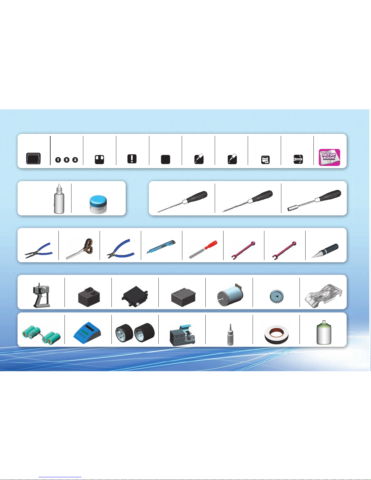
SYMBOLS USED
TOOLS REQUIRED
TOOLS REQUIREDEQUIPMENT INCLUDED
EQUIPMENT REQUIRED
L=R
2x
CA
OIL
Part bags
used
Assemble left and
right sides the
same way
Assemble in the
specified order
Pay attention
here
Assemble as many
times as specified
(here twice)
Apply CA glue Apply oil
05
Apply grease Ensure smooth
non-binding
movement
Follow Set-up
Book
Side Cutters Hobby Knife File Turnbuckle 4mm
(HUDY #181040)
Turnbuckle 3mm
(HUDY #181030)
Reamer
(HUDY #107600)
Pliers
Allen Wrench 1.5mm
(HUDY #111540)
Allen Wrench 2.0mm
(HUDY #112040)
Socket Driver 5.5mm
(HUDY #170055)
1.5 mm
2.0 mm
5.5 mm
Scissors
Transmitter Steering ServoReceiver
Lexan PaintBattery Charger Front & Rear Tires Bearing Oil
(HUDY #106230)
Speed Controller
Tire Truer
(HUDY #102003)
4-cell Battery Pack
Pinion Gear and Setscrew BodyshellElectric Motor
Fibre Tape
(HUDY #107870)
Page 4
4
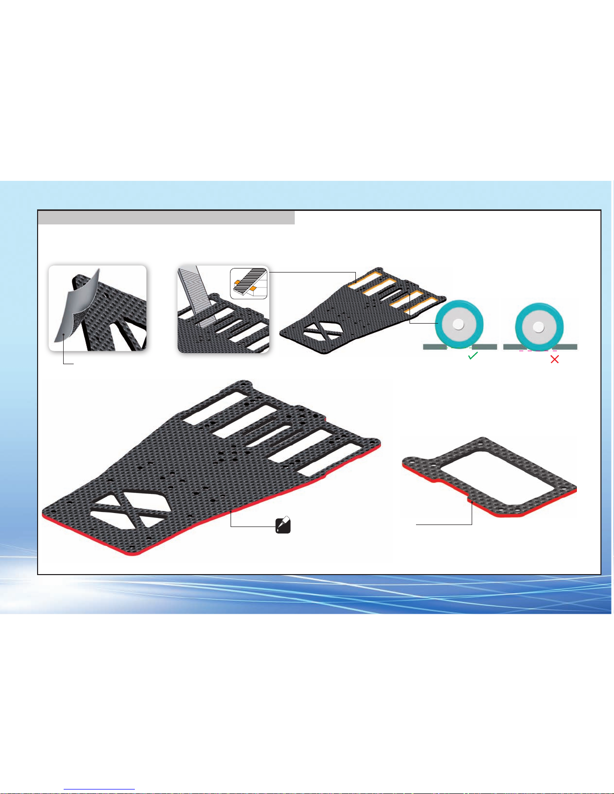
GRAPHITE PARTS PREPARATION
CORRECT
INCORRECT
Lightly file edges of battery slots to remove sharp edges.
Do not file battery slots too much, or batteries
may protrude below the chassis bottom.
To protect and seal edges of graphite parts, sand edges smooth and then apply CA glue.
Fine sandpaper
Use fine sandpaper to sand smooth
the edges of all graphite parts.
CA
PREPARE ALL GRAPHITE PARTS
Apply CA glue to all adges of the graphite parts.
Page 5
5
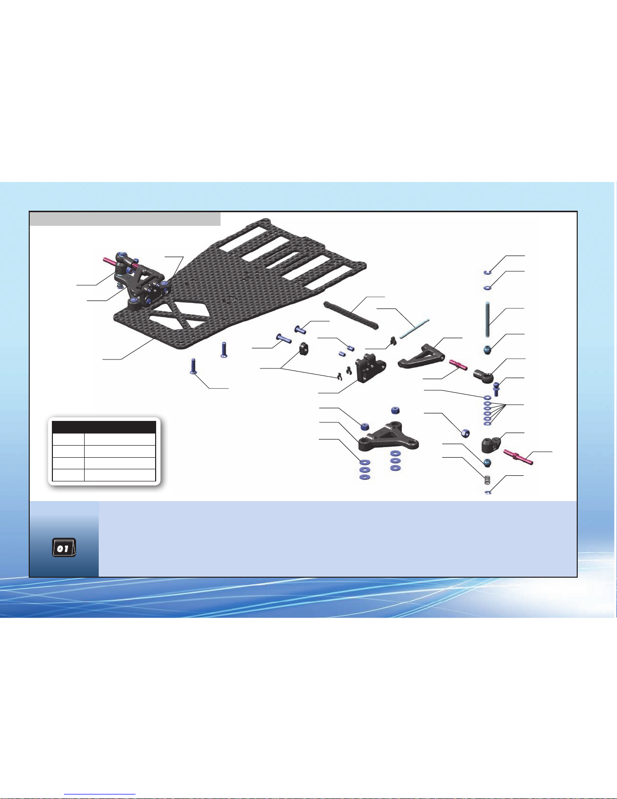
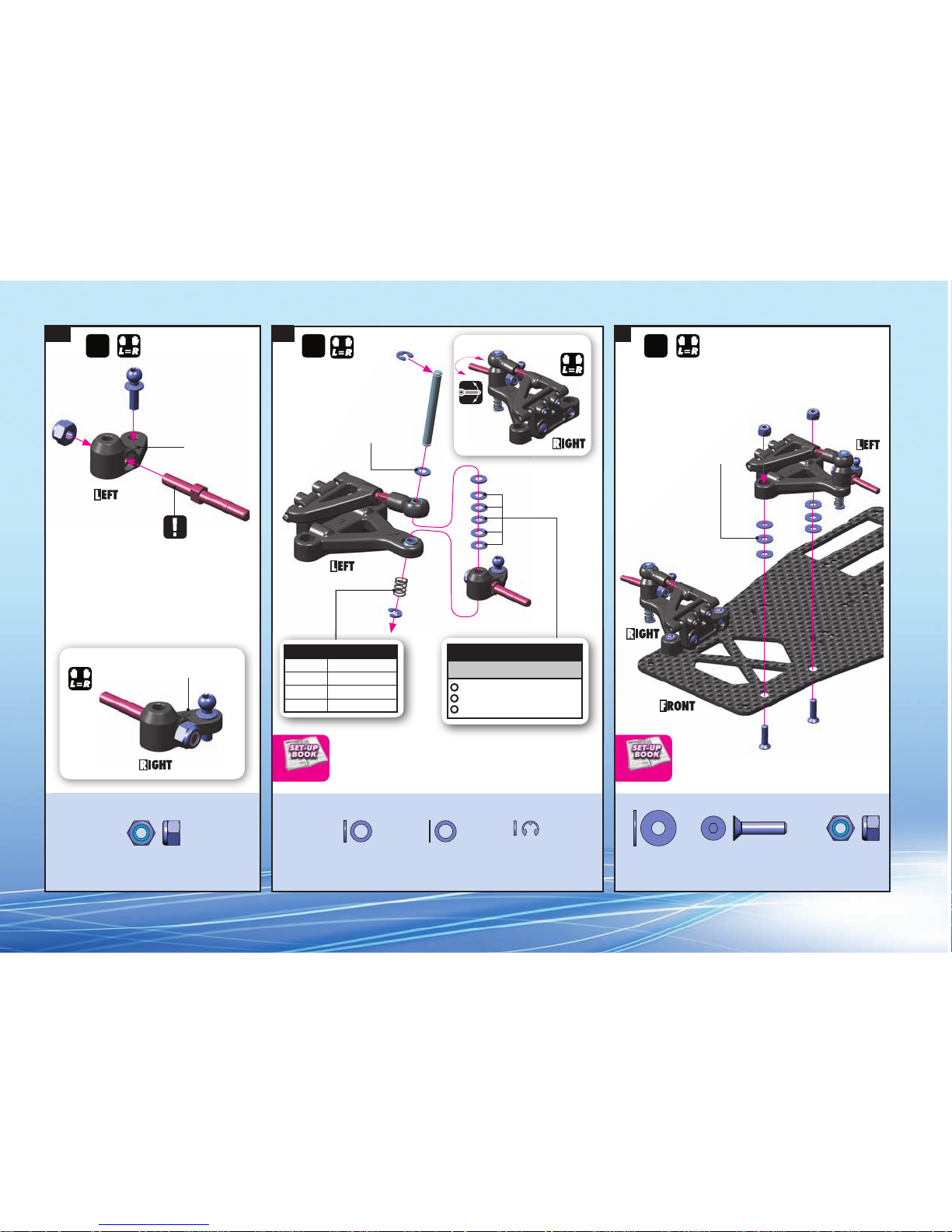
1. FRONT SUSPENSION
FRONT COIL SPRINGS
#372180 C=3.5 - GOLD (standard)
#372181
C=4.0 - SILVER (option)
#372182 C=5.0 - BLACK (option)
#372183 C=6.0 - GREY (option)
372180
372020
372620
371100
372315
902312
901304
960031
372290
960031
377220
372315
372120
372291
373240
BAG
903312
902308
965019
372085
372290
372280
372130
373240
965019
372130
372650
964032
372220
375220
371100 XII CHASSIS - 2.0MM GRAPHITE
372010 COMPOSITE FRONT UPPER ARM MOUNT - RIGHT
372020 COMPOSITE FRONT UPPER ARM MOUNT - LEFT
372085 FRONT BRACE - GRAPHITE 2.0MM
372110 COMPOSITE SUSPENSION ARM - FRONT LOWER - RIGHT
372120 COMPOSITE SUSPENSION ARM - FRONT LOWER - LEFT
372130 COMPOSITE FRONT UPPER SUSPENSION ARM & BALL JOINT
372180 FRONT COIL SPRING 3.6x6x0.5MM; C=3.5 - GOLD (2)
372210 COMPOSITE STEERING BLOCK - RIGHT
372220 COMPOSITE STEERING BLOCK - LEFT
372280 KING PIN (2)
372290 ALU SHIM 3.2x4.8x0.5 (4)
372291 ALU SHIM 3.1x8x0.5 (4)
372315 COMPOSITE ECCENTRIC BUSHINGS + CASTER CLIPS (2)
372620 ADJ. TURNBUCKLE M3x17 MM - HUDY SPRING STEEL™ (2)
372650 BALL-END 4.2MM - THREADED - HUDY SPRING STEEL™ (2)
373240 PIVOTBALL UNIVERSAL 6.0 MM - HUDY SPRING STEEL (2)
375220 FRONT WHEEL AXLE - HUDY SPRING STEEL (2)
372210
372110
372010
377220 FRONT UPPER PIVOT PIN 2x31MM (2)
901304 HEX SCREW SB M3x4 (10)
902308 HEX SCREW SH M3x8 (10)
902312 HEX SCREW SH M3x12 (10)
903312 HEX SCREW SFH M3x12 (10)
960031 ALU NUT M3 (10)
964032 WASHER S 3.2 x 4.8 x 0.2 (10)
965019 E-CLIP 1.9 (10)
Page 6
6
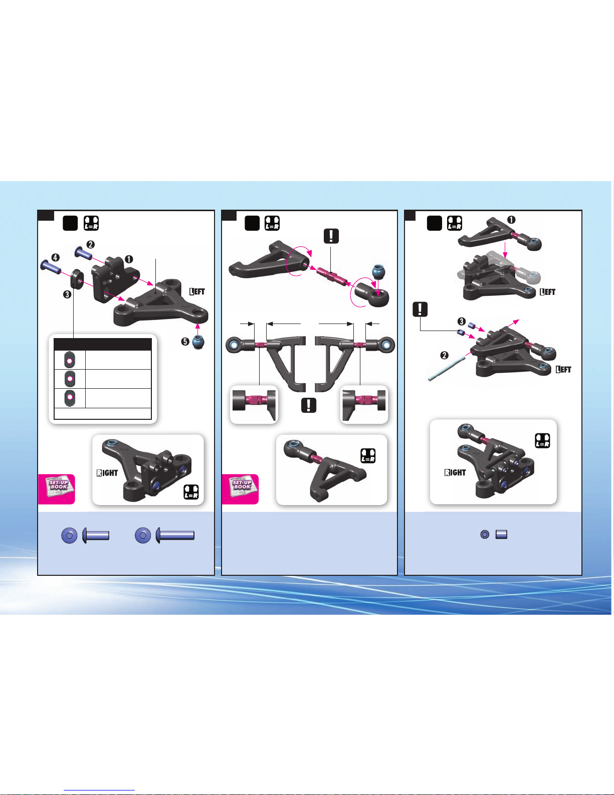
1. 2. 3.
3x12
3x8
5.2mm 5.2mm
COMPLETED ASSEMBLY COMPLETED ASSEMBLY
COMPLETED ASSEMBLY
Marked “L“
NOTE ORIENTATION
Lightly tighten setscrews
NOTE
ORIENTATION
2x 2x 2x
REACTIVE CASTER SETTING
= 2.5°
= 5° INITIAL SETTING
= 7.5°
Use same bushings in left and right sides.
CASTER CAMBER
902308
SH M3x8
901304
SB M3x4
902312
SH M3x12
Page 7
7
4. 5. 6.
Marked “R“
Marked “L“
COMPLETED ASSEMBLY
NOTE ORIENTATION
The number of shims used
affects the ride height of the
car, so determine the proper
amount of shimming based
on your tire diameter.
Moves
freely
The number of shims used affects the
ride height of the car, so determine
the proper amount of shimming
based on your tire diameter.
For initial setting use 3.1x8x0.5
shims (3x)
2x 2x 2x
FRONT RIDE HEIGHT ADJUSTMENT
INITIAL SETTING
above upper arm (0.5mm)
above steering block (1.5mm)
beneath steering block (0mm)
COMPLETED ASSEMBLY
FRONT COIL SPRINGS
#372180 C=3.5 - GOLD
#372181 C=4.0 - SILVER
#372182 C=5.0 - BLACK
#372183 C=6.0 - GREY
0.5mm
0.5mm
0.2mm (5x)
RIDE HEIGHT RIDE HEIGHT
960031
ALU N M3
372290
S 3.2x4.8x0.5
964032
S 3.2x4.8x0.2
372291
S 3.1x8x0.5
965019
C 1.9
903312
SFH M3x12
960031
ALU N M3
Page 8
8
7. 8.
FRONT BRACES
#372080 ALU ACTIVE BRACE (option)
#372085
GRAPHITE BRACE (standard)
2mm
Loosen all M3x4 setscrews so you
can easily remove the pins.
Make sure that arm moves freely.
INITIAL SETTING
After inserting clips, carefully tighten all M3x4
setscrews so the pins will not move. Do not
overtighten or you may strip the plastic.
If the arm does not have
enough play, remove the
clips and thin the clips
slightly with sandpaper.
The arms must have free
movement and not bind.
1mm
0.5mm
2x
FRONT BRACE CASTER
Page 9
9
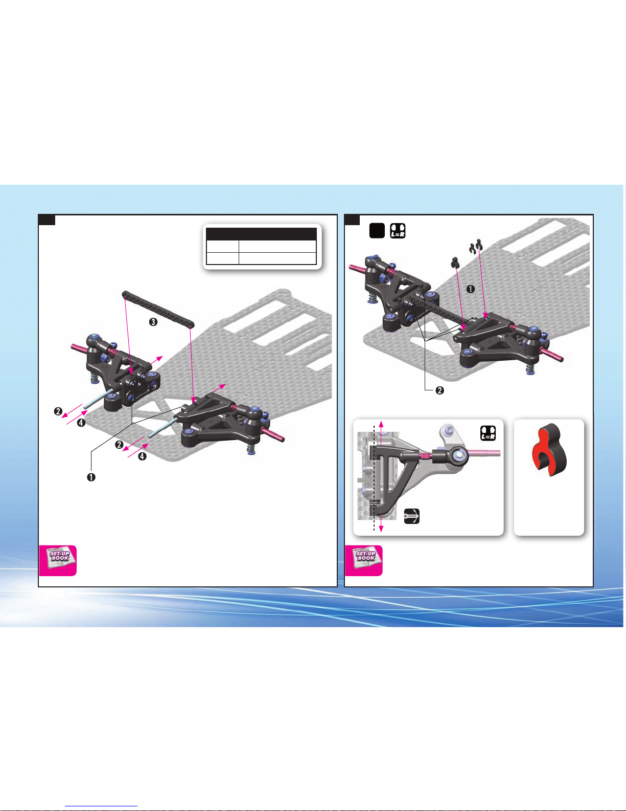
2. T-BAR ASSEMBLY
BAG
371180 FIBERGLASS T-BAR 1.5MM - WIDE
373060 COMPOSITE PIVOT MOUNTS - SET
373065 T-BAR PIVOTBALL - HUDY SPRING STEEL (2)
373510 ALU FRICTION DAMPER POST
373510
373065
373060
371180
902256
960031
373060
901305
373060
903314
901305 HEX SCREW SB M3x5 (10)
902256 HEX SCREW SH M2.5x6 (10)
903314 HEX SCREW SFH M3x14 (10)
960031 ALU NUT M3 (10)
Page 10

10
1.1 1.2
FIBERGLASS T-BAR
#371180 WIDE (standard)
#371181
NARROW (option)
T-BAR MOUNTING OPTION 1:
PRO Racing with 2 Pivotballs
T-BAR MOUNTING OPTION 2:
CLUB Racing with 1 Pivotball
T-BAR T-BAR
902256
SH M2.5x6
902256
SH M2.5x6
Page 11

11
2. 3.
Ensure free, smooth movement
without excessive freeplay.
These screws are used for tweak
adjustment. For more information
about tweak setting follow set-up
book.
1.9mm
1.9mm
Ensure the T-bar moves freely after assembly.
Lightly tighten the screws so
there is no free play, but do not
overtighten otherwise the balls
will not move freely.
This is only an ESTIMATED value;
make sure that the setscrews only
lightly touch the chassis.
INITIAL SETTING
TWEAK
901305
SB M3x5
903314
SFH M3x14
960031
ALU N M3
Page 12

12
3. REAR SUSPENSION
903306
902306
373060
373080
903310
371140
373030
372650
376300
301159
970048
903306
903306
373020
970048
372650
373520
902306
373540
903310
373010
903310
901304
903308
373520
373071
960031
960031
373580
373580
BAG
301159 ALU COUNTERSUNK SHIM (4)
371140 GRAPHITE 2.0MM REAR POD LOWER PLATE
372650 BALL-END 4.2MM - THREADED - HUDY SPRING STEEL™ (2)
373010 ALU REAR BULKHEAD - MOTOR (RIGHT)
373020 ALU REAR BULKHEAD - LEFT
373030 ALU REAR BULKHEAD BRACE
373060 COMPOSITE PIVOT MOUNTS - SET
373071 ALU REAR BRACE MOUNT (2)
373080 REAR BRACE - GRAPHITE 2.0MM
373520 COMPOSITE FRICTION DAMPER PAD (2)
373540 REAR POD UPPER PLATE - GRAPHITE 2.0MM
373580 FRICTION DAMPER PAD SPRING (2)
376300 COMPOSITE ANTENNA MOUNT
901304 HEX SCREW SB M3x4 (10)
902306 HEX SCREW SH M3x6 (10)
903306 HEX SCREW SFH M3x6 (10)
903308 HEX SCREW SFH M3x8 (10)
903310 HEX SCREW SFH M3x10 (10)
960031 ALU NUT M3 (10)
970048 O-RING 4.8x1.9 (10)
Page 13

13
1. 2. 3.
NOTE ORIENTATION
3x10
3x10
3x6
3x6
903306
SFH M3x6
903310
SFH M3x10
903310
SFH M3x10
960031
ALU N M3
902306
SH M3x6
903306
SFH M3x6
Page 14

14
4. 5. 6.
Do not fully tighten
the setscrew
Pod damping is controlled
by the amount of grease
used.
➊
➋
➌
➍
➎
➏
➐
➑
➒
Diff Grease
(HUDY #106211)
POD DAMPING
960031
ALU N M3
902306
SH M3x6
903306
SFH M3x6
970048
O 4.8x1.9
901304
SB M3x4
903308
SFH M3x8
Page 15

15
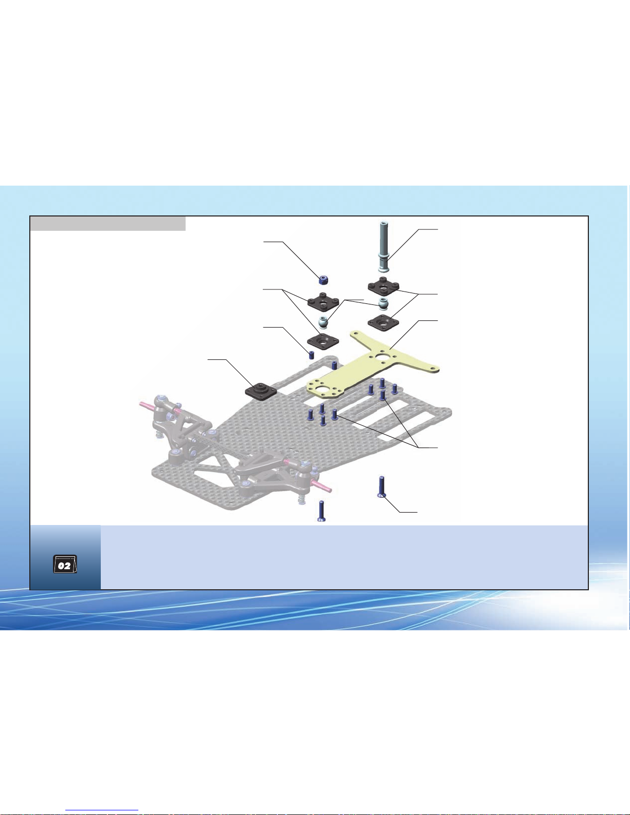
375030
375050
960031
930130
941438
375010
375090
951438
372070
375090
908258
375040
375080
930138
963030
941438
375896
375080
951438
3720
4. BALL DIFFERENTIAL
BAG
372070 COMPOSITE RIDE HEIGHT ADJUSTER SET (2)
375010 REAR AXLE SHAFT - GRAPHITE
375030 ALU REAR WHEEL HUB - RIGHT
375040 ALU REAR WHEEL HUB - LEFT
375050 ALU DIFF HUB
375080 D-LOCK DIFF PLATE (2)
375090 SET OF ALU SHIMS (0.5MM, 1.0MM, 2.0MM)
375896 COMPOSITE SPUR GEAR - 96T / 64P
908258 HEX SCREW SOCKET HEAD CAP M2.5x8 (10)
930130 CARBIDE BALL 3.175MM (12)
930138 CARBIDE BALL-BEARING AXIAL F3-8 3x8x3.5
941438 HIGH-SPEED BALL-BEARING 1/4“x3/8“x1/8“ RUBBER SEALED (2)
951438 BALL-BEARING 1/4“ x 3/8“ x 1/8“ FLANGED (2)
960031 ALU NUT M3 (10)
963030 CONE WASHER ST 3x8x0.5 (10)
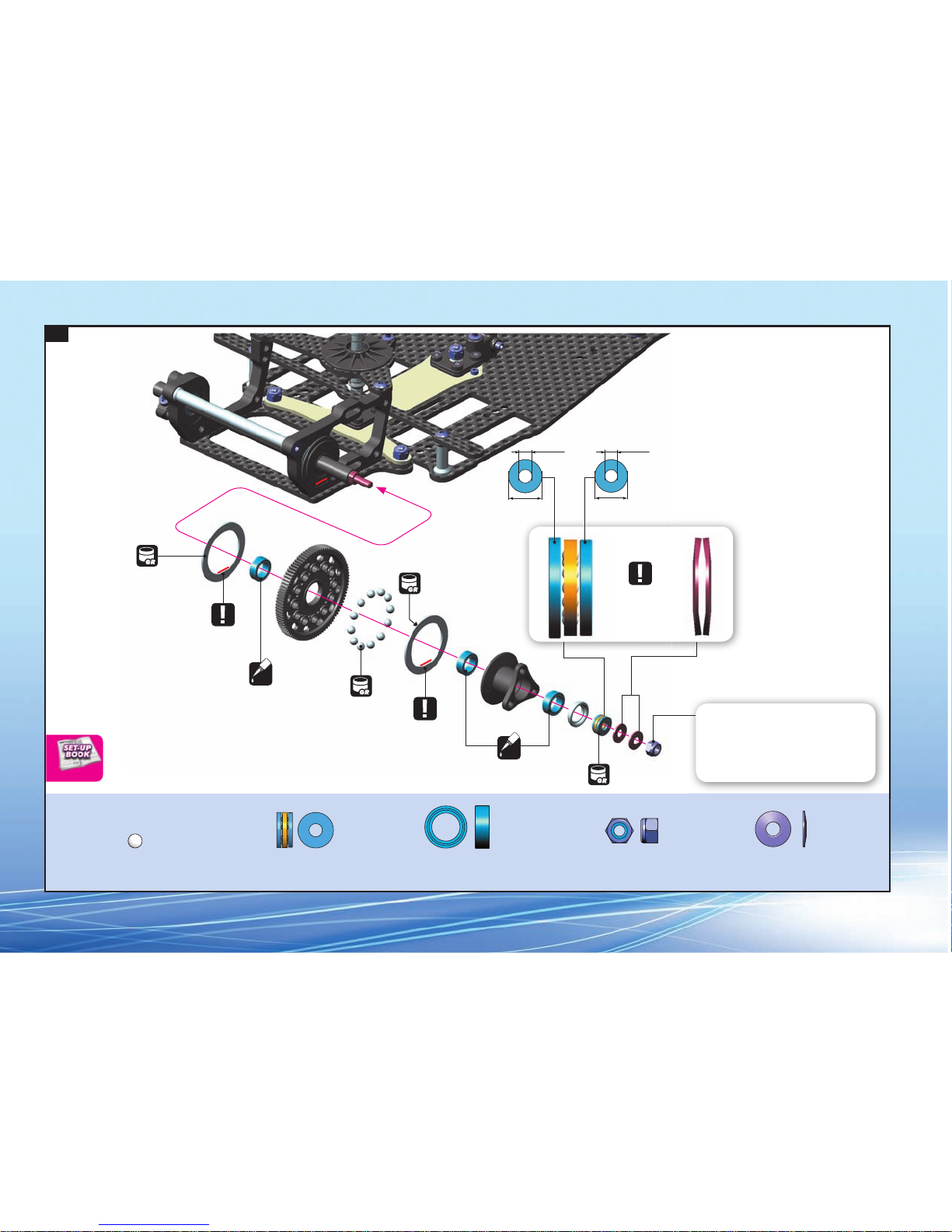
Page 16
16
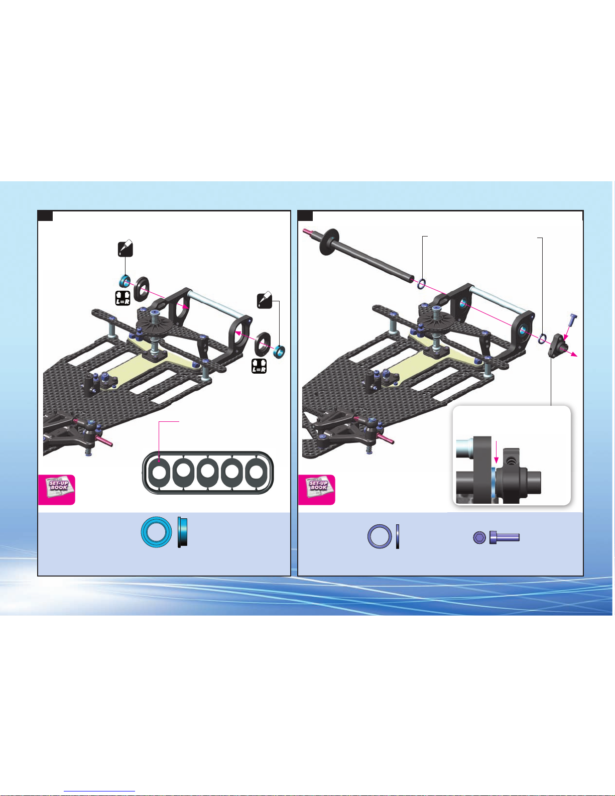
1. 2.
0 2.0 1.5 1.0 0.5
The axle must have a VERY small amount of
sideplay. If there is no side play, the axle may bind
in the ball-bearings and damage the bearings.
Use these Ride Height
Adjusters for initial assembly.
Use additional shims to widen the rear
track-width. Use the same shims on both sides.
For initial assembly use 6.4x8.4x1mm shims.
Bearing Oil
(HUDY #106230)
Bearing Oil
(HUDY #106230)
OIL
OIL
Flanged
Flanged
RIDE HEIGHT TRACK WIDTH
951438
BB 1/4“x3/8“x1/8“
375090
6.4x8.4x1.0
908258
SCH M2.5x8
Page 17
17
3.
NOTE
ORIENTATION
NOTE
ORIENTATION
NOTE
ORIENTATION
Diff Grease
(HUDY #106211)
Bearing Oil
(HUDY #106230)
Diff Grease
(HUDY #106211)
This nut affects the tightness and stiffness of the
rear differential.
Tighten the nut gently so the diff does not slip
under power, but do not overtighten or damage
to the diff balls and plates may occur.
OIL
Bearing Oil
(HUDY #106230)
OIL
Diff Grease
(HUDY #106211)
Diff Grease
(HUDY #106211)
8.0mm 7.8mm
3.0mm
3.2mm
DIFERENTIAL
930138
BA 3x8
941438
BB 1/4“x3/8“x1/8“
930130
B 3.1
963030
ST 3x8
960031
ALU N M3
Page 18

18
378010
378010
378060
971022
378030
378090
901303
378010
378050
378080
378020
378010
378040
378070
965015
SHOCK OILS
#359210 100cSt (option)
#359215
150cSt (option)
#359220 200cSt (option)
#359225 250cSt (option)
#359230 300cSt (option)
#359235 350cSt (standard)
#359240 400cSt (option)
#359245 450cSt (option)
5. SHOCK ABSORBER
BAG
378010 COMPOSITE SHOCK PARTS - FRAME
378020 ALU THREADED SHOCK BODY - HARDCOATED
378030 ALU SHOCK BODY CAP - LOWER
378040 ALU SHOCK ADJUSTABLE NUT
378050 ALU SHOCK BODY CAP - UPPER
378060 SHOCK SHAFT
378070 ALU SHOCK SPRING COLLAR
378080 SHOCK RUBBER MEMBRANE (2)
378090 SHOCK SPRING
901303 HEX SCREW SB M3x3 (10)
965015 E-CLIP 1.5 (10)
971022 SILICONE O-RING 2x2 (10)
Page 19

19
1. 2. 3.
Shock Oil
Shock Oil
OIL
OIL
Carefully remove the shock piston from the
frame, and remove all excess plastic fl ash
COMPLETED ASSEMBLY
965015
C 1.5
971022
O 2x2
Page 20

20
4.
➊➋➌➍➎➏
➐
Gently push the shock shaft
completely into the shock
body. Excess oil will flow
through the hole in the
shock cap.
Keep the shock shaft
pushed in the shock body
and tighten the shock cap
completely.
Tighten the cap fully but
do not overtighten or the
rubber membrane may be
damaged. Make sure that
there is no oil leakage
after the cap is tightened.
HALF TIGHTEN TIGHTEN FULLY
100%
Extend the shock shaft
completely. Fill the shock
body with the shock oil.
Move the shock shaft up and
down a few times to release
the air bubbles trapped
beneath the piston.
Orient the filled shock
vertically for several
minutes with the shock
shaft fully extended. The
remaining air bubbles will
release.
Install the shock membrane
into the groove in the
upper shock cap.
Gently place the shock cap
assembly onto the filled
shock body. Excess oil will
spill from the shock. Screw
the shock cap onto the body
by only a few turns, approx.
50%. Excess oil will flow
through the hole in the
shock cap.
3~5x
UP & DOWN
50%
Follow the steps below to set the shock.
Oil 350cSt
DEFAULT SHOCK SETTING
Page 21

21
5. 6.
5mm
COMPLETED ASSEMBLY
INITIAL SETTING
The length of the shock
absorber affects the amount
of rear downstop. To adjust,
thread the ball-joint on or
off the threaded post on the
bottom spring cap.
Press the collar FULLY onto the end of
the shock shaft and tighten the M3x3
setscrew.
For initial setting,
thread fully.
DOWNSTOP ADJUSTMENT
SHOCK
DOWNSTOP
901303
SB M3x3
Page 22

22
306131
NOT INCLUDED
309400
NOT INCLUDED
375390
951851
960031
981210
902308
NOT INCLUDED
309400
NOT INCLUDED
981210
903310372500
903308
372660
372610
951851
903305
371320
NOT INCLUDED
902308
371320
371200
903310
376310
376210
NOT INCLUDED
301159
372500
FROM SERVO
372650
372660
NOT INCLUDED
6. FINAL ASSEMBLY
BAG
301159 ALU COUNTERSUNK SHIM (4)
305968~88 PINION GEAR ALU HARD COATED 18~38T/64P
306131 SET OF BATTERY BACKSTOPS - V2
309400 BODY CLIP FOR 5MM BODY POST (8)
371200 COMPOSITE CHASSIS PROTECTOR (2)
371320 COMPOSITE BODY POST (2)
372500 COMPOSITE SERVO SAVER SET
372610 ALU ADJ. TURNBUCKLE M3x42 MM - SWISS 7075 T6 (2)
372650 BALL-END 4.2MM - THREADED - HUDY SPRING STEEL™ (2)
372660 COMPOSITE STEERING BALL-JOINT 4.2 MM (4)
375390 ALU HEX SCREW M3x8 FOR REAR WHEELS (6)
376210 COMPOSITE SERVO MOUNT (2)
376310 FIBERGLASS SOLID ANTENNA ROD + CAP
902308 HEX SCREW SH M3x8 (10)
903305 HEX SCREW SFH M3x5 (10)
903308 HEX SCREW SFH M3x8 (10)
903310 HEX SCREW SFH M3x10 (10)
960031 ALU NUT M3 (10)
981210 PIN 2x10 (10)
981851 BALL-BEARING 1/8“ x 5/16“ x 9/64“ FLANGED (2)
Page 23

23
1. 2. 3.
SERVO MOUNT SETS
#376210 COMPOSITE (standard)
#376215
GRAPHITE - MID-SIZE (option)
#376216 GRAPHITE - MICRO (option)
Futaba
INITIAL POSITION
Use the adapter that match
your servo.
We recommend using a micro
servo for 1/12 pan cars.
Note the orientation of
servo saver when servo is
in neutral.
90º
Hitec KO Propo
62mm
Left thread
Left thread
62mm
NOTE
ORIENTATION
2x
Servo
(Not included)
From servo
TOE
903308
SFH M3x8
903310
SFH M3x10
Page 24

24
4. 5. 6.
NOTE
ORIENTATION
NOTE
ORIENTATION
Note groove position
Note groove
position
2x 2x 2x
ACKERMANN
902308
SH M 3x8
903310
SFH M 3x10
981210
P 2x10
981210
P 2x10
Page 25

25
7. 8.
Adjust the gear mesh
so there is appropriate
space between the
spur gear and pinion
teeth. There should be
a very small amount of
freeplay.
The chassis is balanced for use with
a brushless motor. When a standard
brushed motor is used, we recommend
using additional shim(s) between the
motor and the bulkhead to balance the
weight properly.
Double-sided tape
(Not included)
After inserting the antenna rod, fully tighten both
setscrews. Do not overtighten or you may strip the plastic.
Receiver
(Not included)
Receiver wire
Pinion
(Not included)
Motor
(Not included)
Speed controller
(Not included)
➊
➋
➌
PINION GEARS ALU HARDCOATED
#305968 18T / 64P (option)
#305969 19T / 64P (option)
#305970 20T / 64P (option)
#305971 21T / 64P (option)
#305972 22T / 64P (option)
#305973 23T / 64P (option)
#305974 24T / 64P (option)
#305975 25T / 64P (option)
#305976 26T / 64P (option)
#305977 27T / 64P (option)
#305978 28T / 64P (option)
#305979 29T / 64P (option)
#305980 30T / 64P (option)
#305981 31T / 64P (option)
#305982 32T / 64P (option)
#305983 33T / 64P (option)
#305984 34T / 64P (option)
#305985 35T / 64P (option)
#305986 36T / 64P (option)
#305987 37T / 64P (option)
#305988 38T / 64P (option)
GEAR RATIO
902308
SH M 3x8
Page 26

26
9a. 9b.
BATTERY CONFIGURATION 2:
Rear Position
BATTERY CONFIGURATION 1:
Forward Position
INITIAL ASSEMBLY
BATTERY
POSITION
BATTERY
POSITION
903305
SFH M3x5
903305
SFH M3x5
Page 27

27
10.
Fibre tape
(HUDY #107870)
(Not included)
Battery Pack
(Not included)
Bearing Oil
(HUDY #106230)
OIL
Gently tighten the wheel nuts
so the wheel turns freely, but
without excessive axial play.
COMPLETED ASSEMBLY
Rear Wheels & Tires
(Not included)
Front Wheels & Tires
(Not included)
375390
ALU SCH M3x8
951851
BB 1/8“x5/16“x9/64“
960031
ALU N M3
Page 28

581703 9107018
 Loading...