

Page 1

Page 2

2
INTRODUCTION
The XRAY XB808 is a modern, high-competition premium luxury racing 1/8
nitro buggy that is the epitome of high-performance and fine distinctive
design. Your XB808 offers highest performance, responsive handling, and
traditionally exceptional XRAY quality, engineering, and design. The superb
craftsmanship and attention to detail are clearly evident everywhere on the
XRAY XB808.
XB808 was designed around a no compromise platform; the attention to
detail creates a low maintenance, extra long life nitro buggy. The ultra-low
center of gravity (CG) and optimized weight balance makes set-up, driving,
and maintenance easy and quick.
The XRAY XB808 was created by blending highest-quality materials and
excellent design. On high-speed flat tracks or bumpy tracks, whether driving
for fun or racing to win, the XB808 delivers outstanding performance, speed,
and precision handling.
We have made every effort to make these instructions as easy to understand as
possible. However, if you have any difficulties, problems, or questions, please
do not hesitate to contact the XRAY support team at info@teamxray.com.
Also, please visit our web site at www.teamxray.com to find the latest
updates, set-up information, option parts, and many other goodies. We
pride ourselves on taking excellent care of our customers.
SAFETY PRECAUTIONS
WARNING: This product contains a chemical known to the state of California to cause
cancer and birth defects or other reproductive harm.
CAUTION: CANCER HAZARD
Wash thoroughly after using. DO NOT use product while eating, drinking or using
tobacco products. May cause chronic effects to gastrointestinal tract, CNS, kidneys,
and blood. MAY CAUSE BIRTH DEFECTS.
When building, using and/or operating this model always wear protective glasses
and gloves.
Take appropriate safety precautions prior to operating this model. You are responsible
for this model‘s assembly and safe operation! Please read the instruction manual before
building and operating this model and follow all safety precautions. Always keep the
instruction manual at hand for quick reference, even after completing the assembly.
Use only genuine and original authentic XRAY parts for maximum performance. Using
any third party parts on this model will void guaranty immediately.
Improper operation may cause personal and/or property damage. XRAY and
its distributors have no control over damage resulting from shipping, improper
construction, or improper usage. XRAY assumes and accepts no responsibility for
personal and/or property damages resulting from the use of improper building
materials, equipment and operations. By purchasing any item produced by XRAY,
the buyer expressly warrants that he/she is in compliance with all applicable federal,
state and local laws and regulation regarding the purchase, ownership and use of the
item. The buyer expressly agrees to indemnify and hold harmless XRAY for all claims
resulting directly or indirectly from the purchase, ownership or use of the product. By
the act of assembling or operating this product, the user accepts all resulting liability.
If the buyer is not prepared to accept this liability, then he/she should return this kit in
new, unassembled, and unused condition to the place of purchase.
IMPORTANT NOTES – GENERAL
• This product is not suitable for children under 16 years of age without the direct
supervision of a responsible and knowledgeable adult.
• Carefully read all manufacturers warnings and cautions for any parts used in the
construction and use of your model.
• Assemble this kit only in places away from the reach of very small children.
• First-time builders and users should seek advice from people who have building
experience in order to assemble the model correctly and to allow the model to reach
its performance potential.
• Exercise care when using tools and sharp instruments.
• Take care when building, as some parts may have sharp edges.
• Keep small parts out of reach of small children. Children must not be allowed to put
any parts in their mouth, or pull vinyl bag over their head.
• Read and follow instructions supplied with paints and/or cement, if used (not
included in kit).
• Immediately after using your model, do NOT touch equipment on the model such
as the motor and speed controller, because they generate high temperatures. You
may seriously burn yourself seriously touching them.
• Follow the operating instructions for the radio equipment at all times.
• Do not put fi ngers or any objects inside rotating and moving parts, as this may
cause damage or serious injury as your fi nger, hair, clothes, etc. may get caught.
• Be sure that your operating frequency is clear before turning on or running your
model, and never share the same frequency with somebody else at the same time.
Ensure that others are aware of the operating frequency you are using and when
you are using it.
• Use a transmitter designed for ground use with RC cars. Make sure that no one
else is using the same frequency as yours in your operating area. Using the same
frequency at the same time, whether it is driving, fl ying or sailing, can cause loss of
control of the RC model, resulting in a serious accident.
• Always turn on your transmitter before you turn on the receiver in the car. Always
turn off the receiver before turning your transmitter off.
• Keep the wheels of the model off the ground when checking the operation of the
radio equipment.
• Disconnect the battery pack before storing your model.
• When learning to operate your model, go to an area that has no obstacles that can
damage your model if your model suffers a collision.
• Remove any sand, mud, dirt, grass or water before putting your model away.
• If the model behaves strangely, immediately stop the model, check and clear the
problem.
• To prevent any serious personal injury and/or damage to property, be responsible
when operating all remote controlled models.
• The model car is not intended for use on public places and roads or areas where its
operation can confl ict with or disrupt pedestrian or vehicular traffi c.
• Because the model car is controlled by radio, it is subject to radio interference from
many sources that are beyond your control. Since radio interference can cause
momentary loss of control, always allow a safety margin in all directions around the
model in order to prevent collisions.
• Do not use your model:
- Near real cars, animals, or people that are unaware that an RC car is being
driven.
- In places where children and people gather
- In residential districts and parks
- In limited indoor spaces
- In wet conditions
- In the street
- In areas where loud noises can disturb others, such as hospitals and
residential areas.
- At night or anytime your line of sight to the model may be obstructed or
impaired in any way.
To prevent any serious personal injury and/or damage to property, please be
responsible when operating all remote controlled models.
Failure to follow these instructions will be considered as abuse and/or neglect.
CUSTOMER SUPPORT
XRAY Europe
K Výstavisku 6992
91101 Trenčín
Slovakia, EUROPE
Phone: +421-32-7401100
Fax: +421-32-7401109
Email: info@teamxray.com
We have made every effort to make these instructions as easy to understand as possible.
However, if you have any diffi culties, problems, or questions, please do not hesitate to
contact the XRAY support team at info@teamxray.com. Also, please visit our Web site
at www.teamxray.com to fi nd the latest updates, set-up information, option parts, and
many other goodies. We pride ourselves on taking excellent care of our customers.
You can join thousands of XRAY fans and enthusiasts in our online community at:
www.teamxray.com
XRAY USA
RCAmerica, 167 Turtle Creek Boulevard Suite C
Dallas, Texas 75207
USA
Phone: (800) 519-7221 * (214) 744-2400
Fax: (214) 744-2401
Email: xray@rcamerica.com
IMPORTANT NOTES – NITRO ENGINES
• Always test the brakes and the throttle before starting your engine to avoid losing
control of the model.
• Make sure the air fi lter is clean and oiled.
• Never run your engine without an air fi lter. Your engine can be seriously damaged
if dirt and debris get inside the engine.
• For proper engine break-in, please refer to the manual that came with the engine.
• Do not run near open fl ames or smoke while running your model or while handling
fuel.
• Some parts will be hot after operation. Do not touch the exhaust or the engine until
they have cooled. These parts may reach 275°F during operation!
Page 3

3
IMPORTANT NOTES – ELECTRICAL
• Insulate any exposed electrical wiring (using heat shrink tubing or electrical tape)
to prevent dangerous short circuits. Take maximum care in wiring, connecting
and insulating cables. Make sure cables are always connected securely. Check
connectors for if they become loose. And if so, reconnect them securely. Never use
R/C models with damaged wires. A damaged wire is extremely dangerous, and can
cause short-circuits resulting in fi re. Please have wires repaired at your local hobby
shop.
• Low battery power will result in loss of control. Loss of control can occur due to a
weak battery in either the transmitter or the receiver. Weak running battery may also
result in an out of control car if your car‘s receiver power is supplied by the running
battery. Stop operation immediately if the car starts to slow down.
• When not using RC model, always disconnect and remove battery.
• Do not disassemble battery or cut battery cables. If the running battery short-circuits,
approximately 300W of electricity can be discharged, leading to fi re or burns. Never
disassemble battery or cut battery cables.
• Use a recommended charger for the receiver and transmitter batteries and follow
the instructions correctly. Over-charging, incorrect charging, or using inferior
chargers can cause the batteries to become dangerously hot. Recharge battery when
necessary. Continual recharging may damage battery and, in the worst case, could
build up heat leading to fi re. If battery becomes extremely hot during recharging,
please ask your local hobby shop for check and/or repair and/or replacement.
• Regularly check the charger for potential hazards such as damage to the cable,
plug, casing or other defects. Ensure that any damage is rectifi ed before using
the charger again. Modifying the charger may cause short-circuit or overcharging
leading to a serious accident. Therefore do not modify the charger.
• Always unplug charger when recharging is fi nished.
• Do not recharge battery while battery is still warm. After use, battery retains heat.
Wait until it cools down before charging.
• Do not allow any metal part to short circuit the receiver batteries or other electrical/
electronic device on the model.
• Immediately stop running if your RC model gets wet as may cause short circuit.
• Please dispose of batteries responsibly. Never put batteries into fi re.
WARRANTY
XRAY guarantees this model kit to be free from defects in both material and
workmanship within 30 days of purchase. The total monetary value under warranty
will in no case exceed the cost of the original kit purchased. This warranty does not
cover any components damaged by use or modifi cation or as a result of wear. Part
or parts missing from this kit must be reported within 30 days of purchase. No part
or parts will be sent under warranty without proof of purchase. Should you fi nd a
defective or missing part, contact the local distributor. Service and customer support
will be provided through local hobby store where you have purchased the kit,
therefore make sure to purchase any XRAY products at your local hobby store. This
model racing car is considered to be a high-performance racing vehicle. As such
this vehicle will be used in an extreme range of conditions and situations, all which
may cause premature wear or failure of any component. XRAY has no control over
usage of vehicles once they leave the dealer, therefore XRAY can only offer warranty
against all manufacturer‘s defects in materials, workmanship, and assembly at point
of sale and before use. No warranties are expressed or implied that cover damage
caused by what is considered normal use, or cover or imply how long any model cars‘
components or electronic components will last before requiring replacement.
Due to the high performance level of this model car you will need to periodically
maintain and replace consumable components. Any and all warranty coverage
will not cover replacement of any part or component damaged by neglect, abuse,
or improper or unreasonable use. This includes but is not limited to damage from
crashing, chemical and/or water damage, excessive moisture, improper or no
maintenance, or user modifi cations which compromise the integrity of components.
Warranty will not cover components that are considered consumable on RC vehicles.
XRAY does not pay nor refund shipping on any component sent to XRAY or its
distributors for warranty. XRAY reserves the right to make the fi nal determination of
the warranty status of any component or part.
Limitations of Liability
XRAY makes no other warranties expressed or implied. XRAY shall not be liable for any
loss, injury or damages, whether direct, indirect, special, incidental, or consequential,
arising from the use, misuse, or abuse of this product and/or any product or accessory
required to operate this product. In no case shall XRAY‘s liability excess the monetary
value of this product.
Take adequate safety precautions prior to operating this model. You are
responsible for this model’s assembly and safe operation.
Disregard of the any of the above cautions may lead to accidents, personal
injury, or property damage. XRAY MODEL RACING CARS assumes no
responsibility for any injury, damage, or misuse of this product during
assembly or operation, nor any addictions that may arise from the use
of this product.
All rights reserved.
QUALITY CERTIFICATE
XRAY MODEL RACING CARS uses only the highest quality materials, the best
compounds for molded parts and the most sophisticated manufacturing processes of
TQM (Total Quality Management). We guarantee that all parts of a newly-purchased
kit are manufactured with the highest regard to quality. However, due to the many
factors inherent in model racecar competition, we cannot guarantee any parts once
you start racing the car. Products which have been worn out, abused, neglected or
improperly operated will not be covered under warranty.
We wish you enjoyment of this high-quality and high-performance RC car and wish
you best success on the track!
In line with our policy of continuous product development, the exact specifications of the kit may vary. In the unlikely event of any
problems with your new kit, you should contact the model shop where you purchased it, quoting the part number. We do reserve all
rights to change any specification without prior notice. All rights reserved.
R/C & BUILDING TIPS
• Make sure all fasteners are properly tightened. Check them periodically.
• Make sure that chassis screws do not protrude from the chassis.
• For the best performance, it is very important that great care is taken to ensure the
free movement of all parts.
• Clean all ball-bearings so they move very easily and freely.
• Tap or pre-thread the plastic parts when threading screws.
• Self-tapping screws cut threads into the parts when being tightened. Do not use
excessive force when tightening the self-tapping screws because you may strip out
the thread in the plastic. We recommended you stop tightening a screw when you
feel some resistance.
• Ask your local hobby shop for any advice.
Please support your local hobby shop. We at XRAY Model Racing Cars support all local
hobby dealers. Therefore we ask you, if at all possible, to purchase XRAY products at
your hobby dealer and give them your support like we do. If you have diffi culty fi nding
XRAY products, please check out www.teamxray.com to get advice, or contact us via
email at info@teamxray.com, or contact the XRAY distributor in your country.
IMPORTANT NOTES – NITRO FUEL
• Handle fuel only outdoors. Never handle nitro fuel indoors, or mix nitro fuel in a
place where ventilation is bad.
• Only use nitro fuel for R/C models. Do not use gasoline or kerosene in R/C models
as it may cause a fi re or explosion, and ruin your engine.
• Nitro fuel is highly infl ammable, explosive, and poisonous. Never use fuel indoors
or in places with open fi res and sources of heat.
• Always keep the fuel container cap tightly shut.
• Always read the warning label on the fuel container for safety information.
• Nitro-powered model engines emit poisonous vapors and gasses. These vapors irritate
eyes and can be highly dangerous to your health. We recommend wearing rubber or vinyl
gloves to avoid direct contact with nitro fuel.
• Nitro fuel for RC model cars is made of the combination of the methyl alcohol,
castor or synthetic oil, nitro methane etc. The fl ammability and volatility of these
elements is very high, so be very careful during handling and storage of nitro fuel.
• Keep nitro fuel away from open fl ame, sources of heat, direct sunlight, high
temperatures, or near batteries.
• Store fuel in a cool, dry, dark, well-ventilated place, away from heating devices,
open fl ames, direct sunlight, or batteries. Keep nitro fuel away from children.
• Do not leave the fuel in the carburetor or fuel tank when the model is not in use.
There is danger that the fuel may leak out.
• Wipe up any spilled fuel with a cloth.
• Be aware of spilled or leaking fuel. Fuel leaks can cause fi res or explosions.
• Do not dispose of fuel or empty fuel containers in a fi re. There is danger of
explosion.
Page 4
4
SYMBOLS USED
L=R
2x
CA
OIL
Part bags used Assemble left and
right sides the
same way
Assemble in the
specified order
Pay attention
here
Assemble as
many times
as specified
(here twice)
Apply instant
glue
Cut off shadded
portion
Cut off
remaining
material
Tighten screw
gently
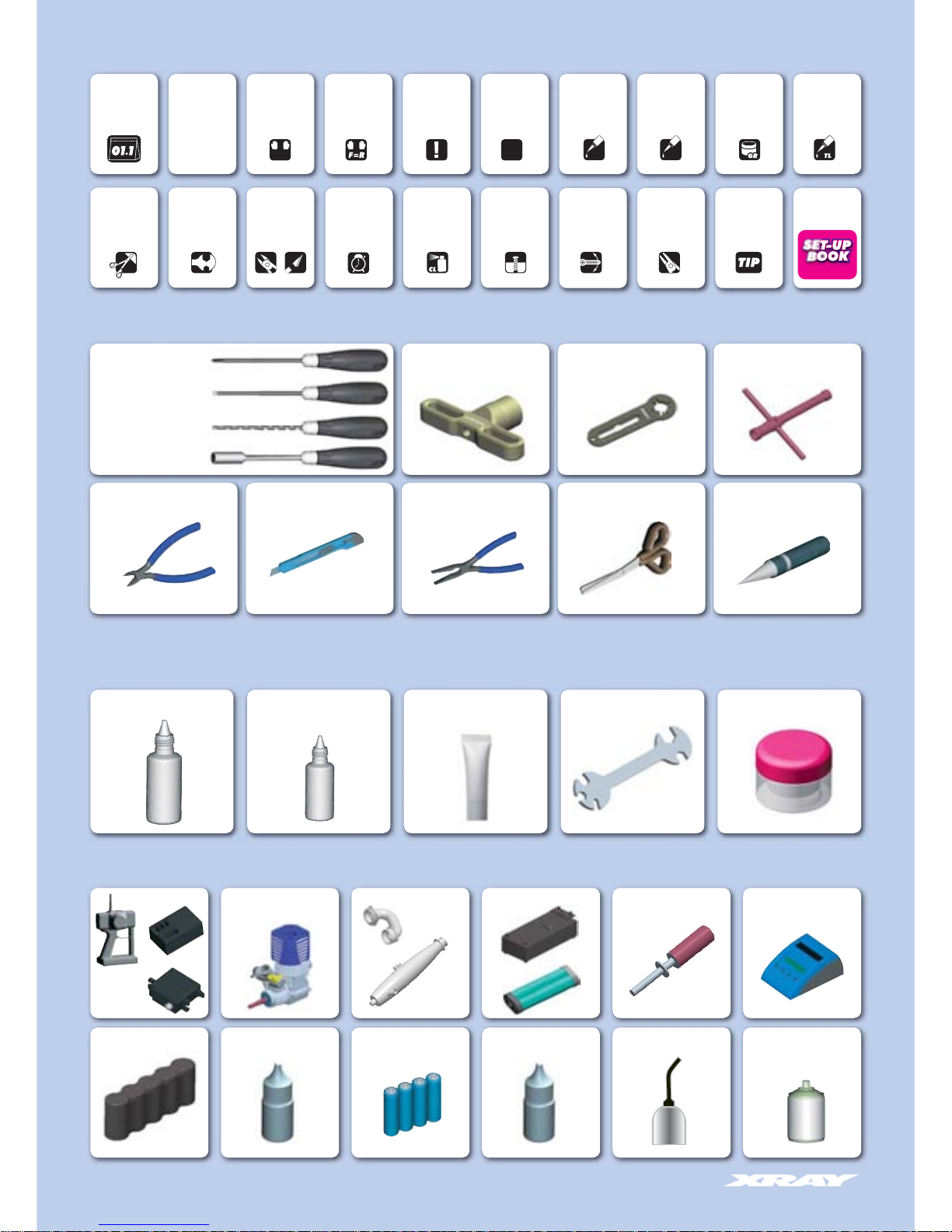
TOOLS REQUIRED
EQUIPMENT REQUIRED
TOOLS & EQUIPMENT INCLUDED
Assemble front
and rear the same
way
Apply oil
Use special
tool
Silicone Shock Oil Silicone Diff Oil Air Filter Oil
Receiver Pack
Transmitter
.21 Engine Manifold
Exhaust
Glow Plug IgniterStarter Box & Battery Pack
Steering and
Throttle Servos
Battery Charger
Receiver
Lexan PaintFuel
Special Tool for all turnbuckles, nuts
CA Glue
Phillips 5.0mm
(HUDY #165049)
Socket 5.0 / 5.5mm
(HUDY #170058/#170059)
Allen 1.5 / 2.0 / 2.5mm
(HUDY #111549/#112049/#112549)
17mm Wheel Nut Tool
(HUDY #107570)
Side Cutters Hobby Knife Body Reamer
(HUDY #107600)
Cross wrench
(HUDY #107581)
Flywheel Tool
(HUDY #182010)
ScissorsNeedle Nose Pliers
➊➋➌
Apply grease Apply
threadlock
Ensure smooth
non-binding
movement
Use pliers Follow tip here
ARM REAMER 3mm/4mm
(HUDY #107633/#107634)
Graphite Grease
(HUDY #106210)
Transmitter Batteries
Threadlock
Follow Set-Up
Book
Use cleaner
GEAR DIFF
Time
Page 5
5
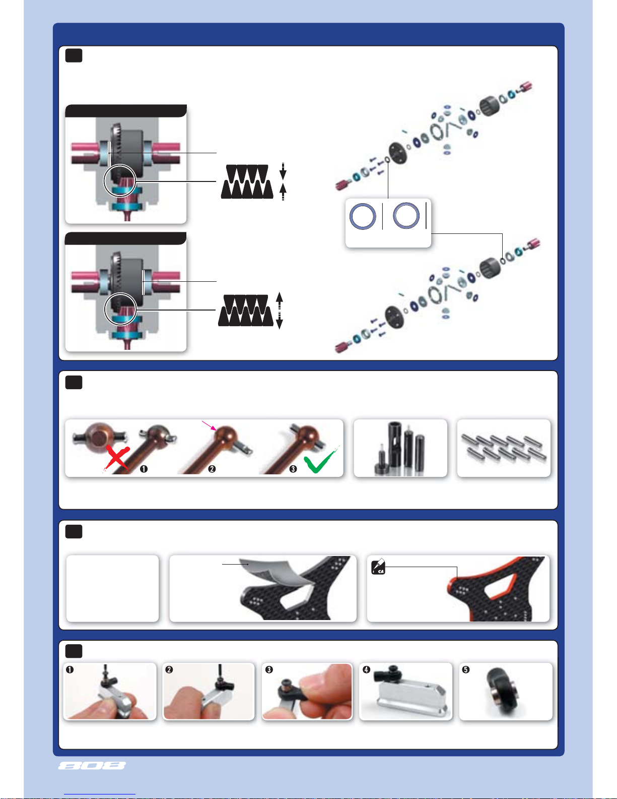
808 TECH TIPS
962080
S 8x0.1
962081
S 8x0.2
TIP
Tighten screw until pivot ball
is tight against block.
Lift ball joint until it snaps into
place over pivot ball. Ball joint
should move freely.
The fi nished joint. Loosen and remove screw.
INSTALLING PIVOT BALLS INTO COMPOSITE BALL-JOINTS
Place the pivot ball on the ball joint
and use a screw to tighten it to an
engine mount or some other part.
Before fi lling in the differentials with oil we suggest fi rst to check the gear mesh as below. If there is too much or too little diff side play, this may
create non-optimal gear mesh between the diff gear and the pinion drive gear. This is easily resolved by inserting 1 or 2 of the included thin
shims behind a diff outdrive ball-bearing, depending on how much play there is.
FRONT & REAR DIFF GEAR MESH ADJUSTMENT
THE LOCATION OF THE SHIM(S) DEPENDS ON WHETHER YOU ARE TRYING TO CLOSE OR OPEN THE GAP:
To close a wide gap:
add 1 or 2 shims against
diff spur gear
TO CLOSE A WIDE GAP
TO OPEN A NARROW GAP
To open a narrow gap:
add 1 or 2 shims on the
other side of the diff, away
from spur gear
#962080 WASHER S 8 x 0.1 mm (10)
#962081 WASHER S 8 x 0.2 mm (10)
TIP
insert shim(s) here
insert shim(s) here
DRIVE SHAFT PINS SERVICING
TIP
To enjoy the longest possible lifespan of the drive shafts and diff outdrives, it is extremely important to properly service the drive shaft pins.
Inspect the pins after every 3 hours of runtime. If the pins show any wear, replace them with new pins.
For easy and comfortable drive pin
replacements use #106000 HUDY
Drive Pin Replacement Tool.
To replace the worn pins use only
the premium HUDY drive pins
#106050.
GRAPHITE PARTS PROTECTION
TIP
Follow this tech tip to protect the graphite parts.
Fine sandpaper
Use fi ne sandpaper
to sand smooth the
edges of all graphite
parts.
Apply CA glue to all edges
of the graphite parts.
Protect all XB808
Graphite Parts:
• Front shock tower
• Rear shock tower
• Steering plate
• Radio plate
Do not use drive shafts
when the pins are worn.
Press out the worn pins. Press in new pins and
regularly inspect for
wear.
CLOSE A WIDE GAP
OPEN A NARROW GAP
Page 6
6
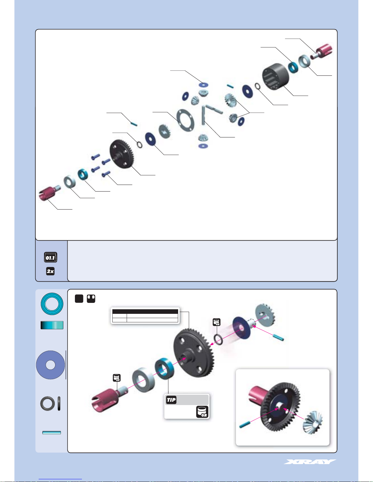
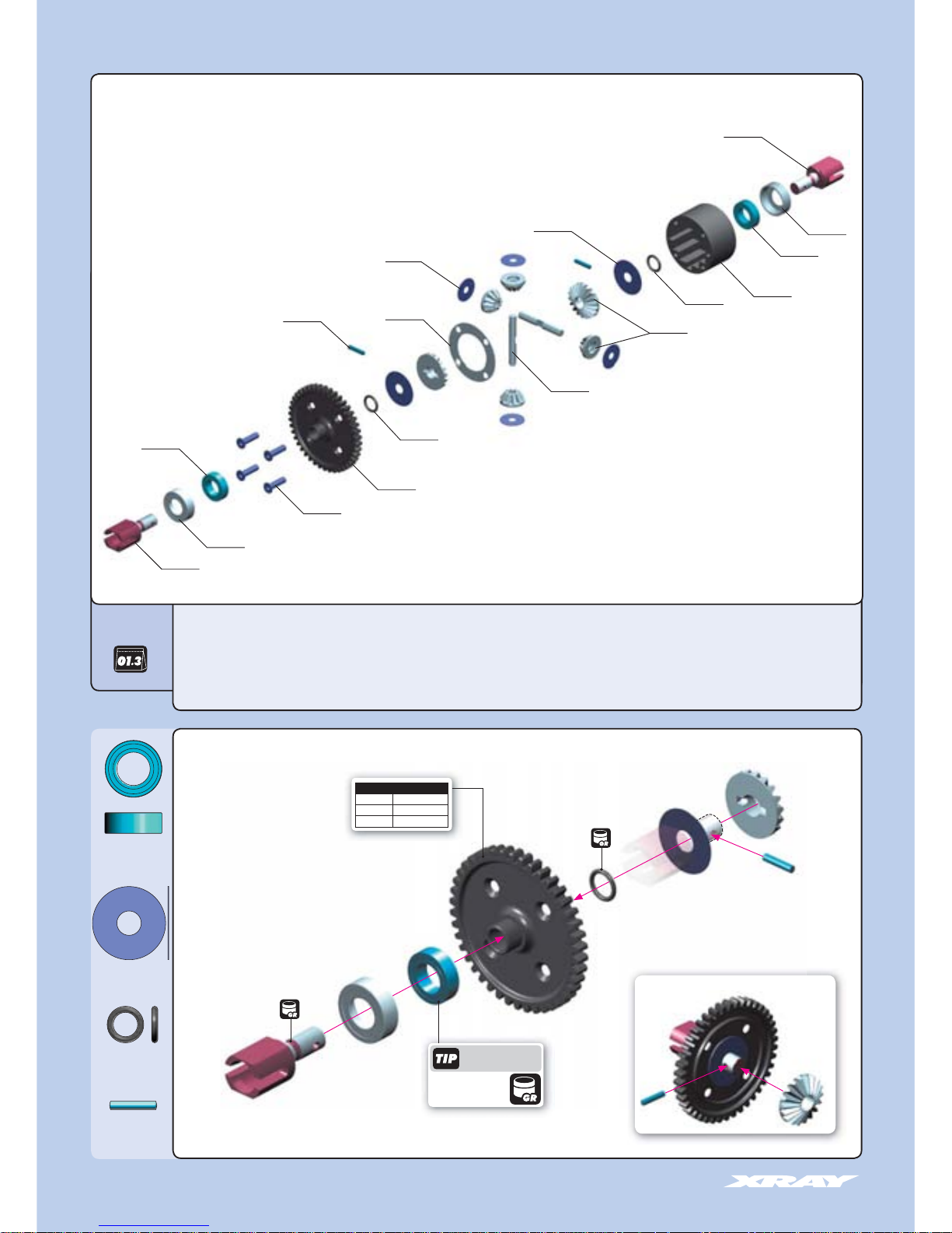
1. FRONT & REAR DIFFERENTIALS
2x
F=R
STEP DETAIL
➊
➋
➌
➍
➎
➏
➏➐
➐
35 2070 XB808 COMPOSITE BEARING HUB FOR DIFF (4)
35 5001 XB808 FRONT/REAR DIFFERENTIAL - SET
35 5020 DIFFERENTIAL CASE
35 5030 STEEL DIFF BEVEL & SATELLITE GEARS (2+4)
35 5043 FRONT/REAR DIFF LARGE BEVEL GEAR 43T - HUDY STEEL
35 5062 XB808 FRONT/REAR DIFF OUTDRIVE ADAPTER (2) HUDY SPRING STEEL™
35 5080 DIFF PIN (2)
35 5090 DIFF GASKET (4)
90 3312 HEX SCREW SFH M3x12 (10)
94 0814 HIGH-SPEED BALL-BEARING 8x14x4 BLUE COVERED (2)
96 4030 WASHER S 3.5x12x0.2 (10)
96 4060 WASHER S 6x18x0.2 (10)
97 1060 SILICONE O-RING 6x1.5 (10)
98 0212 PIN 2x11.6 (10)
BAGS
940814
352070
903312
355043
964060
355030
971060
355020
940814
355090
964030
980212
971060
355080
355062
352070
355062
Use HUDY Ball-Bearing
Grease for servicing:
#106220 - Standard
#106221 - Extra
#106222 - Premium
940814
BB 8x14x4
964060
S 6x18x0.2
971060
O 6x1.5
980212
P 2x11.6
Graphite Grease
(HUDY #106210)
Graphite Grease
(HUDY #106210)
FRONT/REAR DIFF LARGE BEVEL GEAR
#355041
DIFF LARGE BEVEL GEAR 41T (OPTION)
#355043
DIFF LARGE BEVEL GEAR 43T (STANDARD)
➏
➐
Page 7
7
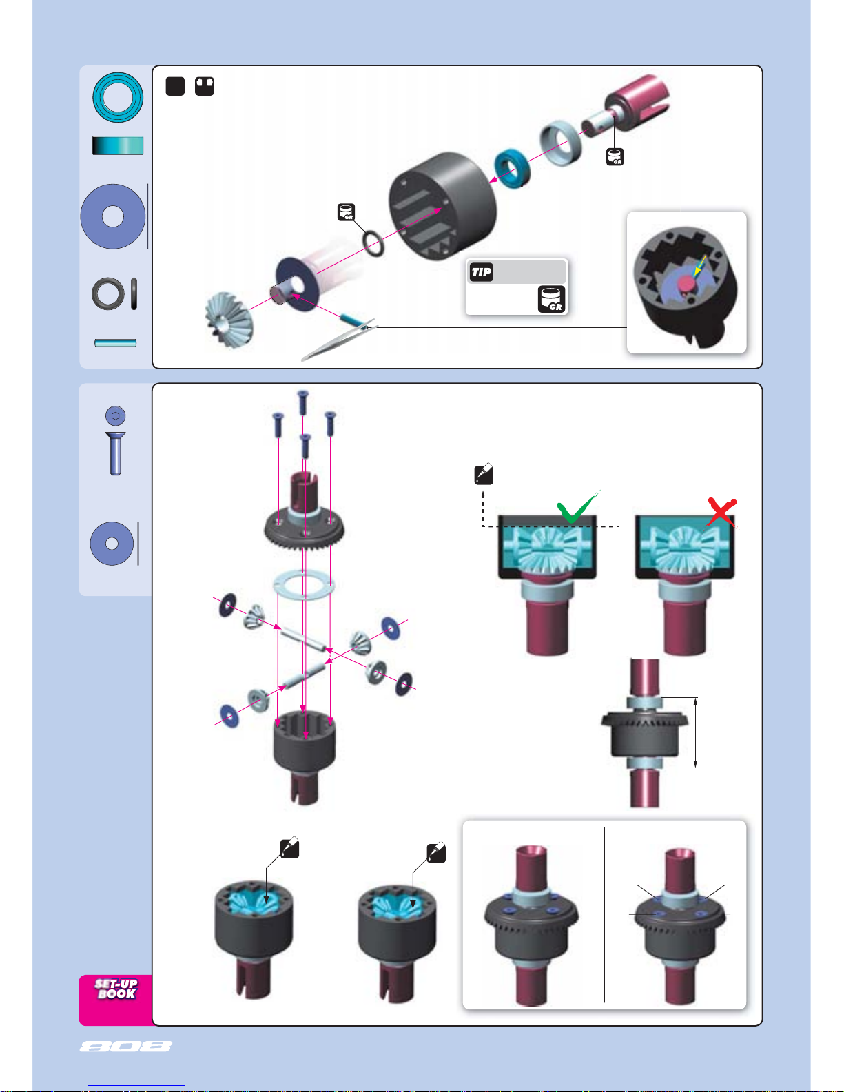
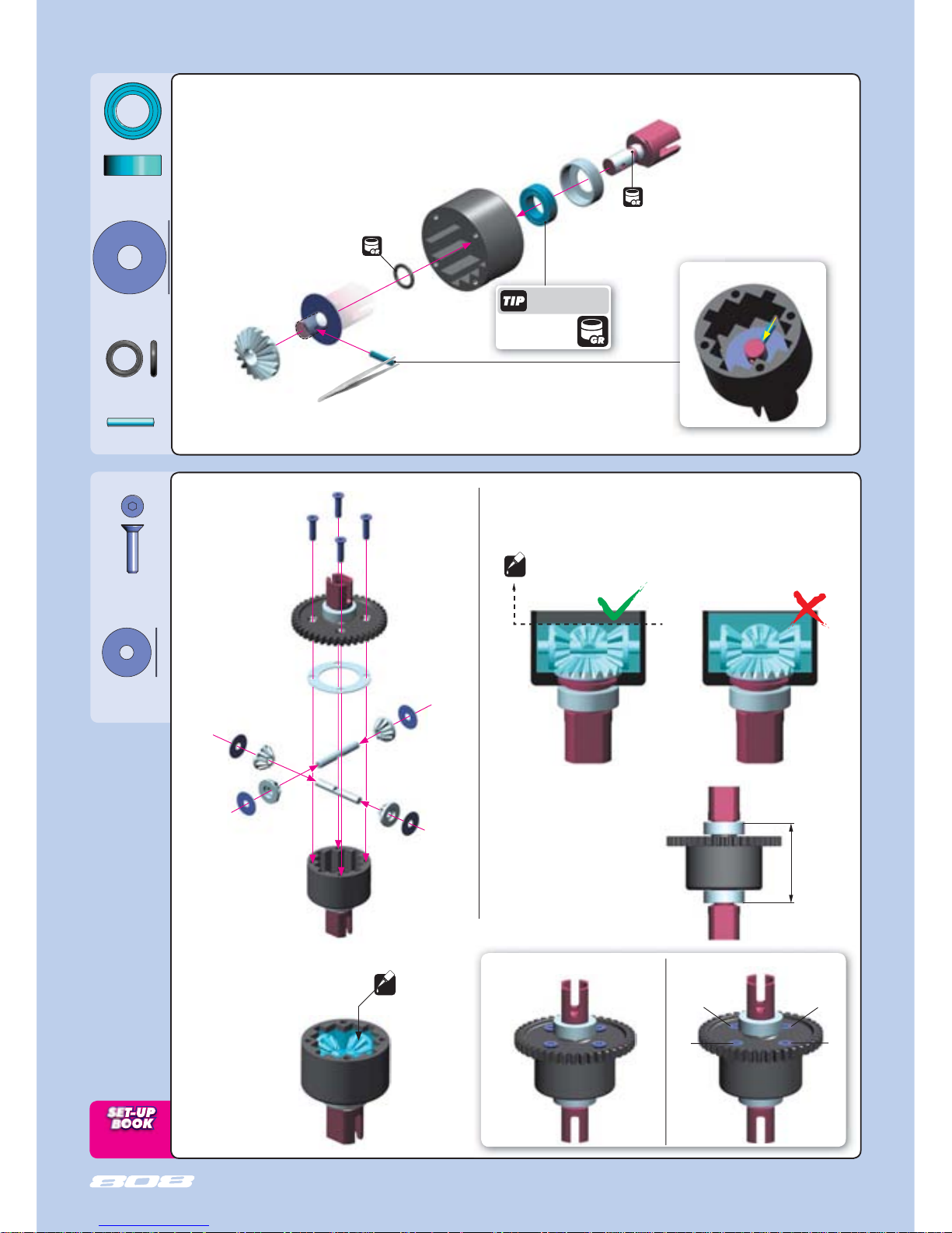
GEAR DIFF
VERY IMPORTANT!
Fill the differentials with oil just
above the satellite gears.
After assembly the differentials
should have a length of 32.6~32.7
mm measured from the ends of the
installed ball-bearings. If differentials
are longer, retighten the 4 screws
holding the crown gears.
32.6~32.7 mm
OIL
INCORRECT
CORRECT
FRONT & REAR DIFFERENTIALS
964030
S 3.5x12x0.2
903312
SFH M3x12
2x
F=R
OIL
Tighten the screws equally Finish tightening in this order
OIL
➊
➋
➌
➍
➎
➏
➊
➋
➌
➍
➐
940814
BB 8x14x4
964060
S 6x18x0.2
971060
O 6x1.5
980212
P 2x11.6
STEP DETAIL
Use HUDY Ball-Bearing
Grease for servicing:
#106220 - Standard
#106221 - Extra
#106222 - Premium
➏
Use these silicone oils included in the kit for initial settings:
Front diff:
5000cSt / Rear diff: 2000cSt
Rear diff:
Silicone oil 2000cSt
Fill just above the
satellite gears.
Front diff:
Silicone oil 5000cSt
Fill just above the
satellite gears.
Graphite Grease
(HUDY #106210)
Graphite Grease
(HUDY #106210)
Page 8
8
STEP DETAIL
CENTER DIFFERENTIAL
BAG
➊
➋
➌
➍
➎
➏
➏➐
➐
355070
940814
903312
355054
971060
355030
971060
355020
352070
940814
355090
964060
964030
980212
355080
355070
352070
35 2070 XB808 COMPOSITE BEARING HUB FOR DIFF (4)
35 5011 XB808 CENTRAL DIFFERENTIAL - SET
35 5020 DIFFERENTIAL CASE
35 5030 STEEL DIFF BEVEL & SATELLITE GEARS (2+4)
35 5054 CENTER DIFF SPUR GEAR 42T
35 5070 CENTER DIFF OUTDRIVE ADAPTER (2) - HUDY STEEL
35 5080 DIFF PIN (2)
35 5090 DIFF GASKET (4)
90 3312 HEX SCREW SFH M3x12 (10)
94 0814 HIGH-SPEED BALL-BEARING 8x14x4 BLUE COVERED (2)
96 4030 WASHER S 3.5x12x0.2 (10)
96 4060 WASHER S 6x18x0.2 (10)
97 1060 SILICONE O-RING 6x1.5 (10)
98 0212 PIN 2x11.6 (10)
Use HUDY Ball-Bearing
Grease for servicing:
#106220 - Standard
#106221 - Extra
#106222 - Premium
940814
BB 8x14x4
971060
O 6x1.5
964060
S 6x18x0.2
980212
P 2x11.6
Graphite Grease
(HUDY #106210)
Graphite Grease
(HUDY #106210)
CENTER DIFF SPUR GEAR
#355053 43T
(OPTION)
#355054 42T (STANDARD)
#355055 41T
(OPTION)
➏
➐
Page 9
9
GEAR DIFF
After assembly the differential should have
a length of 32.6~32.7 mm measured from
the ends of the installed ball-bearings. If
differential is longer, retighten the 4 screws
holding the spur gear.
32.6~32.7 mm
➊
➋
➍
➎
➏
➌
➐
940814
BB 8x14x4
971060
O 6x1.5
964060
S 6x18x0.2
Center diff:
Silicone oil 7000cSt
Fill just above the
satellite gears.
980212
P 2x11.6
VERY IMPORTANT!
Fill the differentials with oil just
above the satellite gears.
OIL
INCORRECT
CORRECT
CENTER DIFFERENTIAL
964030
S 3.5x12x0.2
903312
SFH M3x12
Tighten the screws equally Finish tightening in this order
OIL
➊
➋
➌
➍
STEP DETAIL
➏
Use HUDY Ball-Bearing
Grease for servicing:
#106220 - Standard
#106221 - Extra
#106222 - Premium
Use the following silicone oil included in the kit for initial setting:
Center diff:
7000cSt
Graphite Grease
(HUDY #106210)
Graphite Grease
(HUDY #106210)
Page 10
10
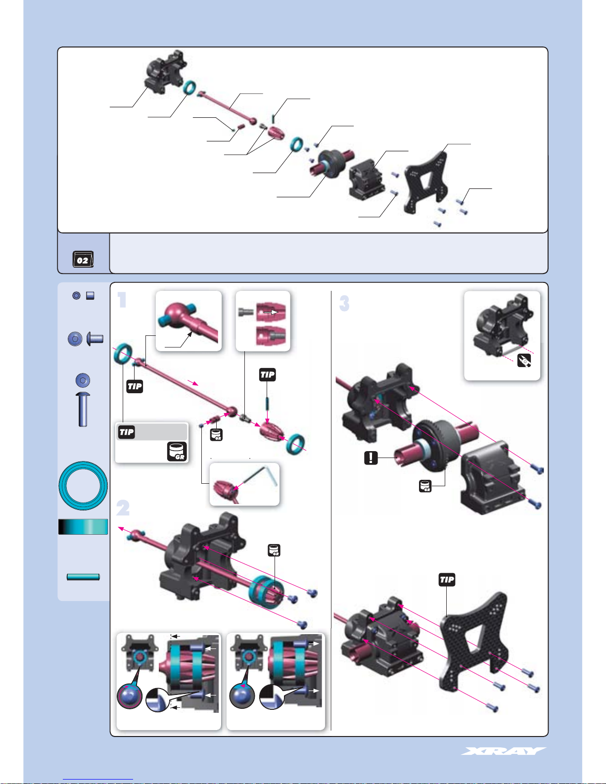
2. FRONT TRANSMISSION
Cut on both front
and rear bulkhead blocks
941319
BB 13x19x4
902305
SH 3x5
902312
SH 3x12
980263
P 2.5x13
Follow the TECH TIP on page
5 for drive shaft pin servicing
Follow the TECH TIP on page
5 to protect graphite parts
3x5
3x12
Replace this pin
when wear is
present
Graphite Grease
(HUDY #106210)
Graphite Grease
(HUDY #106210)
FRONT DIFF 5000 cSt
Graphite Grease
(HUDY #106210)
901303
SB 3x3
3x12
Loosen all 3 screws VERY SLIGHTLY
(approximately 1/12 of a turn). Pinion must turn freely.
➊
➋
➊
➋
DETAIL
step
step
step
DETAIL
➊
➋
➌
➍
➏
FRONT
DETAIL
Use HUDY Ball-Bearing
Grease for servicing:
#106220 - Standard
#106221 - Extra
#106222 - Premium
step
4
STEP DETAIL
➊
➐
902312
352092
352002
355001
FRONT DIFF
980263
355238
355421
941319
352002
355111
941319
902305
902312
35 2002 XB808 DIFF BULKHEAD BLOCK SET FRONT/REAR
35 2092 XB808 GRAPHITE FRONT SHOCK TOWER - CNC MACHINED 4 MM
35 5111 XB808 PINION GEAR 10T
35 5238 XB808 CVD DRIVE SHAFT COUPLING HUDY SPRING STEEL™
35 5421 XB808 FRONT CENTRAL CVD DRIVE SHAFT - HUDY SPRING STEEL™
90 1303 HEX SCREW SB M3x3 (10)
90 2305 HEX SCREW SH M3x5 (10)
90 2312 HEX SCREW SH M3x12 (10)
94 1319 HIGH-SPEED BALL-BEARING 13x19x4 RUBBER SEALED (2)
98 0263 PIN 2.5x13 (10)
BAG
Tighten screws fully. Make sure the
bearing seats properly in the bulkhead.
➎
STEP DETAIL
➎
901303
Use 1.5mm
Allen wrench
DETAIL
Page 11
11
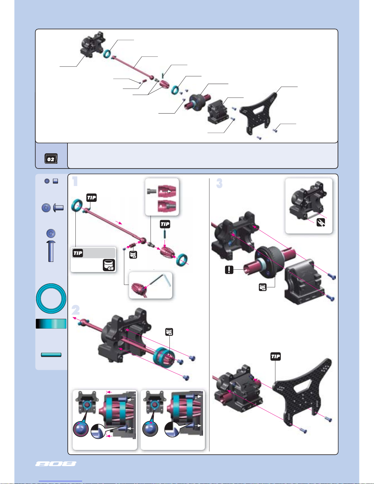
REAR TRANSMISSION
Cut on both front
and rear bulkhead blocks
REAR DIFF 2000 cSt
Follow the TECH TIP on page
5 to protect graphite parts
Graphite Grease
(HUDY #106210)
Follow the TECH TIP on page
5 for drive shaft pin servicing
3x5
Graphite Grease
(HUDY #106210)
941319
BB 13x19x4
902305
SH 3x5
902312
SH 3x12
980263
P 2.5x13
901303
SB 3x3
3x12
Loosen all 3 screws VERY SLIGHTLY
(approximately 1/12 of a turn). Pinion must turn freely.
➊
➋
➊
➋
Graphite Grease
(HUDY #106210)
DETAIL
step
step
4
BAG
35 2002 XB808 DIFF BULKHEAD BLOCK SET FRONT/REAR
35 3092 XB808 GRAPHITE REAR SHOCK TOWER - CNC MACHINED 3.5 MM
35 5111 XB808 PINION GEAR 10T
35 5238 XB808 CVD DRIVE SHAFT COUPLING - HUDY SPRING STEEL™
35 5621 XB808 REAR CENTRAL CVD DRIVE SHAFT - HUDY SPRING STEEL™
90 1303 HEX SCREW SB M3x3 (10)
90 2305 HEX SCREW SH M3x5 (10)
90 2312 HEX SCREW SH M3x12 (10)
94 1319 HIGH-SPEED BALL-BEARING 13x19x4 RUBBER SEALED (2)
98 0263 PIN 2.5x13 (10)
3x12
step
step
➊
➋
➌
➏
Use HUDY Ball-Bearing
Grease for servicing:
#106220 - Standard
#106221 - Extra
#106222 - Premium
STEP DETAIL
➊
➐
➎
STEP DETAIL
➎
Replace this pin
when wear is
present
➍
Use 1.5mm
Allen wrench
352002
355001
REAR DIFF
980263
941319
352002
941319
355238
902305
902312
902312
353092
355621
355111
901303
DETAIL
Tighten screws fully. Make sure the
bearing seats properly in the bulkhead.
DETAIL
Page 12
12
TOE-IN
ANTI-SQUAT
ROLL CENTER
909395
SS 3.5x45
909372
SS 3.5x22
FRONT VIEW
R
33 3450 ANTI-ROLL BAR BALL JOINT 5.8 MM (2)
35 2002 XB808 DIFF BULKHEAD BLOCK SET FRONT/REAR
35 2460 PIVOT BALL 5.8 (10)
35 2470 BALL JOINT 5.8 (8)
35 3114 XB808 COMPOSITE REAR LOWER SUSPENSION ARM
35 3302 XB808 COMPOSITE REAR LOWER SUSP. HOLDERS SET
35 3371 XB808 SET OF COMPOSITE LOWER ARM SHIMS
35 3486 XB808 REAR ANTI-ROLL BAR 2.6MM
35 7213 XB808 LOWER INNER PIVOT PIN SCREW 4MM (2)
90 1303 HEX SCREW SB M3x3 (10)
90 1305 HEX SCREW SB M3x5 (10)
90 1312 HEX SCREW SB M3x12 (10)
90 1408 HEX SCREW SB M4x8 (10)
90 2318 HEX SCREW SH M3x18 (10)
90 3308 HEX SCREW SFH M3x8 (10))
90 9372 SCREW PHILLIPS SS 3.5x22 (10)
90 9395 SCREW PHILLIPS SS 3.5x45 (10)
96 0040 NUT M4 (10)
BAG
3.5x22
3.5x45
REAR ANTI-ROLL BARS
#353482 2.2mm
(OPTION)
#353484 2.4mm
(OPTION)
#353486 2.6mm (STANDARD)
#353488 2.8mm
(OPTION)
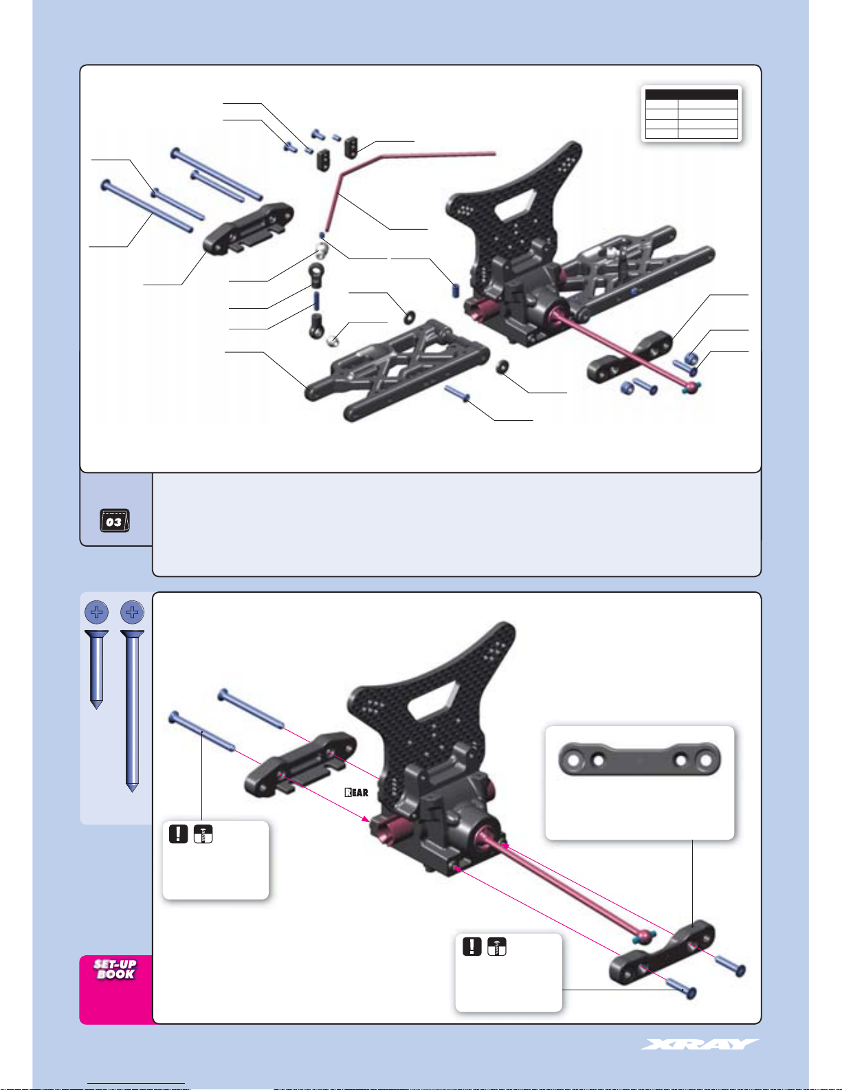
3. REAR SUSPENSION
333450
352470
353114
352460
960040
353302
909372
901303
353486
353371
901408
353371
902318
901305
903308
352002
909395
357213
353302
The composite suspension holders feature preset optimum
geometry 3° rear toe-in and 2° rear anti-squat.
Use optional adjustable suspension holders for further
geometry adjustment.
Do not overtighten the screws.
Overtightening may result in
composite suspension holder
deformation.
Do not overtighten the screws.
Overtightening may result in
composite suspension holder
deformation.
901312
Page 13

13
DOWNSTOP
WHEELBASE
ANTI-ROLL BAR
REAR SUSPENSION
901312
SB M3x12
901303
SB M3x3
902318
SH M3x18
903308
SFH M3x8
901305
SB M3x5
901408
SB M4x8
960040
N M4
➊
➋
➌
➍
3x5
3x8
L=R
4mm
DOWNSTOP SETTING
L=R
Loosen the 3x5 setscrew if the anti-
roll bar does not turn freely
4x8
Downstop screw
2mm
2mm
Do not overtighten the self-locking
nut. Overtightening may result in
suspension binding.
L=R
2x
3x12
1.5mm
6mm
Follow the TECH TIP on page
5 to install the pivot balls
3x3
L=R
Step check for free movement
➊
0mm
STEP DETAIL
➍
3x18
Step
➊
(HUDY #107634)
ARM REAMER
If the suspension arm does not
move freely use a HUDY Arm
Reamer to size the holes of the arms
Check for free
movement
REAR ARM
L=R
Ensure there is a little play
Ensure there is a little play
DETAIL
DETAIL
INITIAL POSITION
INITIAL POSITION
1
1
2
2
CORRECT
After tightening the
suspension pins the
suspension holders
will slightly bend
which is correct and
will not have any negative effect. However it is very
important to ensure that the suspension arm moves
freely with no binding. When tightening the selflocking nut, ensure that the thread on the pin goes
into the nylon insert inside the end of the nut.
Page 14

14
TRACK WIDTH
WHEELBASE
980317
P 3x17
941319
BB 13x19x4
901504
SB M5x4
980263
P 2.5x13
940814
BB 8x14x4
Use HUDY Ball-Bearing
Grease for servicing:
#106220 - Standard
#106221 - Extra
#106222 - Premium
➊
➋
ASSEMBLED VIEW
L=R
➌
➍
➑
➐
➏
➍
➎
4. REAR SUSPENSION
35 1301 XB808 BODY POSTS
35 2631 ADJ. TURNBUCKLE M5 L/R 64 MM - HUDY SPRING STEEL (2)
35 3131 XB808 REAR UPPER INNER CAMBER LINK BALL JOINT (2)
35 3152 XB808 REAR UPPER OUTER CAMBER LINK BALL JOINT (2)
35 3160 MOUNTING BALL 6.8 (4)
35 3170 PIVOT BALL 6.8 (4)
35 3351 XB808 COMPOSITE REAR HUB CARRIER
35 3370 XB808 SET OF COMPOSITE REAR HUB CARRIER SHIMS
35 3520 REAR WING POSTS
35 3559 COMPOSITE REAR WING MOUNT BRACE (2)
35 5211 XB808 CVD DRIVE AXLE - HUDY SPRING STEEL™
35 5221 XB808 CVD UNIVERSAL DRIVE SHAFT - HUDY SPRING STEEL™
35 5237 XB808 CVD DRIVE SHAFT COUPLING - HUDY SPRING STEEL™
35 5250 ALU WHEEL AXLE - HARD COATED (2)
35 7331 XB808 REAR LOWER OUTER PIVOT PIN SCREW 3MM (2)
90 1504 HEX SCREW SB M5x4 (10)
90 2310 HEX SCREW SH M3x10 (10)
90 2316 HEX SCREW SH M3x16 (10)
90 2318 HEX SCREW SH M3x18 (10)
90 2320 HEX SCREW SH M3x20 (10)
90 2322 HEX SCREW SH M3x22 (10)
90 5314 SCREW PHILLIPS 3.0x14 (10)
94 0814 HIGH-SPEED BALL-BEARING 8x14x4 BLUE COVERED (2)
94 1319 HIGH-SPEED BALL-BEARING 13x19x4 BLUE COVERED (2)
96 0030 NUT M3 (10)
98 0263 PIN 2.5x13 (10)
98 0317 PIN 3x17 (10)
BAG
2x
L=R
980317
355250
901504
353370
902322
941319
960030
902320
905314
960030
902320
353520
353559
352631
353160
353170
960030
351301
902318
960030
902310
902316
355211
355237
357331
355221
980263
353520
905314
940814
Ensure that the rear upright moves freely. If it does not move freely, use
sandpaper to thin both wheelbase adjustment shims.
Shims for wheelbase
adjustment
L=R
L=R
Graphite Grease
(HUDY #106210)
2mm
Check for free movement
353152
353131
353351
To tighten the setscrew you can also use HUDY
17mm Wheel Nut Tool #107570
3x17
2.5x13
8x14x4
13x19x4
Follow the TECH TIP on page 5
for drive shaft pin servicing
Do not overtighten the self-locking nut. Overtightening
may result in suspension binding.
(HUDY #107633)
If the rear upright does not
move freely, use a HUDY Arm
Reamer to resize the hole.
ARM REAMER
2mm
OFFSET WHEEL AXLES
#355250 0mm (STANDARD)
#355251 +1mm
(OPTION)
#355252 +2mm
(OPTION)
2.5mm
Page 15

15
REAR SUSPENSION
CAMBER
ROLL CENTER
WING ANGLE
902322
SH M3x22
902316
SH M3x16
960030
N M3
905314
SP 3x14
960030
N M3
902318
SH M3x18
902320
SH M3x20
902310
SH M3x20
Follow the TECH TIP on page 5
to install the pivot balls
DETAIL
Use tools to tighten as shown
INITIAL POSITIONS
INITIAL POSITIONS
Right thread Left thread Right threadLeft thread
37.5 mm
INITIAL POSITIONS
RIGHT
THREAD
LEFT
THREAD
3x16
3x22
3x18
3x10
3x20
NOTE ORIENTATION
Adjustment block towards outside
3x14
3x14
37.5 mm
NOTE ORIENTATION
Adjustment block towards outside
11223
3
RIGHT
THREAD
LEFT
THREAD
1
1
2
2
3
3
4
4
F1
F1
F3
F3
F2
F2
F4
F4
R1
R1
R3
R3
R2
R2
R4
R4
Follow the TECH TIP on page 5
to install the pivot balls
1
1
2
2
3
3
4
4
For stiffer wing mounting use optional
alu wing mount brace #353550.
Page 16

16
KICK-UP
ROLL CENTER
909395
SS 3.5x45
909372
SS 3.5x22
5. FRONT SUSPENSION
33 3450 ANTI-ROLL BAR BALL JOINT 5.8 MM (2)
35 2002 XB808 DIFF BULKHEAD BLOCK SET FRONT/REAR
35 2114 XB808 COMPOSITE FRONT LOWER SUSPENSION ARM
35 2302 XB808 COMPOSITE FRONT LOWER SUSP. HOLDERS SET
35 2317 XB808 STEEL SUSP. HOLDER - FRONT - LASER CUT
35 2460 PIVOT BALL 5.8 (10)
35 2470 BALL JOINT 5.8 (8)
35 2484 XB808 FRONT ANTI-ROLL BAR 2.4MM
35 3371 XB808 SET OF COMPOSITE LOWER ARM SHIMS
35 7213 XB808 LOWER INNER PIVOT PIN SCREW 4MM (2)
90 1303 HEX SCREW SB M3x3 (10)
90 1305 HEX SCREW SB M3x5 (10)
90 1312 HEX SCREW SB M3x12 (10)
90 1408 HEX SCREW SB M4x8 (10)
90 2318 HEX SCREW SH M3x18 (10)
90 3308 HEX SCREW SFH M3x8 (10))
90 9372 SCREW PHILLIPS SS 3.5x22 (10)
90 9395 SCREW PHILLIPS SS 3.5x45 (10)
96 0040 NUT M4 (10)
BAG
909372
960040
902318
352114
903308
353371
901408
901303
333450
352470
901312
352460
901305
352002
352484
352302
357213
909395
352302
3.5x22
3.5x45
F
FRONT VIEW
The composite suspension holders feature
preset optimum geometry 0° kick-up which
with the combination of the 10° angled
chassis creates total 10° kick-up. Use optional
adjustable suspension holders for further
geometry adjustment.
352317
FRONT ANTI-ROLL BARS
#352480 2.0mm
(OPTION)
#352482 2.2mm
(OPTION)
#352484 2.4mm (STANDARD
)
#352486 2.6mm
(OPTION)
#352488 2.8mm
(OPTION)
REAR VIEW
F
Do not overtighten the screws.
Overtightening may result in
composite suspension holder
deformation.
Do not overtighten the screws.
Overtightening may result in
composite suspension holder
deformation.
Page 17

17
DOWNSTOP
WHEELBASE
ANTI-ROLL BAR
FRONT SUSPENSION
901408
SB M4x8
901312
SB M3x12
901303
SB M3x3
902318
SH M3x18
903308
SFH M3x8
901305
SB M3x5
960040
N M4
➊
➋
➌
➍
3x5
3x8
3x3
3x18
L=R
L=R
2x
Loosen the 3x5 setscrew if the antiroll bar does not turn freely
1.5mm
6mm
Follow the TECH TIP on page
5 to install the pivot balls
F
FRONT ARM
L=R
Step check for free movement
➊
STEP DETAIL
➍
(HUDY #107634)
ARM REAMER
L=R
0mm
2mm
3x12
Step
➊
If the suspension arms do not
move freely, use a HUDY Arm
Reamer resize the holes.
Do not overtighten the self-locking
nut. Overtightening may result in
suspension binding.
2mm
4x8
Downstop screw
Ensure there is a little play
DETAIL
Ensure there is a little play
L=R
2mm
DOWNSTOP SETTING
Page 18

18
CASTER
TRACK WIDTH
902414
SH M4x14
Use HUDY Ball-Bearing
Grease for servicing:
#106220 - Standard
#106221 - Extra
#106222 - Premium
➊
➋
➋
➊
➊
980317
P 3x17
941319
BB 13x19x4
901504
SB M5x4
980263
P 2.5x13
940814
BB 8x14x4
6. FRONT SUSPENSION
35 2151 XB808 FRONT UPPER ARM BALL JOINT (2)
35 2181 XB808 STEEL ARM BUSHING (2)
35 2212 XB808 COMPOSITE CASTER BLOCK 10° RIGHT
35 2222 XB808 COMPOSITE CASTER BLOCK 10° LEFT
35 2252 XB808 COMPOSITE STEERING BLOCK RIGHT
35 2262 XB808 COMPOSITE STEERING BLOCK LEFT
35 2299 XB808 STEEL STEERING BUSHING (2)
35 2621 ADJ. TURNBUCKLE M5 L/R 58 MM - HUDY SPRING STEEL (2)
35 3160 MOUNTING BALL 6.8 (4)
35 3170 PIVOT BALL 6.8 (4)
35 5211 XB808 CVD DRIVE AXLE - HUDY SPRING STEEL™
35 5221 XB808 CVD UNIVERSAL DRIVE SHAFT - HUDY SPRING STEEL™
35 5237 XB808 CVD DRIVE SHAFT COUPLING - HUDY SPRING STEEL™
35 5250 ALU WHEEL AXLE - HARD COATED (2)
90 1504 HEX SCREW SB M5x4 (10)
90 2316 HEX SCREW SH M3x16 (10)
90 2325 HEX SCREW SH M3x25 (10)
90 2414 HEX SCREW SH M4x14 (10)
90 2418 HEX SCREW SH M4x18 (10)
94 0814 HIGH-SPEED BALL-BEARING 8x14x4 BLUE COVERED (2)
94 1319 HIGH-SPEED BALL-BEARING 13x19x4 BLUE COVERED (2)
96 0030 NUT M3 (10)
98 0263 PIN 2.5x13 (10)
98 0317 PIN 3x17 (10)
BAG
353170
352621
902316
2x
➎
➍
➏
➐
➑
Graphite Grease
(HUDY #106210)
Marked “R“
353160
352151
960030
902418
901504
902418
960030
352181
355221
980263
902414
355237
355211
941319
352252
352299
940814
980317
355250
352212
Marked “R“
Marked “R“
➌
352151
902325
352222
352262
3x17
2.5x13
8x14x4
13x19x4
To tighten the setscrew you can also use
HUDY 17mm Wheel Nut Tool #107570
Follow the TECH TIP on page 5
for drive shaft pin servicing
CASTER BLOCKS
#352212 10° - RIGHT
(STANDARD)
#352213 12° - RIGHT
(OPTION)
#352214 14° - RIGHT
(OPTION)
#352222 10° - LEFT
(STANDARD)
#352223 12° - LEFT
(OPTION)
#352224 14° - LEFT
(OPTION)
OFFSET WHEEL AXLES
#355250 0mm (STANDARD)
#355251 +1mm
(OPTION)
#355252 +2mm
(OPTION)
DO NOT
OVERTIGHTEN
➌
➌
DO NOT
OVERTIGHTEN
The standard caster block features
10° caster angle and together with
the 10° angle of the chassis creates
a total 20° caster.
Marked “L“
ASSEMBLED VIEW
Check for free
movement
2.5mm
Page 19

19
CAMBER
ROLL CENTER
902418
SH M4x18
902325
SH M3x25
902316
SFH M3x16
960030
N M3
➊
➋
➌
➌
FRONT SUSPENSION
L=R
L=R
INITIAL POSITION
L=R
DO NOT
OVERTIGHTEN
DO NOT OVERTIGHTEN
RIGHT
THREAD
LEFT
THREAD
DETAIL
Use tools to tighten as shown
NOTE ORIENTATION
Adjustment block towards outside
3x16
3x25
NOTE ORIENTATION
Left threadRight thread
Left thread
Right thread
Adjustment block towards outside
Follow the TECH TIP on page 5
to install the pivot balls
RIGHT
THREAD
LEFT
THREAD
2
2
1
1
3
3
RIGHT ASSEMBLY
LEFT ASSEMBLY
Check for free movement
Follow the TECH TIP on page 5
to install the pivot balls
36.5 mm
36.5 mm
2
2
1
1
3
3
Page 20

20
903412
SFH M4x12
FRONT & REAR ASSEMBLY
35 1102 XB808 ALU CHASSIS - HARDCOATED SWISS 7075 T6 (3MM)
35 1200 FRONT & REAR BUMPER - V2
35 3088 XB808 COMPOSITE REAR BRACE
90 2312 HEX SCREW SH M3x12 (10)
90 3312 HEX SCREW SFH M3x12 (10)
90 3412 HEX SCREW SFH M4x12 (10)
96 0030 NUT M3 (10)
BAG
902312
960030
903412
903312
903412
351200
351102
353088
960030
Page 21

21
903312
SFH M3x12
902312
SH M3x12
903412
SFH M4x12
960030
N M3
FRONT & REAR ASSEMBLY
DETAIL
SH 3x12
SFH 3x12
Page 22

22
SERVO SAVER
903308
SFH M3x8
940610
BB 6x10x3
Follow the TECH TIP on page
5 to protect graphite parts
7. STEERING
30 3122 ALU SHIM 3x6x1.0MM (10)
30 3123 ALU SHIM 3x6x2.0MM (10)
35 1301 XB808 BODY POSTS
35 1349 XB808 COMPOSITE UPPER PLATE
35 2089 COMPOSITE FRONT BRACE - V2
35 2501 XB808 SERVO SAVER COMPLETE SET
35 2511 XB808 COMPOSITE SERVO SAVER
35 2572 XB808 GRAPHITE STEERING PLATE
35 2576 XB808 STEERING PLATE BUSHING (2)
35 2611 ADJ. TURNBUCKLE M4 L/R 51 MM - HUDY SPRING STEEL (2)
35 2652 XB808 BALL STUD 6.8MM (4)
35 2664 XB808 COMPOSITE STEERING BALL JOINT 6.8MM (2)
35 2665 XB808 COMPOSITE RELIEF STEERING BALL JOINT 6.8MM (2)
90 2308 HEX SCREW SH M3x8 (10)
90 2310 HEX SCREW SH M3x10 (10)
90 3308 HEX SCREW SFH M3x8 (10)
90 3310 HEX SCREW SFH M3x10 (10)
90 3312 HEX SCREW SFH M3x12 (10)
90 3314 HEX SCREW SFH M3x14 (10)
90 3318 HEX SCREW SFH M3x18 (10)
90 3320 HEX SCREW SFH M3x20 (10)
90 3410 HEX SCREW SFH M4x10 (10)
94 0610 HIGH-SPEED BALL-BEARING 6x10x3 BLUE COVERED (2)
96 0030 NUT M3 (10)
96 1032 WASHER S 3.2 (10)
BAG
5~6mm
INITIAL PRELOAD SETTING
CLEANER
For servicing use
Bearing Oil
(HUDY #106230)
940610
902310
903314
960030
903308
352501
903318
352665
352652
960030
352572
303122
352652
352089
903320
352511
902308
903310
960030
960030
903312
903318
352665
352652
960030
352611
352611
352511
352576
352501
940610
940610
352501
903410
351301
351349
352664
903320
352664
303123
step
step
step
961032
Page 23

23
ACKERMANN
BUMP STEER
TOE-IN
903314
SFH M3x14
903410
SFH M4x10
903310
SFH M3x10
903312
SFH M3x12
960030
N M3
90238
SH M3x18
902310
SH M3x10
960030
N M3
903320
SFH M3x20
903318
SFH M3x18
303122
SHIM 3x6x1
303123
SHIM 3x6x2
961032
S 3.2
STEERING
INITIAL POSITION
Follow the TECH TIP on page 5
to install the pivot balls
RIGHT
THREAD
LEFT
THREAD
32 mm
32 mm
4x10
SFH 3x12
SFH
3x10
SFH
3x14
SH
3x10
SH
3x10
SH
3x8
SH
3x8
2mm
2mm
alu shim
alu shim
1mm
1mm
alu shim
alu shim
3x18
3x20
NOTE ORIENTATION
Adjustment block towards outside
Left threadRight thread Left thread Right thread
NOTE ORIENTATION
Adjustment block towards outside
2
2
1
1
2
2
1
1
step
step
Check for free
movement
Follow the TECH TIP on page 5
to install the pivot balls
RIGHT
THREAD
LEFT
THREAD
Check for free
movement
Page 24

24
902316
SH M3x16
8. CENTER DIFF & BRAKE
2x
CA
Fibre pad
(Ferodo)
BAG
Steel pad
F=R
35 4012 XB808 CENTER DIFF MOUNTING PLATE SET
35 4041 XB808 ALU BRAKE CAM POST & ROD (2+2) HARD COATED
35 4058 XB808 COMPOSITE CENTER DIFF MOUNTING PLATE
35 4110 VENTILATED BRAKE DISK - LASER CUT - PRECISION-GROUND
35 4120 STEEL BRAKE PAD - LASER CUT (4)
35 4130 BRAKE PAD FERODO (4)
90 1304 HEX SCREW SB M3x4 (10)
90 2316 HEX SCREW SH M3x16 (10)
90 2330 HEX SCREW SH M3x30 (10)
90 3308 HEX SCREW SFH M3x8 (10)
90 3412 HEX SCREW SFH M4x12 (10)
Fibre pads together
Temporarily insert
brake disk between
pads to set correct gap
0.5 mm
354120
355011
CENTER DIFF
354110
354130
354041
354058
903308
901304
354041
902330
Roughen steel plates with
sandpaper before gluing
fibre pads
ROUND HOLE
OVAL HOLE
NOTE
ORIENTATION
NOTE
ORIENTATION
354012
902316
354012
903412
902316
CA
Fibre pad
(Ferodo)
Steel pad
NOTE
ORIENTATION
ROUND HOLE
OVAL HOLE
2x
DETAIL
2x 2x
903308
Page 25

25
901304
SB M3x4
903308
SFH M3x8
902330
SH M3x30
903412
SFH M4x12
903308
SFH M3x8
CENTER DIFF & BRAKE
NOTE ORIENTATION
Before inserting 3x30 long screws,
loosen the four flat-head screws in
the upper plate by 1/2 turn. Tighten
all screws after assembly.
1mm
1mm
Insert brake disk
between brake pads
DETAIL
NOTE ORIENTATION
OF ALL PARTS
Page 26

26
903310
SFH M3x10
960030
N M3
35 1151 XB808 CHASSIS SIDE GUARDS L+R
35 8526 XB808 CLUTCH BELL 16T WITH OVERSIZED 5x12x4MM BALL-BEARINGS
35 8531 FLYWHEEL
35 8540 FLYWHEEL COLLAR (OPTION)
35 8550 FLYWHEEL NUT - HUDY SPRING STEEL™
35 8561 ALU CLUTCH SHOES - LIGHT 1.71g - CNC MACHINED (3)
35 8585 CLUTCH SPRINGS - HARD (3)
35 8600 FUEL TANK 120CC - SET
35 8680 FUEL TANK MOUNTING POST (2)
35 8685 FUEL TANK MOUNTING GROMMET (4)
35 8711 XB808 ALU ENGINE MOUNT - CNC MACHINED (L+R)
35 8722 EXHAUST WIRE MOUNT SET - LONG
35 9051 XB808 CLUTCH BELL BALL-BEARING 5x12x4 (2)
90 1405 HEX SCREW SB M4x5 (10)
90 2308 HEX SCREW SH M3x8 (10)
90 2316 HEX SCREW SH M3x16 (10)
90 3310 HEX SCREW SFH M3x10 (10)
90 3410 HEX SCREW SFH M4x10 (10)
90 8308 HEX SCREW (CAP HEAD) 3x8 (10)
90 8312 HEX SCREW (CAP HEAD) 3x12 (10)
91 1410 HEX SCREW FLANGED SH M4x10 (10)
96 0030 NUT M3 (10)
96 1025 WASHER S 2.5 (10)
96 2050 WASHER S 5x10x1.0 (10)
96 4073 WASHER S 7x10x0.2 (10)
96 4074 WASHER S 7x10x0.3 (10)
96 4075 WASHER S 7x10x0.5 (10)
BAG
L=R
Follow the order of steps
9. FUEL TANK & ENGINE
902316
358600
358685
358680
903310
902316
908312
Manifold
(not included)
Pipe
(not included)
Screw
(not included)
358711
Engine
(not included)
964073
964074
964075
358540 (OPTION)
358550
358585
359051
358526
358531
961025
358561
902308
358722
960030
962050
359051
903410
358722
903310
960030
➊
➋
➊
➋
901405
960030
903310
351151
911410
908308
351151
CLUTCHBELLS
#358525 15T (OPTION)
#358526 16T (STANDARD)
#358527 17T (OPTION)
#358528 18T (OPTION)
Page 27

27
GEARING
CLUTCH
902316
SH M3x16
911410
SHF M4x10
908308
SCH M3x8
908312
SCH M3x12
359051
BB 5x12x4
961025
S 2.5
962050
S 5x10x1
901405
SB M4x5
902308
SH M3x8
903410
SFH M4x10
960030
N M3
964073
S 7x10x0.2
964074
S 7x10x0.3
964075
S 7x10x0.5
903310
SFH M3x10
7x10x0.2 / 0.3 / 0.5
3x8
5x10
2.5
Adjust engine position to achieve
proper gear mesh
Use appropriate shims to achieve
proper clutchbell endplay
Note the orientation of the
clutch shoes. The short side of
spring must be in the groove of
the flywheel nut.
CUT AWAY FOR
MUFFLER OUTLET
Make 3mm holes as appropriate to
mount muffer support/protector.
Use HUDY Body Reamer
#107600
11~11.2 mm
FUEL TANK & ENGINE
It is very important that your XB808 has properly-adjusted
gear mesh. Adjust the gear mesh so there is adequate (or
slightly larger) space between the spur gear and clutchbell
teeth. Adjust the gear mesh by sliding the engine mounts in
the slots of the chassis. You should be able to rock one gear
back and forth slightly while holding the other one firmly. Be
sure to check the gear mesh all the way around the spur gear.
Tighten the screws once the engine alignment and gear mesh
are correct, and then re-check the gear mesh to ensure the
engine mounts did not move.
DETAIL
Tighten the clutch
nut using HUDY
tool #107581
Hold the flywheel using HUDY
Flywheel Tool #182010
4x10
3x16
3x10
DETAIL
4x10
4x5
3x8
DETAIL
3x12
Please note that the engine is not parallel with the chassis centerline, so that the
clutchbell engages the spur gear at a slight angle. This is correct and will not have any
effect on handling, performance, or lifespan of any parts.
DETAIL
DETAIL
Use the cone included
with your engine, or
use optional XRAY cone
#358540
NOTE ORIENTATION
Not using these shims may
cause that the flywheel pins will
press out after some time.
Although the XB808 clutch
bearings are oversized and have
a longer lifespan than regular-sized
ball-bearings, the bearings must still
be regularly serviced and replaced
when worn out.
IMPORTANT
ANGLED ENGINE POSITION
EXTREMELY IMPORTANT
CORRECT
Page 28

28
902312
SH M3x12
10. RADIO CASE
10
BAG
30 2615 ADJ. TURNBUCKLE M3 L/R 30 MM - SPRING STEEL (2)
30 6310 ANTENNA TUBE (2)
30 9400 BODY CLIP (8)
35 2460 PIVOT BALL 5.8 (10)
35 2670 SERVO BALL JOINT 5.8MM (4)
35 6001 XB808 RADIO CASE SET
35 6050 BATTERY CABLE WITH SWITCH (OPTION)
35 6111 XB808 GRAPHITE RADIO PLATE
35 6120 STEERING SERVO MOUNT - SET
35 6200 BRAKE/THROTTLE ARMS & STEERING SERVO ARMS - SET
38 9135 CONNECTING CABLE RECEIVER/BATT. PACK (OPTION)
90 2308 HEX SCREW SH M3x8 (10)
90 2310 HEX SCREW SH M3x10 (10)
90 2312 HEX SCREW SH M3x12 (10)
90 3308 HEX SCREW SFH M3x8 (10)
90 3310 HEX SCREW SFH M3x10 (10)
90 7206 SCREW PHILLIPS 2x6 (10)
96 0030 NUT M3 (10)
LEFT
THREAD
RIGHT
THREAD
Ball-joints must be 90° to each other
USE APPROPRIATE SERVO ARM:
K - KO Propo, JR, Sanwa, Multiplex
H - Hitec
F - Futaba
Receiver battery
(not included)
306310
Servo Grommet
(not included)
356001
Throttle Servo
(not included)
356120
903308
Steering Servo
(not included)
Servo Grommet
(not included)
Servo Screw
(not included)
Follow the TECH TIP on page
5 to install the pivot balls
Receiver
(not included)
20.5 mm
907206
903308
356001
356001
903310
903310
356200
960030
352670
352460
902312
309400
902310
902310
960030
902310
356111
902308
902308
NOTE
ORIENTATION
356120
356120
903308
902312
302615
Left threadRight thread
step
step
Follow the TECH TIP on page
5 to install the pivot balls
Page 29

29
903308
SFH M3x8
907206
SP M2x6
903308
SFH M3x8
903310
SFH M3x10
960030
N M3
902308
SH M3x8
902310
SH M3x10
903308
SFH M3x8
Route steering servo
lead behind the personal
transponder
NOTE ORIENTATION
902310
SH M3x10
Personal transponder
(not included)
Ensure the throttle servo is not
touching the chassis. If necessary
use shims to alter the height of the servo.
Follow the TECH TIP on page
5 to protect graphite parts
DETAIL
RADIO CASE
Route servo leads as shown
Route receiver wire through
mounting hole in top plate
and through antenna tube.
KO PROPO
SANWA
FUTABA
Use appropriate servo stands
Servo screw
NOTE
ORIENTATION
Route servo leads through
this gap. Seal gap with
silicone after leads are all
routed and plugged into
receiver.
Note orientation of servo arm when servo is at neutral
Servo
stands
Use foam to cushion the
inside of the radio case so
the receiver and battery
cannot vibrate or move.
SH 3x8
3x10
3x10
#356050 Option switch
3x8
2x6
SH 3x10
SH 3x12
SFH 3x10
SFH 3x8
step
step
SH 3x8
SFH 3x8
Page 30

30
SHOCK DAMPING
971035
O 3.5x2
960025
N M2.5
358040
S 2.5x6x0.5
970100
O 10x1.5
INCORRECT
INCORRECT
CORRECT
BAGS
11.1
35 2460 PIVOT BALL 5.8 (10)
35 8014 XB808 COMPOSITE SHOCK PARTS
35 8015 XB808 COMPOSITE SET OF SHIMS FOR SHOCKS 1 & 2.5 MM
35 8038 XB808 COMPOSITE SHOCK 6-HOLE PISTON SET
35 8040 HARDENED SHOCK SHIMS (4)
35 8041 XB808 STEEL SHOCK BUSHING (2)
35 8042 XB808 COMPOSITE SHOCK BUSHING & SHIM (2+2)
35 8052 XB808 ALU SHOCK CAP NUT - HARD COATED (2)
35 8062 XB808 FELT SHIM FOR ALU SHOCK NUT (4)
35 8082 XB808 SHOCK RUBBER MEMBRANE (4)
35 8122 XB808 ALU FRONT SHOCK BODY - HARD COATED (2)
35 8140 XB808 ALU SHOCK BODY NUT (2)
35 8150 XB808 ALU SHOCK BODY ADJ. NUT (2)
35 8168 XB808/XT8 FRONT SHOCK SHAFT (2)
35 8184 XRAY XB808 FRONT SPRING SET C=0.75 - SILVER (2)
35 8222 XB808 ALU REAR SHOCK BODY - HARD COATED (2)
38 8261 XB808 REAR SHOCK SHAFT (2)
38 8284 XRAY XB808 REAR SPRING SET C=0.53 - SILVER (2)
96 0025 NUT M2.5 (10)
97 0100 O-RING 10 x 1.5 (10)
97 0180 O-RING 18 x 1.8 (10)
97 1035 SILICONE O-RING 3.5x2 (10)
11. SHOCK ABSORBERS
FRONT SHOCKS (SHORT)
PISTONS DETAIL
2x
FRONT
SHOCK
11.1
BAG BAG
REAR
SHOCK
CORRECT
INCORRECT
There are two different thickness shims, use them as
shown. Use the same procedure when building both front
and rear shocks.
REAR SHOCKS (LONG)
2x
358041
358261
352460
358168
358042
358082
960025
358040
358222
358122
970100
971035
970180
358015
358062
358140
358150
358284
358184
358052
358038
358014
FRONT SPRINGS
#358182 C=0.65 - White (OPTION)
#358183 C=0.70 - Grey (OPTION)
#358184 C=0.75 - Silver (STANDARD)
#358185 C=0.80 - Grey-Blue (OPTION)
#358186 C=0.86 - Blue (OPTION)
#358187 C=0.92 - Violet (OPTION)
#358188 C=0.98 - Purple (OPTION)
REAR SPRINGS
#358282
C=0.47 -
White (OPTION)
#358283
C=0.50 -
Grey (OPTION)
#358284
C=0.53 - Silver
(STANDARD)
#358285
C=0.57 -
Grey-Blue (OPTION)
#358286
C=0.61 - Blue
(OPTION)
#358287
C=0.65 - Violet
(OPTION)
#358288
C=0.70 - Purple
(OPTION)
1.5mm
pistons
1.3mm
pistons
1.5mm
1.4mm
1.3mm
1.5mm
1.4mm
1.3mm
DETAIL
DO NOT OVERTIGHTENTIGHTEN GENTLY
The self-locking nut is gently
tightened. The piston remains
undistorted and fits inside the
shock body perfectly, ensuring
smooth movement of the piston.
The self-locking nut is
overtightened, causing distortion
of the piston. This will negatively
affect the free movement of the
piston in the shock body.
(LONG)(SHORT)
O-ring
Thin Shim
O-ring
Felt Shim
Thick Shim
Grip the shock rod at top of
exposed threads with side
cutting pliers. Be careful not
to damage the shock rod.
Page 31

31
970180
O 18x1.8
INCORRECT
INCORRECT
CORRECT
INCORRECT
CORRECT
FRONT SHOCKS
REAR SHOCKS
1~1.5 mm
Gently push the shock shaft
completely into the shock
body. Excess oil will flow
through the hole in the
shock cap.
Keep the shock shaft
pushed in the shock body
and tighten the shock cap
completely.
The rebound will be at
approximately 0%.
➐
HALF TIGHTEN TIGHTEN FULLY
100%
Follow the steps below to set the shock rebound to the default setting of 0%.
Grip the shock rod at top of exposed
threads with side cutting pliers. Be
careful not to damage the shock rod.
SHOCK ABSORBERS
DETAIL
Follow the TECH TIP on page
5 to install the pivot balls
FRONT SHOCKS
2x
REAR SHOCKS
2x
FRONT (SHORT)
Oil
600cSt
2x
REAR (LONG)
Oil
350cSt
2x
2x
1.5mm
PISTON
SHORT SHOCK BODY
SHORT SHOCK ROD
2x
1.3mm
PISTON
LONG SHOCK BODY
LONG SHOCK ROD
EXTREMELY IMPORTANT
Do not push the shock rod straight
through the lower shock body
assembly; O-ring damage may result.
Twist the shock rod through the
lower shock body assembly.
Extend the shock shaft
completely. Fill the shock
body with the shock oil. For
the FRONT shocks (short)
use 600cSt oil. For the
REAR shocks (long) use
350cSt oil.
Move the shock shaft up and
down a few times to release
the air bubbles trapped
beneath the piston.
Orient the filled shock
vertically for several
minutes with the shock
shaft fully extended. The
remaining air bubbles will
release.
Install the shock membrane
into the groove in the
upper shock cap.
Gently place the shock cap
assembly onto the filled
shock body. Excess oil will
spill from the shock. Screw
the shock cap onto the
body by only a few turns.
➊➋ ➌➍ ➎➏
DETAIL
3~5x
UP & DOWN
50%
DEFAULT SHOCK REBOUND SETTING 0% (LOW REBOUND)
Page 32

32
SPRING RATE
SELECTION
Fill the shock body with shock
oil up to the top. Make sure to
use same viscosity shock oil as
is in the shock.
➋
Orient the filled shock
vertically for several minutes
with the shock shaft fully
extended. The remaining air
bubbles will release.
Gently place the shock cap
assembly onto the filled shock
body. Excess oil will spill from
the shock.
➌
➍
50%
HALF TIGHTEN
Push the shock shaft 50% into
the shock body. Excess oil will
bleed thgrough the hole in the
shock cap.
Keep the shock shaft pushed
50% into the shock body
and tighten the shock cap
completely.
The rebound will be at
approximately 50%.
➎
Gently place the shock cap assembly onto the filled
shock body. Keep the shock shaft extended 100% from
the shock body and tighten the shock cap completely.
The rebound will be at approximately 100%.
➎➐
TIGHTEN FULLY
100%
50%
The default shock rebound setting is 0% (as described on page 31).
Alternatively, you may set the shock rebound setting to 50% or 100% as described below. Remove the shock springs before performing shock rebound adjustment.
Fill the shock body with shock oil up to the top.
Make sure to use same viscosity shock oil as is
in the shock.
➋
Orient the filled shock vertically for several
minutes with the shock shaft fully extended.
The remaining air bubbles will release.
➌
TIGHTEN FULLY
100%
50%
100%
SHORT FRONT SHOCKS
LONG REAR SHOCKS
IMPORTANT!
Both front shocks
must be the same
overall length.
IMPORTANT!
Both rear shocks
must be the same
overall length.
FRONT SHOCKS
2x
REAR SHOCKS
2x
SHORT SPRING
LONG SPRING
SETTING THE SHOCK REBOUND TO
50% (MEDIUM REBOUND)
SHOCK ABSORBERS
➊
Extend the shock shaft completely
and remove the shock cap.
REMOVE SHOCK CAP
SETTING THE SHOCK REBOUND TO 100% (HIGH REBOUND)
ALTERNATE SHOCK REBOUND SETTING (50% AND 100%)
➊
Extend the shock shaft completely and remove
the shock cap.
REMOVE SHOCK CAP
REAR SHOCK PRELOAD
9mm
FRONT SHOCK PRELOAD
11mm
Page 33

33
FRONT SHOCK
902319
SH M3x18
LEFT thread
902325
SH M3x25
960030
N M3
902318
SH M3x18
12. FINAL ASSEMBLY
12
BAG
35 3510 REAR WING
35 5260 WHEEL NUT - HARD COATED (2)
35 6200 BRAKE/THROTTLE ARMS & SERVO ARMS - SET
35 6401 XB808 BRAKE/THROTTLE SYSTEM - SET
35 6510 CLOSED BALL JOINT 3.9 (4)
35 8045 SHOCK PIVOT BALL WITH HEX (2)
35 8102 XB808 FRONT SHOCK ABSORBERS COMPLETE SET (2)
35 8202 XB808 REAR SHOCK ABSORBERS COMPLETE SET (2)
35 8810 AIR FILTER ELBOW
35 8820 AIR FILTER BODY & CAP
35 8840 AIR FILTER FOAM & OIL
35 8930 FUEL FILTER MOUNT & TUBING HOLDERS
35 8950 SILICONE TUBING 1M (2.4 x 5.5MM)
35 9400 BODY CLIP (10)
35 9703 XRAY XB808 BODY FOR 1/8 OFF ROAD BUGGY
35 9800 WHEELS STARBURST - WHITE (4) (OPTION)
90 1303 HEX SCREW SB M3x3 (10)
90 2308 HEX SCREW SH M3x8 (10)
90 2310 HEX SCREW SH M3x10 (10)
90 2318 HEX SCREW SH M3x18 (10)
90 2319 HEX SCREW SH M3x18 - LEFT THREAD (10)
90 2325 HEX SCREW SH M3x25 (10)
90 3312 HEX SCREW SFH M3x12 (10)
90 3314 HEX SCREW SFH M3x14 (10)
96 0030 NUT M3 (10)
96 1022 WASHER S 2.2 (10)
356401
356510
902310
356200
356401
961022
358950
356401
356401
353510
358840
358810
358820
358840
358820
902308
902318
902319
358045
Tires
(not included)
358202
960030
358045
355260
902325
960030
358102
358930
902325
903312
359400
3x18
3x25
FRONT SHOCKS (SHORT)
INITIAL POSITIONS
355260
Inserts
(not included)
359800
(not included)
901303
356401
903314
901303
901303
961022
358950
356401
On the front right arm use the SILVER M3x18
screw - this screw has
LEFT THREAD
Use STANDARD
M3x18 screw
1
1
2
2
3
3
UPPER
UPPER
1
1
2
2
3
3
LOWER
LOWER
UPPER
UPPER
LOWER
LOWER
3
3
2
2
1
1
1
1
2
2
3
3
L=R
INITIAL POSITIONS
1
1
2
2
Page 34

34
REAR SHOCK
960030
N M3
901303
SB M3x3
902310
SH M3x10
903314
SFH M3x14
961022
S 2.2
902319
SH M3x18
LEFT thread
902325
SH M3x25
902318
M3x18
FINAL ASSEMBLY
3x18
REAR SHOCKS (LONG)
3x10
Brake rod
Throttle rod
Thread brake rods into plastic
pivots until flush with outer end
3x14
SILICONE
TUBING
10mm
Brake rod
Tighten screw until snug.
Pivots should move freely.
CUTAWAY VIEW
Use servo horn to match your servo
K - KO Propo F - Futaba H - Hitec
Servo screw
(not included)
3x25
L=R
INITIAL POSITIONS
INITIAL POSITIONS
On the rear left arm use the SILVER M3x18
screw - this screw has LEFT THREAD
Use STANDARD
M3x18 screw
SHORT
1
1
2
2
Ensure that the servo is in neutral position
before attaching the servo horn.
OUTER
OUTER
INNER
INNER
LOWER
LOWER
UPPER
UPPER
Always use UPPER shock position on front
shocktower in combination with INNER hole
on suspension arm.
Always use LOWER shock position on front
shocktower in combination with OUTER hole
on suspension arm.
Always use LOWER shock position on rear
shocktower in combination with OUTER hole
on suspension arm.
Always use UPPER shock position on rear
shocktower in combination with INNER
hole on suspension arm.
LOWER
LOWER
UPPER
UPPER
FRONT SHOCK
POSITIONS
REAR SHOCK
POSITIONS
UPPER
UPPER
LOWER
LOWER
3
3
2
2
1
1
1
1
2
2
3
3
1
1
2
2
3
3
1
1
2
2
3
3
UPPER
UPPER
LOWER
LOWER
OUTER
OUTER
INNER
INNER
Clearance
Clearance
Page 35

35
903312
SFH M3x12
960030
N M3
902308
SH M3x8
CA
DETAIL
XRAY REAR WING
#353510 White (STANDARD)
#353515 Black
(OPTION)
#353516 Orange
(OPTION)
#353518 Pink
(OPTION)
#353519 Yellow
(OPTION)
XRAY STARBURST WHEELS
#359800 White
(OPTION)
#359806 Orange
(OPTION)
#359808 Pink
(OPTION)
#359809 Yellow
(OPTION)
FINAL ASSEMBLY
Cut the silicone tube depending on
engine and muffler. Use the plastic
clips to hold the tubes together.
To tighten the setscrew you can also use HUDY
17mm Wheel Nut Tool #107570
Apply air filter oil and follow the engine
instructions to service the air filter.
SILICONE TUBE MARKED AS
GREEN = FROM FUEL TANK TO CARBURETOR
SILICONE TUBE MARKED AS
RED = FROM MUFFLER TO FUEL TANK (TOP)
Keep fuel line away from
bell and flywheel.
Page 36

36
BRAKE ADJUSTING KNOBS:
Upper linkage - rear brake
Lower linkage - front brake
cca 1mm
• Turn on the transmitter and receiver and set the engine control servo trim to the neutral position.
• Adjust the idle adjustment screw on the carburetor to open approx. 1mm.
• Adjust both the throttle linkage and brake linkages accordingly.
• DO NOT adjust the linkage with the engine running.
NEUTRAL (IDLE)
FULL THROTTLE
• Adjust the servo-horn mounting position for the carburetor to open fully.
• Change the pivot mounting position on the servo horn in case the carburetor is not opening fully or if it is opening excessively.
Or if available on the transmitter, adjust the throttle high end point.
BRAKE
• Adjust the adjustable collars so the brakes work smoothly.
• If the brakes apply too much or not enough, adjust the adjustable collars accordingly. Or if available on the transmitter, adjust the brake endpoint.
• To tighten brakes, turn collar to thread brake rod INTO pivot.
• To loosen brakes, turn collar to thread brake rod OUT of pivot.
ENGINE IDLING
0.5mm
ADJUST INDIVIDUAL LINKAGES SEPARATELY TO AVOID INTERFERING WITH THE OPERATION OF THE OTHERS
~1mm
ENGINE IDLING
IDLING ADJUSTMENT SCREW.
Use to adjust the idle setting of the
carburetor. Do not allow carburetor to
close to less than 1mm.
Body Reamer (HUDY #107600)
DETAIL
THROTTLE LINKAGE ADJUSTMENT
➍
Before cutting and making holes on the body, put the unpainted body on the chassis to confirm the
mounting position and location for holes and cutouts.
Before painting, wash the inside of the body with mild detergent, and then rinse and dry thoroughly.
Mask all windows.
Apply paint masks as appropriate.
Paint the body using paints formulated for polycarbonate bodies.
When the paint is dry, remove the masking.
Carefully cut out the body using appropriate scissors or cutting tools.
When you have finished cutting, peel off the external protective films.
➊
➋
➌
➎
➏
➐
➑
Ensure to make this rear body
mount hole oval so in the case of
chassis flex after a big jump the
body mount will not tear up the
hole.
Page 37

37
• Never modify the engine or muffler.
• Confirm the position of needle and idling before running. Be sure to run a new engine smoothly.
• Make sure the air filter is clean and oiled.
• Never run your engine without an air filter. Your engine can be seriously damaged if dirt and debris
get inside the engine.
• For proper engine break-in, please refer to the manual that came with the engine.
• The engine may not start or run properly if the air filter is dirty, or choked with sand and dust.
• If the fuel pipe is choked or deteriorates, the engine may not start, and there is danger that fuel will
leak out.
1. Make sure the transmitter and receiver batteries are fully charged.
2.
Make sure that your transmitter and receiver are both on the same frequency. If you have a transmitter
with multiple model memory, make sure you have selected the proper profile for your car.
3. Put the car on the starter box and keep the tires from touching the ground.
4. Turn on the transmitter.
5. Turn on the receiver in the car.
6. Make sure the steering servo and engine servos work normally and adjust them correctly.
7. Put fuel in the fuel tank, and close the cap securely.
8. Apply the glow igniter to the engine glowplug.
9. Push the model car onto the starter box to start the engine. (If the engine is new, follow the instruction
manual and be sure to break in the new engine properly).
10. When the engine has started, remove the glow igniter.
11. Follow your engine break-in procedure and tune the engine as appropriate.
STARTING AND RUNNING THE ENGINE
Be sure to observe the following starting process. Failure to do so may cause the model car to start suddenly, which may lead to damage or unexpected accidents.
STOPPING THE ENGINE
Before you stop the engine, try to make sure the engine is at idle first. There are several ways to stop the engine:
• Use a rag to cover the exhaust tip. Be careful! The exhaust is extremely hot so use a thick
rag and gloves.
• Pinch the fuel tubing to stop the flow of fuel to the carb. Be careful, this can make the
motor run lean which can damage the motor.
• Put your hand over the air filter, or squeeze the air filter element to block the airflow.
• Press an object (such as a screwdriver handle or shoe) against the rotating flywheel to
stop its rotation. Be very careful, and do not stick your hand or fingers near the rotating
flywheel.
FINISHING OPERATIONS
1. Stop the engine.
2. Turn off the receiver in the car
3. Turn off the transmitter.
MAINTENANCE AFTER RUNNING
Take proper care of your car after running to keep it performing well, and take notice of any damage and wear.
1. Do not leave fuel in the tank.
2. Go outside to drain any residual fuel from the exhaust pipe.
3. Clean the car and remove all sand, mud, and other debris.
4. Use after-run oil in your engine after you have finished running for the day.
• For club racing, it is recommended to check the shocks for air inside before each race
and only re-fill and bleed them if necessary. Before each race day, make sure you take
the spring off of each shock, hold it up to your ear, and quickly compress the shock rod
fully into the body while listening for any air making a “whistling” or “squishy” sound as
it passes through the piston holes. If you hear any air, refill and bleed your shocks. For
high-competition racing, it is recommended that the shocks be re-filled and bled before a
large event.
• If building or pairing new shocks, always make sure they are the same length using a
shock length measuring tool and adjust the lower ball joints as needed.
• If installing new rubber bladders, carefully trim the thin excess rubber from the edges of
their lips. Curved body scissors work the best.
• Regularly inspect the amount of dirt on the felt protector in the shocks (if present) and
regularly replace with a new one.
• During regular shock operation, oil naturally gets on the shock shaft and drop-by-drop
slightly gets out of the shock body. Shocks should be inspected regularly after each race,
and oil replaced as required.
1. Remove the seals on both sides of the bearing (if present). If the seals bend a little and
you can see a kink, carefully flatten the kink out by hand.
2. Spray the seals with motor cleaner and blow dry with compressed air.
3. Spray the bearing on both sides with motor cleaner.
4. Spin the bearing while it is still wet to dislodge any particles with the cleaner.
5. Spray the bearing on both sides again.
6. Blow both sides of the bearing dry with compressed air to make sure particles come out.
7. Hold the inner part of the bearing with my left thumb/forefinger and spin it to make sure
it spins free without any abnormal vibrations or sounds.
8. Place one drop of bearing oil into each side of the bearing.
9. Replace both seals at the same time by lining them up on each side of the bearing and
lightly pressing them in all the way around the bearings circumference with your thumb
and forefinger. Do not press too hard or use any type of tool, such as a wrench tip, to push
the blue seals in as they will push in too far, bend and cause drag.
If you spin test the bearing after you have re-oiled and sealed it, it will not spin freely for an extended period of time. The lightest of oils may allow it to spin for 1-2 seconds. This is normal
and once you have mounted the bearings in the car again, the drive train will spin freely.
Make sure you use a motor cleaner that does not leave a residue after it dries as this may cause drag and wear in the bearings.
ENGINE OPERATION
PREPARING TO OPERATE THE ENGINE
SHOCK MAINTENANCE
The most important maintenance task for keeping consistent shock performance is refilling and bleeding them correctly. If built correctly, it will not be necessary
to re-build them often. Replacing warped/hard rubber bladders and o-rings, scarred piston rods, or shaved/split/loose composite upper and lower ball joints are also important.
BEARING MAINTENANCE
Ball-bearings in an off-road car or truggy must be properly maintained for smooth operation and long lifespan.
Typically, the ball-bearings included in new cars are greased for highest lifespan and as such the drivetrain may not seem to be as free as with lightly-oiled ball-bearings. However, when the
car is run the ball-bearings will become more free and the drivetrain will become very efficient.
There are several types of bearings discussed here: bearings which already come greased from the factory, bearings which must be lubricated using the HUDY Bearing Grease, and then
there are also bearings in the steering system which need to be lubricated with HUDY Bearing Oil.
The following procedures are recommended to clean all of the bearings in your off-road car or truggy. For high-competition racing, we recommended doing this every 3-4 weeks, or before a
major race.
MAINTENANCE
Page 38

3838
RECOMMENDED PRODUCTS
• Use HUDY Bearing Grease to regularly lubricate grease-bearing ball-bearings.
• Use HUDY Bearing Oil to lubricate the bearings of the steering system.
• Use HUDY Bearing Grease to regularly lubricate the clutch bearings.
SUSPENSION & DRIVETRAIN MAINTENANCE
• Check suspension for free movement during building and operation, and especially after
running and if you have crashed the car. If the suspension does not move freely, use the
appropriate HUDY Arm Reamer to clean and resize the holes of the suspension arms.
• Regularly check the drive shaft pins (both side and center) and if they show any wear
must be immediately replaced by new pins. If the car is run with worn pins, excessive
wear on the diff outdrives will result. The 106000 HUDY Drive Pin Replacement Tool (for
3mm Pins) is a compact, rugged multi-use tool set for replacing 3mm drive pins in drive
shafts. Use the HUDY replacement drive shaft pins 3x14 (#106050).
• Regularly inspect and replace the connecting pins which connect the center drive shafts
with the pinion gear, and also the pins that connect the wheel drive shafts with wheel
axles. Use HUDY Graphite Grease to lubricate the drive shaft connecting joints and the
diff gears.
• Pivot balls and ball-joints will naturally wear for some time and will generate play. If
there is too much play the pivot balls and ball joints need to be replaced.
• If the car is run in wet conditions, apply WD-40® on all drivetrain parts before the run.
After the run, clean and dry the parts again.
HUDY SPRING STEEL™
The HUDY Spring Steel™ used in the car is the strongest and most durable steel material on the RC market. While items made from HUDY Spring Steel™ are still subject to wear, the
lifespan is considerably longer than any other material. As parts made from HUDY Spring Steel™ wear, the brown color will after some time “go down” but it will not affect the strength of
the material. The brown color is only a surface treatment and if the brown color will wear the durability of the part will be still strong.
CLUTCH BEARINGS
To prolong the lifespan of the clutch bearings, they must be regularly cleaned and lubricated (preferably after each run) using a
high-quality grease such as HUDY Bearing Grease. However, after some time the clutch bearings must be replaced with new ones.
HUDY #106220 HUDY #106222 HUDY #106221
HUDY #106230
HUDY #106210
PROBLEM CAUSE SOLUTION
ENGINE DOES NOT START
• Fuel tank is empty or carburetor is not primed
• Bad glowplug or dead glowdriver battery
• Fuel lines, fuel filter, air cleaner, or muffler is clogged
• Engine is flooded due to over-priming
• Carburetor is not adjusted properly
• Throttle servo linkage not adjusted properly
• Fill fuel tank with fuel and prime
• Replace glowplug or recharge/replace glowdriver battery
• Clean or replace clogged part(s)
• Remove glowplug, turn car over to discharge fuel from cylinder. Test glowplug
and replace if defective
• Set idle and main/slow needle adjusting screw to standard starting position
• Move throttle servo to neutral position and re-adjust linkage(s)
ENGINE STARTS BUT
THEN STALLS
• Fuel tank is empty
• Fuel lines, fuel filter, air cleaner, or muffler is clogged
• Carburetor is not adjusted properly
• Engine has overheated
• Fill fuel tank with fuel
• Clean or replace clogged part(s)
• Re-adjust idle and main/slow needle adjusting screw
• Allow engine to thoroughly cool down and open main needle adjusting screw
30° turn richer (CCW)
BAD REACTION AND
RESPONSE FROM ENGINE
• Carburetor is not adjusted properly
• Fuel lines, fuel filter, air cleaner, or muffler is clogged
• Low fuel pressure from muffler
• Re-adjust main/slow needle adjusting screw
• Clean or replace clogged part(s)
• Properly install pressure line between muffler and fuel tank
CAR IS HARD TO
CONTROL
• Weak transmitter and/or receiver batteries
• Low reception from radio antennas
• Servo linkages not adjusted properly
• Recharge or replace batteries
• Fully extend transmitter and receiver antennas
• Move servo to neutral then re-adjust linkage(s)
STEERING DOES NOT
WORK PROPERLY
• Weak transmitter and/or receiver batteries
• Bent linkages or driveshafts
• Loose steering components
• Drivetrain damage
• Recharge or replace batteries
• Check tightness of steering components and tighten if necessary
• Replace damaged parts
HANDLING PROBLEMS
• Shocks are not working properly
• Suspension is binding
• Improper tires
• Rebuild the shocks and replace worn or broken parts
• Make sure suspension moves freely. Replace worn or broken parts
• Use different tires
STEERING FEELS
SLUGGISH OR VAGUE
• Suspension is binding
• Damaged steering servo
• Make sure suspension moves freely, and replace worn or broken parts
• Check the steering servo for damage and wear, and replace/repair if necessary
THE CAR DOES NOT
DRIVE STRAIGHT
• Suspension is binding
• Steering trim is off-center
• Wheels are loose
• Damaged steering servo
• Make sure suspension moves freely, and replace worn or broken parts
• Adjust steering trim until car drives straight
• Check the make sure the wheel nuts are properly tightened
• Check the steering servo for damage and wear, and replace/repair if necessary
TROUBLESHOOTING GUIDE
Page 39

REAR DROOP
FRONT DROOP
FRONT CAMBER
+
-
-
+
O
UT
IN
REA
R CAMBER
MEASURE UNDER WHEEL AXLE
#107703 SUPPORT BLOCKS
U
PP
E
R SH
O
C
K
PO
S
ITION
REAR
L
O
W
ER
SH
O
C
K
P
O
SITIO
N
RE
A
R
RO
L
L
C
EN
T
ER
FRON
T
RO
L
L
C
EN
T
ER
C
AM
BER LINK
LOCA
TIO
N
1
2
3
1
2
1
3
12 3
2
3
1
2
3
F
RON
T LOW
ER
SH
O
C
K
PO
S
ITION
FRONT
REAR
APPLIED
COMMENTS
BRAC
E
PLASTIC
ALU
TORQUE
CASTER
CASTER
10°
12°
14°
BRACE
PLASTIC
ALU
REAR
FRONT
REAR
REAR
FRONT
FRONT
SET-UP SHEET
TYPE
DIFFERENTIALS
TYPE
INSERTS
WHEELS
TIRES
BODY
TYPE
MANIFOLD
MUFLER
PLUG
FUEL
ENGINE
GEARING
TYPE
FRONT
REAR
CENTER
DIFFERRENTIAL - OIL
CLUTCH BELL
SPUR G
E
AR
SHO
E
SPRIN
G
PIN
IO
N
CRO
W
N
G
E
AR
T
T
T
T
RACE
TRACK
NAME
CITY /
COUNTRY
CONTACT
DATE
TEMPERATURE /
°
F or °C
AIR
TRACK
TRACK SIZE
TIGH
T
MEDIUM
OPEN
TRACK TRACTION
HIGH
MEDI
UM
LOW
TRACK SUR
F
ACE
SMOOTH
MEDI
UM
BUMPY
TRACK TYPE
HARD
PACKED
B
LUE GROOVE
GRASS
CLAY
TRACK C
ONDITION
D
RY DUSTY
WET
MUD
LAPS
BEST LAPTIME
/sec
FINAL POSITION
/min.
RACE LENGTH
THICKNESS / mm
SHOCKS
REAR
FRONT
REAR
FRONT
#358182 C =
0.65
#358183 C = 0.70
#358184 C =
0.75
#358185 C =
0.80
#358186 C = 0.86
#358187 C =
0.92
#358188 C = 0.98
#358282 C =
0.47
#358283 C = 0.50
#358284 C = 0.53
#358285 C =
0.57
#358286 C = 0.61
#358287 C =
0.65
#358288 C = 0.70
1.3 mm
1.4 mm
1.5 mm
1.3 mm
1.4 mm
1.5 mm
W
HIT
E
GREY
SILVER
GREY-BLUE
B
LUE
VIOLET
PURPLE
ANTI ROLL BAR
OTHER
OTHER
OIL / cST
REBOUND /
%
PISTONS
HOLES
SIZE
#107717 GAUGE
MEASURE UNDER WHEEL AXLE
#107717 GAUGE
1
3
1
2
3
4
12
WHEELBASE SHIM POSITION
WING SHIM
YES
NO
WING
MOUNTING
R3
R4
LEFT = RIGHT
F1
F3
F4
F2
R1
R2
ANTI-SQUAT
m
m
0
m
m
2
m
m
2+2
WHEELBASE SHIM POSITION
m
m
0
m
m
2
m
m
2+2
1
2
KICK-UP
STAND
ARD
OFFSET
+1
+2
STEERING BLOCK
PLASTIC
ALU
CASTER BLOCK
PLASTIC
ALU
UPRIGHT
PLASTIC
ALU
STANDARD
OFFSET
+1
+2
SERVO SAVER
TIGHT
MEDIUM
SOFT
ACKERMANN
POSITION
2
1
WHEELBASE
SHIMS IN FRONT OF UPRIGHT
VER. 5.0 ©XRAY
/
RIDE HEIGHT
SHOCK PRELOAD
SHOCK PRELOAD
m
m
m
m
3
m
m
4
m
m
m
m
m
m
UPRIGHT
POSITION
m
m
ARM
ARM
0
-1
-2
-3
-4
-5
-6
-7
-8
-9
-10
-11
-12
-13
0
-1
-2
-3
-4
-5
-6
-7
-8
-9
-10
-11
-12
-13
MRA RAER FO TNORF NI SMIHSMRA TNORF DNIHEB SMIHS
FRO
NT T
OE
IN
REAR TOE
2
m
m
BUMP STEE
R
SHIM UNDER STEERING PLA
TE
m
m
REAR
FRONT
SOFT
DIRT
ASTRO TURF
UPPER
LOWER
UPPER
LOWER
2
1
#107717 GAUGE
210
ANTI-ROLL BAR
POSITION
Page 40

ALL RIGHTS RESERVED. © XRAY. ALL ARTWORK & DESIGN BY XRAY
ALL RIGHTS RESERVED. © XRAY. ALL ARTWORK & DESIGN BY XRAY
XRAY, K VÝSTAVISKU 6992, 91101 TRENCIN, SLOVAKIA, EUROPE
PHONE: +421-32-740 11 00, FAX: +421-32-740 11 09, info@teamxray.com
XRAY, K VÝSTAVISKU 6992, 91101 TRENCIN, SLOVAKIA, EUROPE
PHONE: +421-32-740 11 00, FAX: +421-32-740 11 09, info@teamxray.com
RC AMERICA, 167 TURTLE CREEK BLVD. SUITE C, .DALLAS, 752 07 TEXAS, USA
PHONE: 214-744-2400, FAX: 214-744-2401, xray@rcamerica.com
RC AMERICA, 167 TURTLE CREEK BLVD. SUITE C, .DALLAS, 752 07 TEXAS, USA
PHONE: 214-744-2400, FAX: 214-744-2401, xray@rcamerica.com
XRAY EUROPE
XR AY E U RO P E
www.teamxray.com
www.teamxray.com
581703 9104598
 Loading...