

Page 1
Page 2

2
The X1 is a high-competition, high-quality, 1/10-scale Formula car intended for persons aged 16 years
and older with previous experience building and operating RC model racing cars. This is not a toy; it
is a precision racing model. This model racing car is not intended for use by beginners, inexperienced
customers, or by children without direct supervision of a responsible, knowledgeable adult. If you do not
fulfill these requirements, please return the kit in unused and unassembled form back to the shop where
you have purchased it.
Before building and operating your X1, YOU MUST read through all of the operating instructions and
instruction manual and fully understand them to get
the maximum enjoyment and prevent unnecessary damage. Read carefully and fully understand the
instructions before beginning assembly.
Make sure you review this entire manual, download and use set-up book from the web, and examine all
details carefully. If for some reason you decide The X1 is not what you wanted or expected, do not continue
any further. Your hobby dealer cannot accept your X1 kit for return or exchange after it has been partially
or fully assembled.
Contents of the box may differ from pictures. In line with our policy of continuous product development, the
exact specifications of the kit may vary without prior notice.
CUSTOMER SUPPORT
XRAY EUROPE
K Výstavisku 6992
91101 Trenčín
Slovakia, EUROPE
Phone: +421-32-7401100
Fax: +421-32-7401109
Email: info@teamxray.com
We have made every effort to make these instructions as easy to understand as possible. However, if you
have any difficulties, problems, or questions, please do not hesitate to contact the XRAY support team
at info@teamxray.com. Also, please visit our Web site at www.teamxray.com to find the latest updates,
set-up information, option parts, and many other goodies. We pride ourselves on taking excellent care
of our customers.
You can join thousands of XRAY fans and enthusiasts in our online community at: www.teamxray.com
XRAY USA
RC America, 2030 Century Center Blvd #15 Irving,
TX 75062
USA
Phone: (800) 519-7221 * (214) 744-2400
Fax: (214) 744-2401
Email: xray@rcamerica.com
SAFETY PRECAUTIONS
Contains:
LEAD (CAS 7439-92-1) ANTIMONY (CAS 7440-36-0)
WARNING: This product contains a chemical known to the state of California to cause cancer and birth
defects or other reproductive harm.
CAUTION: CANCER HAZARD
Contains lead, a listed carcinogen. Lead is harmful if ingested. Wash thoroughly after using. DO NOT use
product while eating, drinking or using tobacco products. May cause chronic effects to gastrointestinal tract,
CNS, kidneys, and blood. MAY CAUSE BIRTH DEFECTS.
When building, using and/or operating this model always wear protective glasses and gloves.
Take appropriate safety precautions prior to operating this model. You are responsible for this model‘s
assembly and safe operation! Please read the instruction manual before building and operating this
model and follow all safety precautions. Always keep the instruction manual at hand for quick reference,
even after completing the assembly. Use only genuine and original authentic XRAY parts for maximum
performance. Using any third party parts on this model will void guaranty immediately.
Improper operation may cause personal and/or property damage. XRAY and its distributors have
no control over damage resulting from shipping, improper construction, or improper usage. XRAY
assumes and accepts no responsibility for personal and/or property damages resulting from the use of
improper building materials, equipment and operations. By purchasing any item produced by XRAY,
the buyer expressly warrants that he/she is in compliance with all applicable federal, state and local
laws and regulation regarding the purchase, ownership and use of the item. The buyer expressly agrees
to indemnify and hold harmless XRAY for all claims resulting directly or indirectly from the purchase,
ownership or use of the product. By the act of assembling or operating this product, the user accepts all
resulting liability. If the buyer is not prepared to accept this liability, then he/she should return this kit in
new, unassembled, and unused condition to the place of purchase.
IMPORTANT NOTES – GENERAL
• This product is not suitable for children under 16 years of age without the direct supervision of a
responsible and knowledgeable adult.
• Carefully read all manufacturers warnings and cautions for any parts used in the construction and use
of your model.
• Assemble this kit only in places away from the reach of very small children.
• First-time builders and users should seek advice from people who have building experience in order
to assemble the model correctly and to allow the model to reach its performance potential.
• Exercise care when using tools and sharp instruments.
• Take care when building, as some parts may have sharp edges.
• Keep small parts out of reach of small children. Children must not be allowed to put any parts in their
mouth, or pull vinyl bag over their head.
• Read and follow instructions supplied with paints and/or cement, if used (not included in kit).
• Immediately after using your model, do NOT touch equipment on the model such as the motor and
speed controller, because they generate high temperatures. You may seriously burn yourself seriously
touching them.
• Follow the operating instructions for the radio equipment at all times.
• Do not put fingers or any objects inside rotating and moving parts, as this may cause damage or
serious injury as your finger, hair, clothes, etc. may get caught.
• Be sure that your operating frequency is clear before turning on or running your model, and never
share the same frequency with somebody else at the same time. Ensure that others are aware of the
operating frequency you are using and when you are using it.
• Use a transmitter designed for ground use with RC cars. Make sure that no one else is using the same
frequency as yours in your operating area. Using the same frequency at the same time, whether it is
driving, flying or sailing, can cause loss of control of the RC model, resulting in a serious accident.
• Always turn on your transmitter before you turn on the receiver in the car. Always turn off the receiver
before turning your transmitter off.
• Keep the wheels of the model off the ground when checking the operation of the radio equipment.
• Disconnect the battery pack before storing your model.
• When learning to operate your model, go to an area that has no obstacles that can damage your
model if your model suffers a collision.
• Remove any sand, mud, dirt, grass or water before putting your model away.
• If the model behaves strangely, immediately stop the model, check and clear the problem.
• To prevent any serious personal injury and/or damage to property, be responsible when operating all
remote controlled models.
• The model car is not intended for use on public places and roads or areas where its operation can
conflict with or disrupt pedestrian or vehicular traffic.
• Because the model car is controlled by radio, it is subject to radio interference from many sources that
are beyond your control. Since radio interference can cause momentary loss of control, always allow a
safety margin in all directions around the model in order to prevent collisions.
• Do not use your model:
- Near real cars, animals, or people that are unaware that an RC car is being
driven.
- In places where children and people gather
- In residential districts and parks
- In limited indoor spaces
- In wet conditions
- In the street
- In areas where loud noises can disturb others, such as hospitals and
residential areas.
- At night or anytime your line of sight to the model may be obstructed or
impaired in any way.
To prevent any serious personal injury and/or damage to property, please be
responsible when operating all remote controlled models.
INTRODUCTION
FAILURE TO FOLLOW THESE INSTRUCTIONS WILL BE CONSIDERED AS ABUSE AND/OR NEGLECT.
Page 3

3
IMPORTANT NOTES – ELECTRICAL
• Insulate any exposed electrical wiring (using heat shrink tubing or electrical tape) to prevent dangerous
short circuits. Take maximum care in wiring, connecting and insulating cables. Make sure cables are
always connected securely. Check connectors for if they become loose. And if so, reconnect them securely.
Never use R/C models with damaged wires. A damaged wire is extremely dangerous, and can cause
short-circuits resulting in fire. Please have wires repaired at your local hobby shop.
• Low battery power will result in loss of control. Loss of control can occur due to a weak battery in either
the transmitter or the receiver. Weak running battery may also result in an out of control car if your car‘s
receiver power is supplied by the running battery. Stop operation immediately if the car starts to slow
down.
• When not using RC model, always disconnect and remove battery.
• Do not disassemble battery or cut battery cables. If the running battery short-circuits, approximately
300W of electricity can be discharged, leading to fire or burns. Never disassemble battery or cut battery
cables.
• Use a recommended charger for the receiver and transmitter batteries and follow the instructions
correctly. Over-charging, incorrect charging, or using inferior chargers can cause the batteries to become
dangerously hot. Recharge battery when necessary. Continual recharging may damage battery and, in
the worst case, could build up heat leading to fire. If battery becomes extremely hot during recharging,
please ask your local hobby shop for check and/or repair and/or replacement.
• Regularly check the charger for potential hazards such as damage to the cable, plug, casing or other
defects. Ensure that any damage is rectified before using the charger again. Modifying the charger may
cause short-circuit or overcharging leading to a serious accident. Therefore do not modify the charger.
• Always unplug charger when recharging is finished.
• Do not recharge battery while battery is still warm. After use, battery retains heat. Wait until it cools
down before charging.
• Do not allow any metal part to short circuit the receiver batteries or other electrical/electronic device on
the model.
• Immediately stop running if your RC model gets wet as may cause short circuit.
• Please dispose of batteries responsibly. Never put batteries into fire.
WARRANTY
XRAY guarantees this model kit to be free from defects in both material and workmanship within 30 days
of purchase. The total monetary value under warranty will in no case exceed the cost of the original kit
purchased. This warranty does not cover any components damaged by use or modification or as a result
of wear. Part or parts missing from this kit must be reported within 30 days of purchase. No part or parts
will be sent under warranty without proof of purchase. Should you find a defective or missing part, contact
the local distributor. Service and customer support will be provided through local hobby store where you
have purchased the kit, therefore make sure to purchase any XRAY products at your local hobby store.
This model racing car is considered to be a high-performance racing vehicle. As such this vehicle will be
used in an extreme range of conditions and situations, all which may cause premature wear or failure of
any component. XRAY has no control over usage of vehicles once they leave the dealer, therefore XRAY
can only offer warranty against all manufacturer‘s defects in materials, workmanship, and assembly at
point of sale and before use. No warranties are expressed or implied that cover damage caused by what is
considered normal use, or cover or imply how long any model cars‘ components or electronic components
will last before requiring replacement.
Due to the high performance level of this model car you will need to periodically maintain and replace
consumable components. Any and all warranty coverage will not cover replacement of any part or
component damaged by neglect, abuse, or improper or unreasonable use. This includes but is not
limited to damage from crashing, chemical and/or water damage, excessive moisture, improper or no
maintenance, or user modifications which compromise the integrity of components. Warranty will not
cover components that are considered consumable on RC vehicles. XRAY does not pay nor refund shipping
on any component sent to XRAY or its distributors for warranty. XRAY reserves the right to make the final
determination of the warranty status of any component or part.
Limitations of Liability
XRAY makes no other warranties expressed or implied. XRAY shall not be liable for any loss, injury or
damages, whether direct, indirect, special, incidental, or consequential, arising from the use, misuse, or
abuse of this product and/or any product or accessory required to operate this product. In no case shall
XRAY‘s liability excess the monetary value of this product.
Take adequate safety precautions prior to operating this model. You are responsible for this
model’s assembly and safe operation.
Disregard of the any of the above cautions may lead to accidents, personal injury, or property
damage. XRAY MODEL RACING CARS assumes no responsibility for any injury, damage, or
misuse of this product during assembly or operation, nor any addictions that may arise from
the use of this product.
All rights reserved.
QUALITY CERTIFICATE
XRAY MODEL RACING CARS uses only the highest quality materials, the best compounds for molded parts
and the most sophisticated manufacturing processes of TQM (Total Quality Management). We guarantee
that all parts of a newly-purchased kit are manufactured with the highest regard to quality. However, due
to the many factors inherent in model racecar competition, we cannot guarantee any parts once you start
racing the car. Products which have been worn out, abused, neglected or improperly operated will not be
covered under warranty.
We wish you enjoyment of this high-quality and high-performance RC car and wish you best success on the
track!
In line with our policy of continuous product development, the exact specifications of the kit may vary. In the unlikely event
of any problems with your new kit, you should contact the model shop where you purchased it, quoting the part number.
We do reserve all rights to change any specification without prior notice. All rights reserved.
R/C & BUILDING TIPS
• Make sure all fasteners are properly tightened. Check them periodically.
• Make sure that chassis screws do not protrude from the chassis.
• For the best performance, it is very important that great care is taken to ensure the free movement of all
parts.
• Clean all ball-bearings so they move very easily and freely.
• Tap or pre-thread the plastic parts when threading screws.
• Self-tapping screws cut threads into the parts when being tightened. Do not use excessive force when
tightening the self-tapping screws because you may strip out the thread in the plastic. We recommended
you stop tightening a screw when you feel some resistance.
• Ask your local hobby shop for any advice.
Please support your local hobby shop. We at XRAY Model Racing Cars support all local hobby dealers.
Therefore we ask you, if at all possible, to purchase XRAY products at your hobby dealer and give them
your support like we do. If you have difficulty finding XRAY products, please check out www.teamxray.com to
get advice, or contact us via email at info@teamxray.com, or contact the XRAY distributor in your country.
Page 4
4
NOT INCLUDED
XRAY offers wide range of optional tuning parts
which are listed in a table like this. Please refer
to the exploded view of each main section to verify
which part is included in the kit while all other parts
are available only as optional parts and must be
purchased separately.
SYMBOLS USED
L=R
2x
CA
OIL
CORRECT WRONG
Overtightened
The threads
are stripped.
Part bags used Assemble left and
right sides the
same way
Assemble in the
specified order
Pay attention here Assemble as many
times as specified
(here twice)
Apply CA glue
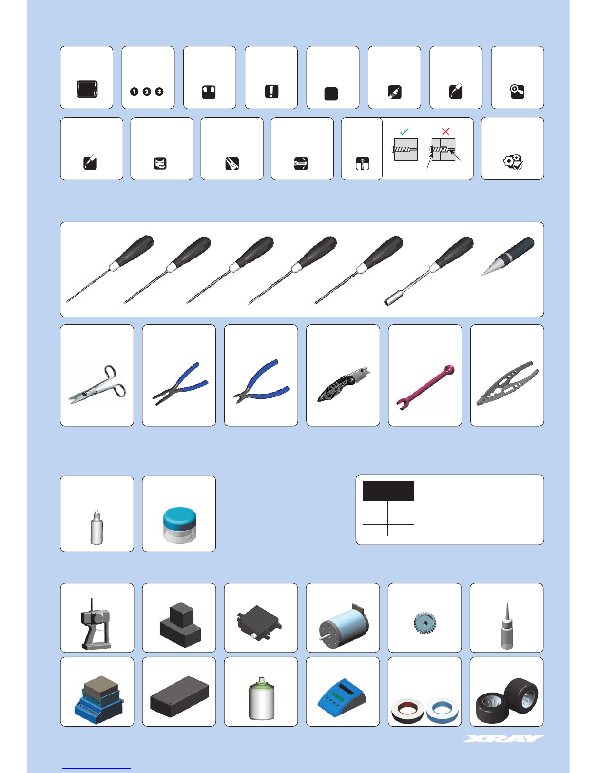
TOOLS REQUIRED
EQUIPMENT REQUIRED
EQUIPMENT INCLUDED
Apply oil Use pliers
HUDY Premium Silicone Oils
Oil 600cSt (#106360)
Oil 10 000cSt (#106510)
Side Cutters
(HUDY #189010)
Turnbuckle Wrench 4mm
(HUDY #181040)
Reamer
(HUDY #107600)
or
(HUDY #107601)
Combination Pliers
(HUDY #189020)
HUDY TOOLS:
05
Tighten screw
gently
Cut off remaining
material
Detail view
Apply grease Ensure smooth
non-binding movement
Diff Grease
(HUDY #106211)
Assembly view
Scissors
(HUDY #188990)
4.0 mm
SAMPLE OF
OPTIONAL PARTS
#37XXXX OPTION 1
#37XXXX OPTION 2
#37XXXX OPTION 3
DETAIL
Socket: 7.0mmPhillips: 3.0mmAllen: 1.5mm Allen: 2.0mm Allen: 3.0mmAllen: 2.5mm
Pocket Hobby Knife
(HUDY #188981)
RC Professional Multi Tool
(HUDY #183011)
Pinion Gear and set-screw
Transmitter Steering ServoReceiver Bearing Oil
(HUDY #106230)
Speed Controller
Electric Motor
Lexan™ Paint Battery Charger Wheels & Tires & Inserts
(HUDY #803070 & #803080)
LiPo Battery
Fibre Tape
(HUDY #107870)
Double-sided Tape
(HUDY #107875)
Page 5
5
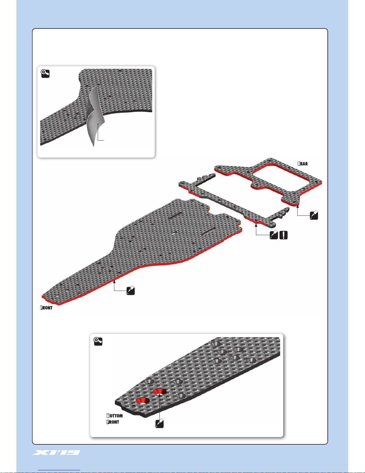
CHASSIS PREPARATION
To protect and seal edges of graphite parts, sand edges smooth and then apply CA glue.
Make it: this for chassis edges and countersunk holes.
Fine sandpaper
Use fine sandpaper to sand smooth
the edges of all graphite parts.
CA
CA
CA
CA
Apply only a bit of CA glue in the countersunk holes.
IMPORTANT
DETAIL
DETAIL
Page 6
6
303123-O
303123-O
303123-O
372213
902306
376232
960030
376364-O
372320
372117
376260-O
902306
903308
372320
372320
373241
902310
901303
303432-O
372492
371015
965019
373241
372290
962030
302652
372213
373242
372290
372321
902310
371064
371065
376361-O
903308
901308
970050
970050
970050
372133
373243
303454
333452
901303
902306
372410
930407
372281
372290
901304
375221
372177
965019
372213
902306
303123-O ALU SHIM 3x6x2.0mm - ORANGE (10)
302652 BALL END 4.9mm WITH THREAD 4mm (2)
303432-O ALU ANTI-ROLL BAR BUSHING - ORANGE (2)
303454 BALL JOINT 4.9mm - OPEN (4)
333452 ALU ANTI-ROLL BAR PIVOT BALL 4.9mm (2)
371015 CHASSIS - 2.5mm GRAPHITE - V3
371064 X1 ARM MOUNT PLATE - 2.5mm GRAPHITE
371065 X1’19 GRAPHITE ARM MOUNT PLATE - WIDE TRACK-WIDTH - 2.5mm
372117 X1’19 GRAPHITE LOWER SUSPENSION ARM 2.5mm
372133 X1 GRAPHITE UPPER SUSPENSION ARM 2.5mm
372177 FRONT COIL SPRING 3.6x6x0.5mm; C=3.5 - GOLD (2)
372213 X1 COMPOSITE STEERING BLOCK & BACKSTOPS
372281 X1 KING PIN (2)
372290 ALU SHIM 3.2x4.8x0.5 (4)
372320 X1 COMPOSITE ARM BUSHING (4)
372321 X1 COMPOSITE CASTER & CAMBER BUSHING (2+2+2+2)
372410 X1 ALU BALL-BEARING ANTI-ROLL BAR HOLDER - ORANGE
372492 ANTI-ROLL BAR - FRONT 1.2mm
373241 COMPOSITE PIVOTBALL UNIVERSAL 6.0mm (2)
373242 COMPOSITE PIVOTBALL UNIVERSAL 6.0mm - SHORT (2)
373243 BALL END 6.0mm WITH THREAD 4mm (2)
375221 X1 FRONT WHEEL AXLE - HUDY SPRING STEEL™ (2)
376232 X1’19 GRAPHITE TOP DECK 2.5mm
376260-O X1’18 ALU SERVO MOUNT - ORANGE
376361-O ALU MOUNT 26.5mm - ORANGE (2)
376364-O ALU MOUNT 10.8mm - ORANGE (2)
901303 HEX SCREW SB M3x3mm (10)
901304 HEX SCREW SB M3x4mm (10)
901308 HEX SCREW SB M3x8mm (10)
902306 HEX SCREW SH M3x6mm (10)
902310 HEX SCREW SH M3x10mm (10)
903308 HEX SCREW SFH M3x8mm (10)
930407 BALL-BEARING 4x7x2.5 STEEL SEALED - OIL (2)
960030 NUT M3 (10)
962030 WASHER S 3x6x0.3mm (10)
965019 E-CLIP 1.9 (10)
970050 O-RING 5x1mm (10)
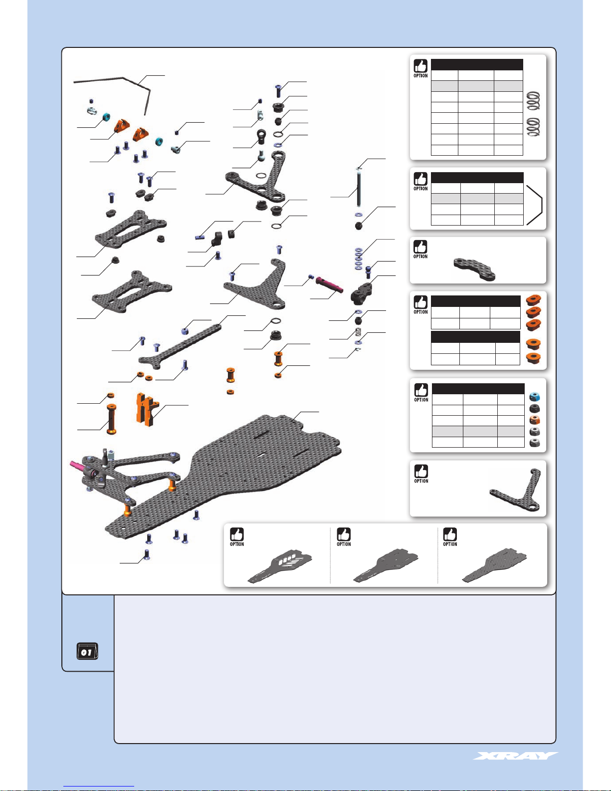
1. FRONT SUSPENSION
BAG
372321
FRONT COIL SPRINGS
#372176 C=1.5 GOLD OPTION
#372177 C=2.0 SILVER INCLUDED
#372178 C=2.5 BLACK OPTION
#372179 C=3.0 GREY OPTION
#372180 C=3.5 GOLD OPTION
#372181 C=4.0 SILVER OPTION
#372182 C=5.0 BLACK OPTION
#372183 C=5.5 GREY OPTION
ANTI-ROLL BARS
#372491 1.1mm OPTION
#372492 1.2mm INCLUDED
#372493 1.3mm OPTION
#372494 1.4mm OPTION
#371017
CHASSIS - 2.0mm ALU FLEX - V3
#371016
CHASSIS - 2.0mm ALU - V3
#371019
CHASSIS - 2.5mm GRAPHITE - HARD
ALU CAMBER BUSHINGS
#372325 1.5°, 2.0° (2) OPTION
#372326 1.0°, 2.5° (2) OPTION
ALU CASTER BUSHINGS
#372327 6°, 9° (3) OPTION
#372328 3°, 12° (3) OPTION
ALU NUTS M3
#296530-B ALU BLUE OPTION
#296530-K ALU BLACK OPTION
#296530-O ALU ORANGE OPTION
#960030 STEEL SILVER INCLUDED
#960031 ALU SILVER OPTION
#372087
X1 GRAPHITE FRONT ARM BRACE 2.5mm
#372115
X1 GRAPHITE LOWER
SUSPENSION ARM 2.5mm
Page 7
7
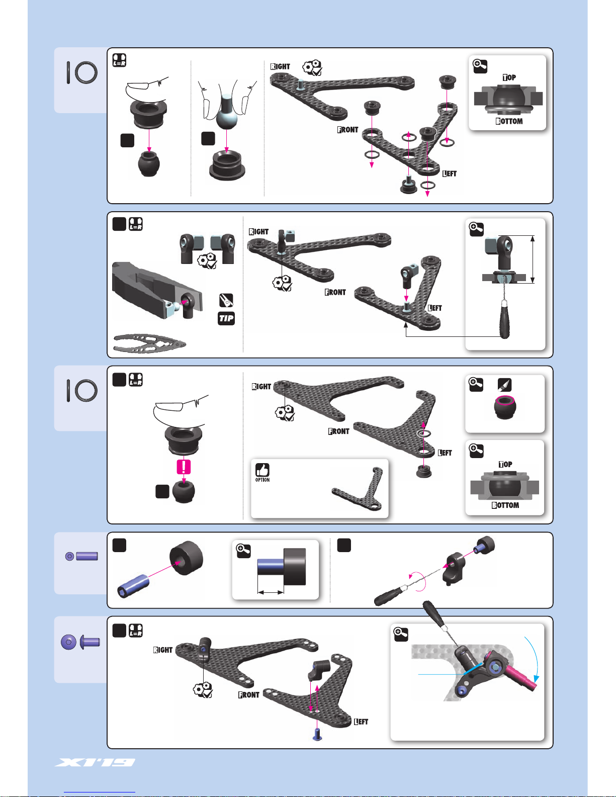
970050
O 5x1
970050
O 5x1
901308
SB M3x8
902306
SH M3x6
1.5 mm
UPPER ARMS
UPPER ARMS
LOWER ARMS
LOWER ARMS
2x
The adjustable backstops are used to limit the steering angle.
Adjust the backstop with the set- screw to achieve the maximum
steering angle needed. Adjust the steering angle on both L & R
sides to the same amount.
BACKSTOP
STEERING ANGLE
1.5 mm
DETAIL
INITIAL SETTING
2.0 mm
NOTE ORIENTATION
DETAIL
RC Professional Multi Tool
(HUDY #183011)
6x
2x
2x
2x
2x 2x
2x
1. FRONT SUSPENSION
5mm
COMPOSITE BALL
6.0mm
BALL END
SHORT COMPOSITE BALL
CUTAWAY VIEW
DETAIL
CUTAWAY VIEW
DETAIL
Remove excess material
DETAIL
19.5mm
DETAIL
#372115
X1 GRAPHITE LOWER
SUSPENSION ARM 2.5mm
To improve steering in low-traction
conditions with standard front F1 tires.
Page 8
8
1. FRONT SUSPENSION
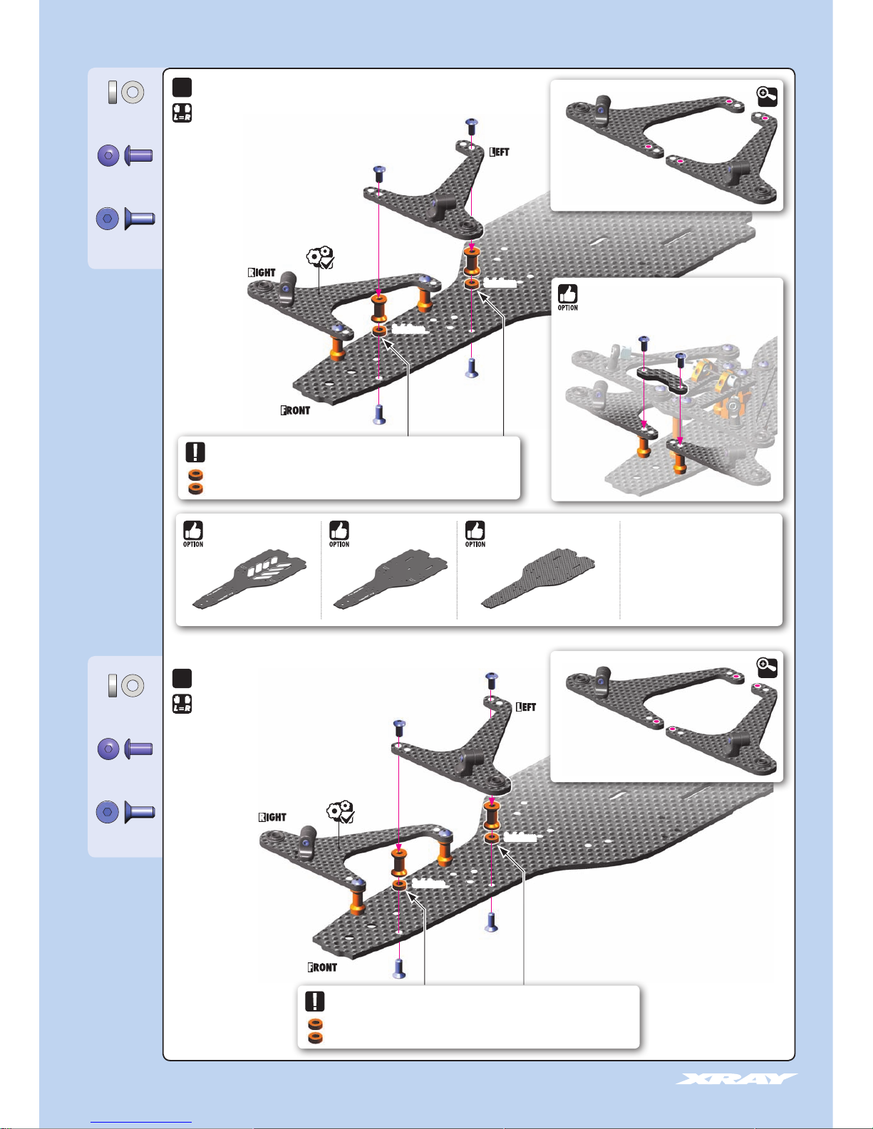
902306
SH M3x6
902306
SH M3x6
903308
SFH M3x8
903308
SFH M3x8
303123-O
SHIM 3x6x2
303123-O
SHIM 3x6x2
3x6x2mm
3x6x2mm
3x6x2mm
3x6x2mm
STANDARD TRACK-WIDTH
WIDE TRACK-WIDTH
(INITIAL SETTING)
ALTERNATIVE 1
ALTERNATIVE 2
These shims adjust the roll-center of the front bottom arm as well as the front ride height. The
thickness of the shim depends on the tire diameter. For initial setting, use the 3x6x2mm shim.
IMPORTANT!
Use the same shim thickness under all 4 posts.
These shims adjust the roll-center of the front bottom arm as well as the front ride height. The
thickness of the shim depends on the tire diameter. For initial setting, use the 3x6x2mm shim.
IMPORTANT!
Use the same shim thickness under all 4 posts.
Standard track-width setting is used for standard F1
front tires such HUDY, RIDE, HOT RACE.
To make sure that you use the correct setting,
measure the track-width with the tires; the trackwidth must be maximum 190mm.
Wide track-width setting is used for the narrow F1
front tires such as Volante.
To make sure that you use the correct setting,
measure the track-width with the tires; the trackwidth must be maximum 190mm.
#371017
CHASSIS - 2.0mm ALU FLEX - V3
#371016
CHASSIS - 2.0mm ALU - V3
#371019
CHASSIS - 2.5mm GRAPHITE - HARD
2.5mm CHASSIS HARD
For low-traction conditions, as it improves
overall traction.
ALU CHASSIS
Makes the car easier to drive and more stable
in high-traction conditions or with tires that
generate oversteering problems.
#372087
X1 GRAPHITE FRONT ARM BRACE 2.5mm
3x8mm
The brace makes the car easier to drive. Recommended for
high-traction conditions.
2x
2x
DETAIL
DETAIL
INITIAL SETTING
Page 9
9
1. FRONT SUSPENSION
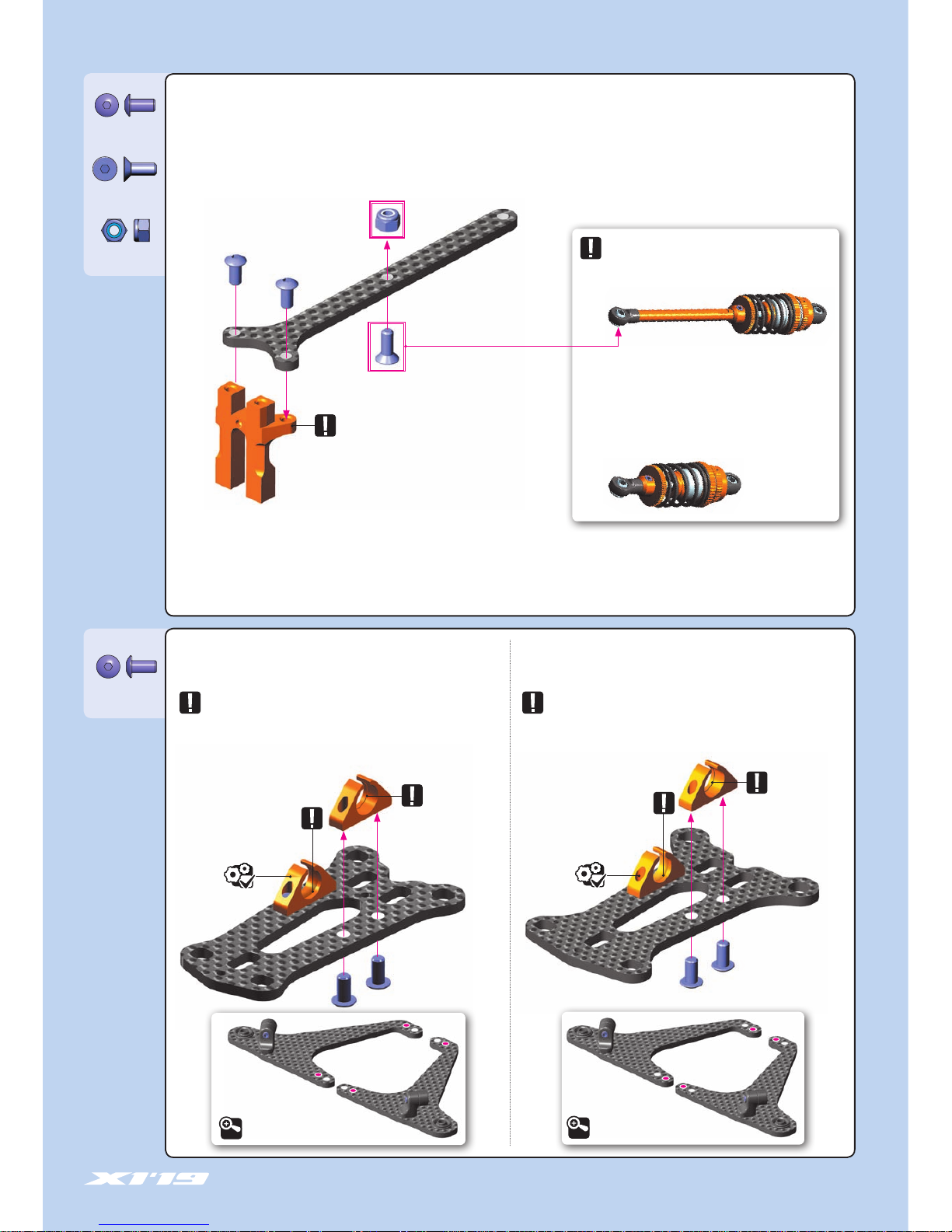
903308
SFH M3x8
960030
N M3
STANDARD TRACK-WIDTH WIDE TRACK-WIDTH
(INITIAL SETTING)
ALTERNATIVE 1 ALTERNATIVE 2
NOTE ORIENTATION
NOTE ORIENTATION
NOTE ORIENTATION
NOTE ORIENTATION
NOTE ORIENTATION
IMPORTANT!
Use this wide track-width arm mount plate only with combination
with wide track-width setting of the graphite lower suspension
arm.
IMPORTANT!
Use this standard track-width arm mount plate only with combination with standard track-width setting of the graphite lower
suspension arm.
902306
SH M3x6
902306
SH M3x6
ALTERNATIVE 1
LONG SHOCK (FORWARD MOUNT POSITION)
For the LONG shock alternative, mount the shock
holder on the top deck.
ALTERNATIVE 2
SHORT SHOCK (REARWARD MOUNT POSITION)
For the SHORT shock alternative, without the adaptor,
mount the shock holder on the graphite plate for
mounts (page 17/ step 2)
DETAIL
DETAIL
Page 10

10
1. FRONT SUSPENSION
962030
S 3x6x0.3
902310
SH M3x10
All four bushings MUST have same orientation.
These bushings adjust the front CAMBER:
These eccentric bushings adjust the front CAMBER.
The more camber angle, the more steering there is. However, it makes the car
more sensitive and more difficult to drive.
Use LESS camber angle for carpet and other high-traction tracks.
Use MORE camber on asphalt and low-traction tracks.
IMPORTANT!
= 1.0° CAMBER
= 1.5° CAMBER
= 2.0° CAMBER
= 2.5° CAMBER
ECCENTRIC
BUSHINGS
ECCENTRIC
BUSHINGS
DETAIL
3x6x0.3mm
3x6x0.3mm
902310
SH M3x10
903308
SFH M3x8
303123-O
SHIM 3x6x2
DETAIL
ECCENTRIC
BUSHINGS
3x6x2mm
3x6x2mm
STANDARD TRACK-WIDTH
WIDE TRACK-WIDTH
(INITIAL SETTING)
ALTERNATIVE 1
ALTERNATIVE 2
FREE
MOVEMENT
INITIAL SETTING
NOTE
ORIENTATION
All three bushings MUST have same orientation.
These bushings adjust the front CASTER:
These eccentric bushings adjust the front CASTER.
MORE caster angle = better cornering speed, increased traction rolling.
Use on large, open tracks where cornering speed is needed.
LESS caster angle = more reactive steering. Use on technical tracks where
a lot of steering response is needed.
IMPORTANT!
= 3° CASTER
= 6° CASTER
= 9° CASTER
= 12° CASTER
INITIAL SETTING
ALU CAMBER BUSHINGS
#372325 CAMBER 1.5°, 2.0° (2) ALU OPTION
#372326 CAMBER 1.0°, 2.5° (2) ALU OPTION
ALU CASTER BUSHINGS
#372327 CASTER 6°, 9° (3) ALU OPTION
#372328 CASTER 3°, 12° (3) ALU OPTION
Page 11
11
1. FRONT SUSPENSION
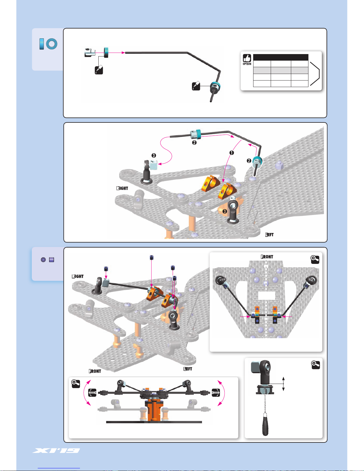
When the anti-roll bar is set, verify that both sides move at the same time.
If they do, the bar is set up correctly. If not, adjust the wire so that it is flat.
DETAIL
DETAIL
Set the bar into the center, remove the play in the bushings, and
tighten the set-screws fully.
CENTER
DETAIL
If the sides still does
not move at the same
time, adjust the length
of the bar holders.
2.0 mm
901303
SB M3x3
930407
BB 4x7x2.5
OIL
OIL
BEARING OIL
(HUDY #106230)
BEARING OIL
(HUDY #106230)
ANTI-ROLL BARS
#372491 1.1mm OPTION
#372492 1.2mm INCLUDED
#372493 1.3mm OPTION
#372494 1.4mm OPTION
Page 12

12
1. FRONT SUSPENSION
901304
SB M3x4
372290
SHIM 3.2x4.8x0.5
965019
C 1.9
After assembling the steering block, do the following:
1. Loosen the set-screw slightly.
2. Use your thumb to press down on the top of the kingpin, while
using your other fingers to pull up the steering block.
3. Tighten the set-screw.
1.5 mm
TIGHTEN GENTLY
The number of the shims affects
the front ride height. Determine
the proper amount of shimming
based on tire diameter.
LOW traction & bumpy track:
10K cSt (#106510 HUDY)
HIGH traction & flat track:
30K cSt (#106530 HUDY)
FREE MOVEMENT
RECOMMENDED
HUDY SILICONE OIL
3.2x4.8x0.5mm (5x)
3.2x4.8x0.5mm (2x)
3.2x4.8x0.5mm (1x)
3.2x4.8x0.5mm (1x)
4mm THREAD
OIL
1 - easier to drive
2 - improved steering response
3 - improved overall steering
POSITION 3.
There are THREE Ackermann positions on the steering block:
DETAIL
INITIAL SETTING
2x
2x
2x
3
3
3
3x6x1mm
2
1
If using less bumpsteer shims on the steering plate
and the steering linkage is touching the steering
block, use 3x6x1mm composite shim (bag 5).
FRONT COIL SPRINGS
#372176 C=1.5 GOLD OPTION
#372177 C=2.0 SILVER INCLUDED
#372178 C=2.5 BLACK OPTION
#372179 C=3.0 GREY OPTION
#372180 C=3.5 GOLD OPTION
#372181 C=4.0 SILVER OPTION
#372182 C=5.0 BLACK OPTION
#372183 C=5.5 GREY OPTION
Page 13

13
#371148
X1 ALU 2.0mm REAR POD LOWER PLATE
#371149
X1 GRAPHITE 2.0mm REAR POD LOWER PLATE
371320
371320
371320
981210
902306
903312
902306
903306
371096
371078
902306
902306
902305
373548
372650
378153
378141
378141
372662
372650
373036
371147
903306
902306
902306
902305
373121-O
373121-O
902258
903310
373094
960030
373585
903306
373073-O
960030
960030
960030
373015
373025
903305
903305
371182
371182
903308
378153
372650
981210
372662
303241
303241
371190
373066
373094
373591
902308
960030
306219
903306
376361-O
901308
2. REAR SUSPENSION
BAG
02
303241 PIVOT BALL UNIVERSAL 5.8 WITH HEX (4)
306219 COMPOSITE SET OF SERVO SHIMS (4)
371078 X1’19 GRAPHITE REAR BRACE 2.5mm
371096 X1’19 GRAPHITE PLATE FOR MOUNTS 2.5mm
371147 X1 GRAPHITE 2.5mm REAR POD LOWER PLATE
371182 X1 GRAPHITE POD LINK PLATE 2.5mm (2)
371190 COMPOSITE POD LINK (2)
371320 COMPOSITE BODY POST (2)
372650 BALL-END 4.2mm - THREADED - HUDY SPRING STEEL™ (2)
372662 COMPOSITE BALL-JOINT 4.2 mm (4)
373015 X1’19 ALU REAR BULKHEAD - MOTOR (RIGHT)
373025 X1’19 ALU REAR BULKHEAD - LEFT
373036 X1’19 GRAPHITE REAR WING MOUNT 2.5mm
373066 ALU PIVOT BALL
373073-O ALU REAR BRACE MOUNT 13mm - ORANGE (2)
373087 GRAPHITE BATTERY BACKSTOP 2.0mm
373094 LOWER & UPPER PIVOT BRACE - LOW ROLL-CENTER - HARD - V3
373121-O ALU STAND M3 6x6.4mm - ORANGE (4)
373548 X1 REAR POD UPPER PLATE - 2.5mm GRAPHITE
373585 SIDE SPRING C=0.9 - GOLD (2)
373591 COMPOSITE SIDE SPRING HOLDER (2)
376361-O ALU MOUNT 26.5mm - ORANGE (2)
378141 X1 SIDE LINKAGE TUBE (2)
378153 COMPOSITE LINKAGE SHAFT (2)
901308 HEX SCREW SB M3x8 (10)
902258 HEX SCREW SH M2.5x8 (10)
902305 HEX SCREW SH M3x5 (10)
902306 HEX SCREW SH M3x6 (10)
902308 HEX SCREW SH M3x8 (10)
903305 HEX SCREW SFH M3x5 (10)
903306 HEX SCREW SFH M3x6 (10)
903308 HEX SCREW SFH M3x8 (10)
903310 HEX SCREW SFH M3x10 (10)
903312 HEX SCREW SFH M3x12 (10)
960030 NUT M3 (10)
981210 PIN 2x10 (10)
902305
902306
373087
SIDE SPRINGS
#373584 C=0.6 SILVER OPTION
#373585 C=0.9 GOLD INCLUDED
#373586 C=1.2 BLACK OPTION
#373587 C=1.5 SILVER OPTION
#373588 C=1.8 GOLD OPTION
#301351-O
ALU ADJUSTABLE BODY POST STOP (2)
ALU NUTS M3
#296530-B ALU BLUE OPTION
#296530-K ALU BLACK OPTION
#296530-O ALU ORANGE OPTION
#960030 STEEL SILVER INCLUDED
#960031 ALU SILVER OPTION
Page 14

14
2. FRONT SUSPENSION
902306
SH M3x6
903306
SFH M3x6
NOTE
ORIENTATION
Ensure free, smooth movement without
excessive freeplay.
Gently scuff the bottom of the composite lower
pivot brace on sandpaper to make the surface
slightly rough. This will help the lower pivot
brace to grip the chassis surface better.
DETAIL
Sandpaper
Sandpaper
#371148
X1 ALU 2.0mm REAR POD LOWER PLATE
#371149
X1 GRAPHITE 2.0mm REAR POD LOWER PLATE
NOTE ORIENTATION
NOTE ORIENTATION
DO NOT TIGHTEN FULLY
902306
SH M3x6
960030
N M3
903310
SFH M3x10
903306
SFH M3x6
GRAPHITE PLATE is lighter weight, makes the car rotate faster.
ALUMINUM PLATE is heavier weight, makes the car more stable
and easier to drive.
ALU NUTS M3
#296530-B ALU BLUE OPTION
#296530-K ALU BLACK OPTION
#296530-O ALU ORANGE OPTION
#960030 STEEL SILVER INCLUDED
#960031 ALU SILVER OPTION
Page 15

15
902258
SH M2.5x8
Do not tighten fully,
pivotballs must turn freely.
Do not tighten fully,
pivotballs must turn freely.
902305
SH M3x5
902306
SH M3x6
• OUTER POSITION
(INITIAL SETTING)
Straight link.
Easier to drive.
• INNER POSITION
Angled link.
Increased in- corner steering.
(INITIAL SETTING)
Ensure free, smooth
movement. If the pod
plate does not move
freely, loosen the nuts
of composite pivot brace
and tighten again.
DETAIL
POD LINKAGE POSITION
DETAIL
903306
SFH M3x6
2x
2x
903305
SFH M3x5
TIGHTEN FULLY
NOTE ORIENTATION
NOTE
ORIENTATION
NOTE
ORIENTATION
2. REAR SUSPENSION
Page 16

16
902306
SH M3x6
902306
SH M3x6
903306
SFH M3x6
901308
SB M3x8
NOTE ORIENTATION
NOTE ORIENTATION
"CLICK"
2.0mm
Make sure both side springs are tightened equally, to avoid
unwanted tweak.
DETAIL
NOTE ORIENTATION
DETAIL
CA
DETAIL
SOFTER SPRINGS:
Makes the car easier to drive on
low-traction tracks but more difficult to drive on
high-traction tracks.
HARDER SPRINGS:
Improves steering response, but also increases
traction rolling.
960030
N M3
NOTE ORIENTATION
For battery backstop adjustment check
page 34 / step 1.
INITIAL SETTING
2. REAR SUSPENSION
IMPORTANT
SIDE SPRINGS
#373584 C=0.6 - SILVER OPTION
#373585 C=0.9 - GOLD INCLUDED
#373586 C=1.2 - BLACK OPTION
#373587 C=1.5 - SILVER OPTION
#373588 C=1.8 - GOLD OPTION
Page 17

17
902306
SH M3x6
902306
SH M3x6
903308
SFH M3x8
3x6x3mm
NOTE ORIENTATION
903312
SFH M3x12
902308
SH M3x8
981210
P 2x10
#301351-O
ALU ADJUSTABLE BODY POST STOP (2)
Very handy, easily externally-adjustable body
post made from Swiss 7075 T6 aluminum. Allows
for adjustment of body height by 3mm without
needing to change the position on the body post.
960030
N M3
960030
N M3
960030
N M3
Thread lock
306219
SHIM 3x6x3
3x6mm
3x12mm
903306
SFH M3x6
6mm THREAD
NOTE ORIENTATION
2. REAR SUSPENSION
From
BAG
ALTERNATIVE 2
SHORT SHOCK (REARWARD MOUNT POSITION)
For the SHORT shock alternative, without the adaptor, mount
the shock holder on the graphite plate for body mounts.
ALU NUTS M3
#296530-B ALU BLUE OPTION
#296530-K ALU BLACK OPTION
#296530-O ALU ORANGE OPTION
#960030 STEEL SILVER INCLUDED
#960031 ALU SILVER OPTION
Page 18

18
The angle of the side tubes has a fine effect on car performance.
The angle is adjusted with shims between the pivot ball and the rear
brace and/or upper plate.
The HIGHER the angle, the stiffer it feels and the less it rolls.
The LESS (flatter) the angle, the softer it feels and the more it rolls.
OPTIONAL SIDE SHOCK
#378100 - Optional side shock can be used to improve
traction in low- and medium-traction conditions.
The optional side shock REPLACES the 2 side tubes.
#362650
#378100 OPTIONAL SIDE SHOCK
#372651
3x6x2mm
3x8mm
3x6mm
3x6mm
HUDY OILS
#106510 10 000cSt INCLUDED
#106515 15 000cSt OPTION
#106520 20 000cSt OPTION
#106530 30 000cSt OPTION
#106540 40 000cSt OPTION
#106550 50 000cSt OPTION
2x 2x
Add oil in each slot of the COMPOSITE side shock tubes.
NOTE:
Add oil only in the slots, not on the whole tube.
After assembling the side tubes, check for smooth operation.
It is very important to re-oil the side tubes, at least once per race day.
You may use different oil thicknesses depending on track conditions.
OIL
For HIGH grip use SOFTER oils
For LOW grip or ASPHALT use HARDER oils
SIDE SHOCK - OPTIONAL PARTS (NOT INCLUDED)
#378100 Side Shock Absorber - SET
#362650 Ball End 4.9mm with Thread 6mm (2)
#303123-O Alu Shim 3x6x2.0mm - Orange (10)
#372651 Ball Universal 4.9mm - HUDY Spring Steel™ (2)
#902308 Hex Screw SH M3x8 (10)
3x6x2mm
REMOVE Graphite Battery Backstop
NOTE
2. REAR SUSPENSION
Page 19

19
BAG
03
#375014
GRAPHITE REAR GEAR DIFF AXLE SHAFT
GEAR DIFF - SPUR GEARS
#375776 76T / 64P OPTION
#375780 80T / 64P OPTION
#375784 84T / 64P OPTION
#375788 88T / 64P OPTION
#375792 92T / 64P OPTION
#374901 XRAY GEAR
DIFFERENTIAL 1/10
FORMULA - SET
#374901
Included in set
#373042
ALU UPPER ECCENTRIC CLAMP
#930238
CERAMIC AXIAL THRUSTBEARING
F3-8 3x8x3.5mm
#930230
CERAMIC BALL 3.175mm (12)
9g lighter for great weight savings and improved
acceleration, but more fragile.
#375010
GRAPHITE REAR AXLE SHAFT
3. BALL DIFFERENTIAL
303142-O ALU SHIM 3x5x0.5mm - ORANGE (10)
303143 ALU SHIM 3x5x0.25mm (10)
372072 COMPOSITE BALL-BEARING HUB (2)
373041 ALU UPPER CLAMP FOR BALL-BEARING
375012 STEEL REAR AXLE SHAFT - HUDY SPRING STEEL™
375026 X1 ALU REAR DRIVE AXLE - RIGHT
375036 X1 ALU REAR WHEEL HUB - RIGHT
375046 X1 ALU REAR WHEEL HUB - LEFT
375050-O ALU DIFF HUB - ORANGE
375080 D-LOCK DIFF PLATE (2)
375090-O SET OF ALU SHIMS 6.37x8.4mm (0.5mm, 1.0mm, 2.0mm) - ORANGE
375896 COMPOSITE SPUR GEAR - 96T / 64P
375390 ALU 7075 HEX SCREW M3x8 (6)
901304 HEX SCREW SB M3x4 (10)
908258 HEX SCREW SOCKET HEAD CAP M2.5x8 (10)
930130 CARBIDE BALL 3.175mm (12)
930138 CARBIDE BALL-BEARING AXIAL F3-8 3x8x3.5 - V2
941438 BALL-BEARING 1/4”x3/8”x1/8” RUBBER SEALED - OIL (2)
951438 BALL-BEARING 1/4” x 3/8” x 1/8” FLANGED - STEEL SEALED - OIL (2)
960030 NUT M3 (10)
963030 CONE WASHER ST 3x8x0.5 (10)
981214 PIN 2x14 (10)
901304
375026
960030
930138
941438
941438
930130
941438
375012
375090-O
375090-O
372072
375390
373041
375050-O
981214
375036
375080
375080
951438
372072
951438
908258
375046
375896
963030
375390
373041
303142-O
303143
ALU NUTS M3
#296530-B ALU BLUE OPTION
#296530-K ALU BLACK OPTION
#296530-O ALU ORANGE OPTION
#960030 STEEL SILVER INCLUDED
#960031 ALU SILVER OPTION
BALL DIFF - SPUR GEARS
#375872 72T / 64P OPTION
#375875 75T / 64P OPTION
#375876 76T / 64P OPTION
#375878 78T / 64P OPTION
#375880 80T / 64P OPTION
#375896 96T / 64P INCLUDED
Page 20

20
DETAIL
The axle must have a VERY small amount
of side play. If there is no side play, the axle
may bind and damage the ball-bearings.
IMPORTANT
#374901
XRAY GEAR DIFFERENTIAL 1/10 FORMULA - SET
#375014
GRAPHITE REAR GEAR DIFF AXLE SHAFT
9g lighter for great weight savings and improved
acceleration, but more fragile.
#375010
GRAPHITE REAR AXLE SHAFT
NOTE
ORIENTATION
3. BALL DIFFERENTIAL
3x5x0.5mm
The thickness of these shims affects rear ride height, so determine the proper amount
of shimming based on tire diameter.
IMPORTANT: Always use the same thickness of shims on both left & right sides.
For INITIAL SETTING, use (2x) 3x5x0.5mm on both left & right sides.
Optionally included: (4x) 3x5x0.25mm shims for fine tuning.
A SHORTER car rotates harder in slow
corners and has improved forward traction.
A LONGER car is more free in high-speed
corners and will feel more linear, especially
during fast direction changes.
375390
ALU SCH M3x8
303142-O
SHIM 3x5x0.5
303143
SHIM 3x5x0.25
#373042
ALU UPPER ECCENTRIC CLAMP
Wheelbase adjustment
Rearward position
Standard position
(+1mm)
(0mm)
Frontward position
(-1mm)
+
951438
BB 1/4“x3/8“x1/8“
375090-O
6.4x8.4x1.0
375090-O
6.4x8.4x2.0
375090-O
6.4x8.4x0.5
908258
SCH M2.5x8
Use additional shims to widen the rear track-width. Use the same shims
on both sides. For initial assembly use 6.4x8.4x1mm shims.
OIL
OIL
Flanged
Flanged
Bearing Oil
(HUDY #106230)
Bearing Oil
(HUDY #106230)
Page 21

21
DIFF GREASE
(HUDY #106211)
8.0mm 7.8mm
3.0mm
3.2mm
930138
BA 3x8
941438
BB 1/4“x3/8“x1/8“
930130
B 3.1
963030
ST 3x8
901304
SB M3x4
981214
P 2x14
#930238
CERAMIC AXIAL THRUSTBEARING
F3-8 3X8X3.5
#930230
CERAMIC BALL 3.175mm (12)
This nut affects the tightness and stiffness of the rear differential.
Tighten the nut gently so the diff does not slip under power, but do
not overtighten or the diff balls and/or plates may be damaged.
DIFF
GREASE
BEARING OIL
(HUDY #106230)
OIL
OIL
NOTE
ORIENTATION
Thread the set-screw
deep enough into the
wheel adaptor so it does
not protrude.
Tighten fully.
NOTE
ORIENTATION
NOTE
ORIENTATION
NOTE
ORIENTATION
NOTE
ORIENTATION
DIFF GREASE
(HUDY #106211)
960030
N M3
3. BALL DIFFERENTIAL
1.5 mm
DETAIL STEP
CUTAWAY VIEW
DETAIL
DETAIL
Page 22

22
#308039
ALU PROGRESSIVE SHOCK SYSTEM - SET (2)
Progressive shock system for improved traction and steering
characteristics. Shock insert has 3 triangle cuts and is used with
piston WITHOUT holes. The hardness of the shock is influenced
not by the holes in the piston, but rather by the insert.
4. CENTER SHOCK
BAG
04
1.1mm
1.2mm
1.3mm
1.1mm
1.2mm
1.3mm
308333
303241
308353-O
308082
965023
965023
308037
308323
970130
972030
378062
308037
308327-O
308316
901303
308274
378072-O
308042-O
378073-O
303241
308092
SHOCK PISTONS
303241 BALL UNIVERSAL 5.8mm HEX (4)
308037 COMPOSITE PISTONS 4-HOLE 1.0-1.2mm, 3-HOLE 1.0-1.2mm
308042-O ALU SHOCK ADJUSTABLE NUT - ORANGE (2)
308082 SHOCK ABSORBER MEMBRANE (4)
308092 SHOCK FOAM INSERTS (4)
308316 SHOCK BALL JOINT - OPEN (4)
308323 ALU XRAY SHOCK BODY (2)
308327-O ALU CAP FOR XRAY SHOCK BODY - ORANGE
308333 COMPOSITE SHOCK PARTS FOR ALU SHOCKS
308353-O ALU SHOCK CAP-NUT WITH VENT HOLE - ORANGE (2)
308274 XRAY SPRING-SET C=2.3
378062 X1 SHOCK SHAFT
378072-O X1 ALU SHOCK SPRING COLLAR - ORANGE
378073-O X1’18 ALU SHOCK ADAPTER - ORANGE
901303 HEX SCREW SB M3x3 (10)
965023 E-CLIP 2.3 (10)
970130 O-RING 13 x 1.5 (10)
972030 SILICONE O-RING 3 x 2 (10)
XRAY SPRINGS
#308263 C = 2.3-2.6 (2) OPTION
#308264 C = 2.5-2.8 (2) OPTION
#308274 C = 2.3 (2) INCLUDED
#308275 C = 2.5 (2) OPTION
#308286 C = 2.6 (2) OPTION
#308276 C = 2.7 (2) OPTION
#308288 C = 2.8 (2) OPTION
#308277 C = 2.9 (2) OPTION
#308290 C = 3.0 (2) OPTION
Page 23

23
970130
O 13x1.5
972030
O 3x2
SHOCK OIL
SHOCK OIL
965023
C 2.3
DETAIL
4. CENTER SHOCK
SHOCK OIL
NOTE
ORIENTATION
DETAIL
CUTAWAY VIEW
Be careful not to cross-thread the
collar on the shock body.
DETAIL
1.1mm
1.2mm
1.3mm
1.1mm
1.2mm
1.3mm
3 HOLES
4 HOLES
INITIAL SETTING
SHOCK PISTON ADJUSTMENT
Page 24

24
When installing the shock cap assembly on the shock
body, some oil will leak out... this is normal.
Tighten the cap and clean off any excess oil.
After the shock is assembled, the shock rod will push
itself out of the shock body fairly quickly.
Follow the next procedure to adjust the rebound.
➊
➋
➌
➍
After you insert the membrane, ensure
that it is fully seated inside the alu cap.
Foam insert
CUTAWAY VIEW
OIL 600cSt
Fully extend the piston rod so the piston is at the bottom of the shock body.
Hold the shock upright and slightly overfill the shock body with shock oil.
Let the oil settle and allow air bubbles to rise to the top. Slowly move the piston up and down to allow oil into all cavities within the shock body.
Extend the piston rod most of the way out of the shock body. Let the shock rest for 5 minutes to allow the air bubbles to escape.
Add shock oil as necessary.
➊
➋
➌
➍
➎
SHOCK FILLING
HUDY SHOCK OILS
#106310 100cSt
#106315 150cSt
#106320 200cSt
#106325 250cSt
#106330 300cSt
#106335 350cSt
#106340 400cSt
#106345 450cSt
#106350 500cSt
#106355 550cSt
#106360 600cSt
#106365 650cSt
#106370 700cSt
#106375 750cSt
#106380 800cSt
#106390 900cSt
#106410 1000cSt
#106420 2000cSt
SOFTER OIL
Recommended for bumpy
and low-traction tracks,
generates more traction.
HARDER OIL
Recommend for flat and
high-traction tracks, improves
steering response.
4. CENTER SHOCK
INITIAL SETTING
DETAIL
Page 25

25
RELEASE 2-3 turns TIGHTEN FULLY
➊ ➋ ➌
AFTER THE SHOCK IS ASSEMBLED YOU HAVE TO SET THE SHOCK REBOUND:
➊ Release the shock cap by 2-3 turns.
➋
Push the shock shaft fully up. For the first time the extra oil will release through
the hole in the alu cap-nut.
➌ Tighten the shock cup. When tightening the shock cap, extra oil will again release
through the hole in the alu cap - nut. When tightening, the shock shaft will push
out from the shock body.
REBOUND CHECK:
It is very important to push the shock shaft into the shock body slowly otherwise air can come
into the shock body which would create bubles.
100% rebound - do not do step 2 and 3
75% rebound - repeat steps 1 to 3 until the shock shaft will push out 75% of its length
50% rebound - repeat steps 1 to 3 until the shock shaft will push out 50% of its length
25% rebound - repeat steps 1 to 3 until the shock shaft will push out 25% of its length
0% rebound - repeat steps 1 to 3 until the shock shaft will push out 0% of its length
If the shock shaft does not rebound enough, you will have to refill the shock with shock oil, and
then repeat the bleeding and rebound adjustment procedure.
901303
SB M3x3
An innovative new feature is to change the center shock length (and front mounting position). By using longer or shorter shock, the damping and steering can be changed.
REBOUND ADJUSTMENT REBOUND CHECK
0%
50%
75%
100%
25%
CHECK
4. CENTER SHOCK
Shock is built WITH adaptor.
Front mount is on graphite servo holder.
Improved driveability over bumps, improves on-power traction.
ALTERNATIVE 1 - LONG SHOCK
Shock is built WITHOUT adaptor.
Front mount is on graphite plate for mounts.
Improved steering response, quicker direction changes.
ALTERNATIVE 2 - SHORT SHOCK
CUTAWAY VIEW
DETAIL
Page 26

26
NOTE ORIENTATION
NOTE ORIENTATION
(Shiny finish side)
NOTE ORIENTATION
(Shiny finish side)
NOTE ORIENTATION
DOWNSTOP ADJUSTMENT
DETAIL DETAIL
Install the balls with Professional Multi
Tool (HUDY #183011)
The length of the shock absorber affects the amount of
rear downstop. To adjust, thread the ball-joint on or off the
bottom spring cap.
63mm
113mm
4. CENTER SHOCK
ALTERNATIVE 2 - LONG SHOCKALTERNATIVE 1 - SHORT SHOCK
Page 27

27
5. FINAL ASSEMBLY
BAG
302612-O ALU ADJ. TURNBUCKLE M3 L/R 39 mm - ORANGE - SWISS 7075 T6 (2)
302663 COMPOSITE BALL JOINT 4.9mm - OPEN - V2 (8)
302665 COMPOSITE BALL JOINT 4.9mm - CLOSED WITH HOLE (4)
303127-K ALU SHIM 3x6x4.0mm - BLACK (10)
306200-O ALU SERVO MOUNT - ORANGE (2)
306219 COMPOSITE SET OF SERVO SHIMS (4)
306301 ANTENNA MOUNT - THIN
306310 ANTENNA (2)
309400 BODY CLIP (8)
338586 SHIM 5x7x0.5 (10)
362650 BALL END 4.9mm WITH THREAD 6mm (2)
362651 BALL END 4.9mm WITH THREAD 8mm (2)
371201 X1 COMPOSITE FRONT BUMPER
371250 X1 LEXAN FRONT SPOILER (2)
371320 COMPOSITE BODY POST (2)
372503 COMPOSITE SERVO SAVER - X-STIFF - SET - V2
372540 X1 COMPOSITE STEERING ARM
372550-O X1 ALU STEERING PIVOT SHAFT
373512-K X1 COMPOSITE ADJUSTABLE REAR WING - BLACK
376130 COMPOSITE LiPo BATTERY BACKSTOP (2)
376364-O ALU MOUNT 10.8mm - ORANGE (2)
379701 XRAY X1 1/10 FORMULA BODY
203063 O-RING FOR 1/8 ON-ROAD SET-UP WHEEL (4)
902205 HEX SCREW SH M2x5 (10)
902306 HEX SCREW SH M3x6 (10)
902308 HEX SCREW SH M3x8 (10)
902310 HEX SCREW SH M3x10 (10)
903306 HEX SCREW SFH M3x6 (10)
903308 HEX SCREW SFH M3x8 (10)
903412 HEX SCREW SFH M4x12 (10)
906206 SCREW PHILLIPS FH 2.2x6 (10)
940508 BALL-BEARING 5x8x2.5 RUBBER SEALED - OIL (2)
940510 BALL-BEARING 5x10x4 RUBBER SEALED - OIL (2)
960040 NUT M4 (10)
981210 PIN 2x10 (10)
302665
306310
306301
903308
306200-O
Steering Servo
(NOT INCLUDED)
902308
372503
372503
362650
940508
372550-O
309400
309400
371320
371320
903306
305968~306000
(NOT INCLUDED)
Receiver
(NOT INCLUDED)
373512-K
376364-O
960040
371250
379701
940510
903412
902205
960040
376130
902310
902306
903306
362651
302663
302612-O
940508
372540
981210
306219
902310
303127-K
362650
906206
372503
902306
306219
Speed Controller
(NOT INCLUDED)
LiPo Battery
(NOT INCLUDED)
Rear Wheels & Tires
(#803080 OPTION)
Front Wheels & Tires
(#803070 OPTION)
Motor
(NOT INCLUDED)
From Servo
(NOT INCLUDED)
371201
903306
940510
203063
960040
902308
302612-O
302665
338586
#305968~306000 PINION GEAR HARDCOATED 18~50T/64P
#372541 ALU ADJUSTABLE SERVO SAVER SET
#371202 X1 COMPOSITE ADJUSTABLE FRONT AERO WING - ETS APPROVED
#371203-K X1 COMPOSITE ADJUSTABLE FRONT WING - BLACK - ETS APPROVED
#371203 X1 COMPOSITE ADJUSTABLE FRONT WING - WHITE - ETS APPROVED
#371290 X1 ALU BODY POST PLATE
#373511-K X1 COMPOSITE REAR WING - BLACK
#373513-K X1 COMPOSITE ADJUSTABLE REAR WING - BLACK - ETS APPROVED
#379702 XRAY X1 1/10 FORMULA BODY – WORLD CHAMPION EDITION
#803070 HUDY 1/10 FORMULA RUBBER TIRE - FRONT (2)
#803080 HUDY 1/10 FORMULA RUBBER TIRE - REAR (2)
Page 28

28
303127-K
SHIM 3x6x4
902306
SH M3x6
940508
BB 5x8x2.5
These shims adjust the bumpsteer.
When thicker shims are used here, incorner steering increases, but the car
becomes more difficult to drive.
There are two Ackermann positions on the steering arm.
INNER position: More Ackermann, makes the car easier to
drive, improves cornering speed (INITIAL SETTING).
OUTER position: Less Ackermann, makes the car more
responsive, improves in-corner steering.
903306
SFH M3x6
8mm THREAD
6mm THREAD
NOTE ORIENTATION
DETAIL
902308
SH M3x8
NOTE
ORIENTATION
3x6x4mm
5. FINAL ASSEMBLY
OIL
OIL
The steering arm has two positions for servo linkage mounting.
Always use this position
BEARING OIL
(HUDY #106230)
BEARING OIL
(HUDY #106230)
#372541 ALU ADJUSTABLE SERVO SAVER SET
INITIAL
SETTING
INITIAL
SETTING
DETAIL
Page 29

29
6mm THREAD
903306
SFH M3x6
NOTE ORIENTATION
5. FINAL ASSEMBLY
INITIAL SETTING
DETAIL
FROM SERVO
H = Hitec
F = Futaba
K = KO, JR, Airtronics, Sanwa
57.5 mm 57.5 mm
2x
STEERING LINKS
LEFT THREAD LEFT THREAD RIGHT THREADRIGHT THREAD
4x
LEFT THREAD
RIGHT THREAD
HUDY ALU SERVO HORNS
#293501 KO, Sanwa - 23T
#293502 Hitec - 24T
#293503 Futaba - 25T
HUDY CLAMP ALU SERVO HORNS
#293407 KO, Sanwa - 23T
#293408 Hitec - 24T
#293409 Futaba - 25T
ALU SERVO HORNS - OFFSET
#293491 KO, Sanwa - 23T
#293492 Hitec - 24T
#293493 Futaba - 25T
CLAMP ALU SERVO HORNS - OFFSET
#293401 KO, Sanwa - 23T
#293402 Hitec - 24T
#293403 Futaba - 25T
For more in-corner steering and better steering
response, an aluminum servo horn may be used. In
this situation, the steering servo saver is NOT used.
IMPORTANT!
When the aluminum horn is used, the steering
servo saver is not used. This increases the risk of
breaking the servo in serious crashes.
Page 30

30
L=R
2x
5. FINAL ASSEMBLY
SERVO LINK
63mm
Adjust servo link to fit your servo
LEFT THREADRIGHT THREAD
1:1
NOTE
ORIENTATION
NOTE
ORIENTATION
NOTE ORIENTATION
STEERING LINK STEERING LINK
NOTE ORIENTATION
(Shiny finish side)
NOTE ORIENTATION
(Shiny finish side)
Page 31

31
5. FINAL ASSEMBLY
306219
SHIM 3x6x2
3x6x2mm
902310
SH M3x10
903412
SFH M4x12
981210
P 2x10
960040
N M4
Pinion with
(NOT INCLUDED)
Motor
(NOT INCLUDED)
Adjust the gear mesh so there
is appropriate space between
the spur gear and pinion
teeth. There should be a very
small amount of freeplay.
902308
SH M3x8
#901302 (SB M3x2.5)
(NOT INCLUDED)
DETAIL
PINION GEARS ALU HARDCOATED
#305968 18T / 64P OPTION
#305969 19T / 64P OPTION
#305970 20T / 64P OPTION
#305971 21T / 64P OPTION
#305972 22T / 64P OPTION
#305973 23T / 64P OPTION
#305974 24T / 64P OPTION
#305975 25T / 64P OPTION
#305976 26T / 64P OPTION
#305977 27T / 64P OPTION
#305978 28T / 64P OPTION
#305979 29T / 64P OPTION
#305980 30T / 64P OPTION
#305981 31T / 64P OPTION
#305982 32T / 64P OPTION
#305983 33T / 64P OPTION
#305984 34T / 64P OPTION
#305985 35T / 64P OPTION
#305986 36T / 64P OPTION
#305987 37T / 64P OPTION
#305988 38T / 64P OPTION
#305990 40T / 64P OPTION
#305991 41T / 64P OPTION
#305992 42T / 64P OPTION
#305994 44T / 64P OPTION
#305996 46T / 64P OPTION
#305997 47T / 64P OPTION
#305998 48T / 64P OPTION
#306000 50T / 64P OPTION
#371290
X1 ALU BODY POST PLATE
#371202
X1 COMPOSITE ADJUSTABLE FRONT
AERO WING - ETS APPROVED
#371203 & 371203-K
X1 COMPOSITE ADJUSTABLE FRONT WING (BLACK or WHITE) - ETS APPROVED
Page 32

32
5. FINAL ASSEMBLY
902306
SH M3x6
906206
SFP 2.2x6
DETAIL
#373511-K
X1 COMPOSITE REAR WING - BLACK
#373513-K
X1 COMPOSITE ADJUSTABLE REAR WING - BLACK - ETS APPROVED
These positions adjust the HEIGHT of the rear wing.
HIGHER wing: more rear traction, more stability
LOWER wing: higher top speed, improved steering response
➊ LOW DOWNFORCE:
Generates more steering but makes the car less stable and more difficult to
drive. Recommended for large tracks with long sweepers.
➋ MIDDLE:
Compromise between high and low downforce (INITIAL SETTING).
➌ HIGH DOWNFORCE:
Higher stability, easier to drive with less initial steering.
WING POSITION
INITIAL SETTING
Page 33

33
5. FINAL ASSEMBLY
902310
SH M3x10
903308
SFH M3x8
306219
SHIM 3x6x2
3x6x2mm
Double-sided Tape
HUDY #107875
(NOT INCLUDED)
Receiver Wire
Receiver
(NOT INCLUDED)
Speed Controller
(NOT INCLUDED)
Page 34

34
903306
SFH M3x6
903306
SFH M3x6
Receiver
(NOT INCLUDED)
Receiver
(not included)
Speed Controller
(NOT INCLUDED)
Speed Controller
(not included)
Fibre Tape
HUDY #107870
(NOT INCLUDED)
Battery Pack
(NOT INCLUDED)
Battery Pack
(NOT INCLUDED)
Battery Pack
(not included)
LiPo BATTERY CONFIGURATION 2
INLINE BATTERY ALIGNMENT
Improves the roll of the car and gives improved steering. Recommended for asphalt and low-medium
traction carpet tracks.
LiPo BATTERY CONFIGURATION 1
CROSS-CHASSIS ALIGNMENT
INITIAL ASSEMBLY
Easier to drive, decreases traction rolling. Recommended for high-traction carpet tracks.
5. FINAL ASSEMBLY
203063
O 63x1.8
The battery pack has to be angled when
installing or removing it from the car.
Battery Pack (NOT INCLUDED)
2x
Cut
NOTE
ORIENTATION
REARWARD battery placement
(INITIAL SETTING)
FORWARD battery placement
Page 35

35
902205
SH M2x5
➍
Before cutting and making holes on the body, put the unpainted body on the chassis
to confirm the mounting position and location for holes and cutouts.
Before cutting and making holes on the front wing, put the unpainted wing on the
front bumper to confirm the mounting position and location for holes and cutouts.
Before painting, wash the inside of the body with mild detergent, and then rinse and
dry thoroughly.
Mask the helmet shield if you wish.
➊
➋
➌
➎
➏
➐
➑
Apply paint masks as appropriate.
Paint the body using paints formulated for polycarbonate bodies.
When the paint is dry, remove the masking.
Carefully cut out the body using appropriate scissors or cutting tools.
When you have finished cutting, peel off the external protective films.
TRACK-WIDTH ADJUSTMENT SHIMS
#338584 5x7x0.2mm OPTION
#338585 5x7x0.3mm OPTION
#338586 5x7x0.5mm INCLUDED
338586
SHIM 5x7x0.5
5x7x0.5mm
Make sure that the wheel moves freely
after nut tightening. If the wheel binds,
loosen the nut slightly.
This shim allows fine adjustment of the
front track-width. Use the same shims
on both sides. Use 5x7x0.5mm shim for
initial setting.
BEARING OIL
(HUDY #106230)
OIL
2x
FRONT WING
960040
N M4
94 0510
BB 5x10x4
BODY REAMER (HUDY #107600)
HIGH DOWNFORCE:
More steering
LOW DOWNFORCE:
Less steering
5. FINAL ASSEMBLY
2x front wings
2x front wings
Body
#803070 HUDY 1/10 FORMULA RUBBER TIRE - FRONT (2)
#803080 HUDY 1/10 FORMULA RUBBER TIRE - REAR (2)
BODY
#379701 XRAY INCLUDED
#379702 WORLD CHAMPION EDITION OPTION
Page 36

36
/TeamXray /TeamXray /TeamXray /XrayRacing/TeamXrayRC
/XrayRacing
RC AMERICA, 2030 Century Center Blvd #15, Irving, TX 75062, USA
PHONE: 214-744-2400, FAX: 214-744-2401, xray@rcamerica.com
 Loading...