

Page 1

Page 2

BEFORE YOU START
The X12 is a high-quality, 1/12-pan car intended for persons aged 16 years and older with previous experience building and operating RC model racing cars. This
is not a toy; it is a precision car model. This model racing car is not intended for use by beginners, inexperienced customers, or by children without direct supervision
of a responsible, knowledgeable adult. If you do not fulfill these requirements, please return the kit in unused and unassembled form back to the shop where you
have purchased it. Before building and operating your X12, YOU MUST read through all of the operating instructions and instruction manual and fully understand
them to get the maximum enjoyment and prevent unnecessary damage. Read carefully and fully understand the instructions before beginning assembly. Make sure
you review this entire manual and examine all details carefully. If for some reason you decide the X12 is not what you wanted or expected, do not continue any
further. Your hobby dealer cannot accept your X12 kit for return or exchange after it has been partially or fully assembled.
Contents of the box may differ from pictures. In line with our policy of continuous product development, the exact specifications of the kit may vary without prior
notice.
CUSTOMER SUPPORT
We have made every effort to make these instructions as easy to understand as possible. However, if you have any difficulties, problems, or questions, please do not
hesitate to contact the XRAY support team at info@teamxray.com. Also, please visit our Web site at www.teamxray.com to find the latest updates, set-up information,
option parts, and many other goodies. We pride ourselves on taking excellent care of our customers.
You can join thousands of XRAY fans and enthusiasts in our online community at: www.teamxray.com
K Výstavisku 6992 , 91101 Trenčín
XRAY Europe
Slovakia
EUROPE
Phone: 421-32-74401100
Fax: 421-32-74401109
E-mail: info@teamxray.com
RC America, 2030 Century Center Blvd #15 Irving,
Phone: (800) 519-7221 * (214) 744-2400
E-mail: xray@rcamerica.com
XRAY USA
TX 75062
USA
Fax: (214) 744-2401
Failure to follow these instructions will be considered as abuse and/or neglect.
In line with our policy of continuous product development, the exact specifications of the kit may vary. In the unlikely event of any problems with your new kit, you
should contact the model shop where you purchased it, quoting the part number. We reserve all rights to change any specification without prior notice. All rights
reserved.
2
Page 3
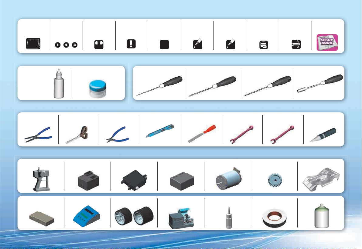
SYMBOLS USED
Part bags
used
Assemble in the
specified order
05
XRAY Premium
Silicone Oil 700cSt
(#359270) &
Silicone Oil 3000cSt
(#359303)
TOOLS REQUIRED
Pliers
(HUDY #189020)
Scissors
(HUDY #188990)
EQUIPMENT REQUIRED
Transmitter Steering ServoReceiver
Assemble left and
right sides the
same way
L=R
Diff. Grease
(HUDY #106211)
(HUDY #189010)
Pay attention
Side Cutters
here
TOOLS REQUIREDEQUIPMENT INCLUDED
Allen Wrench 1.5mm
(HUDY #111540)
Assemble as many
times as specified
(here twice)
2x
Hobby Knife File Turnbuckle 4mm
Speed Controller
Apply CA glue Apply oil
CA
Allen Wrench 2.0mm
(HUDY #112040)
1.5 mm
OIL
2.0 mm
Turnbuckle 3mm
(HUDY #181030)
Apply grease Ensure smooth
non-binding
movement
Allen Wrench 2.5mm
(HUDY #112540)
2.5 mm
(HUDY #181040)
Pinion Gear and Setscrew BodyshellElectric Motor
Follow Set-up
Book
Socket Driver 5.5mm
(HUDY #170055)
5.5 mm
Reamer
(HUDY #107600)
LiPo Battery Pack
Tire Truer
(HUDY #102003)
(HUDY #106230)
Fibre Tape
(HUDY #107870)
Lexan™ PaintBattery Charger Front & Rear Tires Bearing Oil
3
Page 4
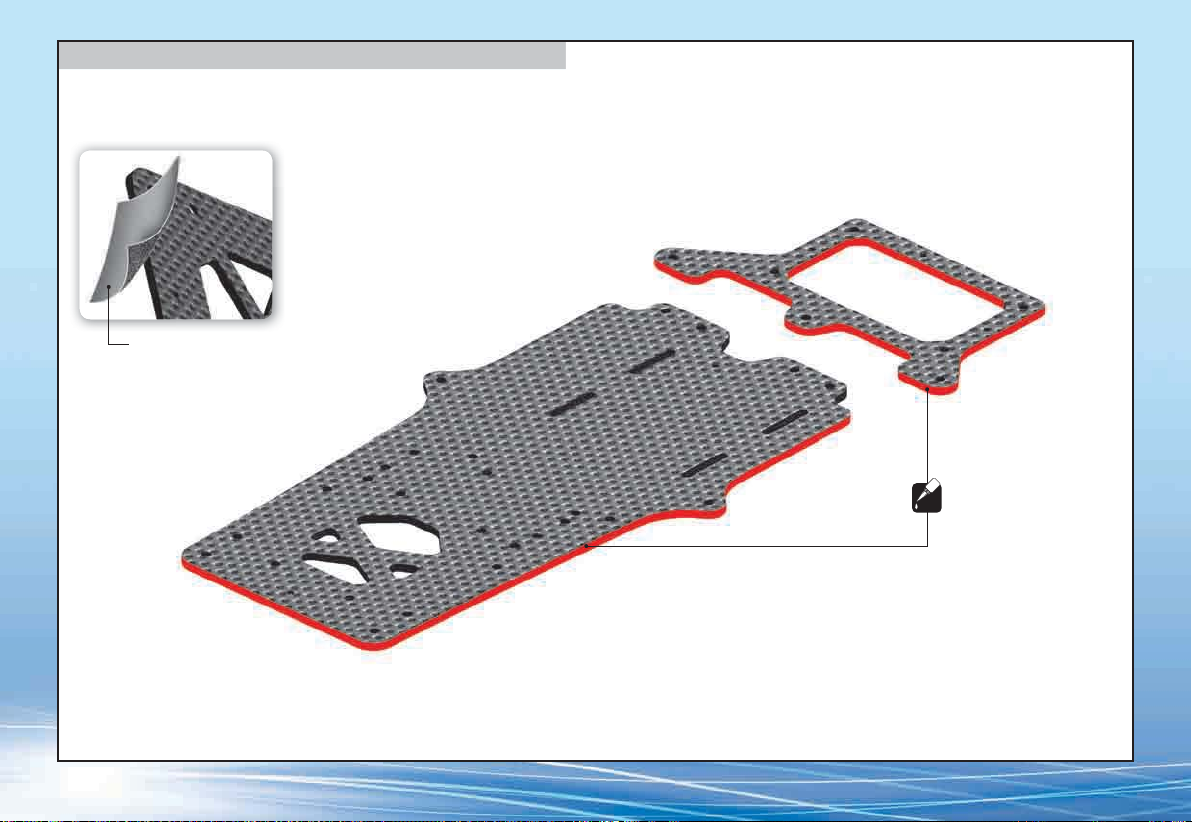
GRAPHITE PART PREPARATION
PREPARE ALL GRAPHITE PARTS
To protect and seal edges of graphite parts, sand edges smooth and then apply CA glue.
Fine sandpaper
Use fine sandpaper to sand smooth
the edges of all graphite parts.
Apply CA glue to all adges
CA
of the graphite parts.
4
Page 5
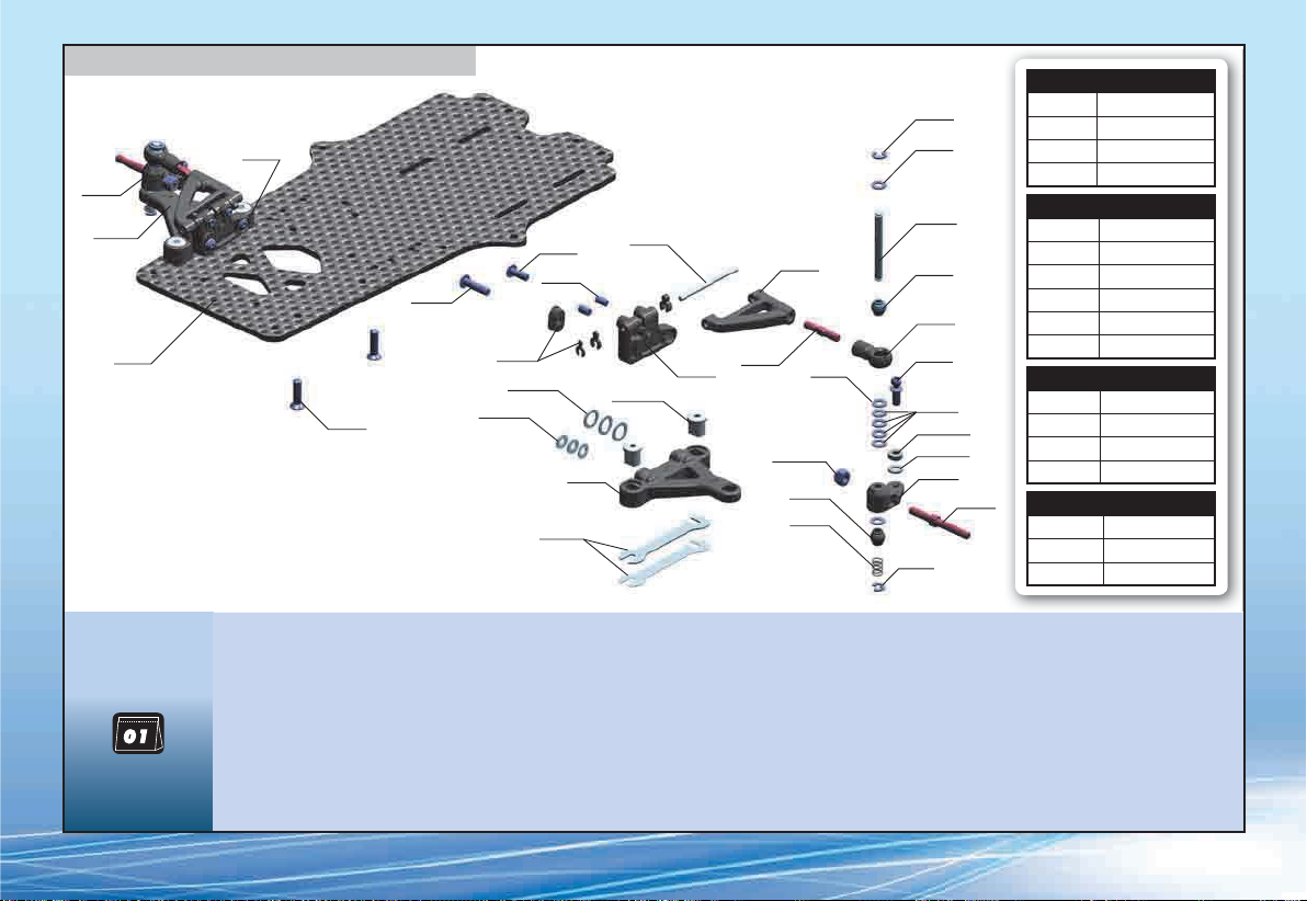
1. FRONT SUSPENSION
372011
372211
372112
371105
903312
902312
372315
373120-O
303121-O
902310
901304
372292
372293
372294
372122
377220
372316-O
372021
372620
372131
296530-O
373241
372180
372290
965019
372290
372280
373240
372130
372650
964032
303123-O
303122-O
372221
965019
375220
SUSPENSION ARMS
#372112 RIGHT - HARD
#372113 RIGHT - GRAPHITE
#372122 LEFT - HARD
#372123 LEFT - GRAPHITE
UPPER ARM MOUNTS
#372010 RIGHT - STANDARD
#372011 RIGHT - HARD
#372012 RIGHT - GRAPHITE
#372020 LEFT - STANDARD
#372021 LEFT - HARD
#372022 LEFT - GRAPHITE
FRONT COIL SPRINGS
#372180 C=3.5 - GOLD
#372181 C=4.0 - SILVER
#372182 C=5.0 - BLACK
#372183 C=6.0 - GREY
ALU ECCENTRIC BUSHINGS
#372316-O 0MM - STANDARD
#372317 0.5MM - OPTION
#372318 1.0MM - OPTION
BAG
303121-O ALU SHIM 3x6x0.5MM - ORANGE (10)
303122-O ALU SHIM 3x6x1.0MM - ORANGE (10)
303123-O ALU SHIM 3x6x2.0MM - ORANGE (10)
371105 X12‘15 CHASSIS - 2.5MM GRAPHITE
372011 COMPOSITE FRONT UPPER ARM MOUNT - RIGHT - HARD
372021 COMPOSITE FRONT UPPER ARM MOUNT - LEFT - HARD
372112 COMPOSITE SUSPENSION ARM FRONT LOWER - RIGHT - HARD
372122 COMPOSITE SUSPENSION ARM FRONT LOWER - LEFT - HARD
372130 COMPOSITE FRONT UPPER SUSPENSION ARM & BALL JOINT
372131 COMPOSITE FRONT UPPER SUSPENSION ARM - HARD
372180 FRONT COIL SPRING 3.6x6x0.5MM; C=3.5 - GOLD (2)
372211 COMPOSITE STEERING BLOCK - RIGHT - HARD - V2
372221 COMPOSITE STEERING BLOCK - LEFT - HARD - V2
372280 KING PIN (2)
372290 ALU SHIM 3.2x4.8x0.5 (4)
372292 STEEL SHIM 0.2MM - SILVER (2)
372293 STEEL SHIM 0.4MM - BLACK (2)
372294 STEEL SHIM 0.6MM - GOLD (2)
372315 COMPOSITE ECCENTRIC BUSHINGS + CASTER CLIPS (2)
372316-O ALU ECCENTRIC BUSHING 0.0MM - ORANGE (2)
372620 ADJ. TURNBUCKLE M3x17 MM - HUDY SPRING STEEL™ (2)
372650 BALL-END 4.2MM - THREADED - HUDY SPRING STEEL™ (2)
373120-O ALU SHIM 5.3x7.8x0.5MM - ORANGE (10)
373240 PIVOTBALL UNIVERSAL 6.0 MM - HUDY SPRING STEEL™(2)
373241 COMPOSITE PIVOTBALL 6.0 MM (2)
375220 FRONT WHEEL AXLE (2)
377220 FRONT UPPER PIVOT PIN 2x31MM (2)
296530-O ALU NUT M3 - ORANGE (10)
901304 HEX SCREW SB M3x4 (10)
902310 HEX SCREW SH M3x10 (10)
902312 HEX SCREW SH M3x12 (10)
903312 HEX SCREW SFH M3x12 (10)
964032 WASHER S 3.2 x 4.8 x 0.2 (10)
965019 E-CLIP 1.9 (10)
5
Page 6
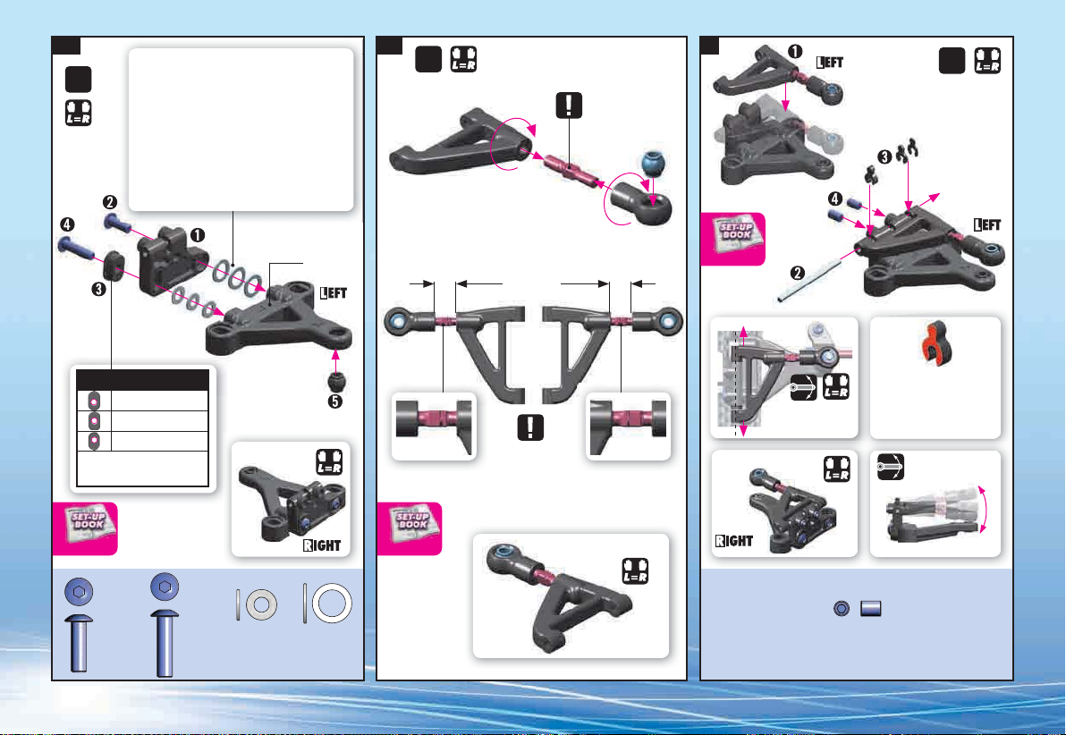
1. 2. 3.
2x
3x12
Upper Arm Position Adjustment Shims
The shims influence the camber gain change.
MORE shims = less camber gain, reduced initial
steering, reduced steering sensitivity (less twitchy).
LESS shims = more camber gain, increased initial
steering, increased steering sensitivity.
3x10
Use same shim thickness in left and right sides.
2x
NOTE
ORIENTATION
STEEL BALL
2x
1+0.5mm
2mm
5.3x7.8x0.5
3x6x0.5
REACTIVE CASTER SETTING
= 2.5°
= 5° INITIAL SETTING
= 7.5°
Use same bushings in left and
right sides.
CASTER CAMBER
902310
SH M3x10
902312
SH M3x12
ASSEMBLED VIEW
303121-O
SHIM 3x6x0.5
Marked “L“
COMPOSITE
BALL
373120-O
SHIM 5.3x7.8x0.5
6
7.2mm
NOTE ORIENTATION
7.2mm
ASSEMBLED VIEW
CASTER
ASSEMBLED VIEW
Make sure that
arm moves freely.
If the arm does not have
enough play, remove the clips
and thin the clips slightly with
sandpaper. The arms must have
free movement and not bind.
Moves freely
901304
SB M3x4
Page 7
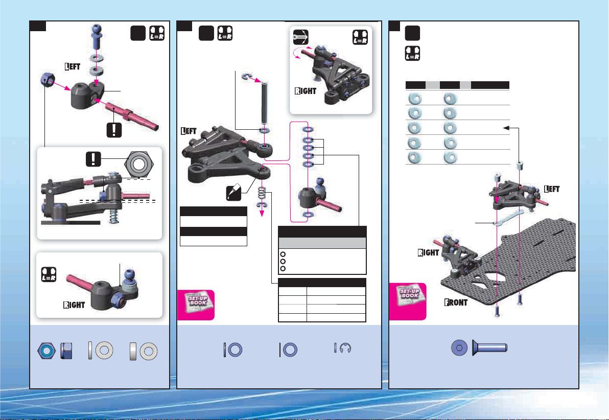
4. 5. 6.
2x 2x 2x
Moves freely
The number of shims used affects the ride
1mm
2mm
height of the car, so determine the proper
amount of shimming based on tire diameter.
Marked “L“
ASSEMBLED VIEW
NOTE
ORIENTATION
NOTE
0.5mm
0.5mm
0.2mm (4x)
ORIENTATION
The X12 has adjustable front track-width. There are 3 different
bushings - 0mm centric (included in kit), or 0.5mm or 1.0mm
eccentric (optional). Use the same bushing in front and rear, and
also use the same orientation of the bushing on both right and left
sides.
Use the proper bushing, to achieve requested front track-width.
+=
LEFT RIGHT TRACK WIDTH
-1mm
-0.5mm
0mm
+0.5mm
+1mm
165mm
166mm
167mm
168mm
169mm
Initial setting
The flat of the nut must be PARALLEL to the lower arm.
303122-O
SHIM 3x6x1
Marked “R“
303123-O
SHIM 3x6x2
ASSEMBLED VIEW
296530-O
ALU N M3
USE XRAY
SILICONE OIL
OIL
LOW traction & bumpy track
10K cSt (#359310 XRAY)
HIGH traction & flat track
30K cSt (#359330 XRAY)
RIDE HEIGHT
372290
S 3.2x4.8x0.5
0.2mm
FRONT RIDE HEIGHT ADJUSTMENT
INITIAL SETTING
above upper arm (0.5mm)
above steering block (1.3mm)
beneath steering block (0.2mm)
FRONT COIL SPRINGS
#372180 C=3.5 - GOLD
#372181 C=4.0 - SILVER
#372182 C=5.0 - BLACK
#372183 C=6.0 - GREY
964032
S 3.2x4.8x0.2
965019
C 1.9
The number of washers used affects the
ride height of the car, so determine the
proper amount of shimming based on
tire diameter.
INITIAL SETTING = 0.6mm washer
RIDE HEIGHT
TRACK-WIDTH
903312
SFH M3x12
7
Page 8
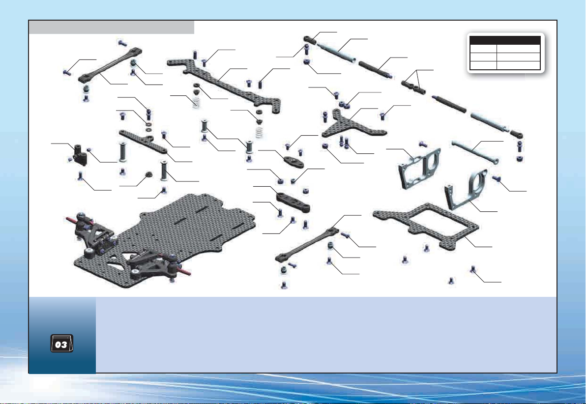
3. REAR SUSPENSION
902258
371190
372650
306219
303241
903306
373585
902306
306219
373084
373591
372650
901308
902306
372662
296530-O
378140
296530-O
373545
378150
902306
372662
SIDE SPRINGS
#373584 C=0.6 - SILVER
#373585 C=0.9 - GOLD
#373586 C=1.2 - BLACK
376300
901303
903308
373590
903306
902306
376352
376362-O
373073-O
903306
373092
296530-O
373092
903310
902306
373066
296530-O
371190
372650
373011
373030-O
903310
373021
903306
902258
371146
303241
903306
903306
BAG
303241 BALL UNIVERSAL 5.8 MM HEX (4)
306219 COMPOSITE SET OF SERVO SHIMS (4)
371146 LINK GRAPHITE 2.5MM REAR POD LOWER PLATE
371190 COMPOSITE POD LINK (2)
372650 BALL-END 4.2MM THREADED HUDY SPRING STEEL™(2)
372662 COMPOSITE BALL-JOINT 4.2 MM (4)
373011 ALU REAR BULKHEAD - MOTOR (RIGHT)
373021 ALU REAR BULKHEAD - LEFT
373030-O ALU REAR BULKHEAD BRACE - ORANGE
373066 ALU PIVOT BALL
373073-O ALU REAR BRACE MOUNT 16MM- ORANGE (2)
373084 LINK REAR BRACE - GRAPHITE 2.5MM
373092 COMPOSITE LOWER & UPPER PIVOT BRACE - LOW ROLL-CENTER
373545 X12‘15 REAR POD UPPER PLATE - GRAPHITE
373585 SIDE SPRING C=0.9 - GOLD (2)
373590 COMPOSITE SPRING HOLDER (2)
373591 COMPOSITE SIDE SPRING HOLDER (2)
376300 COMPOSITE ANTENNA MOUNT
376352 GR . PLATE FOR ANTENNA HOLDER
376362-O ALU ANTENNA HOLDER MOUNT - ORANGE (2)
378140 SIDE LINKAGE TUBE (2)
378150 SIDE SHOCK SHAFT (2)
296530-O ALU NUT M3 - ORANGE (10)
901303 HEX SCREW SB M3x3 (10)
901308 HEX SCREW SB M3x8 (10)
902258 HEX SCREW SH M2.5x8 (10)
902306 HEX SCREW SH M3x6 (10)
903306 HEX SCREW SFH M3x6 (10)
903308 HEX SCREW SFH M3x8 (10)
903310 HEX SCREW SFH M3x10 (10)
8
Page 9
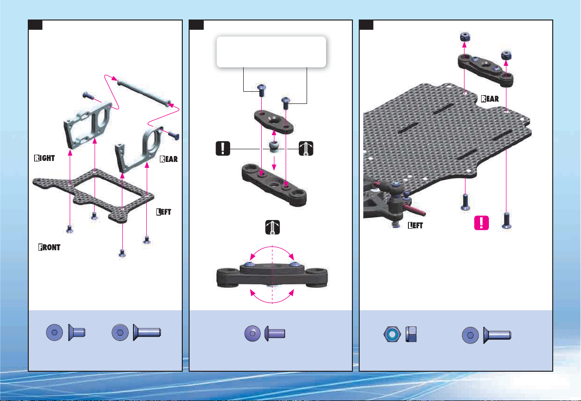
1. 2. 3.
Lightly tighten the screws so there is no free
play, but do not overtighten otherwise the
pivotball will not move freely.
3x10
3x10
NOTE
ORIENTATION
3x6
3x6
Ensure free, smooth movement without excessive freeplay.
DO NOT TIGHTEN FULLY
903306
SFH M3x6
903310
SFH M3x10
902306
SH M3x6
296530-O
ALU N M3
903310
SFH M3x10
9
Page 10

4. 5. 6.
2x 2x
DO NOT TIGHTEN FULLY,
PIVOTBALLS MUST TURN
FREELY.
ASSEMBLED VIEW
TIGHTEN
FULLY
10
903306
SFH M3x6
902258
SH M2.5x8
903306
SFH M3x6
Page 11

7. 8.
NOTE ORIENTATION
3x6x2
3x6x2
0.5mm
"CLICK"
306219
SHIM 3x6x2
901308
SB M3x8
296530-O
ALU N M3
902306
SH M3x6
903306
SFH M3x6
11
Page 12

9. 10. 11.
3x6x1
3x6x1
SHOCK MOUNTING POSITION
For alternative shock mounting
positions, see page 20.
12
902306
SH M3x6
296530-O
ALU N M3
306219
SHIM 3x6x1
901303
SB M3x3
903308
SFH M3x8
902306
SH M3x6
903306
SFH M3x6
Page 13

12. 13.
2x
OPTIONAL SIDE SHOCK
Optional side shock can be used to improve traction in
low- and medium-grip conditions.
2x
FACTORY PRE-ASSEMBLED
Add oil in each slot of the Derlin™ side shock tubes.
OIL
NOTE: Add oil only in the slots, not on the whole tube.
After assembling the side tubes, check for smooth operation.
NOTE: It is very important to re-oil the side tubes, as least once per race day.
NOTE: You may use different oil thicknesses depending on track conditions.
OILS
#359301 1000cSt
#359302 2000cSt
#359303 3000cSt
2x
For high grip: use softer oils
For low grip or asphalt: use harder oils
901310
SB M3x10
#359305 5000cSt
#359306 6000cSt
#359307 7000cSt
#359308 8000cSt
#359310 10000cSt
The angle of the side tubes has a fine effect on car
performance. The higher the angle, the stiffer it feels and
the less it rolls. The less (flatter) the angle, the softer it feels
and the more it rolls.
OPTIONAL PARTS (not included):
#378100 Side Shock Absorber Set
#302654 Ball End 4.9mm with 8mm Thread - V2 (2)
#303120 Set of Alu Shims (0.5mm, 1.5mm, 2.5mm)
#372651 Ball Universal 4.9mm - HUDY Spring Steel™ (2)
#902308 Hex Screw SH M3x8 (10)
902308
SH M3x8
3x6x2.5mm
372651
302654
3x6x2.5mm
13
Page 14

4. BALL DIFFERENTIAL
296530-O
375050-O
375030
963030
#375876 76T / 64P
#375878 78T / 64P
#375880 80T / 64P
#375896 96T / 64P
14
930138
SPUR GEARS
BAG
941438
375080
372070 COMPOSITE RIDE HEIGHT ADJUSTER SET (2)
375012 STEEL REAR AXLE SHAFT - HUDY SPRING STEEL™
375030 ALU REAR WHEEL HUB - RIGHT
375040 ALU REAR WHEEL HUB - LEFT
375050-O ALU DIFF HUB - ORANGE
375080 D-LOCK DIFF PLATE (2)
375090-O SET OF ALU SHIMS (0.5MM, 1.0MM, 2.0MM) - ORANGE
375896 COMPOSITE SPUR GEAR - 96T / 64P
375896
930130
941438
375080
296530-O ALU NUT M3 - ORANGE (10)
908258 HEX SCREW SOCKET HEAD CAP M2.5x8 (10)
930130 CARBIDE BALL 3.175MM (12)
930138 CARBIDE BALL-BEARING AXIAL F3-8 3x8x3.5
941438 HIGH-SPEED BALL-BEARING 1/4“x3/8“x1/8“ RUBBER SEALED (2)
951438 BALL-BEARING 1/4“ x 3/8“ x 1/8“ FLANGED (2)
963030 CONE WASHER ST 3x8x0.5 (10)
375012
951438
375090-O
372070
375090-O
375040
951438
908258
Page 15

1. 2.
Bearing Oil
(HUDY #106230)
OIL
Flanged
Bearing Oil
(HUDY #106230)
OIL
Flanged
Use additional shims to widen the rear
track-width. Use the same shims on
both sides. For initial assembly use
6.4x8.4x1mm shims.
Use these Ride Height
Adjusters for initial assembly.
0 2.02.5 1.5 1.0 0.5
951438
BB 1/4“x3/8“x1/8“
The axle must have a VERY small amount of side
play. If there is no side play, the axle may bind
and damage the ball-bearings.
TRACK-WIDTHRIDE HEIGHT
375090-O
6.4x8.4x1.0
908258
SCH M2.5x8
15
Page 16

3.
DIFFERENTIAL
Diff Grease
(HUDY #106211)
930130
B 3.1
NOTE
ORIENTATION
Bearing Oil
(HUDY #106230)
OIL
930138
BA 3x8
(HUDY #106211)
Diff Grease
(HUDY #106211)
Diff Grease
NOTE
ORIENTATION
(HUDY #106230)
941438
BB 1/4“x3/8“x1/8“
3.2mm
8.0mm 7.8mm
OIL
Bearing Oil
3.0mm
NOTE
ORIENTATION
Diff Grease
(HUDY #106211)
296530-O
ALU N M3
This nut affects the tightness and stiffness of the
rear differential.
Tighten the nut gently so the diff does not slip
under power, but do not overtighten or damage
to the diff balls and plates may occur.
963030
ST 3x8
16
Page 17

5. SHOCK ABSORBER
378011
SHOCK SPRINGS
#378092 C=1.5 - SILVER
#378093 C=1.8 - GOLD
#378094 C=2.1 - BLACK
378050-O
SHOCK OILS
#359210 100cSt
#359215 150cSt
#359220 200cSt
#359225 250cSt
#359230 300cSt
#359235 350cSt
#359240 400cSt
#359245 450cSt
BAG
378080
965015
378020
#359250 500cSt
#359255 550cSt
#359260 600cSt
#359270 700cSt
#359280 800cSt
#359290 900cSt
#359301 1000cSt
#359302 2000cSt
378001 SHOCK ABSORBER SET
378011 COMPOSITE SHOCK PARTS - FRAME
378020 ALU THREADED SHOCK BODY - HARDCOATED
378030-O ALU SHOCK BODY CAP - LOWER - ORANGE
378040-O ALU SHOCK ADJUSTABLE COLLAR - ORANGE
378050-O ALU SHOCK BODY CAP - UPPER - ORANGE
378011
378061
378011
378040-O
378061 SHOCK SHAFT
378070-O ALU SHOCK SPRING COLLAR - ORANGE
378071-O ALU SHOCK ADAPTER - ORANGE
378080 SHOCK RUBBER MEMBRANE (2)
378093 SHOCK SPRING - GOLD
971022
378030-O
378093
901303
378071-O
378011
378070-O
901303 HEX SCREW SB M3x3 (10)
965015 E-CLIP 1.5 (10)
971022 SILICONE O-RING 2x2 (10)
17
Page 18

1. 2. 3.
Carefully remove the shock piston from the
frame, and remove all excess plastic flash
OIL
Shock Oil
OIL
Shock Oil
ASSEMBLED VIEW
18
965015
C 1.5
971022
O 2x2
Page 19

4.
DEFAULT SHOCK SETTING FOR CENTER SHOCK ABSORBER
Follow the steps below to set the shock.
HALF TIGHTEN TIGHTEN FULLY
50%
Oil 700cSt
3~5x
UP & DOWN
➊➋➌➍➎➏
Extend the shock shaft
completely. Fill the shock
body with the shock oil.
Move the shock shaft up and
down a few times to release
the air bubbles trapped
beneath the piston.
Orient the filled shock
vertically for several
minutes with the shock
shaft fully extended. The
remaining air bubbles will
release.
Install the shock membrane
into the groove in the
upper shock cap.
Gently place the shock cap
assembly onto the filled
shock body. Excess oil will
spill from the shock. Screw
the shock cap onto the body
by only a few turns, approx.
50%. Excess oil will flow
through the hole in the
shock cap.
Gently push the shock shaft
completely into the shock
body. Excess oil will flow
through the hole in the
shock cap.
100%
➐
Keep the shock shaft
pushed in the shock body
and tighten the shock cap
completely.
Tighten the cap fully but
do not overtighten or the
rubber membrane may be
damaged. Make sure that
there is no oil leakage
after the cap is tightened.
19
Page 20

5.
ALTERNATIVE 1
SHORT SHOCK (REARWARD POSITION)
An innovative new feature is to change the center shock
front mounting position & shock length. By moving the
center shock mounts on the chassis to either the forward or
rearward position, the damping and steering characteristics
can be changed.
REARWARD shock position (SHORT shock):
Improved steering response, quicker direction changes.
FORWARD shock position (LONGER shock with adapter):
Improved driveability over bumps, improved on-power
traction.
DOWNSTOP ADJUSTMENT
The length of the shock absorber affects the amount of
rear downstop. To adjust, thread the ball-joint on or off the
bottom spring cap or adapter.
ALTERNATIVE 2 (INITIAL SETTING)
LONG SHOCK (FORWARD POSITION)
For the long shock
alternative, the shock
adaptor must be used.
20
SHORT
Press the collar FULLY onto
the end of the shock shaft and
tighten the M3x3 setscrew.
For initial setting,
thread fully.
901303
SB M3x3
LONG
5mm5mm
Press the collar FULLY onto
the end of the shock shaft and
tighten the M3x3 setscrew.
ADAPTER
For initial setting,
thread fully.
Page 21

37
6. FINAL ASSEMBLY
SPEED CONTROLLER
(not included)
STEERING SERVO
(not included)
301159-O
903310
372650
372503
FROM SERVO
372661
372503
RECEIVER
(not included)
372610-O
306219
372661
376255-O
903305
376310
376130
903305
LiPo BATTERY
(not included)
371320
309400
981210
306219
902310
TIRES
(not included)
375390
371320
309400
902308
MOTOR & PINION
(not included)
371200
903310
BAG
06
981210
301159-O ALU COUNTERSUNK SHIM - ORANGE (4)
305968~306000 PINION GEAR HARDCOATED 18~50T/64P
306219 COMPOSITE SET OF SERVO SHIMS (4)
309400 BODY CLIP FOR 5MM BODY POST (8)
371200 COMPOSITE CHASSIS PROTECTOR (2)
371320 COMPOSITE BODY POST (2)
372503 COMPOSITE SERVO SAVER - STIFF - SET
372610-O ALU ADJ. TURNBUCKLE M3x42 MM - ORANGE (2)
372650 BALL-END 4.2MM - THREADED - HUDY SPRING STEEL™ (2)
372661 COMPOSITE STEERING BALL-JOINT 4.2 MM OPEN (4)
375390 ALU HEX SCREW M3x8 FOR REAR WHEELS (6)
376130 COMPOSITE LiPo BATTERY BACKSTOP (2)
376255-O ALU SERVO MOUNT - ORANGE (2)
376310 FIBERGLASS SOLID ANTENNA ROD + CAP
951851
TIRES
(not included)
951851
296530-O
296530-O ALU NUT M3 - ORANGE (10)
902308 HEX SCREW SH M3x8 (10)
902310 HEX SCREW SH M3x10 (10)
903305 HEX SCREW SFH M3x5 (10)
903310 HEX SCREW SFH M3x10 (10)
951851 BALL-BEARING 1/8“ x 5/16“ x 9/64“ FLANGED (2)
981210 PIN 2x10 (10)
21
Page 22

1. 2. 3.
We recommend using a servo
for 1/12 pan cars.
3x6x1 for
Configuration
Left
initial setting
Configuration
Right
Servo
(not included)
ACKERMANN
2x
Servo screw
INITIAL POSITION
22
NOTE
ORIENTATION
Futaba
Hitec KO Propo
Use the adapter that
matches the steering servo.
306219
SHIM 3x6x1
Note the orientation of
servo saver when servo
is in neutral.
903310
SFH M3x10
90º
The position of the servo depends on the
weight of the electronics. If the car is
heavier on the right, use a left-side servo
position; if the car is heavier on the left,
use a right-side servo position.
903305
SFH M3x5
27.2mm
Left thread
27.2mm
Left thread
TOE
Page 23

4. 5. 6.
2x 2x 2x
NOTE
ORIENTATION
Note groove
position
NOTE
ORIENTATION
Note groove position
ACKERMANN
306219
SHIM 3x6x3
902310
SH M 3x10
981210
P 2x10
3x6x3
903310
SFH M 3x10
981210
P 2x10
23
Page 24

7. 8.
Motor
(not included)
PINION GEARS ALU HARDCOATED
#305968 18T / 64P (option)
#305969 19T / 64P (option)
#305970 20T / 64P (option)
Pinion
(not included)
#305971 21T / 64P (option)
#305972 22T / 64P (option)
#305973 23T / 64P (option)
#305974 24T / 64P (option)
#305975 25T / 64P (option)
#305976 26T / 64P (option)
#305977 27T / 64P (option)
#305978 28T / 64P (option)
#305979 29T / 64P (option)
#305980 30T / 64P (option)
#305981 31T / 64P (option)
#305982 32T / 64P (option)
Adjust the gear mesh
so there is appropriate
space between the
spur gear and pinion
teeth. There should be
a very small amount of
freeplay.
GEAR RATIO
#305983 33T / 64P (option)
#305984 34T / 64P (option)
#305985 35T / 64P (option)
#305986 36T / 64P (option)
#305987 37T / 64P (option)
#305988 38T / 64P (option)
There are two alternative battery positions,
inline and cross-chassis alignment.
Depending on the battery position, the
position of the electronics change as well.
See pages 25 and 26.
Speed controller
(not included)
➌
Double-sided tape
(not included)
Receiver wire
➊
Receiver
(not included)
➋
24
902308
SH M 3x8
901303
SB M3x3
After inserting the antenna rod, fully
tighten both setscrews. Do not overtighten
or you may strip the plastic.
Page 25

9A
LIPO BATTERY CONFIGURATION 1 Inline alignment:
INITIAL ASSEMBLY
Inline battery alignment improves cornering speed and reduces the chance that
the rear of the car will „diff out.“ Recommended for high-traction conditions.
Receiver
(not included)
Battery Pack
(not included)
Speed controller
(not included)
Battery Pack
(not included)
The battery pack has to be angled when
installing or removing it from the car.
Fibre Tape
(HUDY #107870)
(not included)
903305
SFH M3x5
25
Page 26

9B
LIPO BATTERY CONFIGURATION 2 Cross-chassis alignment:
Cross-chassis alignment provides more neutral handling, making the car less sensitive to set-up
changes and gives reduced steering responsive. Recommended for low- and medium-traction
conditions.
2x
Cut
26
Speed controller
(not included)
Battery Pack
(not included)
Receiver
(not included)
903305
SFH M3x5
Fibre Tape
(HUDY #107870)
(not included)
Page 27

10.
Front Wheels & Tires
ASSEMBLED VIEW
(not included)
375390
ALU SCH M3x8
951851
BB 1/8“x5/16“x9/64“
4x
OIL
296530-O
ALU N M3
Bearing Oil
(HUDY #106230)
Rear Wheels & Tires
(not included)
Gently tighten the wheel nuts
so the wheel turns freely, but
without excessive axial play.
NOT INCLUDED
To ensure that you always have access to the most up-to-date version of the XRAY Set-up Book, XRAY will
now be offering only the digital online version at our website at www.teamxray.com. By offering this online
version instead of including a hardcopy printed version in kits, you will always be assured of having the
most current updated version. The Set-up Book features the T-bar version of the XII, however the majority
of all set-up adjustments and theory are the same. we strongly recommend that you read and understand
the Set-up Book completely.
27
Page 28

ÊÊÊ
Ê
Ê
Ê
ÊÊÊÊÊÊÊ
Ê
,К,]КУдОдКiМХАЮКiМiАКЫ`К£x]КАЫ}]К/8КЗxдИУ
*" \ÊÓ£{Ç{{Ó{ää]Ê8\ÊÓ£{Ç{{Ó{ä£]ÊÝÀ>ÞJÀV>iÀV>°V
ЬЬЬ°v>ViL°VЙМi>ЭА>ЮКККККККККККККККЬЬЬ°МЬММiА°VЙМi>ЭА>ЮКККККККККККККÊÊÜ ÜÜ°ÞÕÌÕLi°VÉÝÀ>ÞÀ>V}
 Loading...