

Page 1

INSTRUCTION MANUALINSTRUCTION MANUALINSTRUCTION MANUAL
IT'S FUN, IT'S MICRO TRUC K , IT'S
4WD SHAFT-DRIVE4WD SHAFT-DRIVE 1/18 MICRO TRUCK 1/18 MICRO TRUCK4WD SHAFT-DRIVE4WD SHAFT-DRIVE 1/18 MICRO TRUCK 1/18 MICRO TRUCK4WD SHAFT-DRIVE 1/18 MICRO TRUCK
Page 2

391018.1 MANUAL Xray M18 prva a posledna CYAN MAGENTA YELLOW BLACK
1
CUSTOMER SUPPORT
R/C TIPS
• Read and fully understand the instruction manual before building.
• Always keep this instruction manual ready at hand for quick
reference, even after completing the assembly.
• Clear a work area for assembling the kit.
• Work on a light-colored towel so any dropped parts are easy to find.
• Only open bags of parts for the assembly section you are building;
do not open parts bags before required.
• Make sure all screws are tight, and check them periodically. Make
sure the chassis screws do not protrude below the chassis.
• For best performance, it is very important to ensure the free
movement of all parts.
• Tap or pre-thread composite parts when threading screws.
• Self-tapping screws cut threads into the parts when tightened. Do
not use excessive force when tightening self-tapping screws, or you
may strip out the thread in the plastic. We recommend you stop
tightening a screw when you feel some resistance.
Please support your local hobby shop, and ask them for advice. We at
XRAY Model Racing Cars support all local hobby dealers. We ask
you to purchase XRAY products at your hobby dealer whenever
possible, and give them your support as we do. If you have difficulty
finding XRAY products, please visit us at www.teamxray.com for
advice, or contact us via e-mail at support@teamxray.com, or
contact the XRAY distributor in your country.
In line with our policy of continuous product development, the exact specifications of the kit may vary. In the unlikely event of any problems
with your new kit, you should contact the model shop were you purchased it, quoting the part number. We reserve all rights to change any
specification without prior notice. All rights reserved.
XRAY EUROPE
Pred Polom 762
91101 Trenčín
Slovakia, EUROPE
Phone: 421-32-7440180
Fax: 421-32-7440179
Email: info@teamxray.com
XRAY USA
167 Turtle Creek Boulevard Suite C
Dallas, Texas 75207
USA
Phone: (800) 519-7221 * (214) 744-2400
Fax: (214) 744-2401
Email: xray@rcamerica.com
We have made every effort to make these instructions as easy to understand as possible. However, if you have any difficulties, problems, or
questions, please do not hesitate to contact the XRAY support team at info@teamxray.com. Also, please visit our web site at
www.teamxray.com to find the latest updates, set-up information, option parts, and many other goodies. We pride ourselves on taking
excellent care of our customers.
Page 3
2
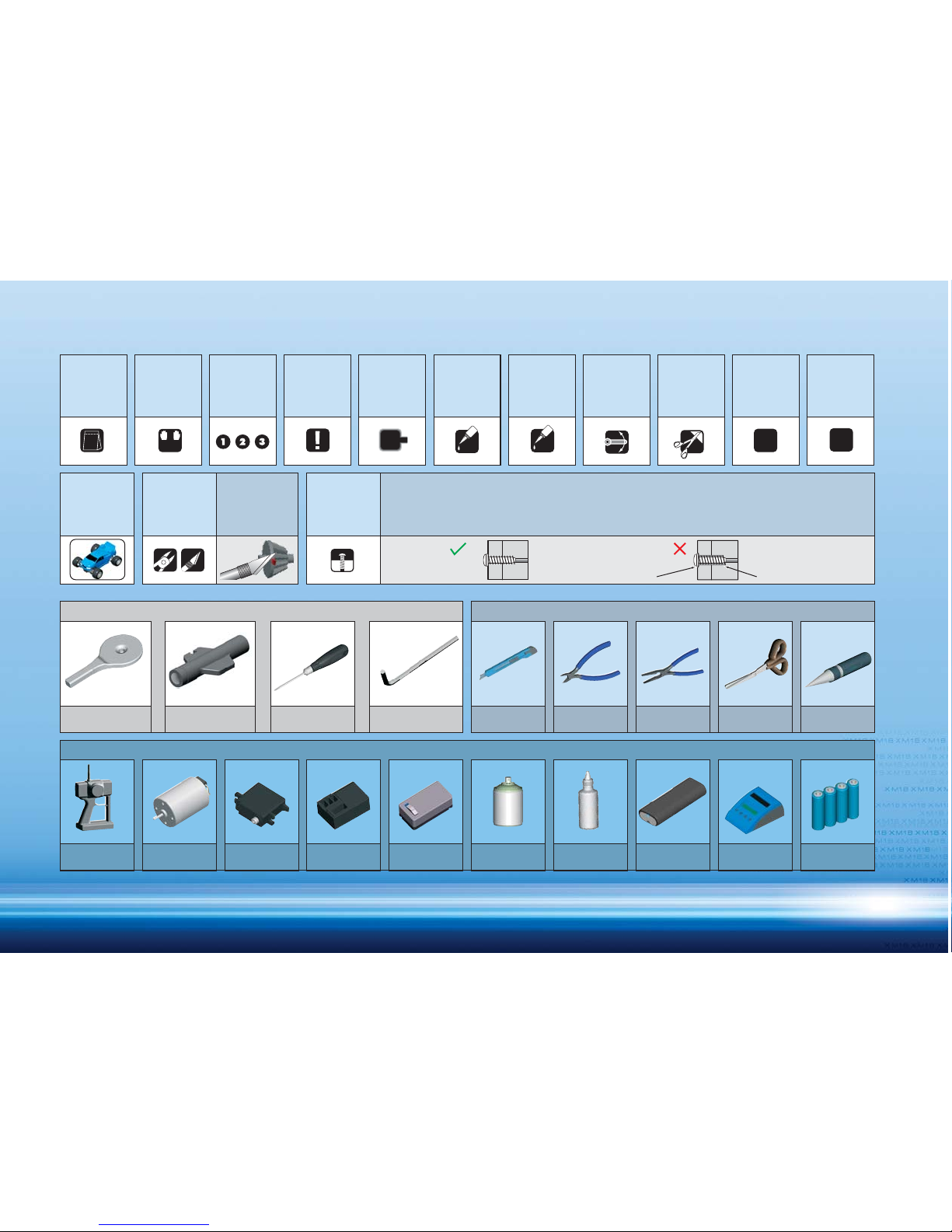
SYMBOLS USED
TOOLS REQUIRED
TOOLS INCLUDED
EQUIPMENT REQUIRED
Hobby Knife Side Cutters Needlenose Pliers Curved Scissors Hole Reamer
1:1
L=R
1
CA
2x
C
Self-tapping screws cut threads into the parts when being tightened. Excessive force may permanently damage
parts when tightening screws. It is recommended to stop tightening when the part is attached or when some
resistance is felt after the threaded portion enters the plastic.
Overtightened
CORRECT WRONG
The threads are stripped.
GR
Micro Servo
Receiver
Transmitter Micro Motor
6-Cell Micro
Battery Pack
Battery Charger Transmitter
Batteries
Micro Speed
Controller
CA GlueLexan Paint
(Typically AA type)(Ni-MH recommended)
Pin Assembly Tool Universal Tool Phillips Screwdriver 1.5mm Allen Wrench
Assemble as
many times
as specified
(here twice)
Cut off
remaining
material
Cut off
remaining
material from all
plastic parts.
Cut off
shadded
portion
Ensure smooth
non-binding
movement
Apply instant
glue
Apply instant
grease
Pivot ball
type used
Pay attention
here
Assemble in
the specified
order
Assemble left
and right
sides the
same way
Part bags
used
True-to-scale
diagram
Truck
orientation
Tighten screw
gently
Page 4
3
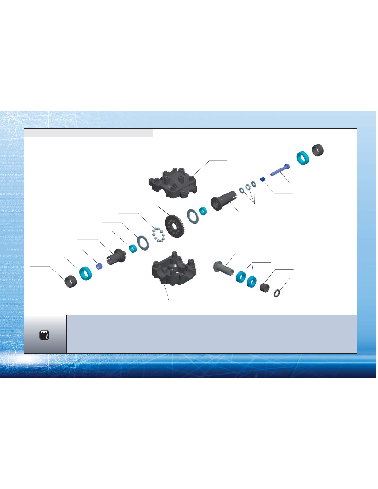
385062
385531
385531
970040
930610
385062
930020
385035
385095
930407
385002
960025
930812
385002
907270
385002
930025
385002
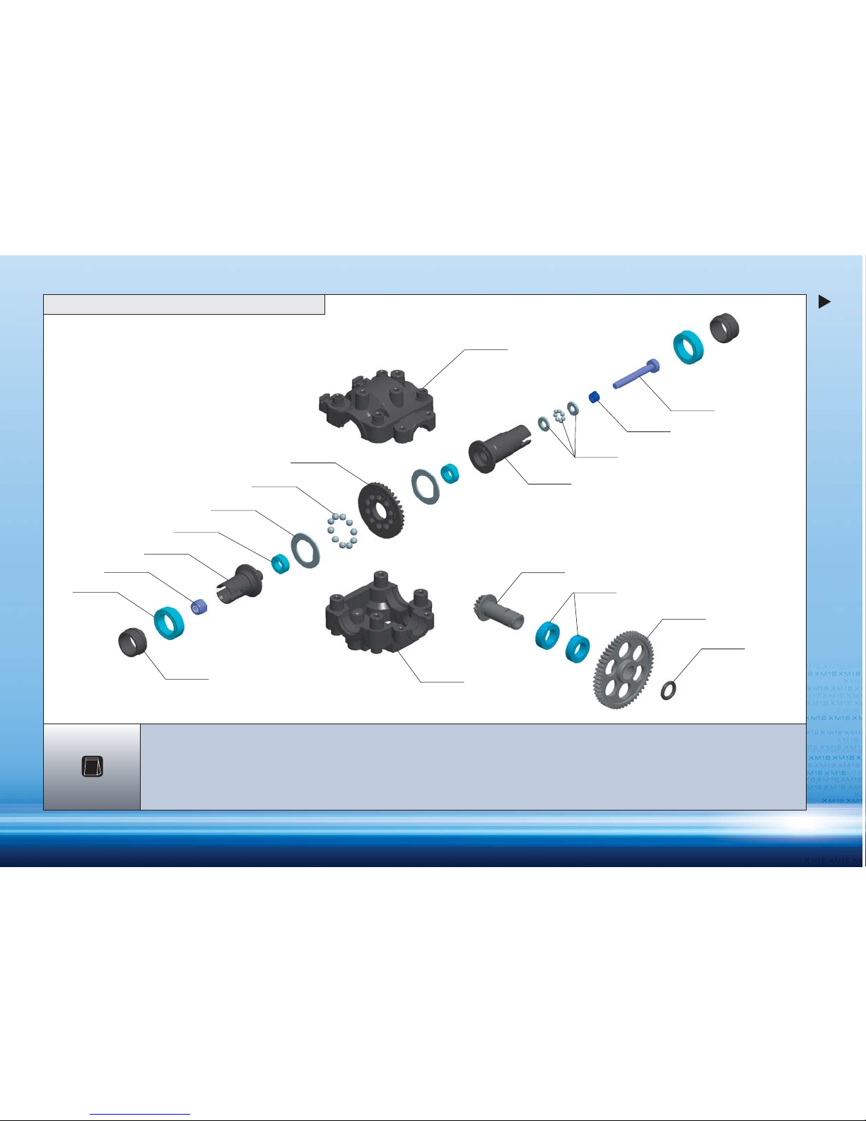
385002 COMPOSITE ADJUSTABLE BALL DIFFERENTIAL
385035 BEVELED DIFF. GEAR FOR BALL DIFF.
385062 GEARBOX CASE M18T
385095 BALL DIFF D - WASHER (2)
385531 MAIN DRIVESHAFT PINION GEAR & HUB M18T
907270 SCREW PHILLIPS 2.5x20 (10)
930020 BALL STEEL 2.4MM (24)
930025 BALL-BEARING AXIAL 2.5x5.4x0.8
930407 BALL-BEARING MR74ZZ 4x7x2.5 (2)
930610 BALL-BEARING MR106ZZ 6x10x3 (2)
930812 BALL-BEARING MR128ZZ 8x12x3.5 (2)
970040 O-RING 4x1 (10)
960025 NUT M2.5 (10)
1
BAG
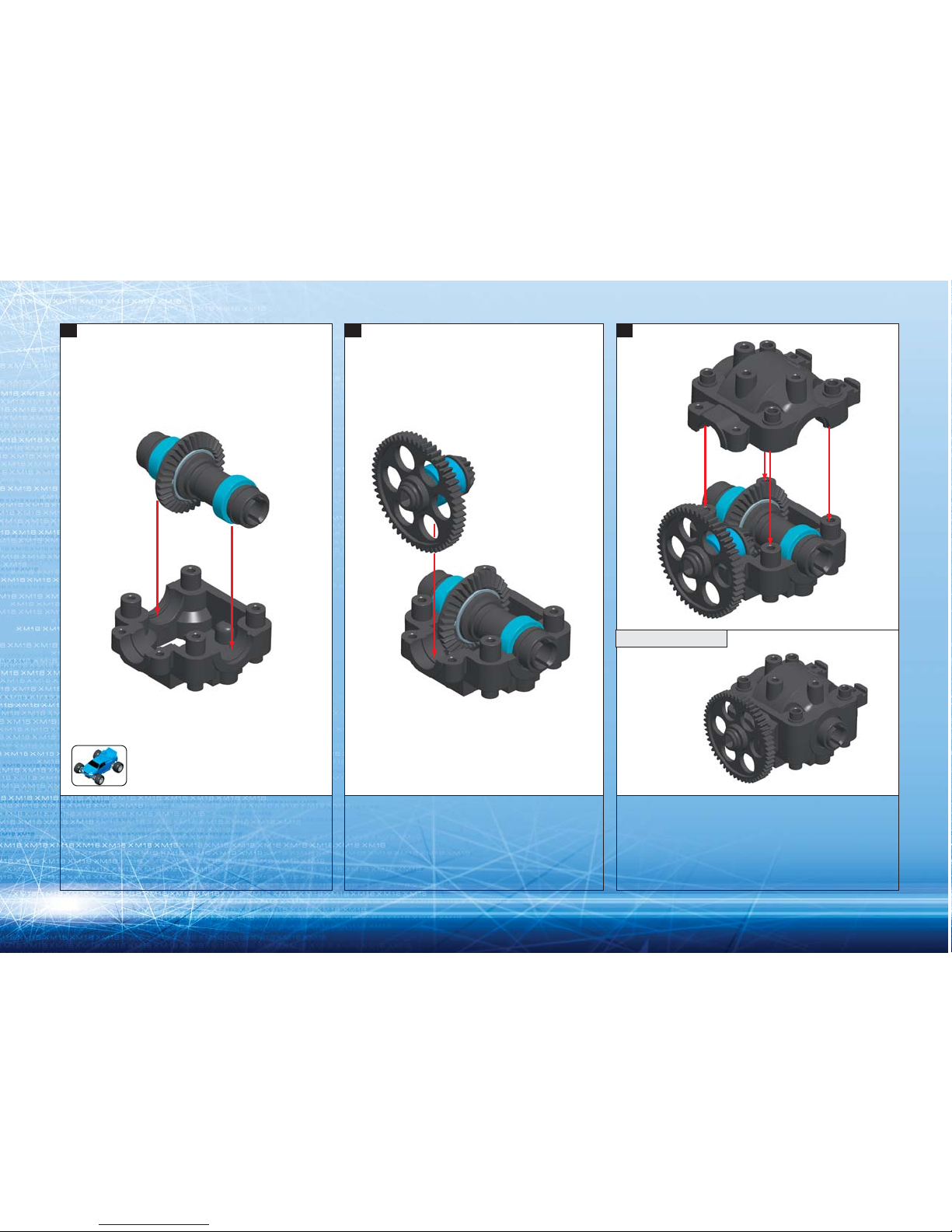
1. FRONT DIFFERENTIAL
Page 5
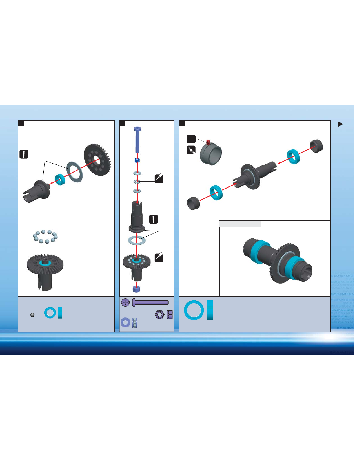
4
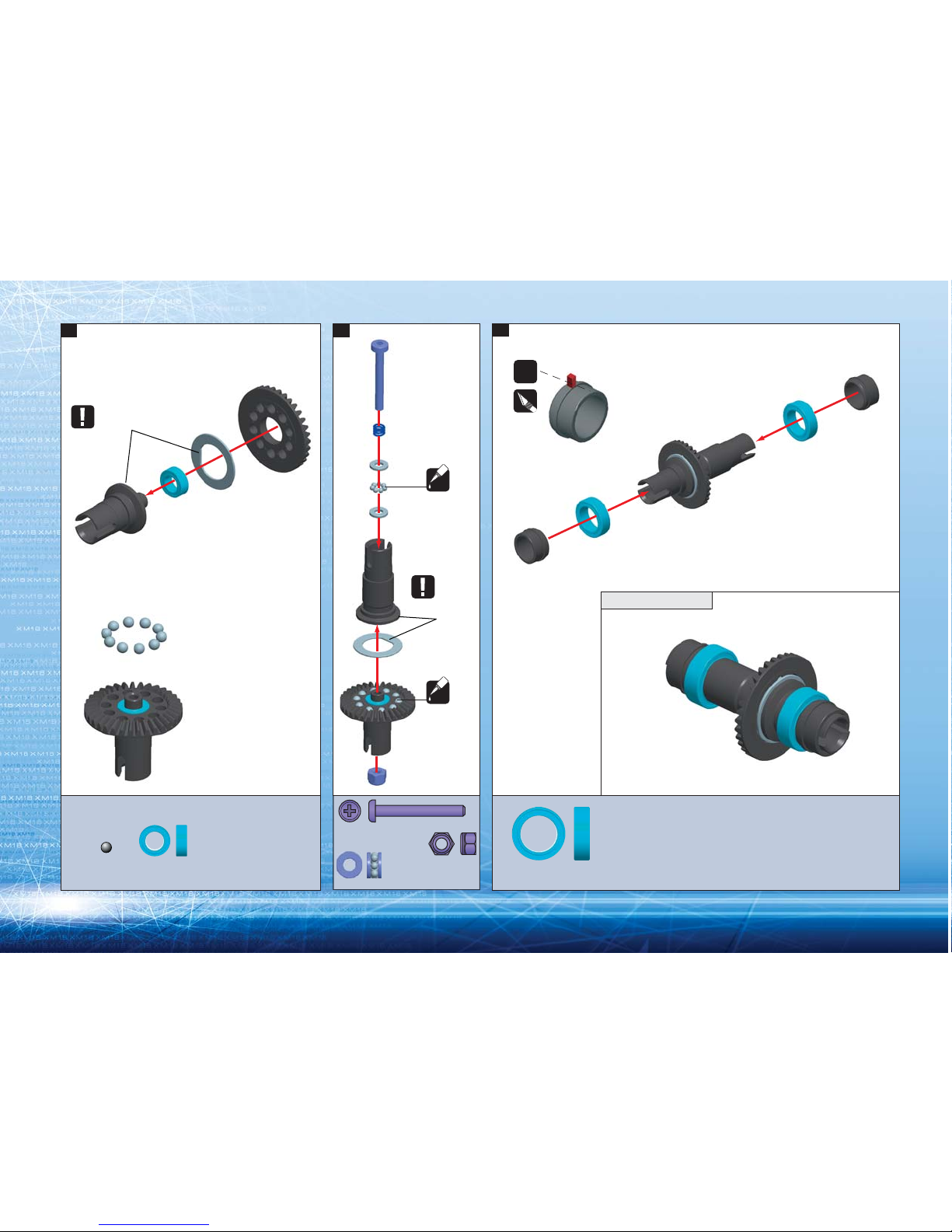
3.
CUT OFF
ALIGN FLAT SPOTS
ALIGN FLAT
SPOTS
2x
GR
GR
1. 2.
ASSEMBLED VIEW
FACTORY PRE-ASSEMBLED
930812
BB 8x12x3.5
930020
B 2.4
960025
N M2.5
930025
BA 2.5x0.8
907270
2.5x20
907270
2.5x20
930407
BB 4x7x2.5
Page 6
5
CUT OFF
4. 5. 6.
ASSEMBLED VIEW
930610
BB 6x10x3
970040
O 4x1
ORIENTATION
ASSEMBLED VIEW
NOTE
ORIENTATION
Page 7
6
385035
930020
385095
930407
385002
960025
930812
970040
385062
385002
385754
930610
385531
907270
385002
930025
385002
385062
2. REAR DIFFERENTIAL
BAG
2
385002 COMPOSITE ADJUSTABLE BALL DIFFERENTIAL
385035 BEVELED DIFF. GEAR FOR BALL DIFF.
385062 GEARBOX CASE M18T
385095 BALL DIFF D - WASHER (2)
385531 MAIN DRIVESHAFT PINION GEAR & HUB M18T
385754 SPUR GEAR 54T / 48
907270 SCREW PHILLIPS 2.5x20 (10)
930020 BALL STEEL 2.4MM (24)
930025 BALL-BEARING AXIAL 2.5x5.4x0.8
930407 BALL-BEARING MR74ZZ 4x7x2.5 (2)
930610 BALL-BEARING MR106ZZ 6x10x3 (2)
930812 BALL-BEARING MR128ZZ 8x12x3.5 (2)
970040 O-RING 4x1 (10)
960025 NUT M2.5 (10)
Page 8
7
960025
N M2.5
930025
BA 2.5x0.8
907270
2.5x20
907270
2.5x20
930020
B 2.4
930407
BB 4x7x2.5
930812
BB 8x12x3.5
3.
CUT OFF
2x
FACTORY PRE-ASSEMBLED
ALIGN FLAT SPOTS
ALIGN FLAT
SPOTS
GR
GR
1. 2.
ASSEMBLED VIEW
Page 9
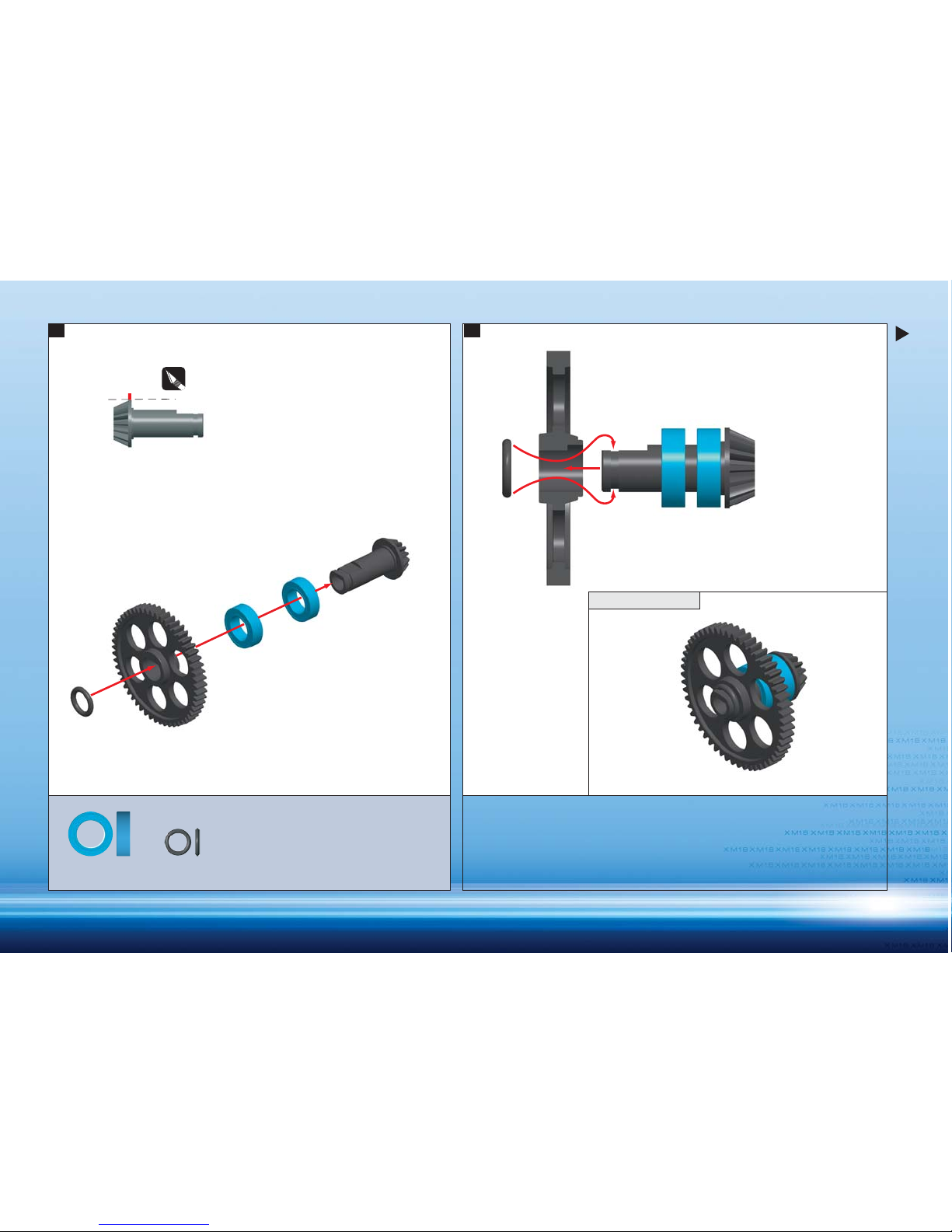
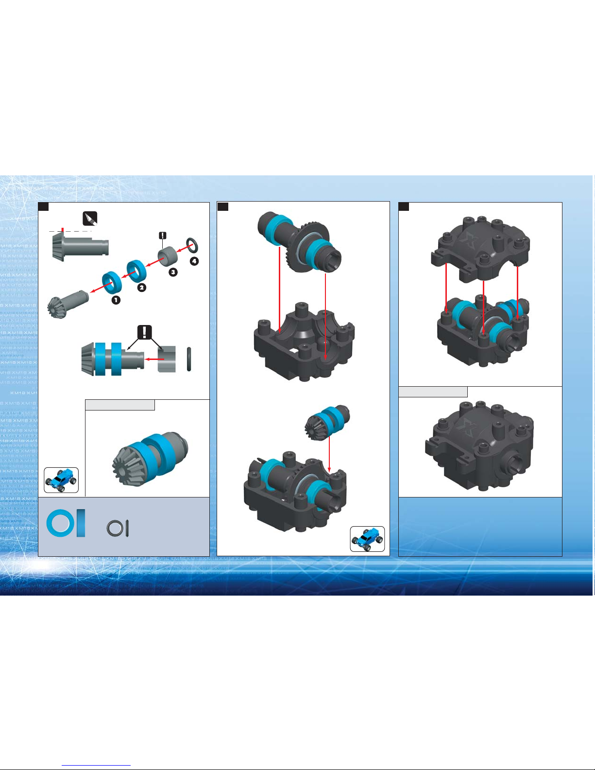
8
4. 5.
ASSEMBLED VIEW
930610
BB 6x10x3
970040
O 4x1
CUT OFF
Page 10
9
6. 7. 8.
ASSEMBLED VIEW
Page 11
10
906258
905260
381210
381160
387410
USE REMAINING PIVOT BALLS
IN OTHER SECTIONS !!!
905208
981208
387410
382200
930610
387410
383120
905208
383150
905264
385300
385300
901325
383240
387410
905212
905210
382650
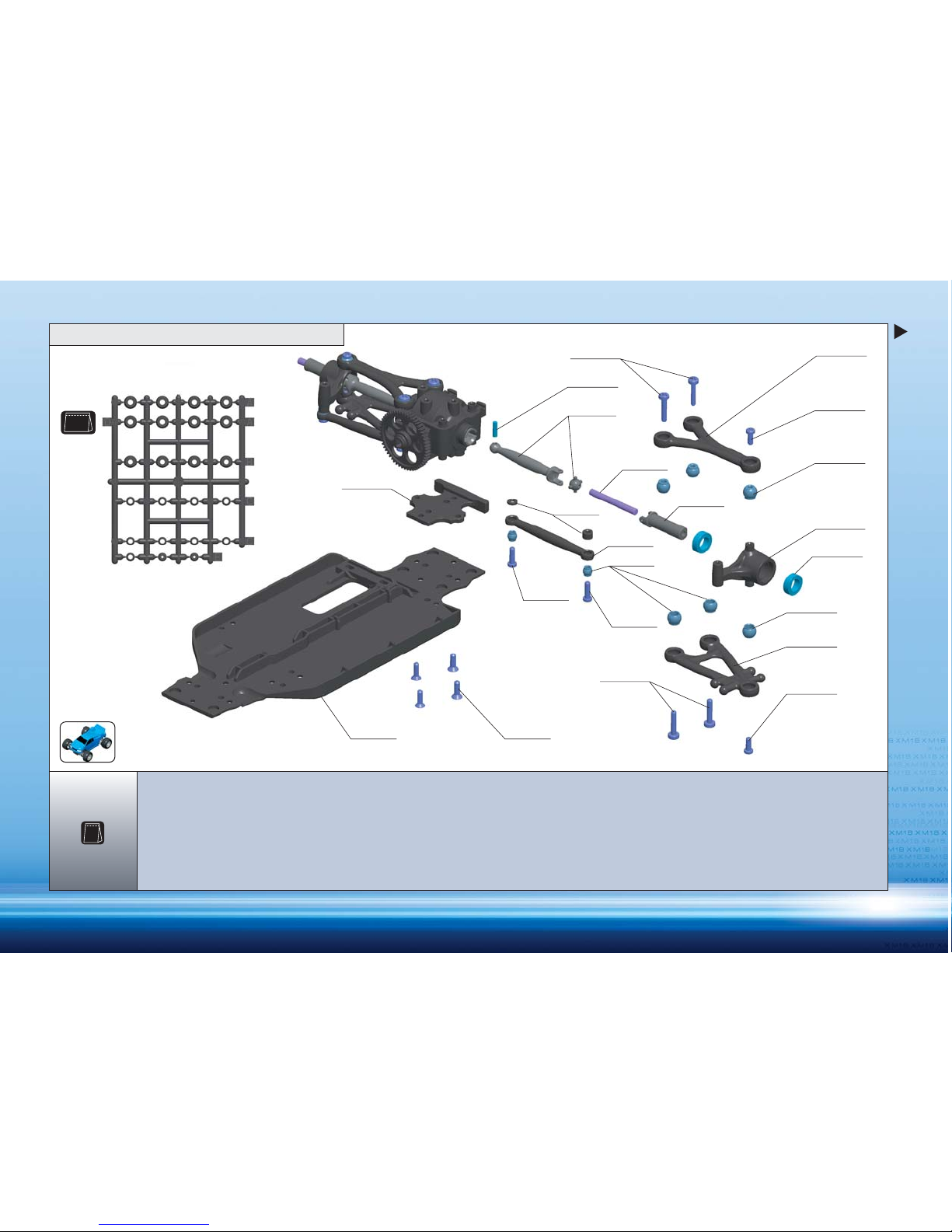
3. REAR SUSPENSION
BAG
3
BAG
3.1
381160 COMPOSITE MICRO CHASSIS M18T
381210 LOWER FRONT & REAR BUMPER M18T
382200 COMPOSITE SUSPENSION BLOCK, L+R (2)
382650 SET OF STEERING PARTS
383120 SET OF REAR LOWER SUSPENSION ARMS M18T
383150 SET OF REAR UPPER SUSPENSION ARMS M18T
383240 LINKAGE REAR M18T (2)
385300 COMPOSITE DRIVE SHAFT SET M18T (2)
387410 SET OF COMPOSITE PIVOT BALLS M18T
901325 HEX SCREW SB M3x25 (10)
905208 SCREW PHILLIPS 2.2x8 (10)
905210 SCREW PHILLIPS 2.2x10 (10)
905212 SCREW PHILLIPS 2.2x12 (10)
905260 SCREW PHILLIPS 2.5x10 (10)
905264 SCREW PHILLIPS 2.5x14 (10)
906258 SCREW PHILLIPS FH 2.5x8 (10)
930610 BALL-BEARING MR106ZZ 6x10x3 (2)
981208 PIN 2x8 (10)
Page 12
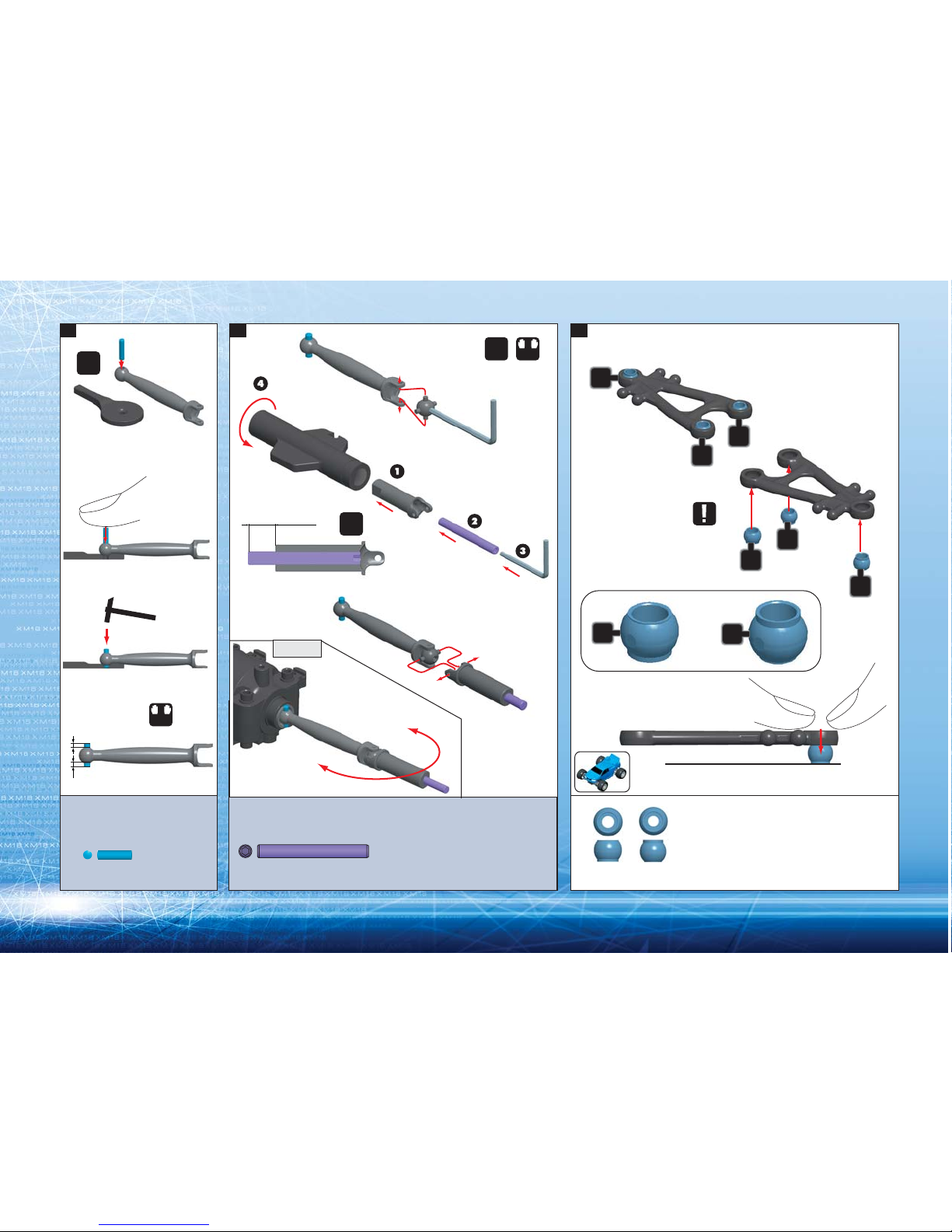
11
901325
SB 3x25
2.
CHECK
L=R
2x
NOTE ORIENTATION
OF ALL PIVOT BALLS
DETAIL
6 mm
1:1
981208
P 2x8
1. 3.
SAME
LENGTH
LEFT LOWER ARM
RIGHT LOWER ARM
L
L=R
R
2x
A
A
A
A
B
AB
B
B
A
Page 13

12
A
A
A
A
NOTE ORIENTATION
OF ALL PIVOT BALLS
B
B
905208
2.2x8
930610
BB 6x10x3
TIGHTEN
GENTLY
DETAIL
B
A
4. 5.
RIGHT
LEFT
RIGHT LEFT
6.
7.
RIGHT UPPER ARM
LEFT UPPER ARM
AB
Page 14

13
905264
2.5x14
905264
2.5x14
905260
2.5x10
905210
2.2x10
905210
2.2x10
905212
2.2x12
1mm
3mm
905260
2.5x10
905212
2.2x12
C
C
930610
BB 6x10x3
8. 9. 10.
11.
C
TIGHTEN
GENTLY
2x
L=R
1:1
Page 15

14
906258
2.5x8
12. 13.
ASSEMBLED VIEW
NOTE ORIENTATION
CUT OFF
DETAIL
DETAIL
Page 16

15
387410
BAG
3.1
981208
381210
905260
387410
385300
905208
387410
382120
382200
930610
382150
387410
905208
905264
906258
905262
901325
385522
381210 LOWER FRONT & REAR BUMPER M18T
382120 SET OF FRONT LOWER SUSPENSION ARMS M18T
382150 SET OF FRONT UPPER SUSPENSION ARMS M18T
382200 COMPOSITE SUSPENSION BLOCK, L+R (2)
385300 COMPOSITE DRIVE SHAFT SET M18T (2)
385522 ALU MAIN DRIVESHAFT M18T
387410 SET OF COMPOSITE PIVOT BALLS M18T
901325 HEX SCREW SB M3x25 (10)
905208 SCREW PHILLIPS 2.2x8 (10)
905260 SCREW PHILLIPS 2.5x10 (10)
905262 SCREW PHILLIPS 2.5x12 (10)
905264 SCREW PHILLIPS 2.5x14 (10)
906258 SCREW PHILLIPS FH 2.5x8 (10)
930610 BALL-BEARING MR106ZZ 6x10x3 (2)
981208 PIN 2x8 (10)
BAG
4
4. FRONT SUSPENSION
USE REMAINING PIVOT BALLS.
Page 17

16
981208
P 2x8
1.
SAME
LENGTH
L
L=R
R
2x
2.
L=R
2x
CHECK
6 mm
1:1
3.
D
NOTE ORIENTATION
OF ALL PIVOT BALLS
LEFT LOWER ARM
RIGHT LOWER ARM
A
B
A
A
B
DETAIL
D
B
AB
B
D
B
D
901325
SB 3x25
Page 18

17
905208
2.2x8
930610
BB 6x10x3
4. 5. 6.
7.
A
A
A
B
B
A
RIGHT UPPER ARM
LEFT
RIGHT
RIGHT LEFT
LEFT UPPER ARM
NOTE ORIENTATION
OF ALL PIVOT BALLS
TIGHTEN
GENTLY
L=R
2x
DETAIL
B
A
AB
Page 19

18
930610
BB 6x10x3
8. 9. 10.
LEFT
RIGHT REAR
906258
2.5x8
905264
2.5x14
905264
2.5x14
905260
2.5x10
905260
2.5x10
905262
2.5x12
4x
TIGHTEN
GENTLY
DETAIL
905262
2.5x12
Page 20

19
382650
905208
901262
387410
905214
382650
907310
387410
930508
387410
382650
905212
906258
906258
382090
382650
905208
905212
387410
905214
906258
382090
381180
389182
from XRAY Power Pack
906258
906210
from XRAY
Power Pack
387410
382620
381180 COMPOSITE TOP DECK M18T
382090 SHOCK TOWER FRONT & REAR M18T
382620 ADJUSTABLE TURNBUCKLE 40MM
382650 SET OF STEERING PARTS
387410 SET OF COMPOSITE PIVOT BALLS M18T
389182 XRAY MICRO SPEED CONTROLLER 300R WITH REVERSE
901262 HEX SCREW SB M2.5x12 (10)
905208 SCREW PHILLIPS 2.2x8 (10)
905212 SCREW PHILLIPS 2.2x12 (10)
905214 SCREW PHILLIPS 2.2x14 (10)
906210 SCREW PHILLIPS FH 2.2x10 (10)
906258 SCREW PHILLIPS FH 2.5x8 (10)
907310 SCREW PHILLIPS M3x10 (10)
930508 BALL-BEARING MR85ZZ 5x8x2.5 (2)
BAG
5
5. STEERING SYSTEM
387410
BAG
3.1
USE REMAINING PIVOT BALLS.
Page 21

20
CC
905208
2.2x8
901262
SB 2.5x12
1. 2. 3.
29.7mm
2mm
B
C
B
C
1:1
1:1
2x
Page 22

21
907310
3x10
906258
2.5x8
905208
2.2x8
5.4. 6.
DETAIL
NOTE:
Rear shocktower
is larger than
front shocktower
Page 23

22
1:1
7. 8. 9.
906210
2.2x10
906258
2.5x8
905212
2.2x12
905214
2.2x14
Speed Controller such as 389182
from XRAY Power Pack
906210
905212
2.2x12
905214
2.2x14
5mm
5mm
7mm
7mm
from XRAY
Power Pack
or use double-sided tape
2x
Page 24

23
388110
388110
388191
388110
388110
388160
387410
388110
388166
SHOCK BODY
FACTORY PRE-ASSEMBLED
388110
388191
388080
965015
388110
front (short)
front (short)
rear (long)
rear (long)
rear (long)
front (short)
387410 SET OF COMPOSITE PIVOT BALLS M18T
388080 MICRO SHOCKABSORBER MEMBRANES (4)
388100 SHOCK ABSORBER-SET M18T (4)
388110 COMPOSITE FRAME SHOCK PARTS (2)
388160 FRONT MICRO SHOCK SHAFT M18T (2)
388166 REAR MICRO SHOCK SHAFT M18T (2)
388191 XRAY SPRING-SET M18T
965015 E-CLIP 1.5 (10)
BAG
6
6. SHOCK ABSORBERS
387410
BAG
3.1
USE REMAINING PIVOT BALLS.
Page 25

24
1.
3.2.
DETAIL STEP 3
Fill until shock oil
nearly overflows
Gently move the
piston up and
down to get
rid of air bubbles
Pull down
the piston
Be careful not to damage
the shock rod
OIL
4x
965015
C 1.5
1 mm
DETAIL
short
short
long
long
2x
2x
4x
OIL
FRONT
REAR
Grip at TOP of threads
Page 26

25
2x 2x
C
4. 5.
4x
Insert clips according
to track conditions
Front spring (short)
IMPORTANT
Both front shocks must be
the same overall length.
Rear spring (long)
FRONT SHOCK (short)
REAR SHOCK (long)
Use tool for easy clip
installation and removal
Thread the shock
cap onto the shock
body. Excess oil
should spill out.
IMPORTANT
Both rear shocks must be
the same overall length.
Pull down the piston.
B
C
B
C
Page 27

26
388100 SHOCK ABSORBER-SET M18T (4)
389123 XRAY BATTERY 6-CELL - 1100mAh NiMH - 7.2V
389162 XRAY MICRO MOTOR 300 SUPERSIZE WITH PLUG
389170 XRAY XMS01MG MICRO SERVO - METAL GEAR
389400 MICRO BODY CLIP (10)
389610 MICRO M18T SLICK TIRE & INSERT (4+4)
389930 WHEEL STARBURST AERODISK - M18T (4)
901260 HEX SCREW SB M2.5x10 (10)
901303 HEX SCREW SB M3x3 (10)
BAG
7
382050 COMPOSITE MOTOR HOLDER M18T
382411 ANTI-ROLL BAR FRONT & REAR 1 MM
382500 MICRO SERVO SAVER
382650 SET OF STEERING PARTS
385702 COMPOSITE PINION SET (9,10,11,12)
386120 COMPOSITE BATTERY HOLDER SET M18T
386210 COMPOSITE SERVO MOUNT M18T (2)
386310 ANTENNA
387410 SET OF COMPOSITE PIVOT BALLS M18T
905206 SCREW PHILLIPS 2.2x6 (10)
905208 SCREW PHILLIPS 2.2x8 (10)
905210 SCREW PHILLIPS 2.2x10 (10)
905258 SCREW PHILLIPS 2.5x8 (10)
906258 SCREW PHILLIPS FH 2.5x8 (10)
907306 SCREW PHILLIPS M3x6 (10)
960030 NUT M3 (10)
961022 WASHER S 2.2 (10)
961025 WASHER S 2.5 (10)
389170
from XRAY
Power Pack
386210
386120
389123
from XRAY Power Pack
961022
961025
905258
905208
905258
382500
389162
from XRAY Power Pack
382050
907306
385702
901303
905210
386120
389400
905206
388100
901260
382650
389930
389610
960030
389610
382411
387410
905210
388100
387410
382411
901260382650
7. FINAL ASSEMBLY
906258
from Servo
386310
387410
BAG
3.1
USE REMAINING PIVOT BALLS.
Page 28

27
E
B
E
1 mm
Rear
REAR ANTI-ROLL BAR
Front & Rear
Front & Rear
Front
1:1
Push in wire until
flush with end of E
1. 2. 3.
8x
901260
SB 2.5x10
961022
S 2.2
905206
2.2x6
4x
Page 29

28
FRONT ANTI-ROLL BAR
REAR ANTI-ROLL BAR
FINAL ASSEMBLY
FRONT ANTI-ROLL BAR
FINAL ASSEMBLY
Add to INNER
mounts
4. 5. 6.
961022
S 2.2
905206
2.2x6
Page 30

29
905210
2.2x10
905210
2.2x10
905208
2.2x8
FRONT
SHOCKS
(SHORT)
REAR
SHOCKS
(LONG)
Small ring
Large ring
INITIAL POSITIONSINITIAL POSITIONS
Use servo horn
for your servo.
7. 8.
9.
Page 31

30
from XRAY Servo Saver
382500
10. 11.
90°
905258
2.5x8
961025
S 2.5
from Servo
Page 32

31
13.12.
ASSEMBLED VIEW
901303
SB M3x3
907306
3x6
905258
2.5x8
USE XRAY 300 MICRO
MOTOR INCLUDED
IN XRAY M18T POWER
PACK #389102
TIGHTEN
GENTLY
11 T
PRE-THREAD THE PINION
USE 300 MICRO MOTOR
TIP
1mm
Page 33

32
SPUR
GEAR
PINION
GEAR
FINAL
RATIO
ACCELERATION
SPEED
09
10
11
12
13
14
54
x
x
x
x
o
o
x - INCLUDED WITH KIT
o - AVAILABLE OPTION
15.00
13.50
12.27
11.25
10.38
09.64
INTERNAL RATIO 1:2.5
14.TECH TIP
PINION GEAR
SPUR GEAR
To change pinion gears, first remove your motor along with
the old pinion gear. Install the new pinion gear and reinstall your motor. When installing the two 2x8mm button
head screws to secure the motor mount to the chassis, do
not fully tighten them. Leave them just loose enough so you
can slide the motor in and out towards the spur gear. Make
sure there is sufficient space between spur gear and pinion
to allow for a small amount of backlash so the gears do not
bind, see the diagram. When you have the motor in this
position, you may then fully tighten the motor mount screws.
Always check the gear mesh one more time to confirm that
the motor did not move when tightening the screws.
THE MOTOR STAND IS ADJUSTABLE:
1. RELEASE SCREWS FROM THE BOTTOM OF CHASSIS
2. MOVE THE MOTOR STAND AS NEEDED
3. TIGHTEN THE SCREWS
ADJUST MOTOR STAND SO GEARS MESH SMOOTHLY
905258
2.5x8
Page 34

33
(NOT INCLUDED)
15. 16. 17.
INSTALL RECEIVER
(NOT INCLUDED)
DOUBLE-SIDED
TAP E
4x
DO NOT USE
TOO MUCH GLUE
CA
ALIGN TAB AND SLOT
BEFORE TIGHTENING SCREW
CUTAWAY ASSEMBLED VIEW
960030
M3
Page 35

34
ELECTRONICS ASSEMBLY
BATTERY PACK
STEERING
SERVO
ANTENNA WIRE
RECEIVER
RECEIVER
SPEED
SPEED
CONTROL
CONTROL
M18T POWER PACK ASSEMBLY SHOWN
USE XRAY M18T POWER PACK #389102 THAT INCLUDES ALL
ELECTRONICS REQUIRED FOR OPERATION. (RECEIVER & TRANSMITTER ARE NOT INCLUDED)
INSTALL ELECTRONICS ACCORDING
TO MANUFACTURER'S INSTRUCTIONS
MOTOR
MOTOR
RECEIVER
1 CH
2 CH
SPEED
CONTROL
MOTOR
TIP
Page 36

35
HOLE FOR
BODY POSTS
4.5mm
5x
BODY MOUNTING
Before cutting and making holes on the body, put the unpainted body on the chassis to confirm the
mounting position and location for holes and cutouts.
Carefully cut out the body using appropriate scissors or cutting tools.
Before painting, wash the inside of the body with mild detergent, and then rinse and dry thoroughly.
Mask all windows.
Apply paint masks as appropriate.
Paint the body using paints formulated for polycarbonate bodies.
When the paint is dry, remove the masking.
When you have finished painting, peel off the external protective films.
Page 37

• This product is not suitable for children except under the direct
supervision of an adult.
• Carefully read all manufacturers warnings and cautions for any parts
used in the construction and use of your model.
• Assemble this kit only in places away from the reach of very small
children.
• First-time builders should seek advice from people who have building
experience in order to assemble the model correctly and to allow the
model to reach its performance potential.
• Exercise care when using tools and sharp instruments.
• Take care when building, as some parts may have sharp edges.
• Keep small parts out of reach of small children.
• Immediately after using your model, do NOT touch equipment on the
model such as the engine and muffler, because they generate high
temperatures. You may burn yourself seriously touching them.
• Follow the operating instructions for the radio equipment at all times.
• Do not put fingers or any objects inside rotating and moving parts, as
this may cause damage or serious injury.
• Be sure that your operating frequency is clear before turning on or
running your model, and never share the same frequency with
somebody else at the same time. Ensure that others are aware of the
operating frequency you are using and when you are using it.
• Always turn on your transmitter before you turn on the receiver in the
car. Always turn off the receiver before turning your transmitter off.
• Keep the wheels of the model off the ground when checking the
operation of the radio equipment.
• Disconnect the battery pack before storing your model.
• When learning to operate your model, go to an area that has no
obstacles that can damage your model if your model suffers a
collision.
• Remove any sand, mud, dirt, grass or water before putting your
model away.
• If the model behaves strangely, immediately stop the model, check
and clear the problem.
• To prevent any serious personal injury and/or damage to property,
please be responsible when operating all remote controlled models.
• Do not use your model:
- Near real cars, animals, or people that are unaware that an R/C car
is being driven.
- In places where children and people gather
- In residential districts and parks
- In limited indoor spaces
- In wet conditions
- In the street
- In areas where where loud noises can disturb others, such as
hospitals and residential areas.
IMPORTANT NOTES – GENERAL
IMPORTANT NOTES – ELECTRICAL
• Insulate any exposed electrical wiring (using heat shrink tubing or electrical
tape) to prevent dangerous short circuits.
• Use a recommended charger for the receiver and transmitter batteries and
follow the instructions correctly. Over-charging, incorrect charging, or using
inferior chargers can cause the batteries to become dangerously hot.
• Regularly check the charger for potential hazards such as damage to the cable,
plug, casing or other defects. Ensure that any damage is rectified before using
the charger again.
• Do not allow the transmitter batteries to become low on charge, otherwise you
risk losing control of the model.
• Do not allow any metal part to short circuit the receiver batteries or other
electrical/electronic device on the model.
Page 38

SAFETY PRECAUTIONS
XRAY guarantees this model kit to be free from defects in both material and
workmanship within 30 days of purchase. The total monetary value under warranty will
in no case exceed the cost of the original kit purchased. This warranty does not cover
any components damaged by use or modification or as a result of wear. Part or parts
missing from this kit must be reported within 30 days of purchase. No part or parts will
be sent under warranty without proof of purchase. Should you find a defective or
missing part, contact the local distributor. Service and customer support will be
provided through local hobby store where you have purchased the kit, therefore make
sure to purchase any XRAY products at your local hobby store.
This model racing car is considered to be a high performance off-road racing vehicle.
As such this vehicle will be used in an extreme range of conditions and situations, all
which may cause premature wear or failure of any component.
XRAY has no control over usage of vehicles once they leave the dealer, therefore XRAY
can only offer warranty against all manufacturer's defects in materials, workmanship,
and assembly at point of sale and before use. No warranties are expressed or implied
that cover damage caused by what is considered normal use, or cover or imply how
long any model cars' components or electronic components will last before requiring
replacement.
Due to the high performance level of this model car you will need to periodically
maintain and replace consumable components.
Any and all warranty coverage will not cover replacement of any part or component
damaged by neglect, abuse or improper or unreasonable use. This includes but is not
limited to damage from crashing, chemical and/or water damage, excessive moisture,
improper or no maintenance, or user modifications which compromise the integrity of
components. Warranty will not cover components that are considered consumable on
RC vehicles.
XRAY does not pay nor refund shipping on any component sent to XRAY or its
distributors for warranty.
XRAY reserves the right to make the final determination of the warranty status of any
component or part.
Limitations of Liability:
XRAY makes no other warranties expressed or implied.
XRAY shall not be liable for any loss, injury or damages, whether direct, indirect,
special, incidental, or consequential, arising from the use, misuse, or abuse of this
product and/or any product or accessory required to operate this product. In no case
shall XRAY's liability excess the monetary value of this product.
The M18T is a high competition, high quality, 1/18-scale micro truck for persons age
16 and older. This is not a toy, it is a precision racing model. This model racing car is
not intended for use by children without direct supervision of a responsible,
knowledgeable adult. Contents of box may differ from pictures. In line with our policy
of continuous product development, the exact specifications of the kit may very
without prior notice. This product containts a chemical known to the State of
California to cause cancer and birth defects or other reproductive harm
Take enough safety precautions prior to operating this model. You are responsible
for this model‘s assembly and safe operation! Please read the instruction manual
before building and operating this model and follow all safety precautions. This
product contains a chemical known to the State of California to cause cancer and
birth defects or other reproductive harm. Always keep the instruction manual at
hand for quick reference, even after completing the assembly. Use only genuine and
original authentic Xray parts for maximum performance. Using any third party parts
on this model will void guaranty immediately.
Improper operations may cause personal and/or property damage. XRAY and its
distributors have no control over damage resulting from shipping, improper
construction, or improper usage. XRAY assumes and accepts no responsibility for
personal and/or property damages resulting from the use of improper building
materials, equipment and operations. By purchasing any item produced by XRAY, the
buyer expressly warrants that he/she is in compliance with all applicable federal,
state and local laws and regulation regarding the purchase, ownership and use of
the item. The buyer expressly agrees to indemnify and hold harmless XRAY for all
claims resulting directly or indirectly from the purchase, ownership or use of the
product. By the act of assembling or operating this product, the user accepts all
resulting liability. If the buyer is not prepared to accept this liability, then he/she
should return this kit in new, unassembled, and unused condition to the place of
purchase.
WARRANTY:
37
Page 39

#38 0595 MICRO MONSTER TRUCK CONVERSION SET
Page 40

391019 XRAY M18T MANUAL - OBAL CYAN MAGENTA YELLOW BLACK
XRAY MODEL RACING CARS
P.O.BOX 103, 911 50 TRENČÍN, SLOVAKIA, EUROPE
 Loading...