

Page 1

®
Page 2

2
XRAY USA
RCAmerica, 167 Turtle Creek Boulevard Suite C
Dallas, Texas 75207
USA
Phone: (800) 519-7221 * (214) 744-2400
Fax: (214) 744-2401
Email: xray@rcamerica.com
XRAY Europe
Pred Polom 762
91101 Trenčín
Slovakia, EUROPE
Phone: 421-32-7440180
Fax: 421-32-7440179
Email: info@teamxray.com
BEFORE YOU START
Before operating your Micro Truck, YOU MUST read through all of the operating instructions manuals and fully understand them to get the maximum enjoyment and prevent
unnecessary damage.
Make sure that you review all the manuals included in the kit, and examine the truck and all items very carefully. If for some reason you decide the truck is not what you wanted,
do not continue any further. Your hobby dealer cannot accept your kit for return or exchange after it has been operated.
Failure to follow these instructions will be considered as abuse and/or neglect.
CUSTOMER SUPPORT
We have made every effort to make these instructions as easy to understand as possible. However, if you have any diffi culties, problems, or questions, please do not hesitate to
contact the XRAY support team at info@teamxray.com. Also, please visit our Web site at www.teamxray.com to fi nd the latest updates, set-up information, option parts, and many
other goodies. We pride ourselves on taking excellent care of our customers. You can join thousands of XRAY fans and enthusiasts in our online community at:
www.teamxray.com
You can join thousands of XRAY fans and enthusiasts in our online community at: www.teamxray.com
SAFETY PRECAUTIONS
The M18T/MT is a high-competition, high-quality, 1/18-scale micro truck for persons age 16 and older. This is not a toy; it is a precision racing model. This
model racing truck is not intended for use by children without direct supervision of a responsible, knowledgeable adult. Contents of box may differ from
pictures. In line with our policy of continuous product development, the exact specifi cations of the kit may very without prior notice. This product contains a
chemical known to the State of California to cause cancer and birth defects or other reproductive harm. Take enough safety precautions prior to operating
this model. You are responsible for this model‘s assembly and safe operation! Please read the instruction manual before building and operating this model
and follow all safety precautions. Always keep the instruction manual at hand for quick reference, even after completing the assembly. Use only genuine
and original authentic Xray parts for maximum performance. Using any third party parts on this model will void guaranty immediately.
Improper operations may cause personal and/or property damage. XRAY and its distributors have no control over damage resulting from shipping,
improper construction, or improper usage. XRAY assumes and accepts no responsibility for personal and/or property damages resulting from the use
of improper building materials, equipment and operations. By purchasing any item produced by XRAY, the buyer expressly warrants that he/she is in
compliance with all applicable federal, state and local laws and regulation regarding the purchase, ownership and use of the item. The buyer expressly
agrees to indemnify and hold harmless XRAY for all claims resulting directly or indirectly from the purchase, ownership or use of the product. By the act of
assembling or operating this product, the user accepts all resulting liability. If the buyer is not prepared to accept this liability, then he/she should return this
kit in new, unassembled, and unused condition to the place of purchase.
IMPORTANT NOTES – GENERAL
• This product is not suitable for children under 16 years of age without the direct supervision of a responsible and knowledgeable adult.
• Carefully read all manufacturers warnings and cautions for any parts used in the construction and use of your model.
• Assemble this kit only in places away from the reach of very small children.
• First-time builders and users should seek advice from people who have building experience in order to assemble the model correctly and to allow the
model to reach its performance potential.
• Exercise care when using tools and sharp instruments.
• Take care when building, as some parts may have sharp edges.
• Keep small parts out of reach of small children.
• Immediately after using your model, do NOT touch equipment on the model such as the motor and speed controller, because they generate high
temperatures. You may burn yourself seriously touching them.
• Follow the operating instructions for the radio equipment at all times.
• Do not put fi ngers or any objects inside rotating and moving parts, as this may cause damage or serious injury.
• Be sure that your operating frequency is clear before turning on or running your model, and never share the same frequency with somebody else at the
same time. Ensure that others are aware of the operating frequency you are using and when you are using it.
• Always turn on your transmitter before you turn on the receiver in the car. Always turn off the receiver before turning your transmitter off.
• Keep the wheels of the model off the ground when checking the operation of the radio equipment.
• Disconnect the battery pack before storing your model.
• When learning to operate your model, go to an area that has no obstacles that can damage your model if your model suffers a collision.
• Remove any sand, mud, dirt, grass or water before putting your model away.
• If the model behaves strangely, immediately stop the model, check and clear the problem.
• To prevent any serious personal injury and/or damage to property, please be responsible when operating all remote controlled models.
• The model car is not intended for use on public places and roads or areas where its operation can confl ict with or disrupt pedestrian or vehicular traffi c.
• Because the model car is controlled by radio, it is subject to radio interference from many sources that are beyond your control. Since radio interference
can cause momentary loss of control, always allow a safety margin in all directions around the model in order to prevent collisions.
• Do not use your model:
- Near real cars, animals, or people that are unaware that an R/C car is being driven.
- In places where children and people gather
- In residential districts and parks
- In limited indoor spaces
- In wet conditions
- In the street
- In areas where loud noises can disturb others, such as hospitals and residential areas.
- In night or anytime your line of sight to the model may be obstructed or impaired in any way.
To prevent any serious personal injury and/or damage to property, please be responsible when operating all remote controlled models.
Page 3
3
IMPORTANT NOTES – ELECTRICAL
• Insulate any exposed electrical wiring (using heat shrink tubing or electrical tape) to prevent dangerous short circuits.
• Use a recommended charger for the receiver and transmitter batteries and follow the instructions correctly. Over-charging, incorrect charging, or using
inferior chargers can cause the batteries to become dangerously hot.
• Regularly check the charger for potential hazards such as damage to the cable, plug, casing or other defects. Ensure that any damage is rectifi ed before
using the charger again.
• Do not allow the transmitter batteries to become low on charge, otherwise you risk losing control of the model.
• Do not allow any metal part to short circuit the receiver batteries or other electrical/electronic device on the model.
WARRANTY
XRAY guarantees this model kit to be free from defects in both material and workmanship within 30 days of purchase. The total monetary value under
warranty will in no case exceed the cost of the original kit purchased. This warranty does not cover any components damaged by use or modifi cation or as
a result of wear. Part or parts missing from this kit must be reported within 30 days of purchase. No part or parts will be sent under warranty without proof
of purchase. Should you fi nd a defective or missing part, contact the local distributor. Service and customer support will be provided through local hobby
store where you have purchased the kit, therefore make sure to purchase any XRAY products at your local hobby store. This model racing car is considered
to be a high-performance racing vehicle. As such this vehicle will be used in an extreme range of conditions and situations, all which may cause premature
wear or failure of any component. XRAY has no control over usage of vehicles once they leave the dealer, therefore XRAY can only offer warranty against
all manufacturer‘s defects in materials, workmanship, and assembly at point of sale and before use. No warranties are expressed or implied that cover
damage caused by what is considered normal use, or cover or imply how long any model cars‘ components or electronic components will last before
requiring replacement.
Due to the high performance level of this model car you will need to periodically maintain and replace consumable components. Any and all warranty
coverage will not cover replacement of any part or component damaged by neglect, abuse, or improper or unreasonable use. This includes but is not limited
to damage from crashing, chemical and/or water damage, excessive moisture, improper or no maintenance, or user modifi cations which compromise the
integrity of components. Warranty will not cover components that are considered consumable on RC vehicles. XRAY does not pay nor refund shipping on
any component sent to XRAY or its distributors for warranty. XRAY reserves the right to make the fi nal determination of the warranty status of any component
or part.
Limitations of Liability
XRAY makes no other warranties expressed or implied. XRAY shall not be liable for any loss, injury or damages, whether direct, indirect, special, incidental,
or consequential, arising from the use, misuse, or abuse of this product and/or any product or accessory required to operate this product. In no case shall
XRAY‘s liability excess the monetary value of this product.
TOOLS AND EQUIPMENT
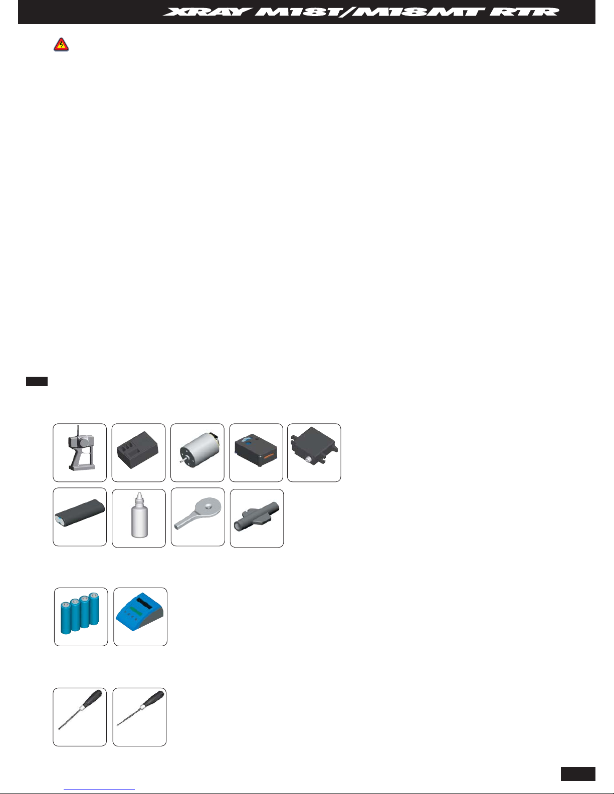
Supplied Equipment
Required Equipment
Required Tools
Transmitter Receiver Micro Speed Controller Micro Servo
Transmitter Batteries Battery Charger
Micro Motor
3.0mm Phillips Driver
(Hudy #163029)
Shock Oil
Micro Battery Pack
1.5mm Allen Wrench
(Hudy #111540)
Universal Tool
Pin Assembly Tool
Page 4
4
WARRANTY
A new, unused battery pack is
guaranteed against manufacturer’s
defects and workmanship. Any
damage due to misuse by the
user will be repaired at the user’s
expense. XRAY assumes no liability
for damages that arise from use or
misuse of the battery pack.
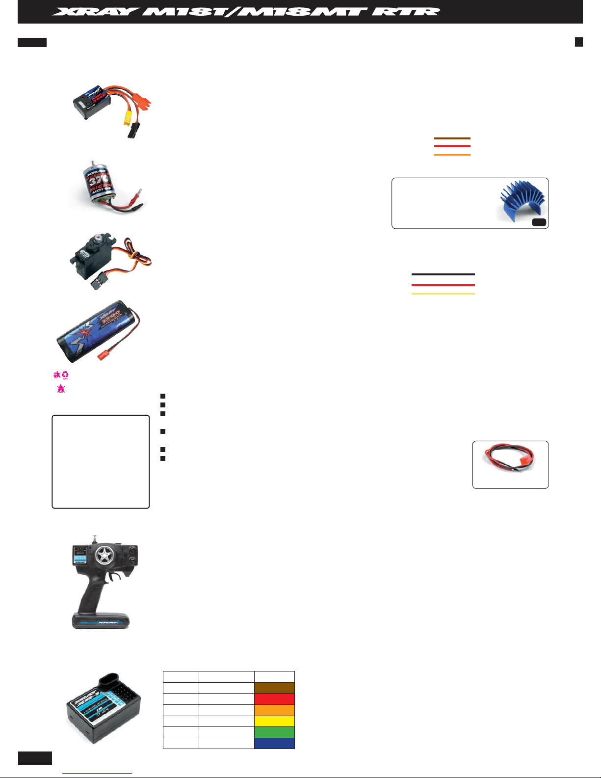
XMC 300R ELECTRONIC SPEED CONTROLLER
The XRAY XMC300R is an ESC (electronic speed controller) that has been specially designed for using up to a 370 Super
Size motor in the XRAY M18T/MT micro truck. Based on SMD technology, the result is a very small high-quality electronic
device. This forward-only ESC features proportional throttle/braking and battery elimination circuitry (BEC). An on-board
LED indicates the correct connection of ESC with the power supply, and proper operation (forward and brakes).
RECYCLE THE BATTERY PACK!
DO NOT DISPOSE OF IN FIRE!
XMS01MG MICRO SERVO
The high-quality metal-gear micro servo has been specially chosen for the M18T/MT because of its high precision, long
life and high quality.
370 SUPER SIZE MOTOR
The 370 Super Size motor provides ultra-high performance when used
with the included 6-cell micro battery pack. The motor includes an
integrated capacitor board so you do not need to solder any additional
capacitors.
MICRO BATTERY PACK
The 6-cell micro battery pack is designed to perfectly fit the M18T/MT, and is recommended for use only with the 370
Super Size motor and XMC300R ESC. The high-capacity NiMH 2/3A cells give excellent performance.
BATTERY MAINTENANCE
To achieve maximum performance of the batteries and ensure reliability, please follow these instructions:
CHARGING
We strongly recommend using a high-quality peak-detection charger with automatic shut-off.
The charger should be specifically designed for charging rechargeable nickel metal hydride (NiMH) cells.
For initial charging, set the charge current to 120 mA and charge for
14 hrs for 1200mAh battery pack or set the charge
current to 140 mA and charge for
14 hrs for 1400mAh battery pack.
For rapid charging, set the charge current to 1.2 maps (1200mAh) or to 1.4 maps (1400mAh). If rapid charging is
done at a higher current, the battery pack may generate too much heat and explode or vent.
Never leave the battery pack unattended while it is charging.
If the battery pack becomes too hot (113°F or higher), stop charging immediately.
Slow charge (initial 1200mAh): 120 mAh x 14 hours Rapid charge: 1.2 maps x 1 hour
Slow charge (initial 1400mAh): 140 mAh x 14 hours Rapid charge: 1.4 maps x 1 hour
DISCHARGING AND STORAGE
After use, we do not recommend discharging the pack completely, as this will damage the pack. You can safely recharge
the pack immediately after use without any performance degradation. If you will be storing the pack for longer than a
few days, partially discharging the pack down to approximately 40% capacity.
For charging use the included
#389130 charging cable
TIP
XT1 TRANSMITTER
• AM pistol grip transmitter
• Ergonomically designed steering wheel
• Digital proportional precise control
• Servo reversing
• Steering and throttle trims
• Throttle ATV / Adjustable Travel Volume
• Dual rate steering
• Adjustable neutral position for throttle trigger
• LED battery level indicator
Specifi cations
Frequency: 27MHz
Modulation AM: Pulse Proportional Modulation (PPM)
Transmitter batteries: AAx8 (UM-3x8)
Current Drain: 200mA@12V
Weight (w/o batteries): 394g
XR1 RECEIVER
This tiny 27MHz receiver has built-in BEC (Battery Eliminator Circuit). Interchangeable crystals in following range:
Specifi cations
Frequency Band: 27MHz
Channel: 2
BEC: Yes
Single Conversion: 455KHz
Channel Spacing: 10KHz
Dimensions: 37.7x25.6x15.3mm (length x width x height)
Weight: 15g
Channel Frequency (MHz) Flag Color
1 26.995 Brown
2 27.045 Red
3 27.095 Orange
4 27.145 Yellow
5 27.195
Green
6 27.255 Blue
INCLUDED IN THE KIT
Input Power: 4-6 cell battery NiMH or NiCD / 4.8V-7.2V
Min. Resistance : 0.032´/7.5V
Max. Resistance : 0.040´/6V
Continuous Current : max. 15A
Peak Current : max. 50A / 0.05 sec.
PWM Frequency : 900 Hz
BEC : 5V / 0.5A steady, 5V/1A short-timed
Temperature Range : 0-40 °C / 32-72°F
Wire Lead Colors:
Brown = ground
Red = power
Orange = signal
For cooler running and longer
motor life, use the machined
alu motor heatsink #382041
- for modified and super size
motors
Speed: 0.12 sec/60° transit
Torque: 32 oz. in.
Size: 30 x 12 x 30 mm
Weight: 22 g
Output gear: Metal
Black = ground
Red = power
Yellow = signal
Wire Lead Colors:
• Easy crystal access
• External charging jack for battery charging
• All SMT circuitry for dependability
Page 5

5
GETTING TO KNOW YOUR MICRO TRUCK
• Front bumper – protects the front end of the truck in the event of front collision
• Body posts – body posts support the body shell
• Body clip – small metal clips that go through the holes in the body posts, securing the body to the body posts
• Shock absorbers – coil-over shock absorbers provide smooth suspension movement when driving the truck through corners and going over bumps
• Shock springs – wound metal coil springs provide damping for the suspension when going over bumpers or around corners
• Front suspension arms – molded composite front suspension arms provide smooth suspension movement and suspension rigidity
• Front diff case – molded composite case that encloses the front gear differential
• Front differential (inside) – molded composite ball differential allows the front wheels to rotate at different speeds when turning a corner, just a like real truck
• Steering block – molded composite steering blocks support the front wheels and driveshafts, allowing smooth wheel rotation and left/right steering
• Chassis – molded composite main chassis plate provides a solid base for the other truck components to attach to
• Servo – high-quality XRAY servo provides smooth, fast steering control
• Receiver – high-quality XRAY radio receiver receives signals from transmitter and controls the attached motor speed controller and steering servo.
• Speed control – high-quality XRAY motor speed controller controls the operation of the motor
• Motor – high-quality XRAY 370 Super Size motor provides power to the truck’s wheels through the transmission
• Motor holder – molded composite motor holder secures the motor to the chassis and allows fi ne gear-mesh adjustment
• Battery pack – high-quality XRAY battery pack contains 6 individual cells connected in series, providing 7.2VV of power for your micro truck
• Battery brace – molded composite battery brace secure the battery pack to the chassis
• Spur gear – molded composite spur gear, driven by the motor, drives the truck’s transmission
• Main drive shaft – machined aluminum main drive shaft connects the front and rear transmissions, providing full-time 4WD power
• Rear diff case – molded composite case that encloses the rear gear differential
• Rear differential (inside) – molded composite ball differential allows the rear wheels to rotate at different speeds when turning a corner, just a like real truck
• Rear uprights – molded composite uprights support the rear wheels and driveshafts, allowing smooth wheel rotation
• Top deck – molded composite top deck for maximum stability
• Rear suspension arms – molded composite rear suspension arms provide smooth suspension movement and rigidity
Front
Bumper
Shock
Absorbers
Front
suspension
arms
Steering
Servo
Receiver
Chassis
Rear suspension
arms
Front
differential
(inside)
Front diff
case
Body
posts
Battery pack
Steering Rod
Speed Controller
Tires & Wheels
Shock
Absorbers
Rear
Shock
Tower
Rear Uprights
Top Deck
Motor
Steering Block
Motor
Holder
Battery Brace
Spur
Gear
• ELECTRIC MONSTER TRUCK
• LARGE CHEVRON PATTERN
• 8 SHOCKS
• MONSTER TRUCK BODY
• STADIUM ELECTRIC RACING TRUCK
• LOW PROFILE PIN TIRES
• 4 SHOCKS
• ANTI-ROLL BARS
• TRUCK BODY
M18MT Monster Truck shown (similar
components on M18T Truck)
Page 6
6
CHARGING BATTERIES
Before operating your micro truck for the fi rst time, you need to properly charge the receiver battery pack and the starterbox battery pack.
USE THE PROPER BATTERY CHARGER
We strongly recommend using a high-quality peak-detection charger with automatic shut-off. The charger should be specifi cally designed for charging NiMH batteries used
in the receiver pack and starterbox battery pack. Charge each pack at its recommended rate, and do not overcharge or damage or injury may result. Carefully follow the
manufacturer’s instructions that accompany the battery charger.
INITIAL CHARGING & CYCLING THE BATTERY PACKS
The receiver battery pack and starterbox battery pack must be cycled before fi rst-time use. When cycling the receiver battery pack for the fi rst time, carefully follow these instructions:
1. Set the charge current to 120 mA (0.12A) for 1200mAh battery pack or to 140 mA (0.14A) for 1400mAh battery pack.
2. Charge each battery pack for 14-16 hours. During charging it may happen that the charger will stop charging while the battery pack is not fully charged. In such case you
can continue charging until the battery pack is fully charged. This may happen one or more times during charging and this issue is related to the type of charger or type of
charging used.
3. After 14-16 hours disconnect the battery pack, even if the charger is still charging it.
4. Let the battery pack rest for 1 day.
5. After 1 day discharge the battery pack. Set the discharger to a 1.2A discharge rate for 1200mAh battery pack or to 1.4A discharge rate for 1400mAh battery pack, and set the
discharge cut-off voltage to 5.4V for the pack (0.9V per cell).
6. Let the battery pack rest for 6 hours.
Your battery packs have now been cycled and you can use them safely.
RAPID CHARGING
After you have initially charged and run the receiver and starterbox battery packs, you can rapid charge the packs afterwards.
Using a peak-detection charger, set each battery pack to charge at the proper rate (1.0A for receiver pack, X.XA for starterbox battery pack). Do not use higher charge currents;
rapid charging is done at a higher current, so the battery pack may generate too much heat and explode or vent. Never leave the battery pack unattended while it is charging. If
the battery pack becomes too hot (113°F or higher), stop charging immediately.
DISCHARGING AND STORAGE
After use, we DO NOT RECOMMEND discharging the packs completely, as this will damage the packs. You can safely recharge the packs immediately after use without any
performance degradation. If you will be storing the packs for longer than a month, partially discharge the pack down to approximately 40% capacity.
IMPORTANT WARNINGS
A new, unused battery pack is guaranteed against manufacturer‘s defects and workmanship. Any damage due to misuse by the user will be repaired at the user‘s expense.
There is no warranty expressed or implied that covers damage caused by normal use, or covers or implies how long the battery pack will run (run time), or last before requiring
replacement due to normal use and normal cell degradation. XRAY shall not be liable for any damage caused by overcharging, battery failure, improper charging or discharging,
use of non-approved chargers, use of non-approved batteries, and alternations or modifi cations of any kind to the charger, batteries, switches, or wiring.
WARRANTY
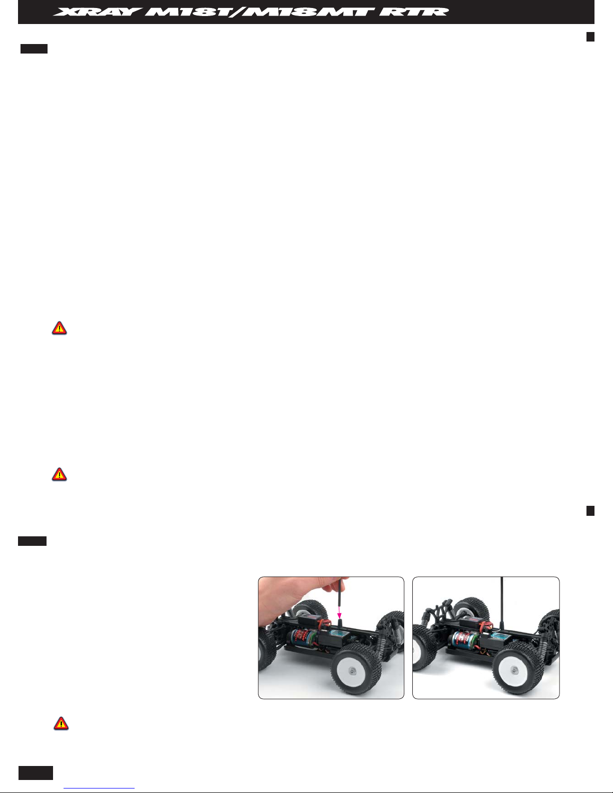
INSTALLING THE ANTENNA
You must install the antenna tube before operating your micro truck.
• Never disassemble the battery pack or peel away the cover.
• Keep the battery pack away from water.
• Do not touch the battery pack with wet hands or wet objects.
• Do not subject the battery pack to strong impacts and short circuits.
• Keep the battery pack away from fi re and fl ammable objects.
• Disconnect the battery pack when it is not in use.
• Do not put metal objects in the battery pack connector or touch the terminals
• in the connector.
• Do not throw away the battery pack when you no longer need it. Bring it to the shop from which you bought it, or to a shop offering battery recycling service.
• If leaked battery alkaline electrolyte gets in your eyes or on your skin, fl ush thoroughly with clean water and consult with a doctor immediately.
• Regularly check the wiring for damage. While running the truck, vibration or movement may cause damage to the wires which if left unchecked may result in a short circuit. If
any wire insulations becomes damaged, please dispose of the battery pack properly and do not use it, nor try to repair it.
• You are responsible for the proper use of this battery pack and any damage that may occur due to its use or misuse. XRAY is not liable for any injury, damage, or harm caused
to any person or property arising from the use or misuse of their products.
1. Locate the black antenna wire that exits the receiver. The receiver
is mounted on the top of the servo.
2. Pull the wire straight with your fi ngers and then insert the end of
the wire into one end of the antenna tube. Push the wire all the way
through the antenna tube.
3. Pull the remaining wire through the antenna tube, and then insert
the base of the antenna tube into the molded post on the chassis
to which the servo is mounted.
4. Fold the remaining antenna wire over the top of the tube. The
remaining wire can stick up.
TIP:
Spray a small amount of window cleaner on the antenna wire to
make it easier to push through the antenna tube.
Do not push the transmitter antenna down from the top. Pull it down
from the bottom, one segment at a time, to prevent binding and
kinking the antenna mast.
CAUTION !!!
Do not shorten the length of the antenna wire. Its length is tuned to the frequency band; cutting it may severely shorten the radio system’s range.
Page 7
7
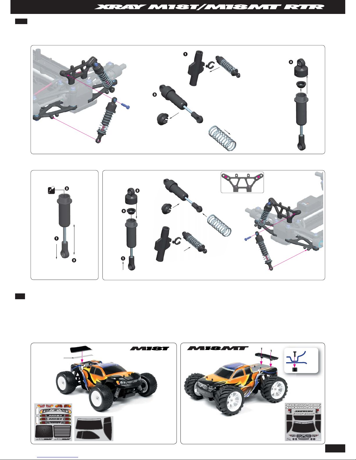
DECORATING THE BODY
The micro truck body was hand-painted with premium-quality, high-gloss paint and several stickers were applied to the body.
If you want to use the included rear wing, you must trim it fi rst. To install the wing on the M18MT Monster Truck make two holes in the rear of the body as indicated. Attach the
rear wing to the body using the included screws and plastic nuts. To install the wing on the M18T Truck use double-sided tape.
Extra decals are provided to decorate and personalize your micro truck body.
Use the tip of a hobby knife to lift the corner of a decal, then remove it from the backing sheet.
Position the decal over the desired location on the body, and press it onto the body. Pull tight on the decal if required, and use your fi ngers to smooth out any air bubbles.
Decals for M18T
Decals for M18MT
FILLING AND INSTALLING THE SHOCK ABSORBERS
Remove each shock absorber, fi ll each shock absorber with the supplied shock oil, and re-install on the micro truck.
REMOVING THE SHOCKS
FILLING THE SHOCKS INSTALLING THE SHOCKS
Thread the shock cap onto the shock body.
Excess oil should spill out.
Fill until shock oil nearly overfl ows
Gently move the piston up and
down to get rid of air bubbles
Pull down
the piston
OIL
TEAMXRAY
Remove clips
Remove shock collar and
spring from each shock (front
and rear)
Remove all shocks
(front and rear)
Unthread the shock cap from
the shock body and remove
the shock membrane.
Pull down
the piston
Insert clips according
to track conditions
INITIAL POSITIONS
RE-INSTALL ALL SHOCKS
(front and rear)
Double side tape
Wing
Body
Note how the shocks are attached
(especially on M18MT Monster Truck).
Page 8
8
BATTERY PACK
STEERING
SERVO
ANTENNA WIRE
RECEIVER
RECEIVER
SPEEDSPEED
CONTROLCONTROL
MOTORMOTOR
RECEIVER
1 CH
2 CH
SPEED
CONTROL
MOTOR
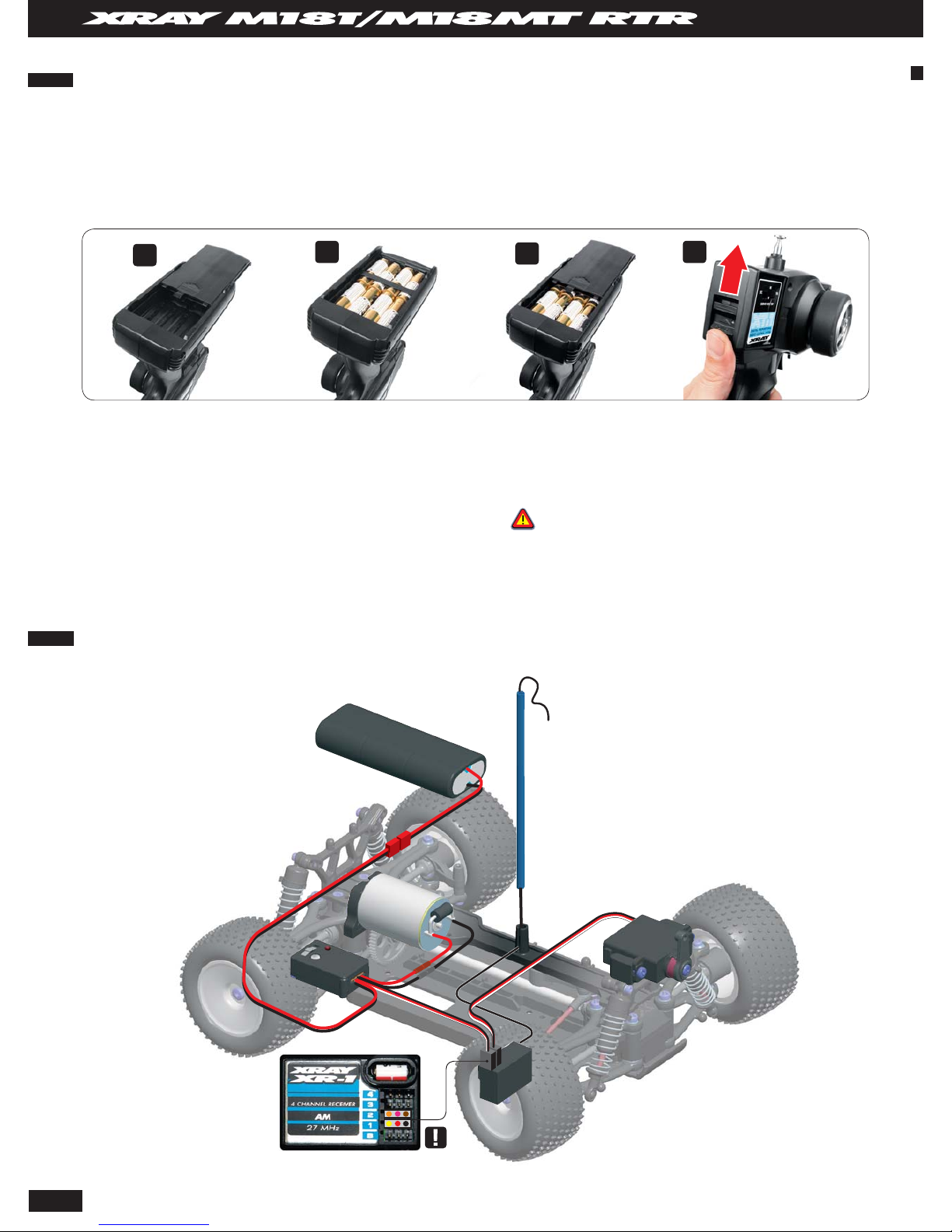
INSTALLING THE TRANSMITTER BATTERIES
Your XT1 Transmitter uses eight AA batteries. The battery tray is located at the base of the transmitter.
1. Remove the battery cover (bottom of transmitter) and remove the battery tray.
2. Install eight (8) AA alkaline batteries into the battery holder. Pay close attention to the correct direction of the positive (+) and negative (-) ends of the
batteries as marked in the tray.
3. Reinstall the battery tray using the molded pegs in the bottom as a guide, then replace the battery cover.
4. Turn on the transmitter and check that the LED power indicator gives a solid red light.
If the power indicator does not light up, the transmitter batteries may be weak, discharged, or possibly installed incorrectly. Check the battery positions fi rst, then replace any weak
batteries with new or freshly-charged batteries as required.
The power indicator light does not indicate the charge level of the main battery pack in the truck.
Use only fresh alkaline or rechargeable batteries, all of the same brand. Make sure that rechargeable batteries are fully charged according to the manufacturer’s instructions. If
you use rechargeable batteries in your transmitter, be aware that when they begin to lose their charge, they lose power much more quickly than regular alkaline batteries.
1.
1
1.
2
1.
3
1.
4
CAUTION !
Stop running your micro truck at the fi rst sign of weak batteries to avoid losing
control.
TIP: Transmitter Battery Holder
Make sure that the contacts in the battery holder stay clean by using a pencil eraser to
gently remove any corrosion or dirt that may accumulate on them. It is recommended to
do this each time you install fresh cells into your transmitter.
When the transmitter will not be used for any short or long period of time, always remove the batteries. If the batteries are loaded incorrectly, the transmitter may be damaged.
ELECTRONICS ASSEMBLY AND WIRING CONNECTION
NOTE
ORIENTATION
Page 9

9
XT1 TRANSMITTER CONTROLS
Transmitter Antenna
Transmits the radio signal from the transmitter. Always extend the
transmitter antenna before you operate the transmitter; otherwise you
risk create interference to another modeller.
Transmitter Crystal
Solid-state plug-in crystal allows you to change the frequency on which
your transmitter broadcasts. The receiver must contain the matching
frequency crystal.
Steering Trim
Adjusts the steering left/right in small increments so the model runs
straight when the transmitter steering wheel is at rest (centered).
Throttle Trim
Adjusts the throttle neutral position up/down in small increments so
the truck does not move when the transmitter throttle trigger is at rest
(neutral)
Throttle Trigger
Controls the movement of the truck. Truck moves forward when you
pull the throttle trigger, and brake is applied when you push the throttle
trigger.
Steering Wheel
Controls the left/right steering of the truck.
XRAY RADIO SYSTEM
Power Switch
Turns the transmitter on or off.
Steering D/R (Dual Rate)
Adjusts the steering sensitivity.
External Charging Jack
Recharges the transmitter battery if you are using a rechargeable battery
pack.
Steering Reverse
Changes the direction of the truck’s steering in relation to the way you
turn the transmitter steering wheel. Always be sure the steering reverse is
in the “R“ position.
Throttle Reverse
Changes the truck’s forward/reverse direction in relation to the way you
move the transmitter throttle trigger. Always be sure the throttle reverse is
in the “N“ position.
Battery Cover
Covers the transmitter battery compartment
Battery Indicator
LED indicates the transmitter battery voltage level. If the Red LED does not
light up, please replace the transmitter batteries (8x AA batteries).
Transmitter Antenna
Steering Wheel
Transmitter Crystal
Steering Trim
Steering D/R (Dual Rate)
Throttle Trim
Throttle Trigger
Battery Cover
Power Switch
Steering Reverse
Throttle Reverse
Battery Indicator
External Charging Jack
Page 10

10
RADIO SYSTEM TERMINOLOGY
Take some time to familiarize yourself with these radio system terms that are
used throughout this manual.
BEC (Battery Eliminator Circuitry)
BEC circuitry powers the receiver and steering servo from the main battery
pack. This eliminates the need for using a separate receiver battery pack to
power the radio equipment on the truck.
Channel
The 27 MHz frequency band is divided into 6 channels so that up to 6 models
can be operated simultaneously. Each channel is referred to by its fl ag color
and channel number according to the following table.
Channel Frequency (MHz) Flag Color
1 26.995 Brown
2 27.045 Red
3 27.095 Orange
4 27.145 Yellow
5 27.195 Green
6 27.255 Blue
Clearing your Frequency
A routine, verbal check to make sure nobody else in your area is operating on
the same channel. Always clear your frequency by calling out your channel
number before operating your model. If the channel is already in use, wait
until it is clear to use.
Crystal
The small, plug-in solid state in device that sets the operating frequency
(channel) on which the radio system will operate. For each channel there
are two crystals: one for the transmitter and one for the receiver. Each crystal
should be marked with either Tx (transmitter) or Rx (receiver).
It is recommended that you use only authentic XRAY crystal sets, and to
change both the transmitter and receiver crystal at the same time.
Switch
The mechanical on/off switch that controls the power to the onboard
electronics.
Frequency Band
The radio frequency band used by the transmitter to send signals to your
truck. Your radio system operates on the 27 MHz frequency band.
Neutral Position
The positions that the steering servo and throttle servo go to when the
transmitter controls are at their neutral settings.
NiMH
Refers to rechargeable, nickel-metal hydride (NiMH) batteries.
Receiver
The radio receiver inside your truck that receives signals from the transmitter
and relays them to the steering servo and throttle servo.
Servo
Small electronic motor unit in your truck that operates the steering
mechanism or throttle/brake mechanism.
Transmitter
The hand-held radio unit that sends throttle and steering signals to your truck.
Trim
The fi ne-tuning adjustment for the neutral position of the steering servo
and throttle servo, made by turning small knobs on the transmitter.
Always turn on the transmitter fi rst by sliding the power switch to the ON
position. The red light should go on. If the red light does not go on, check
for incorrectly installed batteries or weak batteries.
1. Turn on the Transmitter
2. Turn on the Truck
USING THE RADIO SYSTEM
Now that everything is prepared for operating the micro truck, please follow these instructions.
Radio System Rules
• Each time you prepare to run your micro truck, you must clear your frequency to be sure no one else in the area is using the same channel as you.
• There are six possible channels, numbered #1 through #6. Each is represented by a color. Look at the crystal plugged into the back of your transmitter
to determine which channel your micro truck is assigned to.
• Always turn your transmitter on fi rst and off last. This will help to prevent your micro truck from receiving stray signals from another transmitter or
other source, and running out of control.
• Always have the transmitter turned on before you plug in the battery pack in the model (having the switch in ON position).
• Always use new or freshly charged batteries for the radio system. Weak batteries will limit the range of the radio signal between the receiver and the
transmitter. Loss of the radio signal can cause you to lose control of your micro truck.
After the transmitter is on, turn the ESC power switch to the ON position.
The electronics should activate. Check the radio range by walking away
from the car.
Page 11

11
1.
1
Turn the transmitter steering wheel left then right to
check if the front wheels move correctly. The amount
of steering varies according to the steering wheel
movement. If the steering wheel is turned all the way
left or right, the front wheels will also steer all the way
right or left.
Operate the throttle trigger to check if the truck goes
forward and backwards.
Pull the trigger backward to make the truck move
forward; push the trigger forward to apply the
brakes.
The amount of acceleration varies according to the
throttle trigger movement. If the throttle trigger is
pulled all the way back, the faster the truck will run.
4. Check the Driving Operation
Use the steering trim knob on the transmitter to fi netune the steering position if the truck does not drive
straight with the steering wheel in the neutral position
(centered).
5. Adjust the Steering Trim (optional)
Use the throttle trim knob on the transmitter to fi netune the throttle neutral position if the truck wheels
are rotating with the throttle trigger in the neutral
position.
7. Adjust the Throttle Trim (optional)
8. When Turning the Vehicle OFF
NEUTRAL
RIGHT
LEFT
NEUTRAL NEUTRAL
NEUTRAL
FORWARD
BRAKE
1.
2
Steering Dual Rate is used to adjust the amount of
steering servo movement.
6. Steering Dual Rate
ST. TRIM
LEFT
RIGHT
DUAL RATE
TH. TRIM
LEFT
RIGHT
Always be sure the servo-reversing
switch (TH.REV) is in the 'N' position
Always be sure the servo-reversing
switch (ST.REV) is in the 'N' position
BRAKE
NEUTRAL
FORWARD
RIGHTLEFT RIGHTLEFT
3. Check the Steering Operation
Turn off the car’s ESC fi rst. After the ESC is turned off, turn off the
transmitter.
Page 12

12
TESTING THE RANGE OF THE RADIO SYSTEM
It is important to test the range of the radio system before driving the micro truck. This will let you know if there is any interference in the signal between
your transmitter and the truck, or if the batteries are low. It is best to perform a range test with 2 people.
1. Make sure that the transmitter batteries and receiver pack batteries are fully charged.
2. Turn on the transmitter, and then turn on the ESC.
3. Have someone hold the truck while it is running. Make sure s/he holds it safely.
4. While near to the truck, operate the throttle/brake and steering controls.
5. Walk away from the person holding the truck, and continue to operate the controls. The truck should respond to your transmitter without glitching.
6. Continue to walk away, still operating the transmitter controls, until the truck stops responding to your transmitter or it starts behaving erratically
(glitching).
7. Walk back towards the person holding the truck until the truck again responds properly to your transmitter. THIS IS THE MAXIMUM SAFE RANGE OF
THE RADIO SYSTEM.
8. Turn off the ESC, and then turn off the transmitter.
To tighten the front differential you need to remove the RIGHT front upper arm to give
access into the diff for adjustment with the included Phillips screwdriver. Insert the
screwdriver tip into the differential adjustment screw, hold the left front wheel fi rmly and
then tighten (CW) the screw as required.
Please note that the factory pre-assembled ball differential is pre-built but is NOT tightened. To enjoy long life and smooth performance of the differential, you need to break in
both front and rear differentials properly. You will need to run the truck several times for a short time, and each time tighten both differentials a small amount.
DIFFERENTIAL SETTING
To tighten the differentials, remove the front/rear upper arms as described below, and use a Phillips screwdriver to tighten the diff adjustment screw.
BREAK-IN PROCEDURE
1. Run the truck for the fi rst time at only ¼ throttle for 30-60 seconds.
2. Tighten both front and rear diffs slightly by 1/16 turn.
3. Run the truck again for 2 minutes at ¼ throttle.
4. Tighten both front and rear diffs slightly by 1/16 turn. The differential should still turn freely.
5. Run the truck again for 5 minutes, this time up to ½ throttle.
6. Again tighten both front and rear diffs by 1/16 turn.
Now the differential should be tight enough. The differentials should still turn freely but must still slip slightly with higher resistance.
To tighten the rear differential you need to remove the LEFT rear upper arm to give
access into the diff for adjustment with the included Phillips screwdriver. Insert the
screwdriver tip into the differential adjustment screw, hold the right rear wheel fi rmly
and then tighten (CW) the screw as required.
HOLD TIRE
HOLD TIRE
Remove the screw from the top of the RIGHT front steering block or LEFT rear upright. After removing the screw, lift the upper arm to allow the drive shaft to disconnect from
the differential. You can now fi t the screwdriver into the ball diff.
TIGHTENING FRONT DIFF TIGHTENING REAR DIFF
REMOVING SCREW
REMOVING UPPER ARM
BREAKING IN THE BALL DIFFERENTIALS
Page 13

13
To check the slip of the front differential, grab the RIGHT front wheel and hold the
spur gear. Turn the left front wheel. You should be able to turn the wheel but with
resistance.
To check the slip of the rear differential, grab the RIGHT rear wheel and hold the
spur gear. Turn the left rear wheel. You should be able to turn the wheel but with
resistance.
BREAK-IN PROCEDURE QUICK TABLE
Run Run-time Throttle applied After run tighten diff by
1st 30~60sec. ¼ throttle 1/16 turn (CW)
2nd 2 min ¼ throttle 1/16 turn (CW)
3rd 3 min ½ throttle 1/16 turn (CW)
HOLD TIRE
HOLD SPUR GEAR
TURN WHEEL TO
CHECK SLIP
TURN WHEEL TO
CHECK SLIP
HOLD TIRE
CHECKING FRONT DIFF SLIP CHECKING REAR DIFF SLIP
HOLD SPUR GEAR
DRIVING THE MICRO TRUCK
After you have familiarized yourself with the controls and broken in the ball differentials, it’s time to drive your micro truck and have some fun!
Here are some things to keep in mind when driving your micro truck:
• DO NOT run the truck in or through water, snow, or mud. Even small amounts of water can cause electronics failure and loss of control.
• Avoid excessive high-speed operation running for long periods of time or long distances.
• Do not drive the truck with any kind of damage, especially drivetrain damage. This may cause motor damage from overloads due to drivetrain drag or friction, or over-
revving due to loose or missing parts.
• Do not use your truck to tow anything behind it; towing puts a high load on the motor.
• If your truck gets stuck, stop immediately! Move the truck and then continue driving.
• NEVER turn off the radio system while the truck is on, as this could cause the truck to go out of control.
ADJUSTING THE MICRO TRUCK
GEARING
FRONT TOE
Adjust front toe by adjusting the length of the left and right steering rods.
Steering rod length Characteristics
More front toe-in =
longer steering rod
· increases straight-line stability
· decreases steering response
· increases steering mid-corner and on-power corner exit
More front toe-out =
shorter steering rod
· decreases straight-line stability
· increases initial steering response
· decreases steering on-power at corner exit
To change pinion gears, first remove your motor along with the old pinion gear. Install the new pinion gear and re-install your motor. When installing the two 2x8mm button head
screws to secure the motor mount to the chassis, do not fully tighten them. Leave them just loose enough so you can slide the motor in and out towards the spur gear. Make sure
there is sufficient space between spur gear and pinion to allow for a small amount of backlash so the gears do not bind, see the diagram. When you have the motor in this position,
you may then fully tighten the motor mount screws. Always check the gear mesh one more time to confirm that the motor did not move when tightening the screws.
PINION GEA
R
SPUR GEAR
SPUR
GEAR
PINION
GEAR
FINAL
RATIO
ACCELERATION
SPEED
09
10
11
12
13
14
M18MT
*
*
*
*
M18T
54
x
x
x
x
o
o
x - INCLUDED WITH KIT
o - AVAILABLE OPTION
- INCLUDED IN M18MT
- INCLUDED IN M18T
15.00
13.50
12.27
11.25
10.38
09.64
INTERNAL RATIO 1:2.5
THE MOTOR STAND IS ADJUSTABLE:
1. Release screws from the bottom of chassis.
2. Move the motor stand as needed.
3. Tighten the screws.
TECH TIP
FRONT TOE
IN
OUT
Page 14

14
For adjusting the rear toe-in you have to purchase the #383302 adjustable turnbuckle set.
Adjust rear toe-in by changing the length of the rear turnbuckles. Shortening the turnbuckle gives MORE rear toe-in; lengthening the turnbuckles give LESS
rear toe-in.
Make sure both rods are adjusted to the same length, and NEVER use toe-out on the rear wheels (always use toe-in).
Rear toe-in angle Characteristics
More rear toe-in · increases stability under braking
· increases stability on power at corner exit
· decreases top speed
· if too much rear toe-in is used, the truck will be
twitchy to drive and harder to recover if it loses
traction
Less rear toe-in · increases steering
· decreases stability on power at corner exit
· increases top speed
· if the truck slides, it will be much easier to
control
REAR TOE IN
You can use shock oils of different weights in a shock absorber.
Shock Oil Characteristics
Thinner · same characteristics as larger pistons holes
Thicker · same characteristics as smaller pistons holes
Silicone Shock Oil
Note that typically you should use piston hole sizes to suit the track conditions rather than
alter the oil viscosity.
Use only the genuine premium
quality silicone shock oils.
The shock oils are availabe
in 50ml size in these
viscosities:
SHOCK OIL
For each type of shock piston (conical or straight holes), there are three pistons with holes of
different sizes.
Piston hole size Characteristics
2 holes · harder damping
· slower chassis weight transfer
· slower response
· decreases chance of bottoming out when landing if used with “thicker” oil
· decreases chassis roll if used with “thicker” oil
· use with thinner oil if track is rough
4 holes · softer damping
· increases traction
· quicker chassis weight transfer
· quicker response
· increases chance of bottoming out when landing if used with “thinner” oil
· increases chassis roll if used with “thinner” oils
· use with thicker oil if track is smooth
PISTON HOLE SIZE
You can use shock springs of different rates to alter performance.
Shock spring Characteristics
Softer · more chassis roll
· more traction
· better on bumpy tracks
· increases chance of bottoming out when landing
Stiffer · less chassis roll
· less traction
· more responsive
· better on smooth tracks
· decreases chance of bottoming out when landing
SHOCK SPRINGS
You can use shock springs of different rates to alter performance.
388181 XRAY Spring Front + Rear (4+4) - Set M18MT - SOFT
388191 XRAY Spring Front + Rear - Set M18T - SOFT-MEDIUM
388192 XRAY Spring Front + Rear - Set - MEDIUM
Part Viscosity Part Viscosity
359225 250 cSt 359260 600 cSt
359230 300 cSt 359270 700 cSt
359235 350 cSt 359280 800 cSt
359240 400 cSt 359290 900 cSt
359245 450 cSt 359301 1000 cSt
359250 500 cSt 359302 2000 cSt
REAR TOE
OUT
IN
Page 15

15
SHOCK MOUNTING POSITION
You can change the shock mounting position by leaning the shocks at different angles, and also moving the shock closer or further from the centerline of the truck. You accomplish
this by moving the shock top and bottom mounts to different locations on the shock towers and lower arms
Shock position Characteristics
More inclined =
moving in on tower and/or
moving out on lower arm
· softer initial damping
· more progressive damping
· more lateral (side) traction
· makes the handling more ”forgiving”
· may be better on high-bite tracks, since it slows down
the handling and makes it easier to driver
Less inclined =
moving out on tower and/or
moving in on lower arm
· harder damping
· less lateral (side) traction
· makes the truck more responsive
· usually better suited on technical tracks
UPPER SHOCK POSITION
LOWER SHOCK POSITION
21
1
2
1
2
3
1
2
3
SHOCK PRELOAD
Adjust the front/rear shock spring preload by using preload clips of various thicknesses above the shock springs.
IMPORTANT!
Make equal adjustments on both left and right sides of the truck.
Shock preload Characteristics
Less preload =
thinner/less spacers
· lower ride height
· may give higher corner speed on high bite tracks
· better suited to smooth tracks
More preload =
thicker/more
spacers
· higher ride height
· less prone to bottoming out
· better suited to rough tracks
Adjust the stiffness of the front or rear anti-roll bar by using a thinner or thicker wire.
Anti-roll bar stiffness Front/Rear Characteristics
Softer = thinner wire Front · increases front chassis roll
· increases front traction
· decreases rear traction
· increases off-power steering (may cause oversteer)
Rear · increases rear chassis roll
· increases rear traction
· decreases front traction
· decreases on-power steering (increases understeer)
Stiffer = thicker wire Front · decreases front chassis roll
· decreases front traction
· decreases off-power steering at corner entry (increases
understeer)
· quicker steering response
Rear · decreases rear chassis roll
· decreases rear traction
· increases front traction
· increases on-power steering (may cause oversteer)
· quicker steering response in high speed chicanes
ANTI-ROLL BARS
Anti-roll bars are used only on micro truck. Anti-roll bars are not used on micro monster truck.
Page 16

16
MAINTAINING YOUR M18T/MT MICRO TRUCK
Your M18T/MT is designed to be easy to work on, and should require very little maintenance to keep it at its peak performance. To keep your micro truck running at optimal
performance, you should periodically perform maintenance on the truck.
General Truck Maintenance
• Make sure all fasteners are properly tightened. Check them periodically.
• Make sure that chassis screws do not protrude from the chassis.
• For the best performance, it is very important that great care is taken to ensure the free movement of all parts.
• Clean all ball-bearings so they move very easily and freely.
• Tap or pre-thread the plastic parts when threading screws.
• Self-tapping screws cut threads into the parts when being tightened. Do not use excessive force when tightening the self-tapping screws because you may strip out the thread
in the plastic. We recommended you stop tightening a screw when you feel some resistance.
• Ask your local hobby shop for any advice. Please support your local hobby shop. We at XRAY Model Racing Cars support all local hobby dealers. Therefore we ask you, if
at all possible, to purchase XRAY products at your hobby dealer and give them your support like we do. If you have difficulty finding XRAY products, please check out www.
teamxray.com to get advice, or contact us via e-mail at info@teamxray.com, or contact the XRAY distributor in your country.
Battery Maintenance
The M18T/MT’s main battery pack is made of high-quality NiMH cells, and may be recharged up to 1000 times. We strongly recommend using a highquality peak-detection charger that is suitable for use with NiMH batteries. Using an inferior-quality charger may result in damage to the battery pack and
risk of injury or fi re.
The transmitter uses eight AA cells. When the batteries get weak, replace them with high-quality alkaline batteries or rechargeable batteries.
Motor Maintenance
The XRAY 370 Super Size motor is a high-performance, sealed, non-rebuildable motor. Keep the motor clean from debris by brushing it off or using
compressed air. Do not attempt to open the motor; this will render the motor inoperable. Periodically put a drop of light oil in the bushing around the output
shaft. Be careful not to overheat the motor or its performance may suffer.
Electronics Maintenance
The electronic components installed on the M18T/MT should not require any maintenance. Use a soft brush to remove any dust or debris that may
accumulate on or around the car’s components. Do not use solvents to clean the electronics of the M18T/MT.
Tire Replacement
The stock rubber tires are designed for long life and high grip. Over time and a lot of usage you may notice the tires wearing in strange patterns. If this
happens, we advise you to replace the tires with new ones. Glue a new set of tires to a new set of white rims, and install them in place of the old tires.
Bearing Maintenance
The M18T/MT contains 16 high-speed, high-quality sealed ball-bearings. We recommend that you periodically clean the bearings (using motor cleaner)
and apply a drop of light oil to ensure longevity and smoothness.
To clean and oil the bearings, you must disassemble the car and remove the bearings. Spray out the bearings using motor spray so all external and internal
debris is removed. Then apply a drop of light oil to the inside of the bearing. Reinstall the bearings.
Body Maintenance
The tough Lexan® body on the M18T/MT is designed to withstand the rigors of racing. Use a soft brush to remove dirt/dust after every run.
If your micro truck is performing less than optimally or is having problems, use the following troubleshooting information to attempt to determine the origin of the issue and
possible solutions. We also recommend consulting with your local hobby dealer if you encounter problems.
SERVO T ROUBLESHOOTING
Servo makes a grinding noise or
acts erratic
Remove the servo from the truck.
Open the case and remove the gears. Examine them for broken teeth. If broken, replace with a new gear set.
Servo jitters
Remove the servo from the truck.
Open the case and remove the gears.
Spray a zero-residue electrical cleaner into and around the potentiometer and work it in.
After the cleaner has dried, re-install the gears and close the case.
Possible damaged receiver/transmitter crystal.
Servo doesn’t center properly
Disconnect the steering rod from the left front steeringblock. Steer left and right with the transmitter several times. If the servo arm does not return to the
same neutral position each time, the servo may be damaged.
Remove the servo from the truck. Open the case and check for proper gear alignment. Next check the case top for wear. If wear is evident, replace the case.
Servo is locked in place
Remove the servo from the truck.
Open the case and check for proper gear alignment. If gears are damaged, replace the gear seta
Check the case top for wear. If wear is evident, replace the case.
Servo hums
This is normal if the servo is trying to hold position against the force of a load.
If the servo hums when no load is applied, try loosening the servo case screws 1/4 to 1/2 turn.
Servo gets hot
Check the servo wiring, it should match the receiver being used.
If the wiring is okay, the servo motor may be stalled due to a failed gear train. Remove the servo from the truck, open the case and inspect for any damage.
Wheels turn in opposite direction to
setting input
Change the servo reversing setting, and then re-adjust the steering subtrim and EPA settings.
Page 17

17
Please note that the #389170 XMS01MG XRAY Micro Servo is an analog servo and therefore it is required and necessary that you set your radio transmitter
to Standard Response Mode, not High Response Mode. If you set your radio to High Response Mode (or similar), you run the risk that the servo electronics
will become damaged, possibly resulting in servo failure. For more information about setting up your radio, please see the instruction manual supplied with
the radio.
Some servos may get into contact with the central
aluminum layshaft and this can brake the free action
of the transmission. It is suggested to slightly modify the
servo holder.
Use a sharp hobby knife and remove the edge of the
servo holder as shown.
CUT
Safety Precautions:
• Practice using the hobby knife before making this modifi cation.
• Wear safety glasses and gloves.
• Perform this modifi cation in a safe area away from small children.
View of the finished modification
TECH TIP: MODIFICATION OF SERVO HOLDERS
IMPORTANT WARNING
XMC300R ELECTRONIC SPEED CONTROLLER TROUBLESHOOTING
The XRAY XMC300R is bi-directional ESC (electronic speed controller) with electronic brake and reverse suggested for use with 180,
280, 300, and 370 “micro“ motors; it will fi t 1/18, 1/20, and 1/24 micro cars.
SPECIFICATIONS
• operated by microprocessor, fully digital controller
• bi-directional ESC for use with up to 370-size motors
• smooth linear regulation of drive from 0% to 100%
• installed electronic brake 100%
• brake responds only after switching from the forward movement to the
reverse movement, braking time is 0.1 sec, after end of braking the ESC will
automatically switch to reverse
• battery elimination circuitry (BEC)
XMC300R TECHNICAL DATA
Input Power: ................... 4-6 cell battery NiMH or NiCD / 4.8V-7.2V
Min. Resistance: ....................................................... 0.032 Ω / 7.5V
Max. Resistance: ......................................................... 0.040 Ω / 6V
Continuous Current: .........................................................max. 15A
Peak Current: ..................................................max. 50A / 0.05 sec.
PWM Frequency: .................................................................. 900 Hz
BEC: ...................................... 5V / 0.5A steady, 5V / 1A short-timed
Temperature Range: .............................................. 0-40°C / 32-72°F
Dimensions: ...............30x19.5x10.5mm / 1.180“ x 0.768“ x 0.413“
WARNING!
•This product is not suitable for children except under the direct supervision of an adult.
• First-time users should seek advice from people who have experience with RC cars and who have properly installed and used electronic speed
controllers.
• Never leave your model unattended with the battery connected.
• Be sure that your operating frequency is clear before turning on or running your model, and never share the same frequency with somebody else at the
same time. Ensure that others are aware of the operating frequency you are using and when you are using it.
• Always turn on your transmitter before you turn on the ESC or connect the battery pack. Always turn off the ESC or disconnect the battery pack before
turning off your transmitter.
• Immediately after using your model, do NOT touch the model’s electronic equipment, as it may be hot.
• When you connect the battery and turn on the electronics, make sure your car is physically prevented from moving or getting away from you and causing
damage.
• Technical faults of mechanical or electrical nature may cause the motor to jump into motion unexpectedly, which can cause serious damage or injury.
• All cables and connectors must be effectively insulated. Short circuits can ruin your ESC, servo, or battery pack.
• Use only polarized connectors for ESC connections.
• Do not reverse the polarity of the ESC connections.
• If a fault should occur, this could cause a fi re in the model and threaten anything in the vicinity.
• Do not allow any metal part to short circuit the batteries, ESC, or other electrical/electronic device on the model.
• The ESC is designed exclusively for use in battery-operated radio-controlled models. No other usage is permissible.
• Like all electronic components, the ESC must not be exposed to water or fi re.
• Do not stall the motor. The ESC will fail within seconds if power is applied to the motor when the car cannot move.
• When the motor is connected to the ESC, do not connect a separate battery to the motor to run it. This will damage the ESC and invalidate the
warranty.
• This speed controller is NOT waterproof.
• Always make sure that enough air can get to the speed controller so that good cooling conditions are achieved.
Page 18

18
NEVER
• This ESC is designed to use with micro stock motors and micro motors up to 370 Super Size motors. Never use this ESC with motors larger than 370 as
you will ruin the ESC.
• Never use this ESC with brushless motors.
• Never run your model car in water, snow or wet conditions. This could result in an electronic device shorting out and causing a fi re.
• Avoid incorrect connections. Reverse polarity will damage the ESC and void your warranty.
• Do not let output tabs (where wires connect to ESC) touch any other surface. Never touch the output tabs with any metal parts or conducting material. This
may short your ESC and void your warranty.
• Do not attach a Schottky diode to your ESC or motor. This will ruin the forward/reverse ESC and void your warranty.
• Do not modify any parts of the ESC and especially do not modify or change any of the wires otherwise you void warranty.
• Never leave your model car unattended when the battery is connected. If a fault should occur the result could be a fi re in the model which could destroy
anything else in the vicinity and injury persons.
• Never wrap your ESC in foil or fi lm; air must always be able to fl ow round and over the unit.
• Never change the polarity of the receiver plug.
• Never use water or chemicals to clean the ESC.
• Never expose the ESC to extreme heat or cold temperatures.
• Never touch the ESC and any of its parts after a run. It could be very hot and injure you.
• Never dry the ESC in a microwave oven.
CONNECTIONS
The ESC is connected to various components:
MOTOR – red and black wire with female plug,
RECEIVER - black connector
BATTERY PACK - red connector.
The battery used may be 4.8V (4-cell), 6V (5-cell), or 7.2V (6-cell).
receiver
battery pack
Motor Motor +
switch
LED DIODE
SET-UP BUTTON
SPEED CONTROLLER LED INDICATION
INSTALLATION
Follow these steps after you have installed the ESC in your car:
1. Make sure the white switch on the ESC case is in the OFF position.
2. Connect the ESC to the receiver‘s Channel 2 slot.
3. Connect the ESC to the motor: red wire to positive (+) red male wire on the motor,
black wire to negative (-) black male wire on the motor.
4. Check all wiring and connections before you connect the ESC to a drive battery.
Extremely important: incorrect polarity will damage the speed controller.
5. Connect the red connector of the speed controller to the battery pack.
The ESC is now ready for set-up.
The LED diode is used for indication of the drive direction.
Neutral
steady light
Partial Throttle
double-fl ash (repeats)
Full Throttle
steady light
Brake
fl ash (repeats)
Reverse
triple-fl ash (repeats)
SCHOTTKY DIODE
Do NOT use the Schottky diode on the motor when using XMC300R speed controller.
The Schottky diode can be used only with pure forward/brake speed controllers. Using Schottky diode on your motor when using XMC300R speed controller will
destroy the ESC and thus will void the warranty immediately.
INSTALLATION TIPS:
• Mount the ESC in the model car using a double-sided foam tape.
• When installing the ESC in an XRAY model racing car use the supplied screws to install it in the designed location.
• Provide plenty of cooling openings in the car body; this increases the performance and extends the life of electronic components.
• Install the ESC in a location where it is protected from crash damage.
• The ESC should be installed in such a way that you have easy access to the buttons.
• Ensure that there is an adequate distance (at least 3cm) between the ESC and power cables and the receiver or receiver aerial. Avoid direct contact
between all power system components and the receiver or aerial, as this can cause interference. If you encounter interference problems, reposition the
components in the model.
• The aerial should be run vertically up and away from the receiver. Avoid contact with any parts made of carbon fi ber or metal. If the aerial is too long,
don’t coil up the excess length. Make sure to read and understand the instructions supplied with your radio control system.
Page 19

19
If you transmitter does not feature these set-up functions, it is already in “basic set-up“ mode.
• Ensure that the ESC is not connected to the drive battery, and is switched off.
• Remove the motor pinion, or ensure in some other way that the wheels of the model are free to rotate.
• Switch the transmitter on.
• Set the transmitter throttle to neutral.
• Connect the ESC to the battery.
• Hold the Set-up button pressed and at the same time switch on the speed controller (white switch to the ON position).
• After the LED fl ashes once shortly, the speed controller is ready for Neutral position set-up.
Neutral position set-up
• Leave the throttle at neutral, and press the Set-up button for 1 sec.
• After the LED fl ashes two times shortly the neutral setting is stored and you can release the Set-up button.
Full throttle set-up
• Hold the transmitter at full throttle, and press the Set-up button for 1 sec.
• After the LED fl ashes three times shortly the full-throttle setting is stored and you can release the Set-up button.
Brake set-up
• Hold the transmitter at full brake, and press the Set-up button for 1 sec.
• After the LED fl ashes once-long the brake setting is stored and you can release the Set-up button.
Set-up fi nish
• After the brake set-up, return the throttle to neutral. The ESC will automatically switch to ready-to-use mode.
• All the settings are now stored. After you disconnect the battery or switch off the ESC all settings will remain stored and you do not need to set-up the
ESC anymore.
SET-UP PROCEDURE
The ESC is set-up from the factory for Futaba or JR/Graupner radios ; users with those radios can skip this section.
TRANSMITTER ADJUSTMENTS
Throttle Adjustment Setting
High EPA (full throttle) Maximum
Low EPA (full brake) Maximum
Exponential Zero (neutral)
Throttle reversing Either ‘Normal’ or ‘Reverse’
Throttle trim Middle (neutral)
Trigger throw 50% throttle : 50% brake
Steering reversing Reverse
Steering trim Adjust until front wheels point forward.
Steering EPA Adjust steering EPA until wheels reach full lock positions (L&R), then reduce EPA settings slightly.
Car does not react to signals
from transmitter
• Switch on transmitter and ESC.
• Check if all connectors (motor, battery, ESC) are properly connected.
• Check if batteries are charged.
• Check if ESC and servo connectors are plugged into proper receiver channels, and wire color sequences are correct.
Steering works but motor does
not run
• Check motor wiring connections.
• Check if ESC is plugged into Ch.2 slot on the receiver.
• Check throttle channel operation with a servo.
• Check wiring color sequence of receive signal harness.
Car goes forward, but does not
reverse
• Repeat the basic set-up.
Car goes forward, but reverses
when trigger goes to neutral
• Repeat the basic set-up.
• Check if front and rear diffs are both inserted in the diff housings correctly.
Brake or reverse activates when
applying forward throttle at
transmitter
• On the transmitter, switch the servo reverse setting for the ESC.Motor runs slowly/slow acceleration
• Check wiring connections.
• Possible bad motor or battery. Replace and check again.
• Incorrect transmitter adjustment. Refer to ‘Transmitter Adjustments’ section.
Motor runs backwards • Motor wired backwards. Check wiring and reverse.
Receiver glitches/throttle stutters • Receiver or antenna may be too close to ESC, power wires, battery, or motor.
• Possible damaged receiver/transmitter crystal.
• Check wiring connections.
• Motor brushes may be worn. Replace motor if necessary.
• Possible excessive motor current. Use smaller pinion gear.
• Re-adjust transmitter throttle settings (subtrim, neutral position, EPA).
T ROUBLESHOOTING GUIDE
Page 20

20
IMPORTANT INFORMATION
SYMPTOM CAUSE REMEDY
Steering servo
works, but no motor
function
Set-up / basic settings problem Repeat basic ESC set-up procedure from start; to store the function correctly you
must hold full-throttle position while you press the set-up button. Note also that all
transmitters functions must be set as described in the instructions
Speed control connected to wrong
receiver channel
Speed control must be connected to Ch.2; check polarity of receiver lead
Motor defective Install new motor
Wiring problem Check cables and connectors
Speed control defective Send ESC for repair
No steering servo
function
Receiver plug incorrectly wired Check polarity of receiver plug
no motor function Crystal faulty Replace components one by one to locate fault
Receiver faulty
Transmitter faulty
Receiver power supply circuit faulty Check BEC output voltage, or send ESC for repair
Motor does not
run when throttle is
advanced; motor
runs when braking
Transmitter throttle polarity (direction)
has been changed
Repeat ESC set-up procedure. Leave transmitter throttle direction unchanged
No brake function Set-up / basic settings problem Repeat basic ESC set-up procedure from start; see also “No motor function” description
Speed control faulty Send ESC for repair
Poor braking effect Set-up / basic settings problems Repeat basic ESC set-up (see above), or reset Low ATV, EPA, ATL or transmitter to
maximum
Motor pinion / reduction ratio too large Install smaller motor pinion
Insuffi cient top speed Problem with set-up / basic settings.
Transmitter has been changed after
speed control set-up, or has changed its
own settings
Repeat basic ESC set-up procedure from start, see also“No motor function”description
Poor acceleration Motor faulty, brushes sticking Install different motor
Speed control
overheats
Inadequate cooling Cut cooling openings in bodywork
Motor too powerful, or input voltage too
high
Use less powerful motor, or battery with lower voltage / fewer cells
Motor pinion / reduction ratio too high Install smaller motor pinion
Car drive / bearing system problem Check or replace components
Model run too often without cooling
period
Allow speed control to cool off after each full run
Motor does not stop;
continues running
slowly
Set-up / basic settings problem Repeat basic ESC set-up procedure
Speed control faulty Send ESC for repair
Radio interference Receiver or aerial too close to power
cables, motor, battery or speed control;
Receiver aerial too short, or coiled up
See “Installation Tips” section
Receiver fault; Transmitter or transmitter
module fault; Servo fault; Crystal fault,
or crystal not correct type
Replace components one by one to locate fault. Use original manufacturer‘s crystals
only
Connector contact problem Check connectors
Transmitter battery / cells fl at Replace dry cells or recharge transmitter pack
Transmitter aerial too short Extend transmitter aerial fully
Imprecise, non-linear
control characteristics
Transmitter battery / cells almost fl at Check transmitter battery regularly
Transmitter or transmitter “car program”
has been changed
Repeat basic ESC set-up procedure
MOTOR MAINTENANCE
XRAY 370 Super Size motor is a high-performance, sealed, non-rebuildable motor.
Keep the motor clean from debris by brushing it off or using compressed air.
Do not attempt to open the motor; this will render the motor inoperable.
Motor performance will stay high for a long time. However, when performance drops significantly, replace the motor.
This product is not suitable for children except under the direct supervision of an adult.
Never leave your model unattended with the battery connected.
Be sure that your operating frequency is clear before turning on or running your model, and never share the same frequency with somebody else at
the same time. Ensure that others are aware of the operating frequency you are using and when you are using it.
Always turn on your transmitter before you turn on the ESC or connect the battery pack. Always turn off the ESC or disconnect the battery pack before
turning off your transmitter.
Immediately after using your model, do NOT touch the model’s electronic equipment, as they may be hot.
When you connect the battery and turn on the electronics, make sure your car is physically prevented from moving or getting away from you and
causing damage. Technical faults of mechanical or electrical nature may cause the motor to burst into life unexpectedly, which can cause serious
damage or injury.
All cables and connectors must be effectively insulated. Short circuits can ruin your ESC, servo, or battery pack.
Page 21

21
WARNING
This is not a toy, it is a precision electronic speed controller. This product is not intended for use by children without direct supervision of a responsible,
knowledgeable adult. Contents of box may differ from pictures. In line with our policy of continuous product development, the exact specifi cations of
the product may vary without prior notice. Take appropriate safety precautions when using this product; you are responsible for its safe and proper
use. Please read the instruction manual before using this product and follow all safety precautions. First time users should seek advise from people
who have used this product already in order use this product correctly and safely.
Improper use may cause personal and/or property damage. XRAY and its distributors have no control over damage resulting from shipping, improper
construction, or improper usage. XRAY assumes and accepts no responsibility for personal and/or property damages resulting from the use of improper
building materials, equipment and operation. By purchasing any item produced by XRAY, the buyer expressly warrants that he/she is in compliance
with all applicable federal, state and local laws and regulation regarding the purchase, ownership and use of the item. The buyer expressly agrees to
indemnify and hold harmless XRAY for all claims resulting directly or indirectly from the purchase, ownership or use of the product. By the the act of
using this product, the user accepts all resulting liability. If the buyer is not prepared to accept this liability, then he/she should return this product in
new and unused condition to the place of purchase.
WARRANTY
XRAY guarantees this product to be free from defects in both material and workmanship within 90 days of purchase. The total monetary
value under warranty will in no case exceed the cost of the original tool purchased. This warranty does not cover any components
damaged by use or modifi cation or as a result of wear. No part will be sent under warranty without proof of purchase. Should you
fi nd any defect, contact the local distributor. Service and customer support will be provided through local hobby store where you have
purchased the product or by the distributor, therefore make sure to purchase any XRAY products at your local hobby store.
XRAY has no control over usage of this product once it leaves the dealer, therefore XRAY can only offer warranty against all manufacturer‘s
defects in materials, workmanship, and assembly at point of sale and before use. No warranties are expressed or implied that cover
damage caused by what is considered normal use, or cover or imply how the speed controller will last before requiring replacement.
This warranty does NOT cover suitability for specifi c operation, incorrect installation, components worn by use, application of reverse
or improper voltage, shipping, tampering, misuse like any soldering inside the unit, replacing of wires, connection to electrical
components not mentioned in the instructions, mechanical damage, immersion of water and cutting of the original wires, plugs,
connectors and switches.
XRAY does not pay nor refund shipping on any component sent to XRAY or its distributors for warranty. XRAY reserves the right to make
the fi nal determination of the warranty status of any component or part.
XRAY MODEL RACING CARS assumes no responsibility for any liability, injury, or damage that may arise from the use or misuse of this product during
installation, assembly, or operation.
Take adequate safety precautions prior to connecting the electronics and operating your model. You are solely responsible for the correct installation,
connection, maintenance, and safe operation of the electronics and your model. Disregarding any of these warnings may lead to accidents, personal
injury, or property damage.
Use only polarized connectors for ESC connections. Do not reverse the polarity of the ESC connections.
If a fault should occur, this could cause a fire in the model and threaten anything in the vicinity.
Do not allow any metal part to short circuit the batteries, ESC, or other electrical/electronic device on the model.
The ESC is designed exclusively for use in battery-operated radio-controlled models. No other usage is permissible.
Like all electronic components, the ESC must not be exposed to water or fire.
Do not stall the motor. The ESC will fail within seconds if power is applied to the motor when the car cannot move.
Regularly check the charger for potential hazards such as damage to the cable, plug, casing or other defects. Ensure that any damage is rectified
before using the charger again.
When the motor is connected to the ESC, do not connect a separate battery to the motor to run it. This will damage the ESC and invalidate the
warranty.
Use a recommended charger to charge the battery pack. Follow the instructions carefully.
Overcharging, incorrect charging, or using inferior chargers can cause the battery pack to become dangerously hot or damaged.
LIMITATIONS OF LIABILITY
XRAY makes no other warranties expressed or implied. XRAY shall not be liable for any loss, injury or damages, whether direct, indirect, special,
incidental, or consequential, arising from the use, misuse, or abuse of this product and/or any product or accessory required to use this product. In no
case shall XRAY‘s liability exced the monetary value of this product. All rights reserved.
REPAIR PROCEDURES
• In case of problems fi rst check the Troubleshooting Guide or contact the hobby shop where you bought the product or contact your national XRAY
distributor to obtain information how to proceed with reclamation.
• For quick repair and return service, provide your full address and work and private phone number and add a detailed description of the malfunction.
• Products sent in for repair that operate perfectly will be charged with a service fee. Therefore fi rst check with the Troubleshooting Guide.
• Package your product carefully and follow the instructions you will receive from the national distributor.
Page 22

22
#381172
Graphite Micro Truck Conversion Set - Silver
#381171
Graphite Micro Truck Conversion Set - Blue
#381173
Graphite Micro Truck Conversion Set - Black
Graphite Micro Truck Conversion Sets
#383095
Alu Shock Tower Rear
7075 T6 (4mm)
#385350
Conversion Alu Wheel
Hubs for Foam Tires
#388401
Rear Alu Oil Shock Absorbers (2)
#388400
Front Alu Oil Shock Absorbers (2)
#382095
Alu Shock Tower Front
7075 T6 (4mm)
#382252 (LEFT)
#382262 (Right)
Alu Steering Block
#382052
Alu Motor Holder
7075 T6 (5mm)
#382041
Alu Heat Sink for Super
Size Motor
#385001
Alu Adj. Ball Differential
Hard Coated
#385301
Alu Drive Shafts Complete Set (2)
XRAY AUTHENTIC OPTION PARTS
Page 23

23
#383302
Adj. Turnbuckle Set for
Toe-in Adjustment
#388192
XRAY Spring Front + Rear - Set
Medium
#388191
XRAY Spring Front + Rear - Set
Soft-Medium
#388181
XRAY Spring Front + Rear (4+4) - Set
Soft
#389936
Orange
#389939
Yellow
#389938
Pink
#389946
Orange
#389949
Yellow
#389948
Pink
#389622
Micro Monster Truck Tires - Skew Pattern,
Including Foam Inserts (4)
#389620
Micro Monster Truck Tires - Thrax Pattern,
Including Foam Inserts (4)
XRAY M18T Truck
Aerodisk Wheels (4)
XRAY M18MT Monster Truck
Starburst Wheels (4)
#940610
High-Speed Ball-Bearing
6x10x3 Rubber Sealed (2)
#382412
Anti-Roll Bar Front & Rear
1.2mm
#385654
Steel Spur Gear 54T / 48P
+ Composite Spur Gear Adapter
#387565
M18T Nickel Coated Pivot Ball
6.3mm Type D (2)
#387542
M18T Nickel Coated Pivot Ball 4.2mm
Type C (14)
#387543
M18T Nickel Coated Pivot Ball
4.2mm Type E (4)
#387563
M18T Nickel Coated Pivot Ball
6.3mm Type A (14)
#387564
M18T Nickel Coated Pivot Ball
6.3mm Type B (8)
#389561 M18T Rear Foam Tire Mounted
(25Deg) - White (2)
#389562 M18T Rear Foam Tire Mounted
(37Deg) - Magenta (2)
#389563 M18T R/F Foam Tire Mounted
(42Deg) - Purple (2)
#389564 M18T Front Foam Tire Mounted
(42/47Deg) - Purple/Orange (2)
#389581M18MT Rear Foam Tire Mounted
(25Deg) - White (2)
#389582 M18MT Rear Foam Tire Mounted
(37Deg) - Magenta (2)
#389583 M18MT R/F Foam Tire Mounted
(42Deg) - Purple (2)
#389584 M18MT Front Foam Tire Mounted
(42/47Deg) - Purple/Orange (2)
M18T Truck Body DRAGONFIRE - Pre-painted & Trimmed
#389751 - Orange#389752 - Blue#389753 - Red#389754 - Green
#389781 - Orange#389782 - Blue#389783 - Red#389784 - Green
M18MT Monster Truck Body DRAGONFIRE - Pre-painted & Trimmed
#389611
Micro Truck Low Pin Rubber Tires
- Hard Compound, Including Foam Inserts (4)
The parts listed on this page will fit the
M18T, M18MT, NT18T & NT18MT.
However, to use some parts may require the
use of some other parts, therefore if you are
not familiar with all the specifications we
suggest that you contact your nearest XRAY
Authorized Dealer to receive complete
information.
Or you may visit www.teamxray.com where
you will find complete information and
specifications list. On the XRAY Web site you
will also find all the latest and newest option
parts, as well as more information on which
of the different models all the different
option parts may or may not fit.
Page 24

XRAY, K VÝSTAVISKU 6992, 91101 TRENCIN, SLOVAKIA, EUROPE
PHONE: +421-32-740 11 00, FAX: +421-32-740 11 09, info@teamxray.com
XRAY, K VÝSTAVISKU 6992, 91101 TRENCIN, SLOVAKIA, EUROPE
PHONE: +421-32-740 11 00, FAX: +421-32-740 11 09, info@teamxray.com
XRAY, K VÝSTAVISKU 6992, 91101 TRENCIN, SLOVAKIA, EUROPE
PHONE: +421-32-740 11 00, FAX: +421-32-740 11 09, info@teamxray.com
XRAY, K VÝSTAVISKU 6992, 91101 TRENCIN, SLOVAKIA, EUROPE
PHONE: +421-32-740 11 00, FAX: +421-32-740 11 09, info@teamxray.com
RC AMERICA, 167 TURTLE CREEK BLVD. SUITE C, .DALLAS, 752 07 TEXAS, USA
PHONE: 214-744-2400, FAX: 214-744-2401, xray@rcamerica.com
RC AMERICA, 167 TURTLE CREEK BLVD. SUITE C, .DALLAS, 752 07 TEXAS, USA
PHONE: 214-744-2400, FAX: 214-744-2401, xray@rcamerica.com
RC AMERICA, 167 TURTLE CREEK BLVD. SUITE C, .DALLAS, 752 07 TEXAS, USA
PHONE: 214-744-2400, FAX: 214-744-2401, xray@rcamerica.com
RC AMERICA, 167 TURTLE CREEK BLVD. SUITE C, .DALLAS, 752 07 TEXAS, USA
PHONE: 214-744-2400, FAX: 214-744-2401, xray@rcamerica.com
ALL RIGHTS RESERVED. © XRAY. ALL ARTWORK & DESIGN BY XRAY.ALL RIGHTS RESERVED. © XRAY. ALL ARTWORK & DESIGN BY XRAY.
ALL RIGHTS RESERVED. © XRAY. ALL ARTWORK & DESIGN BY XRAY.
581703 9103058
581703 9102448
 Loading...