

Page 1

4WD SHAFT-DRIVE
INSTRUCTION MANUAL
1/18 MICRO CAR1/18 MICRO CAR1/18 MICRO CAR
IT'S FUN, IT'S MICRO, IT'SI T ' S F U N , I T ' S M I C R O , I T ' SIT'S FUN, IT'S MICRO, IT'S
Page 2

1
The XRAY M18 Micro is a unique 1/18th micro-sized model racing car
that is the epitome of high-performance and fine distinctive design.
Your M18 offers highest performance, responsive handling, and
traditionally exceptional XRAY quality, engineering, and design.
The XRAY M18 enters a new frontier in micro-car design by offering
fully-adjustable suspension, responsive shaft-drive drivetrain, and
ultra-smooth gear differentials. The superb craftsmanship and
attention to detail are clearly evident everywhere on the XRAY M18.
The XRAY M18 was created by blending highest-quality materials and
excellent design. The result? A very affordable, durable, high-
performance micro race car that is extremely easy to assemble, drive,
and race. On high-speed asphalt tracks or short twisty indoor tracks,
whether driving for fun or racing to win, the M18 delivers outstanding
performance, speed, and precision handling. M18 can be used for
competition micro racing, but is also well suited for novice drivers who
choose the XRAY M18 as their entrance into the R/C hobby.
We have made every effort to make these instructions as easy to
understand as possible. However, if you have any difficulties, problems,
or questions, please do not hesitate to contact the XRAY support team
at support@teamxray.com. Also, please visit our web site at
www.teamxray.com to find the latest updates, setup information,
option parts, and many other goodies. We pride ourselves on taking
excellent care of our customers.
CONGRATULATIONS
R/C TIPS
QUALITY CERTIFICATE
• Read and fully understand the instruction manual before building.
• Always keep this instruction manual ready at hand for quick
reference, even after completing the assembly.
• Make sure all screws are tight. Check them periodically.
Make sure that the chassis screws do not protrude from the chassis.
• For the best performance, it is very important that great
care is taken to ensure the free movement of all parts.
• Clean all ball-bearings so they move very easily and freely.
• Tap or pre-thread the plastic parts when threading screws.
• Self-tapping screws cut threads into the parts when being tightened.
• Do not use excessive force when tightening the self-tapping screws,
or you may strip out the thread in the plastic. We recommended you
stop tightening a screw when you feel some resistance.
• Ask your local hobby shop for any advice.
• Please support your local hobby shop. We at XRAY Model Racing
Cars support all local hobby dealers. Therefore we ask you, if at all
possible, to purchase XRAY products at your hobby dealer and give
them your support like we do. If you have difficulty finding XRAY
products, please check out www.teamxray.com to get advice, or
contact us via email at support@teamxray.com, or contact the XRAY
distributor in your country.
XRAY MODEL RACING CARS uses only the highest quality materials,
the best compounds for molded parts and the most sophisticated
manufacturing processes. We guarantee that all parts of a newlypurchased kit are manufactured with the highest regard to quality.
However, due to the many factors inherent in model racecar competition,
we cannot guarantee any parts once you start racing the car.
We wish you enjoyment of this high-quality and high-performance
micro car and wish you best success on the track!
In line with our policy of continuous product development, the exact specifications of the kit may vary. In the unlikely event of any problems
with your new kit, you should contact the model shop were you purchased it, quoting the part number.
We do reserve all rights to change any specification without prior notice. All rights reserved.
Page 3
2
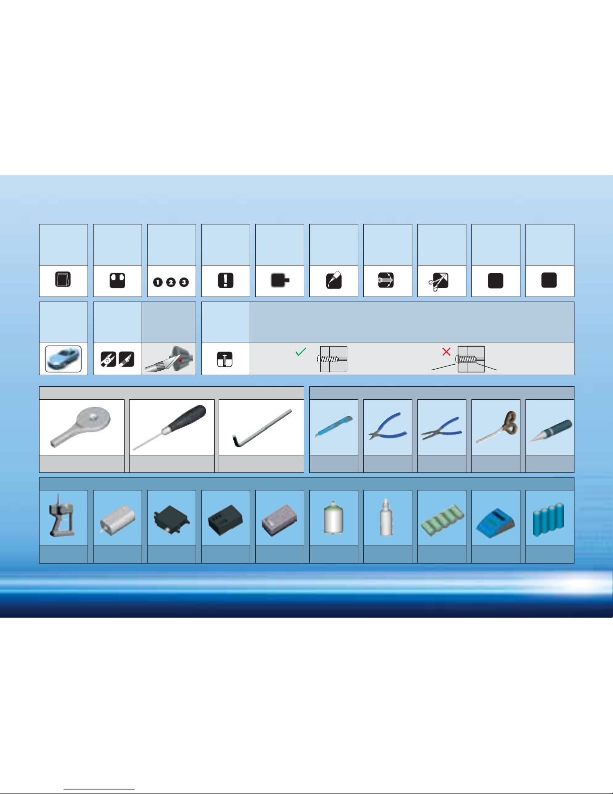
SYMBOLS USED
TOOLS REQUIRED
TOOLS INCLUDED
EQUIPMENT REQUIRED
Hobby Knife Side Cutters Needlenose Pliers Curved Scissors Hole Reamer
1:1
L=R
1
CA
2x
C
Self-tapping screws cut threads into the parts when being tightened. Excessive force may permanently damage
parts when tightening screws. It is recommended to stop tightening when the part is attached or when some
resistance is felt after the threaded portion enters the plastic.
Overtightened
CORRECT WRONG
The threads are stripped.
Micro Servo
Receiver
Transmitter Micro Motor
5-Cell Micro
Battery Pack
Battery Charger Transmitter
Batteries
Micro Speed
Controller
CA GlueLexan Paint
(Typically AA type)(Ni-MH recommended)
Differential Assembly Tool Phillips Screwdriver 1.5mm Allen Wrench
Assemble as
many times
as specified
(here twice)
Cut off
remaining
material
Cut off
remaining
material from all
plastic parts.
Cut off
shadded
portion
Ensure smooth
non-binding
movement
Apply instant
glue
Pivot ball
type used
Pay attention
here
Assemble in
the specified
order
Assemble left
and right
sides the
same way
Part bags
used
True-to-scale
diagram
Car
orientation
Tighten screw
gently
Page 4
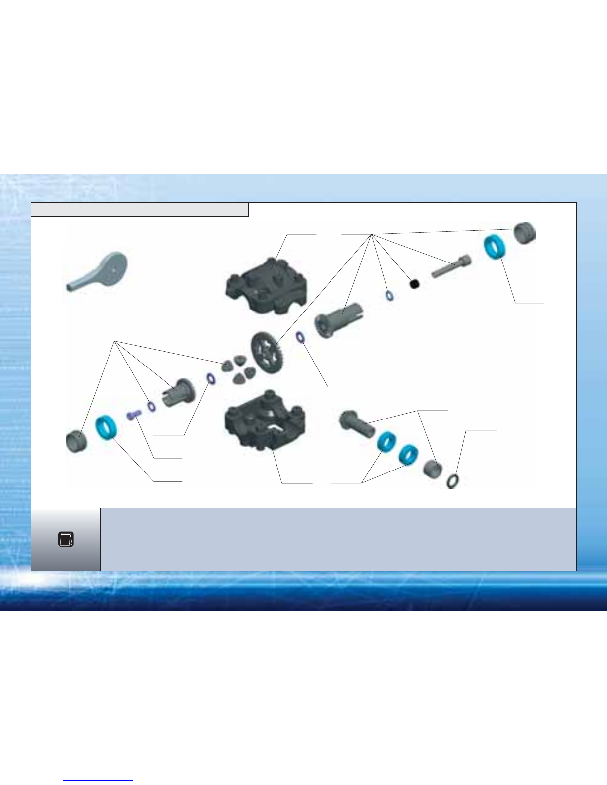
3
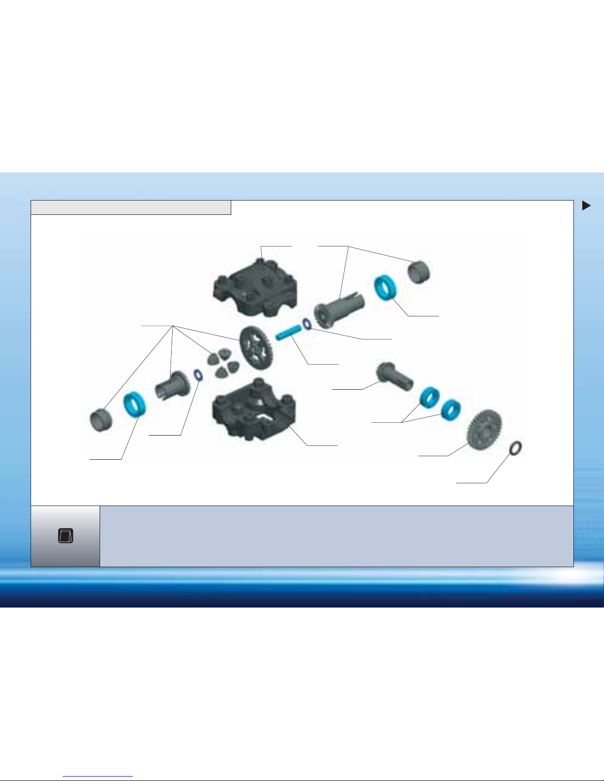
389343
309080
309080
389373
389373
385060
309040
385005
385060
385005
385005
DIFF ASSEMBLY TOOL
385550
309040 BALL-BEARING MR106ZZ 6x10x3 (2)
309080 BALL-BEARING MR128ZZ 8x12x3.5 (2)
385005 COMPOSITE FRONT GEAR DIFF. + DRIVESHAFT PINION GEAR
385060 GEARBOX CASE
385550 O-RING 4x1 (10)
389343 SCREW PHILLIPS 2.2 x 6 (10)
389373 WASHER S 3x6x0.3 (10)
1. FRONT DIFFERENTIAL
BAG
1
Page 5
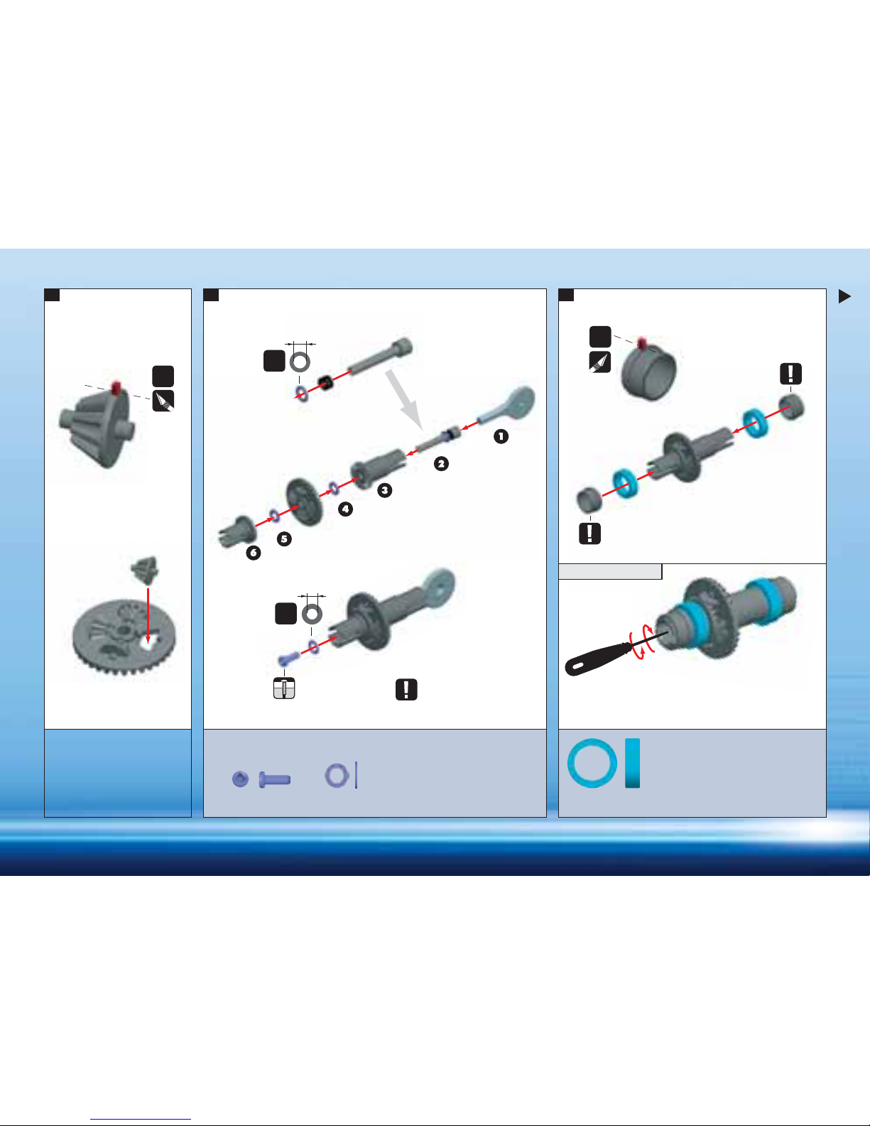
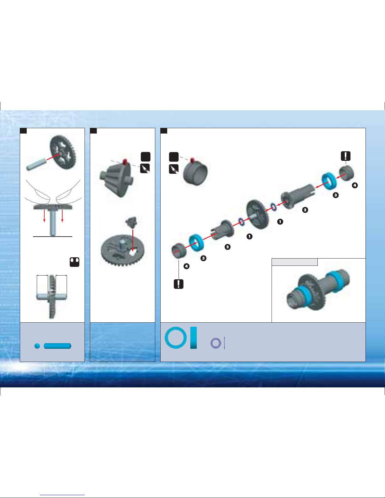
4
NOTE
ORIENTATION
TIGHTEN DIFF SCREW (CW) = TIGHTENS DIFF
LOOSEN DIFF SCREW (CCW) = LOOSENS DIFF
SET DIFF MEDIUM TIGHT SO IT ROTATES
SMOOTHLY WITHOUT BINDING
ADJUST THE DIFF SO
IT SPINS SMOOTHLY
TIGHTEN
GENTLY
NOTE
ORIENTATION
CUT OFF
CUT OFF
LARGER HOLE
SMALLER HOLE
1. 2. 3.
CCW.
CW.
ASSEMBLED VIEW
1:1
1:1
3.1mm
2.6mm
BLACK
SHIM
BLACK
SHIM
309080
BB 8x12x3.5
389373
SHIM 3x6x0.3
389343
2.2x6
4x
2x
Page 6
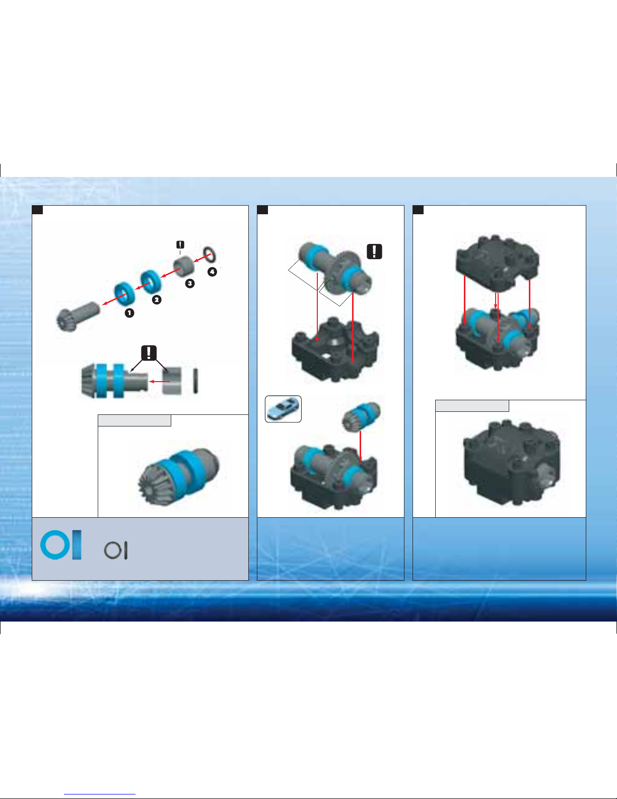
5
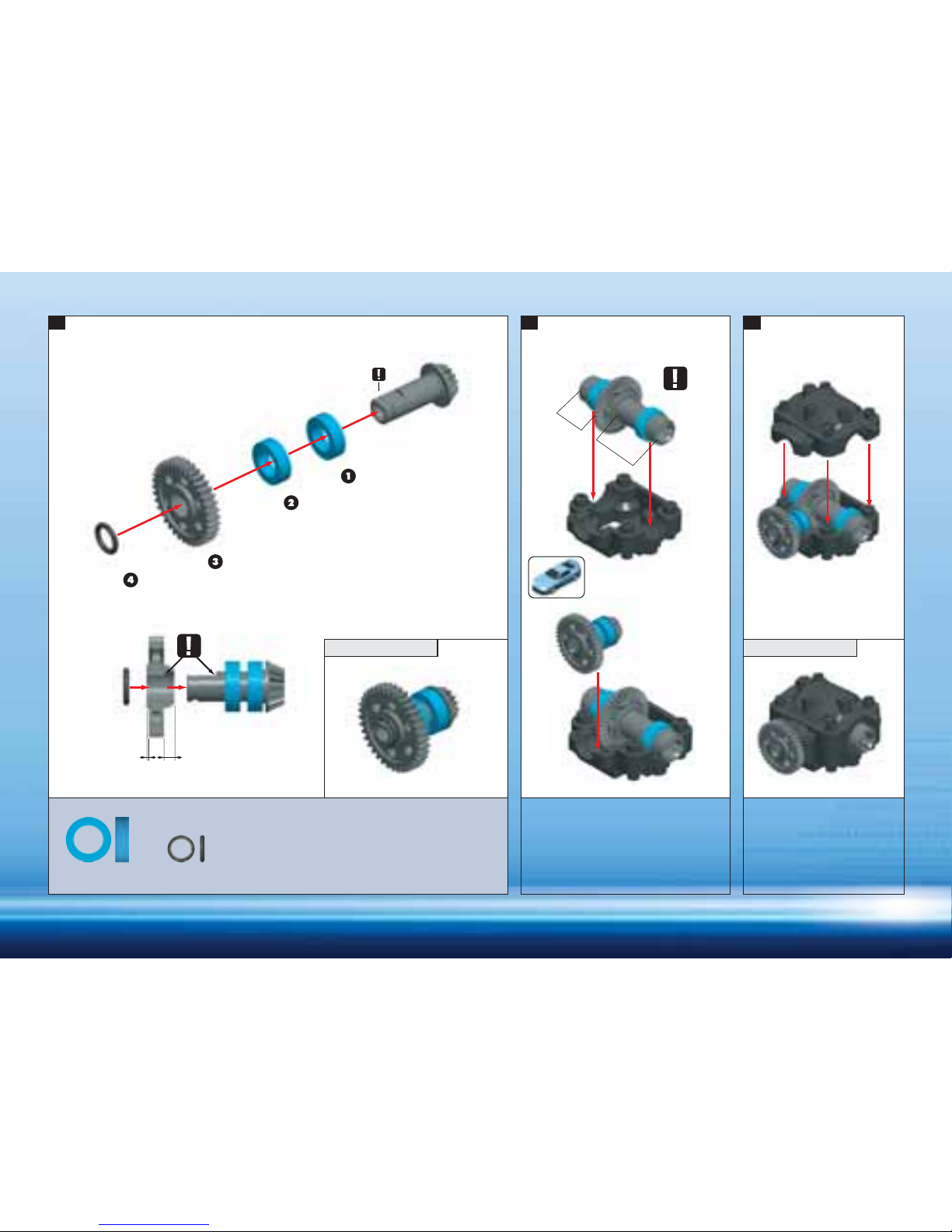
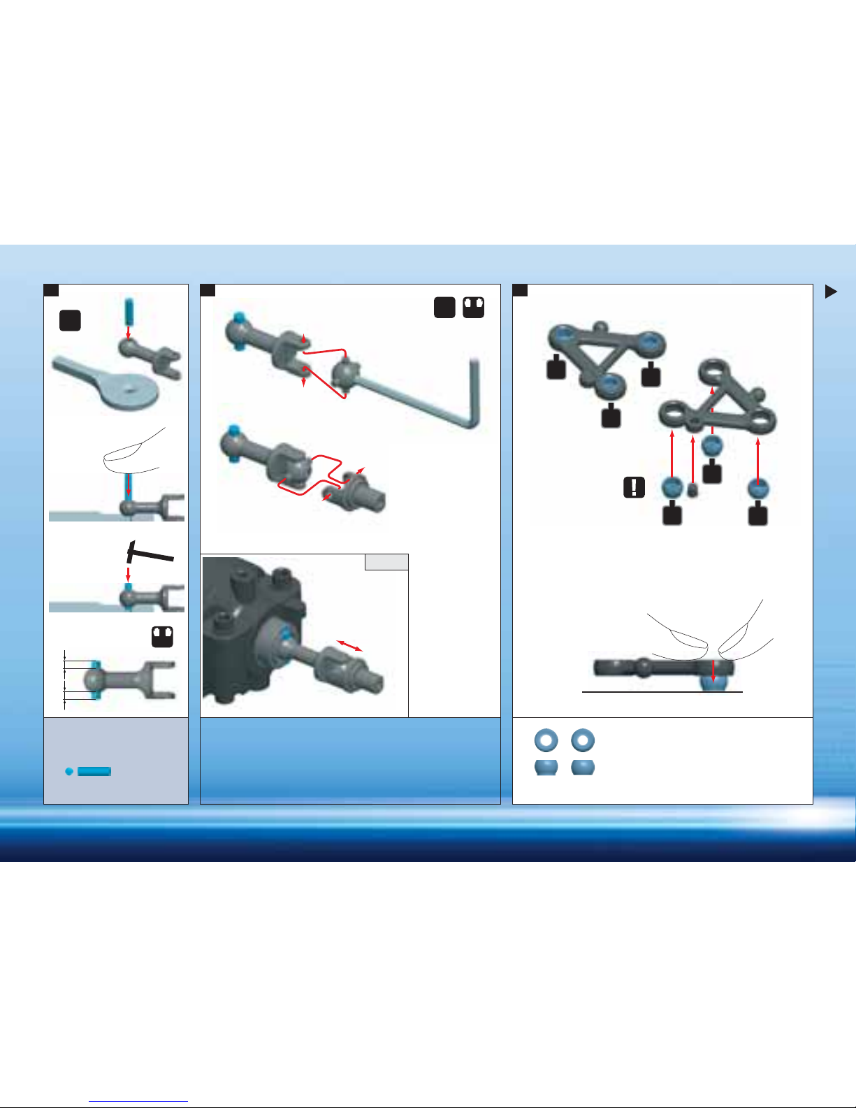
4. 5. 6.
ASSEMBLED VIEW
ASSEMBLED VIEW
L
O
N
G
SH
O
RT
309040
BB 6x10x3
385550
O 4x1
NOTE
ORIENTATION
ORIENTATION
NOTE
ORIENTATION
Page 7
6
309080
309460
389373
385000
309080
389373
385000
385060
385060
385000
309040
385736
385550
309040 BALL-BEARING MR106ZZ 6x10x3 (2)
309080 BALL-BEARING MR128ZZ 8x12x3.5 (2)
309460 PIN 3x16 (10)
385000 COMPOSITE REAR GEAR DIFF. + DRIVESHAFT PINION GEAR
385060 GEARBOX CASE
385550 O-RING 4x1 (10)
385736 SPUR GEAR 36T/48
389373 WASHER S 3x6x0.3 (10)
2. REAR DIFFERENTIAL
BAG
2
Page 8
7
1. 2. 3.
ASSEMBLED VIEW
NOTE
ORIENTATION
NOTE
ORIENTATION
SAME
LENGTH
LR
L=R
4x
CUT OFF CUT OFF
309080
BB 8x12x3.5
2x
389373
SHIM 3x6x0.3
309460
P 3x16
Page 9
8
L
O
N
G
SH
O
RT
NOTE
ORIENTATION
NOTE
ORIENTATION
385550
O 4x1
4. 5. 6.
ASSEMBLED VIEW ASSEMBLED VIEW
309040
BB 6x10x3
SHORTER LONGER
Page 10
9
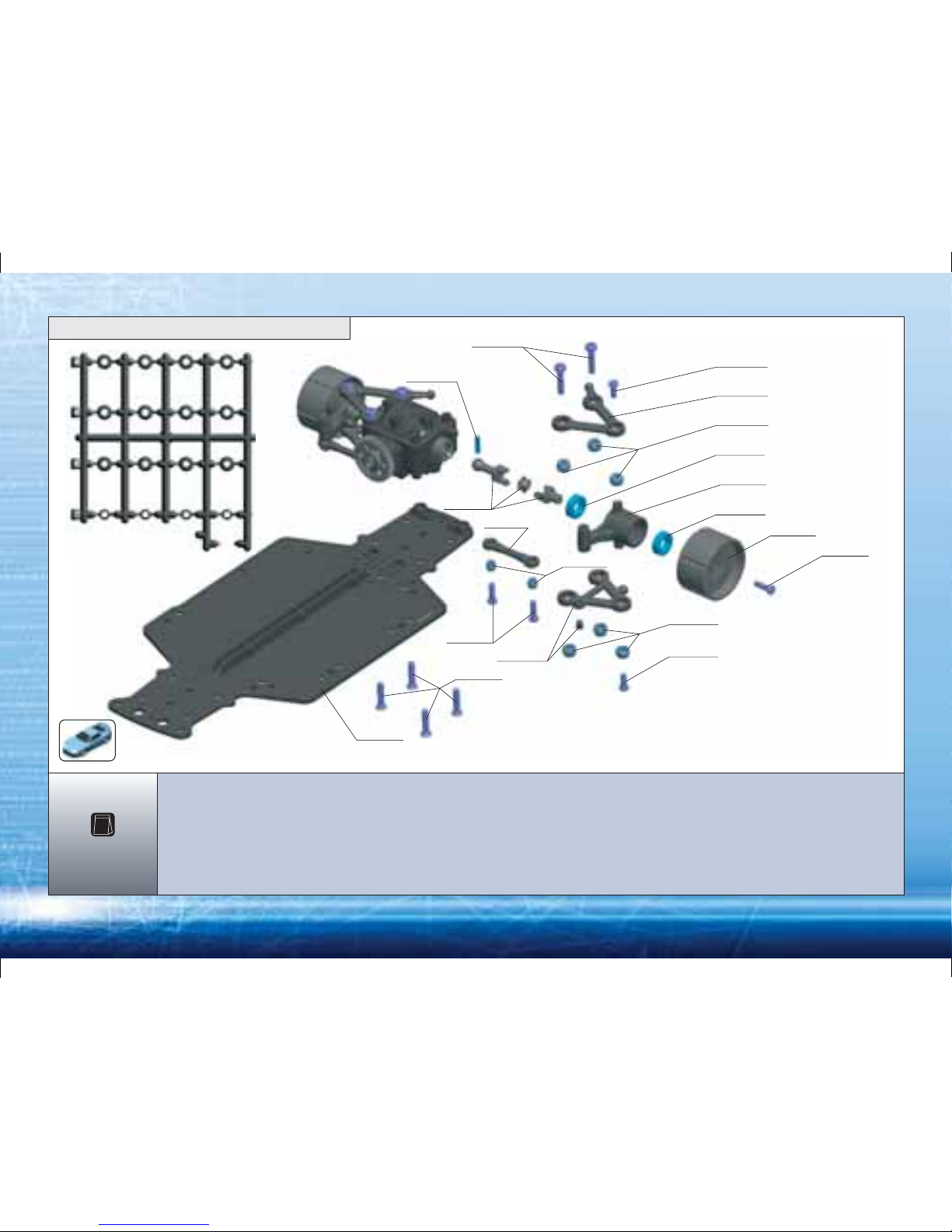
389336
387400
382100
381100
387400
387400
389344
389343
387400
382100
389343
389356
383200
389343
389995
309040
382200
309040
385200
309450
309040 BALL-BEARING MR106ZZ 6x10x3 (2)
309450 PIN 2x8 (10)
381100 COMPOSITE MICRO CHASSIS
382100 SET OF SUSPENSION ARMS, LOWER + UPPER (2+1+1)
382200 COMPOSITE SUSPENSION BLOCK, L+R (2)
383200 SET OF LINKAGES + BALL JOINTS
385200 COMPOSITE DRIVE SHAFT - SET (2)
387400 SET OF COMPOSITE PIVOT BALLS
389336 SCREW PHILLIPS FH 2.5x12 (10)
389343 SCREW PHILLIPS 2.2x6 (10)
389344 SCREW PHILLIPS 2.2x8 (10)
389356 SCREW PHILLIPS 2.5x12 (10)
389995 INNER WHEEL ADAPTORS, F+R
3. REAR SUSPENSION
BAG
3
Page 11
10
NOTE ORIENTATION
OF ALL PIVOT BALLS
309450
P 2x8
1. 2. 3.
SAME
LENGTH
LEFT LOWER ARM
RIGHT LOWER ARM
L
L=R
L=R
R
2x
2x
CHECK
A
A
A
A
B
B
AB
Page 12

11
L=R
A
A
A
A
NOTE ORIENTATION
OF ALL PIVOT BALLS
DOWNSTOP SCREWS
ARE IN LAST BAG
LR
B
B
TECH TIP
ADJUSTABLE DOWNSTOPS
4. 5.
REMOVE DOWNSTOP PIN
THREAD SET SCREW
RIGHT LEFT
RIGHT LEFT
309351
SB M3x4
AB
Page 13

12
ALIGN TAB AND SLOT
BEFORE TIGHTENING SCREW
TIGHTEN SCREW,
THEN LOOSEN A LITTLE BIT
CUTAWAY ASSEMBLED VIEW
L=R
2x
ORIENTATION
6. 7. 8.
389343
2.2x6
309040
BB 6x10x3
389343
2.2x6
TIGHTEN
GENTLY
Page 14

13
2x
C
C
L=R
389356
2.5x12
389356
2.5x12
389344
2.2x8
389344
2.2x8
9. 10. 11.
ASSEMBLED VIEW
C
TIGHTEN
GENTLY
MAKE SURE ARMS
MOVE FREELY
Page 15

14
389336
2.5x12
12.
ASSEMBLED VIEW
Page 16

15
387400
389345
387400
383200
383200
387400
389344
385512
382610
389356
389343
387400
382100
389343
389995
309040 382200
309040
385200
309450
382100
387400
389336
389343
309040 BALL-BEARING MR106ZZ 6x10x3 (2)
309450 PIN 2x8 (10)
382100 SET OF SUSPENSION ARMS, LOWER + UPPER (2+1+1)
382200 COMPOSITE SUSPENSION BLOCK, L+R (2)
382610 ADJ. TURNBUCKLE 34MM
383200 SET OF LINKAGES + BALL JOINTS
385200 COMPOSITE DRIVE SHAFT - SET (2)
385512 ALU MAIN DRIVESHAFT- SILVER
387400 SET OF COMPOSITE PIVOT BALLS
389336 SCREW PHILLIPS FH 2.5x12 (10)
389343 SCREW PHILLIPS 2.2x6 (10)
389344 SCREW PHILLIPS 2.2x8 (10)
389345 SCREW PHILLIPS 2.2x10 (10)
389356 SCREW PHILLIPS 2.5x12 (10)
389995 INNER WHEEL ADAPTORS, F+R
BAG
4
4. FRONT SUSPENSION
Page 17

16
1. 2. 3.1.
309450
P 2x8
AB
SAME
LENGTH
L
L=R
L=R
R
2x
2x
CHECK
NOTE ORIENTATION
OF ALL PIVOT BALLS
DO NOT USE DOWNSTOP
PIN ON LOWER ARMS
LEFT LOWER ARM
RIGHT LOWER ARM
A
A
B
A
A
B
Page 18

17
TECH TIP4. 5.
LR
L=R
A
A
A
B
B
A
ADJUSTABLE DOWNSTOPS
RIGHT LEFT
RIGHT LEFT
REMOVE DOWNSTOP PIN
THREAD SET
SCREW
DOWNSTOP SCREWS
ARE IN LAST BAG
309351
SB M3x4
ORIENTATION
NOTE ORIENTATION
OF ALL PIVOT BALLS
AB
Page 19

18
6. 7. 8.
389343
2.2x6
309040
BB 6x10x3
389343
2.2x6
L=R
2x
CUTAWAY ASSEMBLED VIEW
ALIGN TAB AND SLOT
BEFORE TIGHTENING SCREW
TIGHTEN
GENTLY
TIGHTEN SCREW,
THEN LOOSEN A LITTLE BIT
ORIENTATION
Page 20

19
10. 11.9.
ASSEMBLED VIEW
C
C
C
C
389356
2.5x12
389356
2.5x12
389344
2.2x8
389344
2.2x8
CC
56mm
ORIENTATION
4x
TIGHTEN
GENTLY
Page 21

20
14.13. 15.
ASSEMBLED VIEW
PLASTIC SHIM
389336
2.5x12
MAKE SURE ARMS
MOVE FREELY
ORIENTATION
Page 22

21
389334
389334
381225
381200
388000
389400
381340
381300
389400
389333
381300
388000
381200 LOWER FRONT BUMPER
381225 FOAM BUMPER - BLACK
381300 COMPOSITE BODY POSTS (4) + BODY CLIPS
381340 COMPOSITE REAR BODY POST HOLDER
388000 COMPOSITE SHOCK BODY SET (4)
389333 SCREW PHILLIPS FH 2.5 x 6 (10)
389334 SCREW PHILLIPS FH 2.5 x 8 (10)
389400 MICRO BODY CLIP
BAG
5
5. FRONT AND REAR FINAL ASSEMBLY
Page 23

22
389333
2.5x6
L=R
1. 2. 3.
ORIENTATION
ORIENTATION
Page 24

23
389334
2.5x8
PLASTIC SHIM
4. 5.
ASSEMBLED VIEW
1
1
2
2
1122
SHOCK POSITION
SHOCK POSITION
ORIENTATIONORIENTATION
Page 25

24
6. 7.
ASSEMBLED VIEW
ORIENTATION
Page 26

25
389344
389334
389334
389990
382000
389400
386310
386110
386200
382580
386200
389354
389640
385700
309350
389344
383200
387400
389312
386110
309350 HEX SCREW SB M3x3 (10)
382000 COMPOSITE MOTOR PLATE - SET
382580 COMPOSITE SERVO ARMS - SET
383200 SET OF LINKAGES + BALL JOINTS
385700 COMPOSITE PINION SET
386110 COMPOSITE BATTERY HOLDER SET FOR 5 BAT.
386200 COMPOSITE SERVO MOUNT+ ANTENNA HOLDER - SET
386310 ANTENNA
387400 SET OF COMPOSITE PIVOT BALLS
389312 SCREW PHILLIPS 2.0 x 4 (10)
389334 SCREW PHILLIPS FH 2.5 x 8 (10)
389344 SCREW PHILLIPS 2.2 x 8 (10)
389354 SCREW PHILLIPS 2.5 x 8 (10)
389400 MICRO BODY CLIP
389640 RUBBER TIRES + INSERTS F+R, 40 DEG
389990 XRAY MICRO WHEEL, F+R
BAG
6
6. FINAL ASSEMBLY
Page 27

26
1:1
1. 2. 3.
ASSEMBLED VIEW
389354
2.5x8
389334
2.5x8
USE A MICRO SERVO THAT IS SIMILAR TO
OR SMALLER THAN THE SERVO SHOWN
SCREW FROM SERVO
USE HORN FOR
YOUR SERVO
USE THE MICRO SERVO INCLUDED IN
XRAY M18 POWER PACK #389100
TIP
90°
Page 28

27
4. 5. 6.
ASSEMBLED VIEW ASSEMBLED VIEW
309350
SB M3x3
389312
2x4
USE XRAY MICRO STOCK
MOTOR INCLUDED
IN XRAY M18 POWER
PACK #389100
TIGHTEN
GENTLY
PRE-THREAD THE PINION
USE MICRO STOCK OR MODIFIED MICRO MOTOR
TIP
389344
2.2x8
1mm
ORIENTATION
Page 29

28
SPUR
GEAR
PINION
GEAR
FINAL
RATIO
ACCELERATION
SPEED
14
15
16
17
18
16
17
18
19
21
23
42
36
o
o
o
x
o
o
x
o
x
x
x
x - INCLUDED WITH KIT
o - AVAILABLE OPTION
7.50
7.00
6.56
6.18
5.83
5.62
5.29
5.00
4.74
4.29
3.91
INTERNAL RATIO 1:2.5
AVAILABLE
OPTION
INCLUDED
WITH KIT
7. TECH TIP
389334
2.5x8
PINION GEAR
SPUR GEAR
THE MOTOR STAND IS ADJUSTABLE:
1. RELEASE SCREWS FROM THE BOTTOM OF CHASSIS
2. MOVE THE MOTOR STAND AS NEEDED
3. TIGHTEN THE SCREWS
ADJUST MOTOR STAND SO GEARS MESH SMOOTHLY
ORIENTATION
Page 30

29
389334
2.5x8
ORIENTATIONORIENTATION
8. 9. 10.
USE MICRO BATTERY PACK
INCLUDED IN XRAY M18
POWER PACK #389100
USE 4 OR 5 CELL PACK OF 2/3A BATTERIES
INSTALL RECEIVER
(NOT INCLUDED)
DOUBLE-SIDED
TAPE
TIP
USE MICRO SPEED CONTROL XMC180
INCLUDED IN XRAY M18 POWER PACK
#398100
SCREWS INCLUDED WITH
XRAY XMC 180
SPEED CONTROL
INSTALL MICRO SPEED CONTROL
TIP
Page 31

30
11.
FRONT
REAR
12. 13.
NO SPACE
LARGER
SMALLER
NO SPACE
NOTE
ORIENTATION
NOTE
ORIENTATION
DO NOT USE
TOO MUCH GLUE
2x
2x
2x
2x
CA
2x
CA
2x
7
BAG
Page 32

31
C
L=R
FRONT 98mm 101mm
REAR 104mm 107mm
A B
B
15.14.
PLACE BRAKE DISKS
DECAL ON INNER WHEELS
PUSH WHEEL TABS ALL
THE WAY INTO THE SLOTS
ON THE INNER WHEEL
389344
2.2x8
A
A
A
B
A TRACKWIDTH (NARROW)
B TRACKWIDTH (WIDE)
Page 33

32
ELECTRONICS ASSEMBLY
BATTERY PACK
STEERING SERVO
ANTENNA WIRE
RECEIVER
SPEED CONTROL
M18 POWER PACK ASSEMBLY SHOWN
USE XRAY M18 POWER PACK #389100 THAT INCLUDES ALL
ELECTRONICS REQUIRED FOR OPERATION. (RECEIVER & TRANSMITTER ARE NOT INCLUDED)
INSTALL ELECTRONICS ACCORDING
TO MANUFACTURER'S INSTRUCTIONS
MOTOR
TIP
1CH
2CH
Page 34

33
4x
HOLE FOR
BODY POSTS
Cut out body and wing along trim lines
Apply window masks inside body
Mask and paint body using polycarbonate paint
Apply stickers
4x
HOLE FOR
WING
WING ASSEMBLY
3mm
3mm
4.5mm
1x
HOLE FOR
ANTENNA
4.5mm
4.5mm
4.5mm
4.5mm
BODY MOUNTING
Page 35

• This product is not suitable for children except under
the direct supervision of an adult.
• Carefully read all manufacturers warnings and cautions
for any parts used in the construction and use of your model.
• Assemble this kit only in places away from the reach
of very small children.
• First-time builders should seek advice from people who have building
experience in order to assemble the model correctly and to allow the
model to reach its performance potential.
• Insulate any exposed electrical wiring (using heat shrink tubing
or electrical tape) to prevent dangerous short circuits.
• Exercise care when using tools and sharp instruments.
• Take care when building; some parts may have sharp edges.
• Keep small parts out of reach of small children.
• Do not put fingers or any objects inside or near rotating or moving
parts.
• Immediately after using your model, do NOT touch equipment
or electronic components on the model because they may
generate high temperatures.
• Follow the operating instructions for the radio equipment at all times.
• Be sure that your operating frequency is clear before turning
on or running your model, and never share the same frequency with
somebody else at the same time. Ensure that others are aware
of the operating frequency you are using and when you are using it.
• Always turn on your transmitter before you turn on the receiver/speed
controller or connect the battery pack. Always turn off the
receiver/speed controller or disconnect the battery pack
before turning your transmitter off.
• Keep the wheels of the model off the ground when checking
the operation of the radio equipment.
• Disconnect the battery pack before storing your model.
• When learning to operate your model, go to an area that has no
obstacles that can damage your model if your model suffers a
collision.
• Remove any sand, mud, dirt, grass or water before putting
your model away.
• Use a recommended charger for the batteries and follow the
instructions correctly. Over-charging, incorrect charging, or using
inferior chargers can cause the batteries to become dangerously hot.
• Regularly check the charger for potential hazards such as damage
to the cable, plug, casing or other defects. Ensure that any damage
is rectified before using the charger again.
• Do not allow the transmitter batteries to become low on charge,
otherwise you risk losing control of the model.
• Do not allow any metal part to short circuit the batteries, speed
control, or other electrical/electronic device on the model.
• If the model behaves strangely, immediately stop the model,
check and clear the problem.
• Do not stall the motor. The speed control will fail within seconds if
power is applied to the motor when the car cannot move.
DO NOT USE YOUR MODEL:
• Near real cars, animals, or people that are unaware
that an R/C car is being driven.
• In places where children and people gather
• In residential districts and parks
• In limited indoor spaces
• In wet conditions
• In the street
IMPORTANT NOTES
Take adequate safety precautions prior to operating this model. You are responsible for this model’s assembly and safe operation.
Disregard of the any of the above cautions may lead to accidents, personal injury, or property damage.
XRAY MODEL RACING CARS assumes no responsibility for any injury, damage, or misuse of this product during assembly or operation, nor any
addictions that may arise from the use of this product.
Page 36

XRAY MODEL RACING CARS, P.O.BOX 103, 911 50 TRENČÍN, SLOVAKIA, EUROPE
XRAY is a member of myTSN.com
 Loading...