

Page 1
Page 2

2
BEFORE YOU START
The GTX8 is a high-competition, high-quality, 1/10-scale nitro car intended for persons aged 16 years and older
with previous experience building and operating RC model racing cars. This is not a toy; it is a precision racing
model. This model racing car is not intended for use by beginners, inexperienced customers, or by children
without direct supervision of a responsible, knowledgeable adult. If you do not fulfill these requirements, please
return the kit in unused and unassembled form back to the shop where you have purchased it.
Before building and operating your GTX8, YOU MUST read through all of the operating instructions and
instruction manual and fully understand them to get the maximum enjoyment and prevent unnecessary
damage.
Read carefully and fully understand the instructions before beginning assembly.
Make sure you review this entire manual, the included set-up book, and examine all details carefully. If for some
reason you decide the GTX8 is not what you wanted or expected, do not continue any further. Your hobby dealer
cannot accept your GTX8 kit for return or exchange after it has been partially or fully assembled.
Contents of the box may differ from pictures. In line with our policy of continuous product development, the exact
specifications of the kit may vary without prior notice.
SAFETY PRECAUTIONS
WARNING: This product contains a chemical known to the state of California to cause cancer and birth
defects or other reproductive harm.
CAUTION: CANCER HAZARD
Wash thoroughly after using. DO NOT use product while eating, drinking or using tobacco products. May
cause chronic effects to gastrointestinal tract, CNS, kidneys, and blood. MAY CAUSE BIRTH DEFECTS.
When building, using and/or operating this model always wear protective glasses and gloves.
Take appropriate safety precautions prior to operating this model. You are responsible for this model‘s
assembly and safe operation! Please read the instruction manual before building and operating this model
and follow all safety precautions. Always keep the instruction manual at hand for quick reference, even after
completing the assembly. Use only genuine and original authentic XRAY parts for maximum performance.
Using any third party parts on this model will void guaranty immediately.
Improper operation may cause personal and/or property damage. XRAY and its distributors have no
control over damage resulting from shipping, improper construction, or improper usage. XRAY assumes and
accepts no responsibility for personal and/or property damages resulting from the use of improper building
materials, equipment and operations. By purchasing any item produced by XRAY, the buyer expressly
warrants that he/she is in compliance with all applicable federal, state and local laws and regulation
regarding the purchase, ownership and use of the item. The buyer expressly agrees to indemnify and hold
harmless XRAY for all claims resulting directly or indirectly from the purchase, ownership or use of the
product. By the act of assembling or operating this product, the user accepts all resulting liability. If the buyer
is not prepared to accept this liability, then he/she should return this kit in new, unassembled, and unused
condition to the place of purchase.
• Keep the wheels of the model off the ground when checking the operation of the radio equipment.
• Disconnect the battery pack before storing your model.
• When learning to operate your model, go to an area that has no obstacles that can damage your model
if your model suffers a collision.
• Remove any sand, mud, dirt, grass or water before putting your model away.
• If the model behaves strangely, immediately stop the model, check and clear the problem.
• To prevent any serious personal injury and/or damage to property, be responsible when operating all
remote controlled models.
• The model car is not intended for use on public places and roads or areas where its operation can conflict with
or disrupt pedestrian or vehicular traffic.
• Because the model car is controlled by radio, it is subject to radio interference from many sources that
are beyond your control. Since radio interference can cause momentary loss of control, always allow a
safety margin in all directions around the model in order to prevent collisions.
• Do not use your model:
- Near real cars, animals, or people that are unaware that an RC car is being driven.
- In places where children and people gather
- In residential districts and parks
- In limited indoor spaces
- In wet conditions
- In the street
- In areas where loud noises can disturb others, such as hospitals and residential areas.
- At night or anytime your line of sight to the model may be obstructed or impaired in any way.
To prevent any serious personal injury and/or damage to property, please be responsible when operating
all remote controlled models.
IMPORTANT NOTES – GENERAL
• This product is not suitable for children under 16 years of age without the direct supervision of a
responsible and knowledgeable adult.
• Carefully read all manufacturers warnings and cautions for any parts used in the construction and use
of your model.
• Assemble this kit only in places away from the reach of very small children.
• First-time builders and users should seek advice from people who have building experience in order to
assemble the model correctly and to allow the model to reach its performance potential.
• Exercise care when using tools and sharp instruments.
• Take care when building, as some parts may have sharp edges.
• Keep small parts out of reach of small children. Children must not be allowed to put any parts in their
mouth, or pull vinyl bag over their head.
• Read and follow instructions supplied with paints and/or cement, if used (not included in kit).
• Immediately after using your model, do NOT touch equipment on the model such as the motor and
speed controller, because they generate high temperatures. You may seriously burn yourself seriously
touching them.
• Follow the operating instructions for the radio equipment at all times.
• Do not put fingers or any objects inside rotating and moving parts, as this may cause damage or serious injury as your finger, hair, clothes, etc. may get caught.
• Be sure that your operating frequency is clear before turning on or running your model, and never
share the same frequency with somebody else at the same time. Ensure that others are aware of the
operating frequency you are using and when you are using it.
• Use a transmitter designed for ground use with RC cars. Make sure that no one else is using the same
frequency as yours in your operating area. Using the same frequency at the same time, whether it is
driving, flying or sailing, can cause loss of control of the RC model, resulting in a serious accident.
• Always turn on your transmitter before you turn on the receiver in the car. Always turn off the receiver
before turning your transmitter off.
FAILURE TO FOLLOW THESE INSTRUCTIONS WILL BE CONSIDERED AS ABUSE AND/OR NEGLECT.
CUSTOMER SUPPORT
XRAY Europe
K Výstavisku 6992
91101 Trenčín
Slovakia, EUROPE
Phone: +421-32-7401100
Fax: +421-32-7401109
Email: info@teamxray.com
We have made every effort to make these instructions as easy to understand as possible. However, if you have
any difficulties, problems, or questions, please do not hesitate to contact the XRAY support team at info@
teamxray.com. Also, please visit our Web site at www.teamxray.com to find the latest updates, set-up information, option parts, and many other goodies. We pride ourselves on taking excellent care of our customers.
You can join thousands of XRAY fans and enthusiasts in our online community at: www.teamxray.com
XRAY USA
RC America, 2030 Century Center Blvd #15 Irving,
TX 75062
USA
Phone: (800) 519-7221 * (214) 744-2400
Fax: (214) 744-2401
Email: xray@rcamerica.com
IMPORTANT NOTES – NITRO ENGINES
• Always test the brakes and the throttle before starting your engine to avoid losing control of the model.
• Make sure the air filter is clean and oiled.
• Never run your engine without an air filter. Your engine can be seriously damaged if dirt and debris get
inside the engine.
• For proper engine break-in, please refer to the manual that came with the engine.
• Do not run near open flames or smoke while running your model or while handling fuel.
• Some parts will be hot after operation. Do not touch the exhaust or the engine until they have cooled.
These parts may reach 275°F during operation!
Page 3

3
IMPORTANT NOTES – ELECTRICAL
• Insulate any exposed electrical wiring (using heat shrink tubing or electrical tape) to prevent dangerous
short circuits. Take maximum care in wiring, connecting and insulating cables. Make sure cables are
always connected securely. Check connectors for if they become loose. And if so, reconnect them securely.
Never use R/C models with damaged wires. A damaged wire is extremely dangerous, and can cause
short-circuits resulting in fire. Please have wires repaired at your local hobby shop.
• Low battery power will result in loss of control. Loss of control can occur due to a weak battery in either
the transmitter or the receiver. Weak running battery may also result in an out of control car if your car‘s
receiver power is supplied by the running battery. Stop operation immediately if the car starts to slow
down.
• When not using RC model, always disconnect and remove battery.
• Do not disassemble battery or cut battery cables. If the running battery short-circuits, approximately
300W of electricity can be discharged, leading to fire or burns. Never disassemble battery or cut battery
cables.
• Use a recommended charger for the receiver and transmitter batteries and follow the instructions
correctly. Over-charging, incorrect charging, or using inferior chargers can cause the batteries to become
dangerously hot. Recharge battery when necessary. Continual recharging may damage battery and, in
the worst case, could build up heat leading to fire. If battery becomes extremely hot during recharging,
please ask your local hobby shop for check and/or repair and/or replacement.
• Regularly check the charger for potential hazards such as damage to the cable, plug, casing or other
defects. Ensure that any damage is rectified before using the charger again. Modifying the charger may
cause short-circuit or overcharging leading to a serious accident. Therefore do not modify the charger.
• Always unplug charger when recharging is finished.
• Do not recharge battery while battery is still warm. After use, battery retains heat. Wait until it cools
down before charging.
• Do not allow any metal part to short circuit the receiver batteries or other electrical/electronic device on
the model.
• Immediately stop running if your RC model gets wet as may cause short circuit.
• Please dispose of batteries responsibly. Never put batteries into fire.
WARRANTY
XRAY guarantees this model kit to be free from defects in both material and workmanship within 30 days
of purchase. The total monetary value under warranty will in no case exceed the cost of the original kit
purchased. This warranty does not cover any components damaged by use or modification or as a result
of wear. Part or parts missing from this kit must be reported within 30 days of purchase. No part or parts
will be sent under warranty without proof of purchase. Should you find a defective or missing part, contact
the local distributor. Service and customer support will be provided through local hobby store where you
have purchased the kit, therefore make sure to purchase any XRAY products at your local hobby store. This
model racing car is considered to be a high-performance racing vehicle. As such this vehicle will be used
in an extreme range of conditions and situations, all which may cause premature wear or failure of any
component. XRAY has no control over usage of vehicles once they leave the dealer, therefore XRAY can only
offer warranty against all manufacturer‘s defects in materials, workmanship, and assembly at point of sale
and before use. No warranties are expressed or implied that cover damage caused by what is considered
normal use, or cover or imply how long any model cars‘ components or electronic components will last before
requiring replacement.
Due to the high performance level of this model car you will need to periodically maintain and replace
consumable components. Any and all warranty coverage will not cover replacement of any part or
component damaged by neglect, abuse, or improper or unreasonable use. This includes but is not limited to
damage from crashing, chemical and/or water damage, excessive moisture, improper or no maintenance,
or user modifications which compromise the integrity of components. Warranty will not cover components
that are considered consumable on RC vehicles. XRAY does not pay nor refund shipping on any component
sent to XRAY or its distributors for warranty. XRAY reserves the right to make the final determination of the
warranty status of any component or part.
Limitations of Liability
XRAY makes no other warranties expressed or implied. XRAY shall not be liable for any loss, injury or
damages, whether direct, indirect, special, incidental, or consequential, arising from the use, misuse, or
abuse of this product and/or any product or accessory required to operate this product. In no case shall
XRAY‘s liability excess the monetary value of this product.
Take adequate safety precautions prior to operating this model. You are responsible for this model’s
assembly and safe operation.
Disregard of the any of the above cautions may lead to accidents, personal injury, or property
damage. XRAY MODEL RACING CARS assumes no responsibility for any injury, damage, or
misuse of this product during assembly or operation, nor any addictions that may arise from
the use of this product.
All rights reserved.
QUALITY CERTIFICATE
XRAY MODEL RACING CARS uses only the highest quality materials, the best compounds for molded parts
and the most sophisticated manufacturing processes of TQM (Total Quality Management). We guarantee
that all parts of a newly-purchased kit are manufactured with the highest regard to quality. However, due
to the many factors inherent in model racecar competition, we cannot guarantee any parts once you start
racing the car. Products which have been worn out, abused, neglected or improperly operated will not be
covered under warranty. We wish you enjoyment of this high-quality and high-performance RC car and wish
you best success on the track!
Please note that raw materials such as aluminum, steel, brass, fibreglass, or carbon fibre may
have small scratches on the surface which is a standard characteristic of any raw material.
Scratches on the surface of any materials are NOT considered to be material defects.
Products may potentially have small amounts of corrosion on them. This may be caused by variances in
weather during different times of the year, humidity in the shop or during shipping, and other contributing
factors. Even though we have taken all precautions and protection methods to prevent corrosion, these small
amounts of corrosion (if present) are unavoidable and considered to be acceptable.
In line with our policy of continuous product development, the exact specifications of the kit may vary. In the unlikely event of any problems with your new kit, you should contact the model shop
where you purchased it, quoting the part number. We do reserve all rights to change any specification without prior notice. All rights reserved.
R/C & BUILDING TIPS
• Make sure all fasteners are properly tightened. Check them periodically.
• Make sure that chassis screws do not protrude from the chassis.
•
For the best performance, it is very important that great care is taken to ensure the free movement of all parts.
• Clean all ball-bearings so they move very easily and freely.
• Tap or pre-thread the plastic parts when threading screws.
• Self-tapping screws cut threads into the parts when being tightened. Do not use excessive force when
tightening the self-tapping screws because you may strip out the thread in the plastic. We recommended
you stop tightening a screw when you feel some resistance.
•
Ask your local hobby shop for any advice.
Please support your local hobby shop. We at XRAY Model Racing Cars support all local hobby dealers.
Therefore we ask you, if at all possible, to purchase XRAY products at your hobby dealer and give them
your support like we do. If you have difficulty finding XRAY products, please check out www.teamxray.com to
get advice, or contact us via email at info@teamxray.com, or contact the XRAY distributor in your country.
IMPORTANT NOTES – NITRO FUEL
• Handle fuel only outdoors. Never handle nitro fuel indoors, or mix nitro fuel in a place where ventilation
is bad.
• Only use nitro fuel for R/C models. Do not use gasoline or kerosene in R/C models as it may cause a fire
or explosion, and ruin your engine.
• Nitro fuel is highly inflammable, explosive, and poisonous. Never use fuel indoors or in places with open
fires and sources of heat.
• Always keep the fuel container cap tightly shut.
• Always read the warning label on the fuel container for safety information.
• Nitro-powered model engines emit poisonous vapors and gasses. These vapors irritate eyes and can be highly
dangerous to your health. We recommend wearing rubber or vinyl gloves to avoid direct contact with nitro fuel.
• Nitro fuel for RC model cars is made of the combination of the methyl alcohol, castor or synthetic oil,
nitro methane etc. The flammability and volatility of these elements is very high, so be very careful
during handling and storage of nitro fuel.
•
Keep nitro fuel away from open flame, sources of heat, direct sunlight, high temperatures, or near
batteries.
•
Store fuel in a cool, dry, dark, well-ventilated place, away from heating devices, open flames, direct
sunlight, or batteries. Keep nitro fuel away from children.
• Do not leave the fuel in the carburetor or fuel tank when the model is not in use. There is danger that
the fuel may leak out.
•
Wipe up any spilled fuel with a cloth
• Be aware of spilled or leaking fuel. Fuel leaks can cause fires or explosions.
• Do not dispose of fuel or empty fuel containers in a fire. There is danger of explosion.
Page 4
4
To ensure that you always have access to the most up-todate version of the XRAY Set-up Book, XRAY will now be
offering only the digital online version at our website
at www.teamxray.com. By offering this online version
instead of including a hardcopy printed version in kits,
you will always be assured of having the most current
updated version.
SYMBOLS USED
L=R
2x
CA
OIL
Part bags used Assemble left and
right sides the
same way
Assemble in the
specified order
Pay attention
here
Assemble as
many times
as specified
(here twice)
Apply instant
glue
Cut off shaded
portion
Cut off
remaining
material
Tighten screw
gently
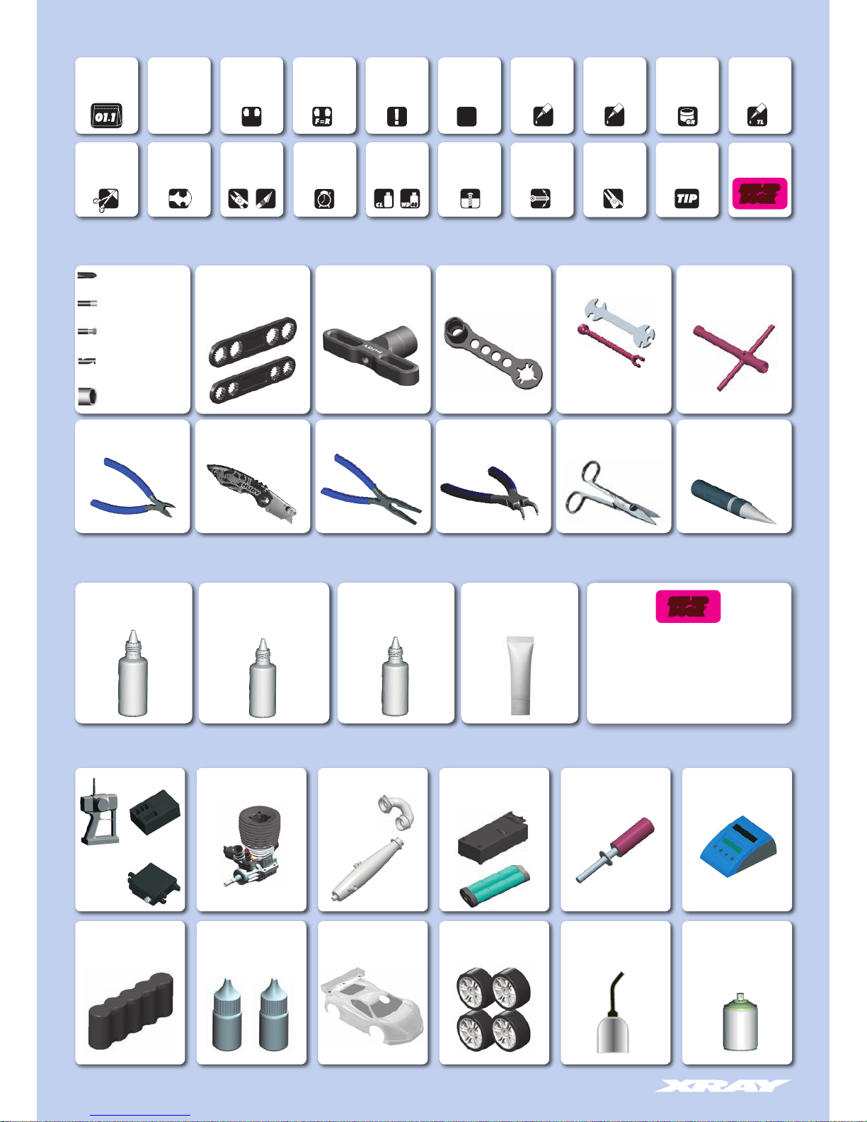
TOOLS REQUIRED
EQUIPMENT REQUIRED
TOOLS & EQUIPMENT INCLUDED NOT INCLUDED
Assemble front
and rear the same
way
Apply oil
Use special
tool
Silicone Shock Oil
(HUDY #106411 1000cSt 100ml)
Silicone Diff Oil
(HUDY #106561 60.000cSt 100ml)
(HUDY #106631 300.000cSt 100ml)
Air Filter Oil
(HUDY #106240)
Receiver Pack
Transmitter
Engine Manifold & Exhaust Glow Plug IgniterStarter Box & Battery Pack
(HUDY #104500)
Steering and
Throttle Servos
Battery Charger
Receiver
Lexan™ PaintFuel + Fuel Bottle
(HUDY #104200)
Special Tool for all turnbuckles,
nuts (HUDY #181090)
Turnbuckle Wrench
(HUDY #181040 4mm)
(HUDY #181050 5mm)
Phillips 5.0mm
(HUDY TOOLS)
Socket 5.0/5.5mm
(HUDY TOOLS)
Allen 1.5/2.0/2.5/3.0mm
(HUDY TOOLS)
17mm Wheel Nut Tool
(HUDY #107570)
Side Cutters
(HUDY #189010)
Body Reamer
(HUDY #107600)
or
(HUDY #107601)
Cross Wrench
(HUDY #107581)
Flywheel Tool
(HUDY #182015)
Scissors
(HUDY #188990)
Needle Nose Pliers
(HUDY #189020)
Snap Ring Pliers
(HUDY #189040)
➊ ➋ ➌
Apply grease Apply
threadlock
Ensure smooth
non-binding
movement
Use pliers Follow tip here
Arm Reamer 3mm/4mm
(HUDY TOOLS)
Graphite Grease
(HUDY #106210)
Wheels & TiresGT BODY
(XRAY #359730)
Threadlock & CA Glue
Follow Set-up
Book
Use cleaner
or WD-40®
Time
Ball Allen 2.5mm
(HUDY TOOLS)
BOOK
SET-UP
BOOK
SET-UP
Pinion Tool Set
(XRAY #349901)
Pocket Hobby Knife
(HUDY #188981)
Page 5
5
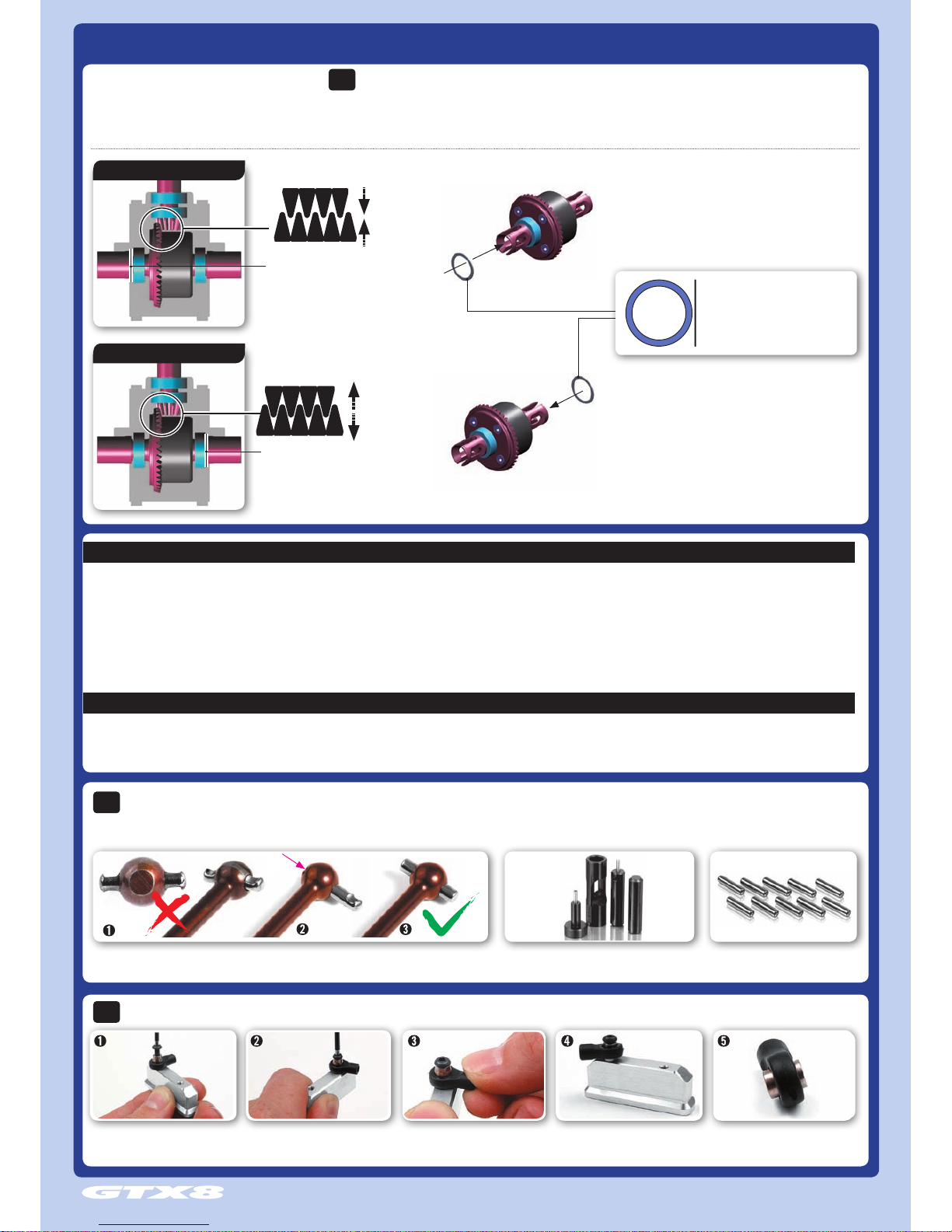
XB8 TECH TIPS
If there is too much or too little diff side play, this may create non-optimal gear mesh between the diff gear and the pinion drive gear. This is easily resolved by inserting 1 or 2 of the included thin shims behind a diff
outdrive ball-bearing, depending on how much play there is.
FRONT & REAR DIFF GEAR MESH ADJUSTMENT
THE LOCATION OF THE SHIM(S) DEPENDS ON WHETHER YOU ARE TRYING TO CLOSE OR OPEN THE GAP:
TO CLOSE A WIDE GAP
TO OPEN A NARROW GAP
TIP
insert shim(s) here
insert shim(s) here
To CLOSE a wide gap:
add 1 or 2 shims against diff spur gear
To OPEN a narrow gap:
add 1 or 2 shims on the other side of the diff, away from spur gear
OPEN A NARROW GAP
CLOSE A WIDE GAP
#962130 S 13 x 16 x 0.2 mm (10)
#962131 S 13 x 16 x 0.1 mm (10)
WASHER
TIP
Tighten screw until pivot ball is tight
against block.
Lift ball joint until it snaps into place over
pivot ball. Ball joint should move freely.
The finished joint. Loosen and remove screw.
INSTALLING PIVOT BALLS INTO COMPOSITE BALL-JOINTS
Place the pivot ball on the ball joint
and use a screw to tighten it to an
engine mount or some other part.
DRIVE SHAFT PIN SERVICING
TIP
To enjoy the longest possible lifespan of the drive shafts and diff outdrives, it is extremely important to properly service the drive shaft pins.
Inspect the pins after every 3 hours of runtime. If the pins show any wear, replace them with new pins.
For easy drive pin replacements use #106000
HUDY Drive Pin Replacement Tool.
To replace the worn pins use only
premium HUDY drive pins #106050.
Do not use drive shafts
when the pins are worn.
Press out the worn pins.
Press in new pins and
regularly inspect for wear.
SUSPENSION & DRIVETRAIN MAINTENANCE
• Check suspension for free movement during building and operation, and especially after running
and if you have crashed the car. If the suspension does not move freely, use the appropriate HUDY
Arm Reamer to clean and resize the holes of the suspension arms.
• Regularly check the drive shaft pins (both side and center) and if they show any wear must be
immediately replaced by new pins. If the car is run with worn pins, excessive wear on the diff
outdrives will result. The 106000 HUDY Drive Pin Replacement Tool (for 3mm Pins) is a compact,
rugged multi-use tool set for replacing 3mm drive pins in drive shafts. Use the HUDY replacement
drive shaft pins 3x14 (#106050).
• Regularly inspect and replace the connecting pins which connect the center drive shafts with the
pinion gear, and also the pins that connect the wheel drive shafts with wheel axles. Use HUDY
Graphite Grease to lubricate the drive shaft connecting joints and the diff gears.
• Pivot balls and ball-joints will naturally wear for some time and will generate play. If there is too
much play the pivot balls and ball joints need to be replaced.
• If the car is run in wet conditions, apply WD-40® on all drivetrain parts before the run. After the
run, clean and dry the parts again.
HUDY SPRING STEEL™
The HUDY Spring Steel™ used in the car is the strongest and most durable steel material on the RC market. While items made from HUDY Spring Steel™ are still subject to wear, the lifespan is considerably
longer than any other material. As parts made from HUDY Spring Steel™ wear, the brown color will after some time “go down” but it will not affect the strength of the material. The brown color is only a
surface treatment and if the brown color will wear the durability of the part will be still strong.
Page 6
6
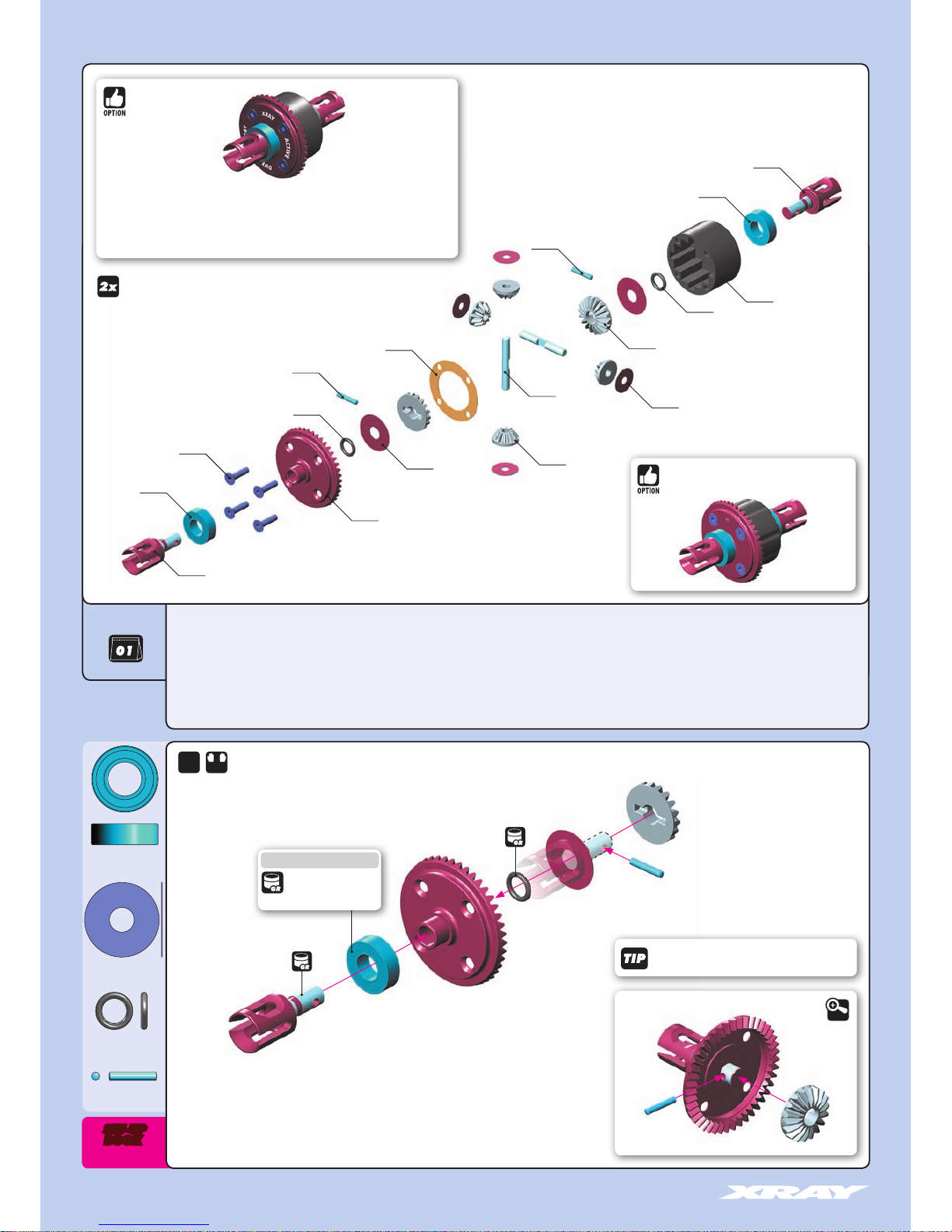
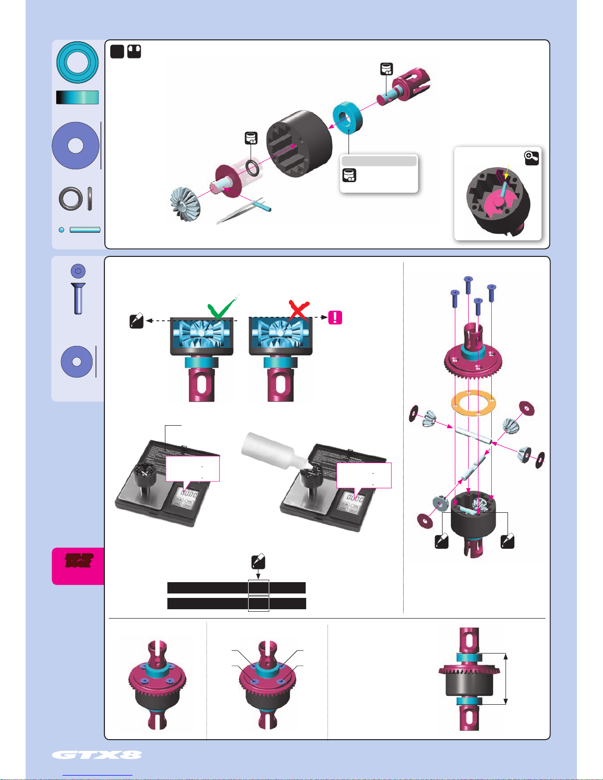
DIFFERENTIAL GEARS
STEP DETAIL
➎
➎➏
➏
DETAIL
➊
➋
➌
➍
➎
➏
Graphite Grease
(HUDY #106210)
Graphite Grease
(HUDY #106210)
Use HUDY Ball-Bearing Grease
#106220 - STANDARD
#106221 - BLUE
#106222 - RED
1. FRONT & REAR DIFFERENTIALS
2x
F=R
35 5003 FRONT/REAR DIFFERENTIAL 46T - SET
35 5020 COMPOSITE DIFFERENTIAL CASE
35 5030 STEEL DIFF BEVEL & SATELLITE GEARS (2+4)
35 5046 FRONT/REAR DIFF LARGE BEVEL GEAR 46T - HUDY STEEL
35 5063 F/R DIFF OUTDRIVE ADAPTER - LIGHTW. - HUDY SPRING STEEL™ (2)
35 5080 DIFF PIN (2)
35 5090 DIFF GASKET (4)
90 3312 HEX SCREW SFH M3x12 (10)
94 0816 HIGH-SPEED BALL-BEARING 8x16x5 BLUE COVERED (2)
96 4030 WASHER S 3.5x12x0.2 (10)
96 4060 WASHER S 6x18x0.2 (10)
97 1060 SILICONE O-RING 6x1.5 (10)
98 0212 PIN 2x11.6 (10)
BAG
940816
903312
355046
964060
355030
355030
971060
355020
940816
355090
964030
980212
980212
971060
355080
355063
355063
940816
BB 8x16x5
964060
S 6x18x0.2
971060
O 6x1.5
980212
P 2x11.6
#355005
REAR DIFFERENTIAL 46T - V2 - SET
BOOK
SET-UP
IMPORTANT!
Use the same diff outdrives on both ends of a diff.
• High-performance adjustable front Active Differential™ for improved speed & handling
• Fully adjustable on- and off-power performance using different internal segments and gears
• Improved diff action and traction
• Easy and consistent steering
#355105
ACTIVE FRONT DIFF
Page 7
7
DIFFERENTIAL OIL
After assembly the differentials should
have a length of 32.3~32.5 mm
measured from the ends of the installed
ball-bearings. If differentials are
longer, retighten the 4 screws holding
the crown gears.
32.3~32.5 mm
➊
➋
➌
➍
➎
➏
Use HUDY Ball-Bearing Grease
#106220 - STANDARD
#106221 - BLUE
#106222 - RED
1. FRONT & REAR DIFFERENTIALS
964030
S 3.5x12x0.2
903312
SFH M3x12
2x
➊
➋
➌
➍
Rear diff:
Silicone oil 60.000cSt
Fill just above the satellite
gears.
Front diff 300.000cSt
Rear diff 60.000cSt
Front diff:
Silicone oil 300.000cSt
Fill just above the satellite
gears.
Graphite Grease
(HUDY #106210)
Graphite Grease
(HUDY #106210)
F=R
Tighten the screws equally Finish tightening in this order
STEP DETAIL
DETAIL
BOOK
SET-UP
OIL OIL
Fill the differentials
with oil just above the
satellite gears.
IMPORTANT!
VERY IMPORTANT!
OIL
INCORRECT
CORRECT
Do not overfill the differential.
If there is too much oil in the
differential, it may leak after
it cools down after use.
Use the following silicone oils included in the kit for initial settings:
FRONT diff: 300.000cSt / REAR diff: 60.000cSt
#107865 HUDY Ultimate Digital Pocket Scale 300g±0.01g
To ensure you have the same amount of oil from rebuild to rebuild, do the following:
1. Put the diff (without oil) on the scale and check the weight:
- FRONT DIFF approx. 39.94g
- REAR DIFF approx. 39.94g
2. Slowly pour oil into the diff and watch the weight.
The approximate weight of the diff+oil is REAR
DIFF approx. 42.30g and FRONT DIFF approx.
42.52g
REAR
REAR
FRONT
g
g
g
g
FRONT
39.94g + 2.36g = 42.30g
39.94g + 2.58g = 42.52g
OIL
FRONT DIFF
REAR DIFF
39.94
39.94
42.52
42.30
➎
940816
BB 8x16x5
964060
S 6x18x0.2
971060
O 6x1.5
980212
P 2x11.6
Page 8
8
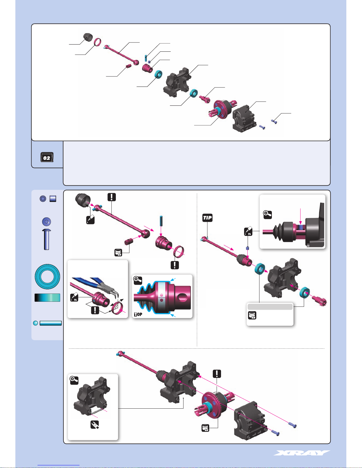
2. FRONT TRANSMISSION
940816
BB 8x16x5
902312
SH M3x12
980314
P 3x14
901404
SB M4x4
Graphite Grease
(HUDY #106210)
Apply oil from inside
to prevent breakage
of the rubber boot.
SHORT CVD DRIVE SHAFT
BEFORE inserting the clip on the central CVD shaft joint, apply a small
amount of threadlock on the area where the clip goes.
AFTER inserting the clip on the central CVD shaft joint, turn the clip so that
the slot is 90°from the pin. This will prevent the pin from opening the clip.
PIN
DETAIL
Cut on both front
and rear bulkhead blocks
DETAIL
➊
➊
➋
➋
➌
➌
➍
➍
STEP DETAIL
➍
STEP
DETAIL
➎
35 2006 DIFF BULKHEAD BLOCK SET FRONT/REAR
35 5003 FRONT/REAR DIFFERENTIAL 46T - SET
35 5114 BEVEL DRIVE GEAR 14T
35 5236 CVD DRIVE SHAFT COUPLING - HUDY SPRING STEEL™
35 5416 CENTRAL CVD SHAFT UNIVERSAL JOINT - HUDY SPRING STEEL™
35 5425 FRONT CENTRAL CVD DRIVE SHAFT - HUDY SPRING STEEL™
35 5471 DRIVE SHAFT LOCKING RING (2)
35 5472 DRIVE SHAFT BOOT (2)
90 1404 HEX SCREW SB M4x4 (10)
90 2312 HEX SCREW SH M3x12 (10)
94 0816 HIGH-SPEED BALL-BEARING 8x16x5 RUBBER SEALED (2)
98 0314 PIN 3x14 (10)
BAG
➎
➎
➎
355003
FRONT DIFF
902312
FRONT DIFF 300.000 cSt
Graphite Grease
(HUDY #106210)
Push joint against gear to remove gap.
Tighten setscrew onto gear flat spot.
The ring can be assembled by hand,
but for easy disassembly we recommend
using snap ring pliers (HUDY #189040)
355472
355471
SHORT
355425
355236
352006
355114
352006
355416
980314
901404
940816
940816
step 1 step 2
step 3
OIL
DETAIL
Follow the TECH TIP on page 5
for drive shaft pin servicing
Use HUDY Ball-Bearing Grease
#106220 - STANDARD
#106221 - BLUE
#106222 - RED
NOTE
ORIENTATION
Page 9
9
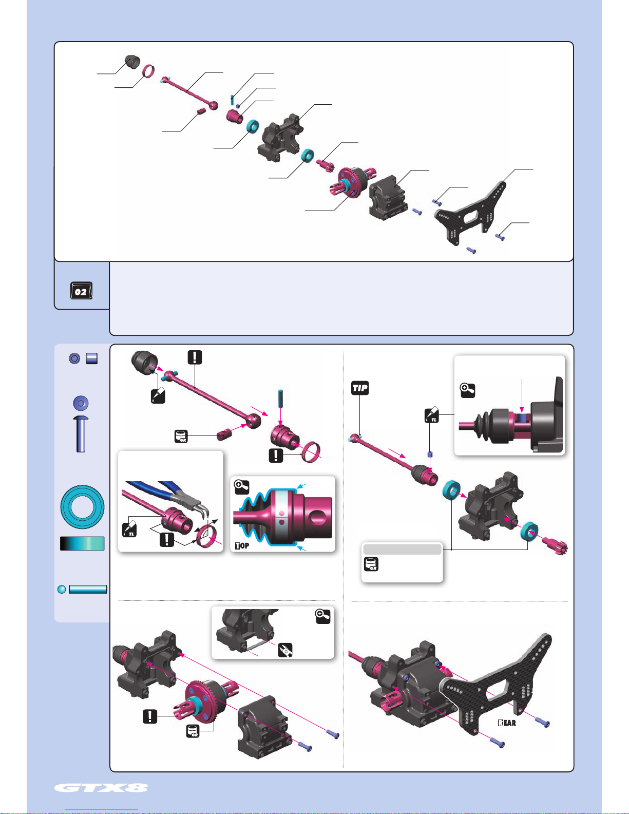
2. REAR TRANSMISSION
940816
BB 8x16x5
902312
SH M3x12
980314
P 3x14
901404
SB M4x4
Apply oil from inside to prevent
breakage of the rubber boot.
Graphite Grease
(HUDY #106210)
NOTE
ORIENTATION
LONG CVD DRIVE SHAFT
Cut on both front and
rear bulkhead blocks
BEFORE inserting the clip on the central CVD shaft joint, apply a small amount of
threadlock on the area where the clip goes.
AFTER inserting the clip on the central CVD shaft joint, turn the clip so that the slot is
90°from the pin. This will prevent the pin from opening the clip.
Follow the TECH TIP on page 5
for drive shaft pin servicing.
DETAIL
DETAIL
DETAIL
BAG
➊
➊
➋
➋
➌
➌
➍
➍
STEP DETAIL
➎
35 2006 DIFF BULKHEAD BLOCK SET FRONT/REAR
35 5003 FRONT/REAR DIFFERENTIAL 46T - SET
35 3040 GT GRAPHITE REAR SHOCK TOWER - CNC MACHINED 3.5 MM
35 5114 BEVEL DRIVE GEAR 14T
35 5236 CVD DRIVE SHAFT COUPLING - HUDY SPRING STEEL™
35 5416 CENTRAL CVD SHAFT UNIVERSAL JOINT - HUDY SPRING STEEL™
35 5640 GT REAR CENTRAL CVD DRIVE SHAFT - HUDY SPRING STEEL™
➎
➎
➎
355003
REAR DIFF
902312
Graphite Grease
(HUDY #106210)
REAR DIFF 60.000 cSt
The ring can be assembled by hand,
but for easy disassembly we recommend
using snap ring pliers (HUDY #189040)
Push joint against gear to remove gap.
Tighten setscrew onto gear flat spot.
902312
355471
355472
LONG
355640
355236
352006
355114
352006
353040
355416
980314
901404
940816
940816
PIN
STEP DETAIL
➍
step 1 step 2
step 3
OIL
35 5471 DRIVE SHAFT LOCKING RING (2)
35 5472 DRIVE SHAFT BOOT (2)
90 1404 HEX SCREW SB M4x4 (10)
90 2312 HEX SCREW SH M3x12 (10)
94 0816 HIGH-SPEED BALL-BEARING 8x16x5 RUBBER SEALED (2)
98 0314 PIN 3x14 (10)
step 4
Use HUDY Ball-Bearing Grease
#106220 - STANDARD
#106221 - BLUE
#106222 - RED
Page 10
10
BAG
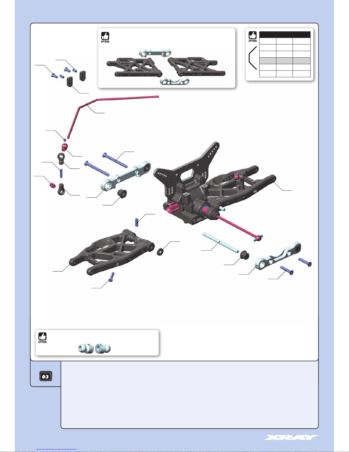
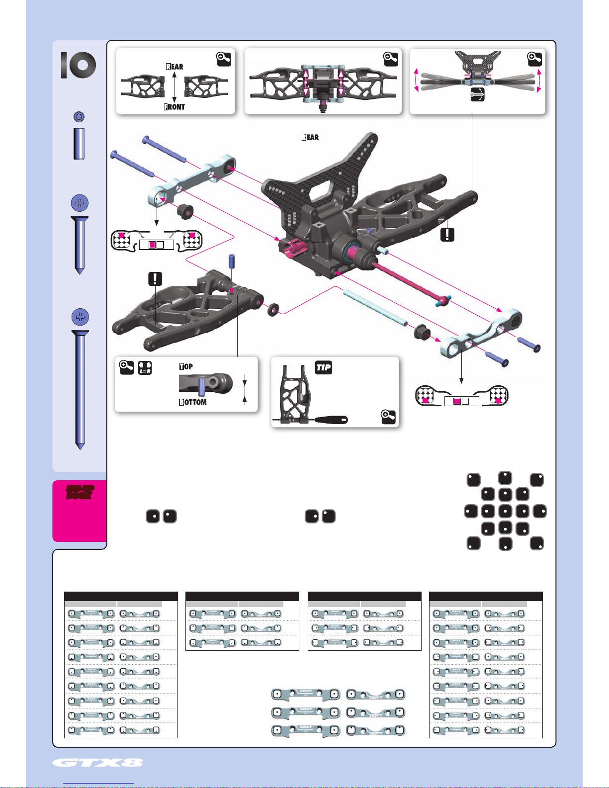
3. REAR SUSPENSION
909395
353426
353371
352006
909372
353317
352314
902318
903308
901305
901303
333450
352470
901312
352470
353123
352460
33 3450 ANTI-ROLL BAR BALL JOINT 5.8 MM (2)
35 2006 DIFF BULKHEAD BLOCK SET FRONT/REAR
35 2314 COMPOSITE ECCENTRIC BUSHINGS - V2 (2)
35 2460 PIVOT BALL 5.8 (10)
35 2470 BALL JOINT 5.8 (8)
35 3113 COMPOSITE REAR LOWER SUSPENSION ARM - RIGHT
35 3123 COMPOSITE REAR LOWER SUSPENSION ARM - LEFT
35 3317 ALU REAR LOWER SUSP. HOLDER - FRONT - SQUARE ADJ. ROLL CENTER
35 3325 ALU REAR LOWER SUSP. HOLDER - REAR - SQUARE ADJ. ROLL CENTER
35 3371 SET OF COMPOSITE LOWER ARM SHIMS
35 3426 REAR ANTI-ROLL BAR 2.6MM
35 7212 LOWER INNER PIVOT PIN F+R (2)
357212
352314
353113
353325
901412
90 1303 HEX SCREW SB M3x3 (10)
90 1305 HEX SCREW SB M3x5 (10)
90 1312 HEX SCREW SB M3x12 (10)
90 1412 HEX SCREW SB M4x12 (10)
90 2318 HEX SCREW SH M3x18 (10)
90 3308 HEX SCREW SFH M3x8 (10))
90 9372 SCREW PHILLIPS SS 3.5x22 (10)
90 9395 SCREW PHILLIPS SS 3.5x45 (10)
REAR ANTI-ROLL BARS
#353422 ø2.2mm OPTION
#353424 ø2.4mm OPTION
#353425 ø2.5mm OPTION
#353426 ø2.6mm INCLUDED
#353428 ø2.8mm OPTION
#353430 ø3.0mm OPTION
#353115 COMPOSITE REAR LOWER SUSPENSION ARM
#353316 ALU REAR LOWER SUSP. HOLDER - FRONT - SQUARE ADJ. ROLL CENTER
#353327 ALU REAR LOWER SUSP. HOLDER - REAR - SQUARE ADJ. ROLL CENTER
#333451
ALU ANTI-ROLL BAR PIVOT BALL 5.8 MM - SWISS 7075 T6 - HARDCOATED (2)
Page 11
11
TOE-IN
ANTI-SQUAT
ROLL CENTER DOWNSTOP
WHEELBASE
TRACK WIDTH
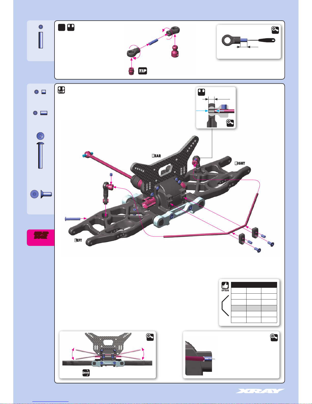
3. REAR SUSPENSION
909395
SS 3.5x45
909372
SS 3.5x22
901412
SB M4x12
353371
SHIM 4x10x2
Check for free movement
REAR ARM ORIENTATION
➊
➊
➋
➌
➌
➍
➍
➎
2mm
4x12mm
RR
RF
All possible mounting
alternatives of eccentric bushings
Push the arm from both sides to create play
INITIAL SETTING
RF
0.5°
1°
INITIAL SETTING
RR
0.5°
1°
DETAIL DETAIL
ECCENTRIC BUSHINGS HAVE TWO DIFFERENT OFFSETS FROM THE CENTER.
Middle position = 0.5 mm or 0.5° from center
Outer position = 1mm or 1° from center
3.5x45mm
3.5x22mm
BOOK
SET-UP
DETAIL
The new XRAY rear alu lower suspension holders provide even greater range of adjustment for the rear suspension. Using different combinations of eccentric bushings, fine adjustment of rear anti- squat, rear
toe-in, rear roll center, and rear track-width can be obtained. For more information about the influence of rear anti-squat, rear toe-in, rear roll center and rear track width on car handling, please refer to HUDY
Off-Road Set-up Book (#209099).
The tables describe the amounts of rear anti-squat, rear toe-in, rear track-width change depending
on the combinations of eccentric bushings used with 0 and 1mm, 1° off set. The 0.5mm, 0.5° represent
the half change.
Example:
0(RR) - 0 (RF) = 3°
0(RR) - 0.5 (RF) = 3.5°
0(RR) - 1 (RF) = 4°
ANTI-SQUAT ROLL CENTER TRACK-WIDTH TOE-IN
RR RR RR RRRF RF RF RF(°) (mm) (mm) (°)
=3°
=4°
=2°
=4°
=3°
=5°
=2°
=3°
=1°
= 3°
= 3.5°
= 4°
=0
mm
=1mm
=-1mm
=308
=306
=310
=3°
=4°
=2°
=2°
=3°
=1°
=4°
=5°
=3°
(HUDY #107634)
If the suspension arm does not move
freely use a HUDY Arm Reamer to
resize the holes of the arms.
DETAIL
ARM REAMER
NOTE
ORIENTATION
NOTE
ORIENTATION
5.5mm
DOWNSTOP SETTING
DETAIL
Page 12
12
3. REAR SUSPENSION
ANTI-ROLL BAR
901303
SB M3x3
901305
SB M3x5
901312
SB M3x12
902318
SH M3x18
903308
SFH M3x8
1.5mm
6mm
DETAIL
-2~0mm
L=R
STEP DETAIL
➍
DETAIL
Loosen the 3x5 setscrew if the
anti-roll bar does not turn freely
Step
➊
DETAIL
Step check for free movement
➊
DETAIL
➋
➊
➌
3x5mm
3x8mm
3x3mm
3x18mm
L=R
2x
Follow the TECH TIP on page 5 to install the pivot balls
BOOK
SET-UP
REAR ANTI-ROLL BARS
#353422 ø2.2mm OPTION
#353424 ø2.4mm OPTION
#353425 ø2.5mm OPTION
#353426 ø2.6mm INCLUDED
#353428 ø2.8mm OPTION
#353430 ø3.0mm OPTION
Page 13
13
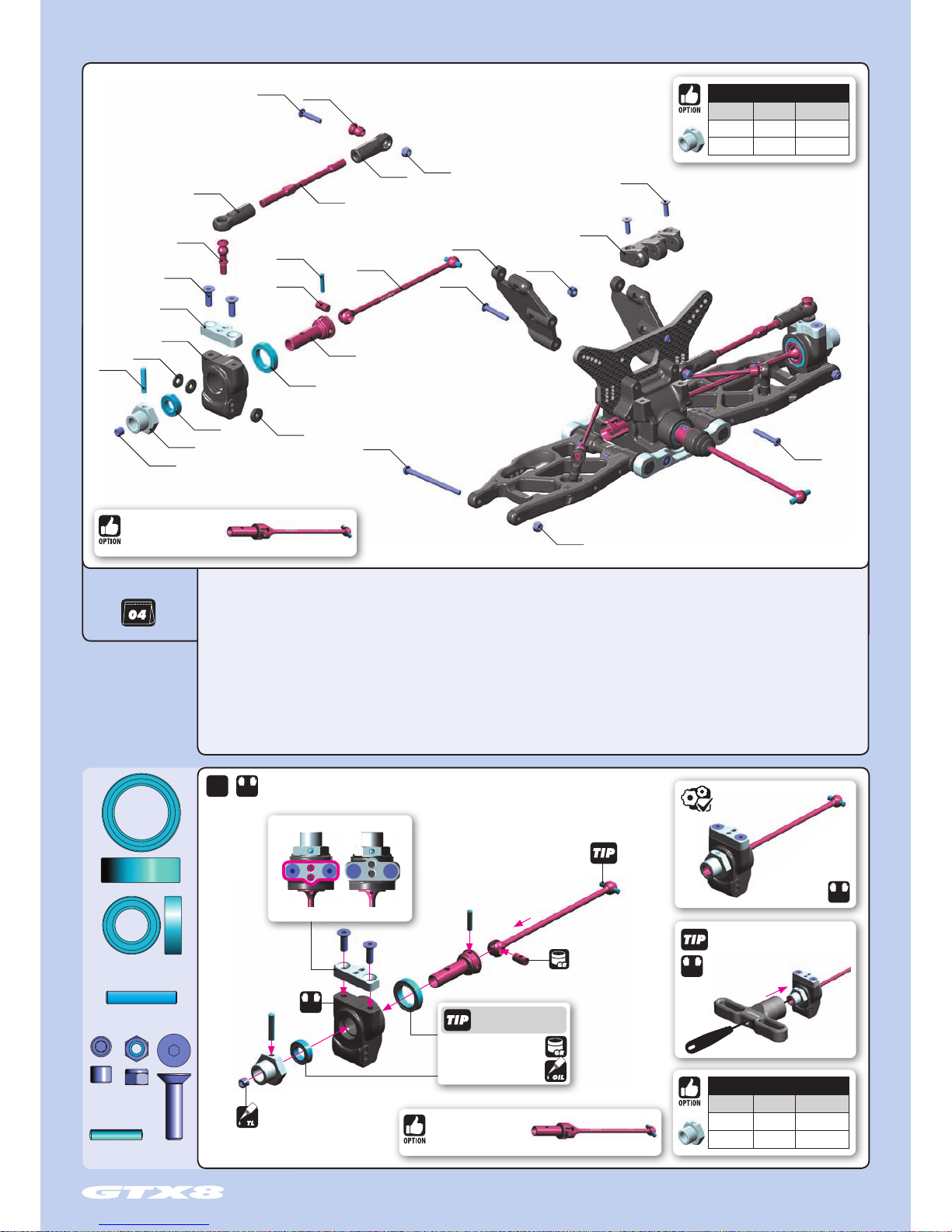
980317
P 3x17
901504
SB M5x4
940814
BB 8x14x4
941319
BB 13x19x4
960030
N M3
980263
P 2.5x13
903416
SFH M4x16
2x
L=R
➊
➋
➌
➍
➑
➐
➒
➏
➍
➎
L=R
Graphite Grease
(HUDY #106210)
INITIAL SETTING
Alternative 01 Alternative 02
3x17mm
2.5x13mm
8x14x4mm
13x19x4mm
Follow the TECH TIP on page
5 for drive shaft pin servicing
Use HUDY Ball-Bearing
Grease or Oil for servicing:
#106220 - Standard
#106221 - Extra
#106222 - Premium
#106230 - Bearing Oil
L=R
To tighten the setscrew you can
also use the HUDY 17mm Wheel
Nut Tool #107570
2.5mm
L=R
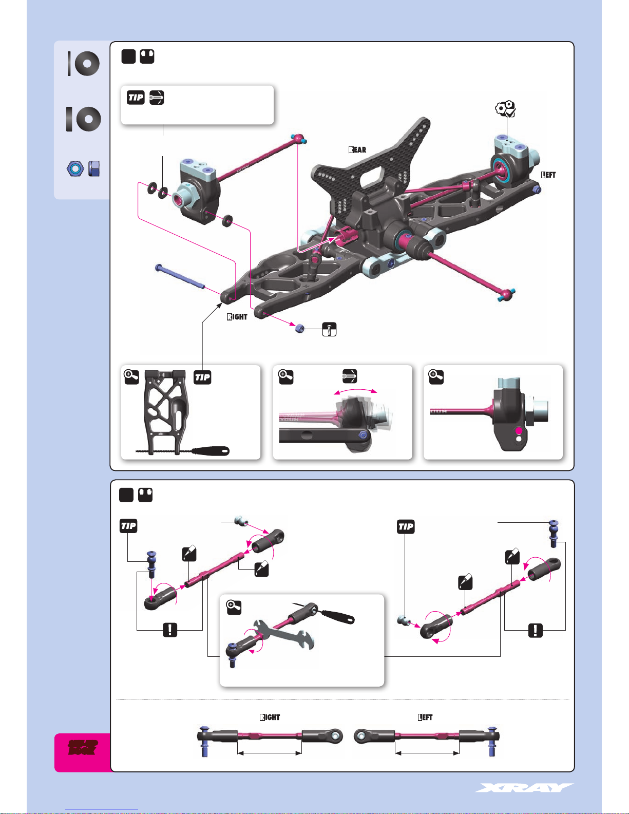
4. REAR SUSPENSION
35 2234 ALU REAR HUB MOUNTING PLATE - SWISS 7075 T6
35 2633 ADJ. TURNBUCKLE M5 L/R 72 MM - HUDY SPRING STEEL™ (2)
35 2657 BALL STUD 6.8MM WITH BACKSTOP L=8MM - M4x6 (2)
35 3020 COMPOSITE REAR BRACE HOLDER
35 3131 REAR UPPER INNER CAMBER LINK BALL JOINT - V3 (2)
35 3160 MOUNTING BALL 6.8 (4)
35 3352 COMPOSITE REAR UPRIGHT
35 3370 SET OF COMPOSITE REAR HUB CARRIER SHIMS
35 3523 GT COMPOSITE REAR HOLDER POST (2)
35 5211 CVD DRIVE AXLE - HUDY SPRING STEEL™
35 5221 CVD UNIVERSAL DRIVE SHAFT - HUDY SPRING STEEL™
35 5237 CVD DRIVE SHAFT COUPLING - HUDY SPRING STEEL™
35 5250 ALU WHEEL AXLE - BLACK COATED (2)
BAG
35 7331 REAR LOWER OUTER PIVOT PIN SCREW 3MM (2)
90 1504 HEX SCREW SB M5x4 (10)
90 2318 HEX SCREW SH M3x18 (10)
90 2320 HEX SCREW SH M3x20 (10)
90 3312 HEX SCREW SH M3x12 (10)
90 3416 HEX SCREW SH M4x16 (10)
94 0814 HIGH-SPEED BALL-BEARING 8x14x4 BLUE COVERED (2)
94 1319 HIGH-SPEED BALL-BEARING 13x19x4 BLUE COVERED (2)
96 0030 NUT M3 (10)
98 0263 PIN 2.5x13 (10)
98 0317 PIN 3x17 (10)
OFFSET WHEEL AXLES
#355250 0mm INCLUDED
#355251 +1mm OPTION
#355252 +2mm OPTION
OFFSET WHEEL AXLES
#355250 0mm INCLUDED
#355251 +1mm OPTION
#355252 +2mm OPTION
357331
902320
903312
902318
353160
353131
980263
355237
355221
352657
903416
352234
353370
353352
980317
960030
353020
353523
902318
960030
960030
353131
352633
355211
941319
353370
940814
355250
901504
#355222
UNIVERSAL DRIVE SHAFT
HUDY SPRING STEEL™ - SET
#355222
UNIVERSAL DRIVE SHAFT
HUDY SPRING STEEL™ - SET
Page 14
14
4. REAR SUSPENSION
CAMBER
353370
SHIM 3x9x1
353370
SHIM 3x9x2
960030
N M3
Follow the TECH TIP on page 5
to install the pivot balls
NOTE ORIENTATION
NOTE ORIENTATION
Right threadLeft thread Right thread Left thread
43.5 mm 43.5 mm
RIGHT
THREAD
RIGHT THREAD
LEFT
THREAD
LEFT THREAD
Follow the TECH TIP on page 5
to install the pivot balls
OIL
OIL
OIL
OIL
INITIAL SETTING
Check for free
movement
DETAILDETAIL
Use tools
to tighten as shown
DETAIL
DETAIL
Ensure that the rear upright moves freely.
If it does not move freely, use sandpaper
to thin both wheelbase adjustment shims.
Shims for wheelbase
adjustment
Do not overtighten the self-locking nut.
Overtightening may result in suspension binding.
2x
L=R
L=R
2x
1mm
2mm
1mm
BOOK
SET-UP
Special Tool for all turnbuckles & nuts (HUDY #181090)
or Turnbuckle Wrench 5mm (HUDY #181050)
(HUDY #107633)
If the suspension arm does
not move freely use a HUDY
Arm Reamer to resize the
holes of the arms.
ARM REAMER
Page 15
15
4. REAR SUSPENSION
353380
SHIM 4x7.5x1
353381
SHIM 4x7.5x2
960030
N M3
902318
SH M3x18
960030
N M3
903312
SFH M3x12
902318
SH M3x18
902320
SH M3x20
DETAIL
INITIAL SETTING
INITIAL SETTING
2x
2x
L=R
L=R
L=R
Optional shims can be used for roll
center adjustment.
#353380 - Alu shim 4x7.5x1mm
#353381 - Alu shim 4x7.5x2mm
3x20mm
3x18mm
Page 16

16
909372
901410
902318
352120
909395
901303
901312
901305
903308
352324
352314
357212
352314
353371
353371
333450
352470
352496
352470
352460
352006
352323
FRONT ANTI-ROLL BARS
#352492 2.2mm OPTION
#352493 2.3mm OPTION
#352494 2.4mm OPTION
#352495 2.5mm OPTION
#352496 2.6mm INCLUDED
5. FRONT SUSPENSION
33 3450 ANTI-ROLL BAR BALL JOINT 5.8 MM (2)
35 2006 DIFF BULKHEAD BLOCK SET FRONT/REAR
35 2120 COMPOSITE FRONT LOWER SUSPENSION ARM
35 2314 COMPOSITE SQUARE ADJ. ROLL CENTER BUSHINGS - V2 (2)
35 2323 ALU FRONT LOWER SUSP. HOLDER - FRONT - SQUARE ADJ. ROLL CENTER - V2
35 2324 ALU FRONT LOWER SUSP. HOLDER - REAR - SQUARE ADJ. ROLL CENTER - V2
35 2460 PIVOT BALL 5.8 (10)
35 2470 BALL JOINT 5.8 (8)
35 2496 FRONT ANTI-ROLL BAR 2.6MM
35 3371 SET OF COMPOSITE LOWER ARM SHIMS
35 7212 LOWER INNER PIVOT PIN F+R (2)
90 1303 HEX SCREW SB M3x3 (10)
90 1305 HEX SCREW SB M3x5 (10)
90 1312 HEX SCREW SB M3x12 (10)
90 1410 HEX SCREW SB M4x10 (10)
90 2318 HEX SCREW SH M3x18 (10)
90 3308 HEX SCREW SFH M3x8 (10))
90 9372 SCREW PHILLIPS SS 3.5x22 (10)
90 9395 SCREW PHILLIPS SS 3.5x45 (10)
BAG
#333451
ALU ANTI-ROLL BAR PIVOT BALL 5.8 MM - SWISS 7075 T6 - HARDCOATED (2)
Page 17

17
5. FRONT SUSPENSION
KICK UP
ROLL CENTER DOWNSTOP
WHEELBASE
TRACK WIDTH
901410
SB M4x10
909395
SS 3.5x45
909372
SS 3.5x22
353371
SHIM 4x10x2
All possible mounting alternatives
of eccentric bushings
3.5x22mm
3.5x45mm
The tables below describe the amounts of kick-up, front track-width change depending on the combinations
of eccentric bushings used with 0 and 1mm, 1° offset. The 0.5mm, 0.5° represents the half change.
TRACK-WIDTH ROLL CENTER
FF FFFR FR(mm) (mm)
=308
=306
=310
=1
=0
=-1
The XRAY alu front lower suspension holders provide even greater range of
adjustment for the front suspension. Using different combinations of eccentric
bushings, fine adjustment of front kick-up, roll center, and front track-width
can be obtained. For more information about the influence of kick-up, front
track-width, and roll centers on car handling, please refer to HUDY Off-Road
Set-up Book (#209099).
Eccentric bushings have two different offsets from the center.
Middle position = 0.5 mm or 0.5° from center
Outer position = 1mm or 1° from center
➊
➊
➋
➌
➌
➍
➍
➎
4x10mm
FR
FF
2mm
2mm
4mm 4mm
4mm 4mm
2mm
2mm
2mm
2mm
DETAIL
FRONT ARM
L=R
DETAIL
Check for free movement
DETAIL
Push the arm from both sides to create play
INITIAL SETTING
FF
0.5°
1°
INITIAL SETTING
FR
0.5°
1°
(HUDY #107634)
ARM REAMER
If the suspension arms do not move freely,
use a HUDY Arm Reamer to resize the holes.
DETAIL
4.2mm
DOWNSTOP SETTING
DETAIL
INITIAL SETTING ALTERNATIVE SETTINGALTERNATIVE SETTING
BOOK
SET-UP
Page 18

18
5. FRONT SUSPENSION
ANTI-ROLL BAR
901303
SB M3x3
901305
SB M3x5
901312
SB M3x12
902318
SH M3x18
903308
SFH M3x8
3x3mm
3x5mm
3x8mm
-2~0mm
3x18mm
L=R
2x
Loosen the 3x5 setscrew if
the anti-roll bar does not
turn freely
Step
➊
➊
➋
➌
➍
L=R
STEP DETAIL
➍
1.5mm
6mm
Follow the TECH TIP on page 5 to
install the pivot balls
DETAIL
DETAIL
DETAIL
Step check for free movement
➊
DETAIL
BOOK
SET-UP
FRONT ANTI-ROLL BARS
#352492 2.2mm OPTION
#352493 2.3mm OPTION
#352494 2.4mm OPTION
#352495 2.5mm OPTION
#352496 2.6mm INCLUDED
Page 19

19
➊
➋
Use HUDY Ball-Bearing
Grease or Oil for servicing:
#106220 - Standard
#106221 - Extra
#106222 - Premium
#106230 - Bearing Oil
35 2132 FRONT UPPER ARM RIGHT
35 2142 FRONT UPPER ARM LEFT
35 2153 FRONT UPPER ARM BALL JOINT (L+R)
35 2240 STEERING BLOCK
35 2376 GT ALU STEERING KING PIN PLATE 0°-7° - SWISS 7075 T6 - L+R
35 2624 ADJ. TURNBUCKLE M5 L/R 38 MM - HUDY SPRING STEEL™ (2)
35 3172 PIVOT BALL 11.0 (2)
35 5211 CVD DRIVE AXLE - HUDY SPRING STEEL™
35 5221 CVD UNIVERSAL DRIVE SHAFT - HUDY SPRING STEEL™
35 5237 CVD DRIVE SHAFT COUPLING - HUDY SPRING STEEL™
35 5250 ALU WHEEL AXLE - BLACK COATED (2)
35 7250 STEEL PIVOT BALL 13.7 MM (2)
Graphite Grease
(HUDY #106210)
2.5mm
To tighten the setscrew you can
also use the HUDY 17mm Wheel
Nut Tool #107570
Follow the TECH TIP on page 5
for drive shaft pin servicing
➎
➍
➍
➏
➐
➑
➌
3x17mm
2.5x13mm
8x14x4mm
13x19x4mm
4x16mm
35 7252 ALU ADJUSTING NUT M15x1 (2)
35 7254 COMPOSITE BALL CUP 13.9 MM (2)
35 7256 ALU SHIM 6x13x1 (2)
90 1504 HEX SCREW SB M5x4 (10)
90 3416 HEX SCREW SFH M4x16 (10)
94 0814 HIGH-SPEED BALL-BEARING 8x14x4 BLUE COVERED (2)
94 1319 HIGH-SPEED BALL-BEARING 13x19x4 BLUE COVERED (2)
98 0263 PIN 2.5x13 (10)
98 0317 PIN 3x17 (10)
980263
901504
SB M5x4
940814
BB 8x14x4
980317
P 3x17
903416
SFH M4x16
980263
P 2.5x13
941319
BB 13x19x4
352376
353172
903416
352153
352376
357256
352624
352153
353172
352240
357250
941319
355211
355237
352132
352142
352624
980317
355250
901504
357254
357252
940814
903416
355221
6. FRONT SUSPENSION
BAG
L=R
2x
#357253
BRASS ADJUSTING NUT M15x1
OFFSET WHEEL AXLES
#355250 0mm INCLUDED
#355251 +1mm OPTION
#355252 +2mm OPTION
OFFSET WHEEL AXLES
#355250 0mm INCLUDED
#355251 +1mm OPTION
#355252 +2mm OPTION
#352235
ALU STEERING KING PIN PLATE 10° - SWISS 7075 T6 - L+R
#352235
ALU STEERING KING PIN PLATE
SWISS 7075 T6 - L+R 10°
#357251
ALU PIVOT BALL 13.7MM WITH STEEL SCREW (2)
#355222
UNIVERSAL DRIVE SHAFT - HUDY SPRING STEEL™ - SET
#355222
UNIVERSAL DRIVE SHAFT
HUDY SPRING STEEL™ - SET
Page 20

20
ROLL CENTER
CAMBER
ROLL CENTER
357256
SHIM 6x13x1
L=R
PIVOT BALLS MUST MOVE FREELY
During initial assembly, tighten each
composite hex nut until the pivot ball
starts to bind, then loosen slightly.
Verify that the pivot balls move freely.
Tighten composite hex nuts
using HUDY tool #107581
2.5mm
353380
SHIM 4x7.5x1
353381
SHIM 4x7.5x2
DETAIL
2.5mm
2.5mm
DETAIL
DETAIL
6. FRONT SUSPENSION
Apply WD40 to
protect against rust
Apply WD40 to
protect against rust
HUDY Tool Allen 2.5mm
30mm
1mm
L=R
L=R
L=R
L=R
2x
2x
2x
2x
2.5mm
SHORT LONG
HUDY Tool Allen Ball 2.5mm
Marked (L) = Marked (L)
106mm106mm
Marked (R) = Marked (R)
DETAIL
INITIAL SETTING
L=R
#357253
BRASS ADJUSTING NUT M15x1
#357251 ALU PIVOT BALL
13.7MM WITH STEEL SCREW (2)
Optional shims can be used for Roll
Center adjustment.
#353380 - Alu shim 4x7.5x1mm
#353381 - Alu shim 4x7.5x2mm
Page 21

21
903412
SFH M4x12
6. FRONT & REAR ASSEMBLY
35 1130 GT ALU CHASSIS - SWISS 7075 T6 (3MM)
35 1232 GT COMPOSITE FRONT & REAR SUSPENSION HOLDER PLATE
35 3083 GT COMPOSITE REAR BRACE
BAG
902325
351232
351130
903412
903412
960030
960040
353083
90 2325 HEX SCREW SH M3x25 (10)
90 3412 HEX SCREW SFH M4x12 (10)
96 0030 NUT M3 (10)
96 0040 NUT M4 (10)
902312
#353281
GT GRAPHITE BRACES FOR REAR COMPOSITE BRACE - SET
960030
353281
353281
Page 22

22
6. FRONT & REAR ASSEMBLY
902325
SH M3x25
903412
SFH M4x12
960030
N M3
960040
N M4
#353281
GRAPHITE BRACE SET for extra stiffness adjustment.
903412
SFH M4x12
M3
M4
NOTE
ORIENTATION
Page 23

23
352664
7. STEERING
30 3122 ALU SHIM 3x6x1.0MM (10)
35 1344 COMPOSITE UPPER PLATE
35 2040 GT GRAPHITE FRONT SHOCK TOWER - CNC MACHINED 3.5 MM
35 2084 COMPOSITE FRONT BRACE
35 2314 COMPOSITE SQUARE ADJ. ROLL CENTER BUSHINGS - V2 (2)
35 2333 ALU FRONT UPPER ARM HOLDER - SWISS 7075 T6 (6MM)
35 2381 CASTER CLIPS (2)
35 2505 SERVO SAVER COMPLETE SET
35 2513 COMPOSITE SERVO SAVER
35 2576 STEERING PLATE BUSHING (2)
35 2579 ALU STEERING PLATE - SWISS 7075 T6
35 2611 ADJ. TURNBUCKLE M4 L/R 52.5 MM - HUDY SPRING STEEL™ (2)
35 2652 BALL STUD 6.8MM (4)
35 2653 BALL STUD 6.8MM WITH BACKSTOP - M3 (2)
35 2664 COMPOSITE STEERING BALL JOINT 6.8MM - V3 (2)
35 2666 COMPOSITE RELIEF STEERING BALL JOINT 6.8MM (2)
35 7222 FRONT UPPER PIVOT PIN 4x45 (2)
BAG
90 2308 HEX SCREW SH M3x8 (10)
90 2310 HEX SCREW SH M3x10 (10)
90 2312 HEX SCREW SH M3x12 (10)
90 3308 HEX SCREW SFH M3x8 (10)
90 3310 HEX SCREW SFH M3x10 (10)
90 3312 HEX SCREW SFH M3x12 (10)
90 3320 HEX SCREW SFH M3x20 (10)
90 3410 HEX SCREW SFH M4x10 (10)
90 3412 HEX SCREW SFH M4x12 (10)
94 0610 HIGH-SPEED BALL-BEARING 6x10x3 BLUE COVERED (2)
96 0030 NUT M3 (10)
96 0040 NUT M4 (10)
96 2041 WASHER S 4x8x0.5 (10)
97 0121 O-RING 12.1 x 1.6 (10)
Must be used also 2pcs of #303136 shim 3x7x1mm.
NOTE
#351348
GRAPHITE UPPER PLATE
352576
352513
902308
352666
357222
357222
960030
352653
352652
903320
960030
960040
352611
352611
903310
903312
903308
940610
352505
352513
352579
902310
352664
352513
352505
352505
970121
940610
352505
903410
903312
351344
352084
352381
352381
962041
352333
352314
352314
902312
902312
352040
903412
352653
902312
303122
303122
352652
352666
960030
903320
BALL STUD 6.8mm WITH BACKSTOP
#352658 L=6MM - M3x8 OPTION
#352659 L=6MM - M3x11 OPTION
#352514
COMPOSITE SERVO SAVER - GRAPHITE
Page 24

24
SERVO SAVER
BOOK
SET-UP
7. STEERING
902308
SH M3x8
940610
BB 6x10x3
903410
SFH M4x10
970121
O 12.1x1.6
4~5mm
INITIAL PRELOAD SETTING
DETAIL
DETAIL
3.0mm
HUDY Tool Allen 3.0mm
NOTE ORIENTATION
DETAIL
For servicing use
Bearing Oil (HUDY #106230)
Page 25

25
ROLL CENTER
903308
SFH M3x8
903312
SFH M3x12
Check for free
movement
After the top deck assembly check for free movement of steering system.
4x12mm
3x12mm
3x10mm
3x10mm
3x12mm
3x12mm
NOTE
ORIENTATION
M3
M4
RIGHT THREAD
RIGHT THREAD
LEFT THREAD
LEFT THREAD
34.7 mm
34.7 mm
LEFT THREAD
RIGHT THREAD
LEFT THREAD
RIGHT THREAD
NOTE
ORIENTATION
NOTE
ORIENTATION
NOTE
ORIENTATION
NOTE
ORIENTATION
NOTE
ORIENTATION
NOTE
ORIENTATION
Follow the TECH TIP on page 5
to install the pivot balls
Special Tool for all turnbuckles & nuts:
(HUDY #181090)
or Turnbuckle Wrench 4mm:
(HUDY #181040)
Use tools to tighten
as shown
DETAIL
7. STEERING
902312
SH M3x12
960030
N M3
All possible mounting
alternatives of eccentric bushings
DETAIL
DETAIL
DETAIL
NOTE ORIENTATION
INITIAL SETTING
0.5°
1°
903412
SFH M4x12
960040
N M4
BOOK
SET-UP
903310
SFH M3x10
DO NOT OVERTIGHTEN SCREWS
Page 26

26
ROLL CENTER
CASTER
ACKERMANN
BUMP STEER
TOE-IN
C
A
S
T
E
R
7. STEERING
F=R
2.0mm
0.5mm
+
1.0mm
UPPER CLIP
LOWER SHIM
Behind arm
Behind arm
960030
N M3
303122
SHIM 3x6x1
L=R
2x
1.0mm
Check for free
movement
Check for free
movement
INITIAL POSITION
902312
SH M3x12
962041
SHIM 4x8x0.5
902310
SH M3x10
NOTE
ORIENTATION
BOOK
SET-UP
BOOK
SET-UP
All possible mounting alternatives of eccentric bushings
0.5°
1°
INITIAL POSITION
Cutaway view
Shock Tower
NOTE
ORIENTATION
DETAIL
CASTER
UPPER CLIP
(Behind arm)
LOWER SHIM (Behind arm)
4mm 2mm 0
3mm 28º 25º 22º
2mm 29.5º 26.5º 23.5º
1mm 31º 28º 25º
0 32.5º 29.5º 26.5º
Clearance shim
The clearance shim 0.5mm can be installed
anywhere and will not affect caster.
Caster shims
Page 27

27
8. CENTER DIFF & BRAKE
BAG
34 5520-O CARRIER FOR 2-SPEED GEAR (2nd) - SWISS 7075 T6 - ORANGE
34 5530 ALU DRIVE FLANGE WITH ONE-WAY BEARING - SWISS 7075 T6
34 5540 COMPOSITE 2-SPEED GEAR BOX SHOE - SET
34 5546 COMPOSITE 2-SPEED GEAR 46T (2nd) - H
34 5549 COMPOSITE 2-SPEED GEAR 49T (1st)
34 5570 ADAPTER 2-SPEED
34 5581 GEAR BOX SPRING C=13.0 (2)
35 4010 CENTER DIFF MOUNTING PLATE - SET
35 4033 GT COMPOSITE 2-SPEED HOLDER PLATE (2)
35 4061 ALU BRAKE CAM POST & ROD (2+2) HARD COATED
35 4110 VENTILATED BRAKE DISK - LASER CUT - PRECISION-GROUND
35 4121 STEEL BRAKE PAD - LASER CUT (4)
35 4130 BRAKE PAD FIBER (4)
35 4210 GT 2-SPEED SHAFT - HUDY SPRING STEEL™
35 4250 GT COMPOSITE 2-SPEED UPPER PLATE
35 4260 GT CENTRAL TRANSM. OUTDRIVE ADAPTER - HUDY SPRING STEEL™
90 1304 HEX SCREW SB M3x4 (10)
90 1305 HEX SCREW SB M3x5 (10)
90 1404 HEX SCREW SB M4x4 (10)
90 2314 HEX SCREW SH M3x14 (10)
90 2316 HEX SCREW SH M3x16 (10)
90 2330 HEX SCREW SH M3x30 (10)
90 3306 HEX SCREW SFH M3x6 (10)
90 3308 HEX SCREW SFH M3x8 (10)
90 3412 HEX SCREW SFH M4x12 (10)
94 0817 BALL-BEARING 8x14x4 FLANGED (2)
95 0814 BALL-BEARING 8x14x4 FLANGED (2)
98 1310 PIN 3x10 (10)
98 3404 ROLLER PIN 4x4 MM (2)
354010
354010
902316
354010
903412
354010
354010
For improved brake efficiency and increased lifespan
use the OPTION brake bads with springs.
#354131
GLUED BRAKE PADS SET-ULTRA EFFICIENT (4)
#354132
BRAKE PAD “SLS” (4)
#354112
LIGHTWEIGHT VENTILATED BRAKE DISK LASER CUT - PRECISION-GROUND (2)
354110
354260
940817
354250
901304
354061
901304
354061
354061
354130
354121
940817
354260
902330
902314
901305
345540
983404
903306
345520-O
345546
950814
903308
903412
345581
902314
902316
354130
354121
901404
981310
354210
354033
345570
983404
950814
903306
345530
345549
354010
903308
354033
901404
354110
345540
901305
345581
354061
903308
GRAPHITE 2-SPEED GEARS
#345645 45T 2ND OPTION
#345646 46T 2ND OPTION
#345647 47T 2ND OPTION
#345648 48T 1ST OPTION
#345649 49T 1ST OPTION
#345650 50T 1ST OPTION
COMPOSITE 2-SPEED GEARS
#345545 45T 2ND OPTION
#345546 46T 2ND INCLUDED
#345547 47T 2ND OPTION
#345548 48T 1ST OPTION
#345549 49T 1ST INCLUDED
#345550 50T 1ST OPTION
Page 28

28
8. CENTER DIFF & BRAKE
902316
SH M3x16
901304
SB M3x4
903308
SFH M3x8
2x
F=R
Fibre pads
together
ROUND HOLE
OVAL HOLE
NOTE ORIENTATION
NOTE ORIENTATION
NOTE
ORIENTATION
NOTE
ORIENTATION
Temporarily insert brake
disk between pads to set
correct gap
0.5 mm
DETAIL
For improved brake efficiency and increased lifespan
use the OPTION brake bads with springs.
#354131
GLUED BRAKE PADS SET-ULTRA EFFICIENT (4)
#354132
BRAKE PAD “SLS” (4)
Roughen steel plates with
sandpaper before gluing fibre pads
CA CA
2x 2x
FIBRE FIBRESTEEL STEEL
NOTE
ORIENTATION
ROUND HOLE
OVAL HOLE
NOTE
ORIENTATION
VIEW
SHORT LONG
DETAIL DETAIL
1.0mm 2.0mm
Page 29

29
2-SPEED TRANSMISSION
901305
SB M3x5
902314
SH M3x14
983404
RP 4x4
903306
SFH M3x6
950814
BB 8x14x4
ARM REAMER
ARM REAMER
➊
➊
➋
➋
➌
➍
➍
➎
➎
Setscrews must
NOT protrude
Top of screw head
should be level with
hole bottom edge
Do not overtighten gap- setting
setscrews. Only tighten until roller
pins contact the center hub.
SHIFT-POINT SCREW
SHOE-GAP SETSCREW
Use HUDY Reamer #107600 to slightly chamfer
the edges on all 3 holes for screws from inside.
Use HUDY Reamer #107600 to slightly chamfer
the edges on all 3 holes for screws from inside.
46
49
8. CENTER DIFF & BRAKE
NOTE ORIENTATION
NOTE ORIENTATION
NOTE ORIENTATION
NOTE ORIENTATION
3x8mm
4x12mm
NOTE ORIENTATION
OF ALL PARTS
903412
SFH M4x12
903308
SFH M3x8
Page 30

30
Before inserting 3x30 long screws,
loosen the four flat-head screws in
the upper plate by 1/2 turn (CCW).
Tighten all screws after assembly.
981310
P 3x10
901404
SB M4x4
ONE WAY LUBE
46
49
940817
BB 8x16x5
8. CENTER DIFF & BRAKE
NOTE
ORIENTATION
NOTE
ORIENTATION
NOTE
ORIENTATION
DETAIL
BEARING OIL
BEARING OIL
NOTE
ORIENTATION
902330
SH M3x30
#354112
LIGHTWEIGHT VENTILATED BRAKE DISK - LASER
CUT - PRECISION-GROUND (2)
Insert brake disk
between brake pads
All screws
NOTE ORIENTATION
OF ALL PARTS
GRAPHITE 2-SPEED GEARS
#345645 45T 2ND OPTION
#345646 46T 2ND OPTION
#345647 47T 2ND OPTION
#345648 48T 1ST OPTION
#345649 49T 1ST OPTION
#345650 50T 1ST OPTION
COMPOSITE 2-SPEED GEARS
#345545 45T 2ND OPTION
#345546 46T 2ND INCLUDED
#345547 47T 2ND OPTION
#345548 48T 1ST OPTION
#345549 49T 1ST INCLUDED
#345550 50T 1ST OPTION
Page 31

31
33 8584 SHIM 5x7x0.2 (10)
34 8516 XCA ALU 7075 T6 HARD COATED PINION GEAR - 16T (1ST)
34 8519 XCA ALU 7075 T6 HARD COATED PINION GEAR - 19T (2ND)
35 1159 CHASSIS SIDE GUARDS L+R
35 3370 SET OF COMPOSITE REAR HUB CARRIER SHIMS
35 8510 GT 2-SPEED CLUTCH BELL - LIGHTWEIGHT
35 8532 FLYWHEEL - HIGH TORQUE
35 8540 FLYWHEEL COLLAR (OPTION)
35 8550 FLYWHEEL NUT - HUDY SPRING STEEL™
35 8555 GT CLUTCH BELL BUSHING - HUDY SPRING STEEL™
35 8564 ALU CLUTCH SHOE - HARD (3)
35 8588 HIGH TORQUE CLUTCH SPRINGS - MEDIUM (3)
35 8606 FUEL TANK 150CC WITH FLOATING FILTER
35 8680 FUEL TANK MOUNTING POST (2)
35 8685 FUEL TANK MOUNTING GROMMET (4)
35 8723 EXHAUST WIRE MOUNT SET
35 8724 ALU ENGINE MOUNT - CNC MACHINED (L+R)
35 8731 EXHAUST MOUNTING WIRE - LONG
BAG
9. FUEL TANK & ENGINE
35 8941 COMPOSITE TUBING HOLDER FOR FUEL TANK (2)
35 9050 CLUTCH BELL BALL-BEARING 5x10x4 (2)
35 9051 CLUTCH BELL BALL-BEARING 5x12x4 (2)
90 1405 HEX SCREW SB M4x5 (10)
90 2305 HEX SCREW SH M3x5 (10)
90 2316 HEX SCREW SH M3x16 (10)
90 3310 HEX SCREW SFH M3x10 (10)
90 3410 HEX SCREW SFH M4x10 (10)
90 6206 SCREW PHILLIPS FH 2.2x6 (10)
90 8312 HEX SCREW (CAP HEAD) 3x12 (10)
90 8314 HEX SCREW (CAP HEAD) 3x14 (10)
91 1410 HEX SCREW FLANGED SH M4x10 (10)
96 1032 WASHER S 3.2 (10)
96 4073 WASHER S 7x10x0.2 (10)
96 4074 WASHER S 7x10x0.3 (10)
96 4075 WASHER S 7x10x0.5 (10)
903310
358680
358685
348519
Engine
(NOT INCLUDED)
358564
338584
908314
348516
358550
358724
911410
358731
351159
351159
358723
358540
(OPTION)
908312
902316
906206
358941
Manifold
(NOT INCLUDED)
Exhaust Pipe
(NOT INCLUDED)
Screw
(NOT INCLUDED)
358555
903410
901405
961032
902305
902305
961032
359050
358510
358588
359051
358532
353370
358606
964073 / 964074 / 964075
CLUTCH SHOE
#358561 ALU - LIGHT (3) OPTION
CLUTCH SPRING
#358584 MEDIUM (3) OPTION
#358585 HARD (3) OPTION
HIGH TORQUE CLUTCH SPRING
#358587 GOLD SOFT OPTION
#358588 GRAY MEDIUM INCLUDED
#358589 SILVER HARD OPTION
HIGH TORQUE CLUTCH SHOE
#358562 ALU - H-TORQUE (3) OPTION
#358563 GRAPHITE (2) OPTION
#358564 ALU - HARD (3) INCLUDED
#358605
FUEL TANK 125CC WITH
FLOATING FILTER
#353250
GRAPHITE BRACE FOR CHASSIS
SIDE GUARDS - SET
1ST PINION GEAR XCA HARD COATED
#348515 15T OPTION
#348516 16T INCLUDED
#348517 17T OPTION
#348518 18T OPTION
2ST PINION GEAR XCA HARD COATED
#348519 19T INCLUDED
#348520 20T OPTION
#348521 21T OPTION
Page 32

32
7x10x0.2 / 0.3 / 0.5
Use appropriate shims to achieve proper
clutchbell endplay
All screws
Use the cone included with your engine,
or use OPTION XRAY cone #358540
NOTE ORIENTATION
IMPORTANT!
When installing the engine, first check that the drive shaft does not
touch the engine. If it does, remove some material from the engine
mount as shown to make some room between engine and shaft.
908312
SCH M3x12
964073
S 7x10x0.2
964074
S 7x10x0.3
964075
S 7x10x0.5
9. FUEL TANK & ENGINE
902305
SH M3x5
961032
S 3.2
Threadlock on all screws
Threadlock on all screws
Page 33

33
GEARING
GEAR MESH ADJ.
CLUTCH SPRINGS
CLUTCH SHOE
911410
SHF M4x10
THREAD LOCK
all screws
Adjust gear mesh so there is minimal
play between the gears.
Too tight gear mesh will put excessive
strain on all parts and damage the
parts. Too loose gear mesh may result
in stripped gears.
9. FUEL TANK & ENGINE
NOTE: The fuel tank insert can be easily mounted to the bottom of the fuel tank using the provided screw, when the fuel tank cap is opened fully.
2cc
NOTE ORIENTATIONNOTE ORIENTATION
1cc
Tube holders are easily connected to the fuel tank by screws. Using screws is much more secure than using glue to attach the holders to the fuel tank.
The larger insert decreases the fuel tank volume by 2cc,
and is recommended for use when the fuel filter is used.
The smaller insert decreases the fuel tank volume by 1cc.
1CC FUEL TANK INSERT2CC FUEL TANK INSERT
The fuel tank has the larger fuel volume and includes OPTIONAL tank inserts for decreasing the volume of the tank. Using the inserts allows
you to adjust the volume of fuel inside the tank; this works in conjunction with variables such as fuel filter capacity and/or length of fuel line to
ensure you have the legal fuel volume limit for racing.
5x12x4mm
5x10x4mm
16T
19T
908314
SCH M3x14
359050
BB 5x10x4
359051
BB 5x12x4
338584
S 5x7x0.2
These bearings must still be regularly
serviced and replaced when worn out.
Note the orientation of
the clutch shoes. The
short side of spring
must be in the groove
of the flywheel nut.
DETAIL
DETAIL
GEAR MESH
907258
SP 2.5x8
BOOK
SET-UP
BOOK
SET-UP
Tighten the clutch nut using
HUDY tool #107581
Hold the flywheel using
HUDY Flywheel Tool #182015
11~11.2 mm
CLUTCH SHOE
#358561 ALU - LIGHT (3) OPTION
CLUTCH SPRING
#358584 MEDIUM (3) OPTION
#358585 HARD (3) OPTION
HIGH TORQUE CLUTCH SPRING
#358587 GOLD SOFT OPTION
#358588 GRAY MEDIUM INCLUDED
#358589 SILVER HARD OPTION
HIGH TORQUE CLUTCH SHOE
#358562 ALU - H-TORQUE (3) OPTION
#358563 GRAPHITE (2) OPTION
#358564 ALU - HARD (3) INCLUDED
1ST PINION GEAR XCA HARD COATED
#348515 15T OPTION
#348516 16T INCLUDED
#348517 17T OPTION
#348518 18T OPTION
2ST PINION GEAR XCA HARD COATED
#348519 19T INCLUDED
#348520 20T OPTION
#348521 21T OPTION
TO TIGHTEN THE 16T OR 19T PINION GEAR
USE THE OPTIONAL #349901 XRAY PINION
TOOL (19~21T / 16~18T).
Page 34

34
353370
SHIM 3x9x2
9. FUEL TANK & ENGINE
Cut away for
muffler outlet
Bend the exhaust wire as
appropriate to fit the muffler
After running your engine, apply
(#106250 HUDY ENGINE AFTER RUN OIL)
ALTERNATIVE 150CC FUEL TANK ALTERNATIVE 125CC FUEL TANK
INITIAL SETTING
#358605
FUEL TANK 125CC WITH FLOATING FILTER
Not included
902316
SH M3x16
901405
SB M4x5
903410
SFH M4x10
903310
SFH M3x10
906206
SFP 2.2x6
3x10mm
3x10mm
3x16mm
3x16mm
2.2x6mm
3x9x2mm
3x9x2mm
DETAIL
DETAIL
DETAIL
Page 35

35
902312
SH M3x12
10. RADIO CASE
10
BAG
30 2611 ADJ. TURNBUCKLE L/R 35 MM - HUDY SPRING STEEL™ (2)
30 6310 ANTENNA TUBE (2)
33 6120 COMPOSITE STEERING SERVO HOLDER - SET - V2
35 2460 PIVOT BALL 5.8 (10)
35 2670 SERVO BALL JOINT 5.8MM (4)
35 6004 COMPOSITE RADIO CASE SET - SOFT
35 6050 BATTERY CABLE WITH SWITCH (OPTION)
35 6120 STEERING SERVO MOUNT - SET
LEFT THREAD
RIGHT THREAD
Follow the TECH TIP on page
5 to install the pivot balls
HUDY ALU SERVO HORNS
#293501 23T KO Propo, Airtronics, Sanwa OPTION
#293502 24T Hitec OPTION
#293503 25T Futaba OPTION
Use appropriate servo arm:
K - (23T)
H - (24T)
F - (25T)
35 6200 BRAKE/THROTTLE ARMS & STEERING SERVO ARMS - SET
38 9135 CONNECTING CABLE RECEIVER/BATT. PACK (OPTION)
90 2306 HEX SCREW SH M3x6 (10) (OPTION)
90 2310 HEX SCREW SH M3x10 (10)
90 2312 HEX SCREW SH M3x12 (10)
90 2314 HEX SCREW SH M3x14 (10)
90 3412 HEX SCREW SFH M4x12 (10)
96 0030 NUT M3 (10)
The length of the linkages varies
according to the type of servo.
approx. 19.5mm
LEFT THREADRIGHT THREAD
DETAIL
NOTE
ORIENTATION
Receiver battery
(NOT INCLUDED)
Servo Grommet
(NOT INCLUDED)
306310
356004
356004
902310
902312
902310
902306
(NOT INCLUDED)
356004
356004
356004
903412
903412
902314
336120
356120
902314
356120
336120
Throttle Servo
(NOT INCLUDED)
Steering Servo
(NOT INCLUDED)
Servo Grommet
(NOT INCLUDED)
Servo Screw
(NOT INCLUDED)
Receiver
(NOT INCLUDED)
356200
960030
352670
352460
352460
902314
902312
302611
Personal transponder
(NOT INCLUDED)
Page 36

36
907206
SP M2x6
903412
SFH M4x12
960030
N M3
902314
SH M3x14
902310
SH M3x10
902312
SH M3x12
902314
SH M3x14
10. RADIO CASE
Use foam to cushion the
inside of the radio case so
the receiver and battery
cannot vibrate or move.
Plug the connectors into
the receiver in Step 2
Use the shims only if the
servo is too high and
extends from the case
NOTE
NOTE
ORIENTATION
SWITCH #356050
When receiver switch is
used, use hobby knife to
CAREFULLY remove the
material from the cover
and mount the switch.
CUT
2x6
3x10mm
3x10mm
3x12mm
3x14mm
4x12mm
3x6mm (NOT INCLUDED)
Servo screw (NOT INCLUDED)
Personal transponder (NOT INCLUDED)
#902306 Screws (NOT INCLUDED)
Personal transponder can be placed on
the top of the radio box or inside of the
radio box
ALTERNATIVE 1
When the transponder is placed at
the top of the radio box, cut out some
material from the radio box in order
to allow the transponder wire to come
inside.
ALTERNATIVE 2
Place the transponder inside of the
radio box by using double-sided tape.
.........................................
step 1
step 2
Note orientation of servo arm when servo is at neutral
DETAIL
Page 37

37
BAG
11
35 2460 PIVOT BALL 5.8 - V3 (10)
35 8019 COMPOSITE SET OF SHIMS FOR SHOCKS - V2 (2)
35 8020 COMPOSITE SHOCK PARTS
35 8032 SHOCK PISTON SET 8-HOLE (1.2; 1.3) 10-H. (1.1MM) - DELRIN - V2
35 8033 COMPOSITE SHOCK 6-HOLE PISTON SET (1.2; 1.3; 1.4MM) - DELRIN - V2
35 8040 HARDENED SHOCK SHIMS (4)
35 8041 STEEL SHOCK BUSHING (2)
35 8042 COMPOSITE SHOCK BUSHING & SHIM - V2 (2+2)
35 8053 ALU SHOCK CAP NUT - BLACK COATED (2)
35 8084 SHOCK RUBBER MEMBRANE BOTTOM RIBBED (4)
35 8130 GT ALU SHOCK BODY - HARD COATED (2)
35 8142 ALU SHOCK BODY NUT FOR SHOCK BOOT (2)
11. SHOCK ABSORBERS
35 8150 ALU SHOCK BODY ADJ. NUT (2)
35 8163 GT SHOCK SHAFT (2)
35 8196 XRAY GT SPRING - 3 DOTS (2)
96 0026 NUT M2.5 - SHORT (10)
97 0100 O-RING 10 x 1.5 (10)
97 0180 O-RING 18 x 1.8 (10)
97 1034 SILICONE O-RING 3.5x2 (10)
#358054
XB8 ALU SHOCK CAP NUT WITH
VENT HOLE - BLACK COATED (2)
358041
358163
352460
358042
358042
358084
960026
358040
358130
970100
971034
970180
358019
358142
358150
358196
358053
358032
358033
358020
10 holes/ø1.1mm
6 holes/ø1.2mm
8 holes/ø1.2mm
6 holes/ø1.4mm
8 holes/ø1.3mm
6 holes/ø1.3mm
DETAIL
PISTONS
Page 38

38
SHOCK DAMPING
SHOCK PISTONS
960026
N M2.5
358040
S 2.5x6x0.5
There are two different thickness shims, use
them as shown. Use the same procedure
when building both front and rear shocks.
CORRECT
TIGHTEN GENTLY
The self-locking nut is gently tightened.
The piston remains undistorted and fits
inside the shock body perfectly, ensuring
smooth movement of the piston.
INCORRECT
DO NOT OVERTIGHTEN
The self-locking nut is overtightened,
causing distortion of the piston. This will
negatively affect the free movement of
the piston in the shock body.
11. SHOCK ABSORBERS
EXTREMELY IMPORTANT
Do not push the shock rod straight
through the lower shock body
assembly; O-ring damage may result.
Twist the shock rod through the
lower shock body assembly.
INCORRECT
CORRECT
6 holes
ø1.2mm pistons
NOTE ORIENTATION
CORRECT
INCORRECT
INCORRECT
Grip the shock rod at top of exposed
threads with side cutting pliers. Be
careful not to damage the shock rod.
971034
O 3.4x2
970100
O 10x1.5
DETAIL
O-ring
Thin Shim
O-ring
Thick Shim
DETAIL
DETAIL DETAIL
BOOK
SET-UP
4x
4x
4x
Page 39

39
SHOCK OIL
Gently push the shock shaft
completely into the shock
body. Excess oil will flow
through the hole in the
shock cap.
Keep the shock shaft
pushed in the shock body
and tighten the shock cap
completely.
The rebound will be at
approximately 0%.
➐
HALF TIGHTEN TIGHTEN FULLY
100%
Follow the steps below to set the shock rebound to the default setting of 0%.
970180
O 18x1.8
11. SHOCK ABSORBERS
SHOCK
Oil 1000cSt
Extend the shock shaft
completely. Fill the shock
body with the shock oil. For
the shocks use 1000cSt oil.
Move the shock shaft up and
down a few times to release
the air bubbles trapped
beneath the piston.
Orient the filled shock
vertically for several
minutes with the shock
shaft fully extended. The
remaining air bubbles will
release.
Install the shock membrane
into the groove in the
upper shock cap.
Gently place the shock cap
assembly onto the filled
shock body. Excess oil will
spill from the shock. Screw
the shock cap onto the
body by only a few turns.
➊ ➋ ➌ ➍ ➎ ➏
3~5x
UP & DOWN
50%
DEFAULT SHOCK REBOUND SETTING 0% (LOW REBOUND)
DETAIL
Grip the shock rod at top of exposed
threads with side cutting pliers. Be
careful not to damage the shock rod.
INCORRECT
INCORRECT
CORRECT
DETAIL
DETAIL
1 mm
3 mm
DETAIL
BOOK
SET-UP
4x
4x
4x
2x
2x
Page 40

40
Fill the shock body with shock
oil up to the top. Make sure to
use same viscosity shock oil as
is in the shock.
➋
Orient the filled shock
vertically for several minutes
with the shock shaft fully
extended. The remaining air
bubbles will release.
Gently place the shock cap
assembly onto the filled shock
body. Excess oil will spill from
the shock.
➌
➍
50%
HALF TIGHTEN
Push the shock shaft 50% into
the shock body. Excess oil will
bleed thgrough the hole in the
shock cap.
Keep the shock shaft pushed
50% into the shock body
and tighten the shock cap
completely.
The rebound will be at
approximately 50%.
➍
Gently place the shock cap assembly onto the filled
shock body. Keep the shock shaft extended 100% from
the shock body and tighten the shock cap completely.
The rebound will be at approximately 100%.
➎ ➏
TIGHTEN FULLY
100%
50%
The default shock rebound setting is 0% (as described on page 40).
Alternatively, you may set the shock rebound setting to 50% or 100% as described below. Remove the shock springs before performing shock rebound adjustment.
Fill the shock body with shock oil up to the top.
Make sure to use same viscosity shock oil as is
in the shock.
➋
Orient the filled shock vertically for several
minutes with the shock shaft fully extended.
The remaining air bubbles will release.
➌
TIGHTEN FULLY
100%
50%
100%
SETTING THE SHOCK REBOUND TO 50% (MEDIUM REBOUND)
11. SHOCK ABSORBERS
➊
Extend the shock shaft completely
and remove the shock cap.
REMOVE SHOCK CAP
SETTING THE SHOCK REBOUND TO 100% (HIGH REBOUND)
ALTERNATE SHOCK REBOUND SETTING (50% AND 100%)
➊
Extend the shock shaft completely and remove
the shock cap.
REMOVE SHOCK CAP
SHOCK PRELOAD
approx. 3.0mm
approx. 5.0mm
DETAIL
SPRING RATE SHOCK
PRELOAD
RIDE HEIGHT
BOOK
SET-UP
4x
2x
2x
971034
O 3.4x2
Page 41

41
960030
902325
358047
960030
349400
902318
REAR
SHOCK
FRONT
SHOCK
901306
351430
351420
351420
12
BAG
30 2291 STEEL STEERING BUSHING (2+2)
30 2630 ADJ. TURNBUCKLE L/R 20 MM - HUDY SPRING STEEL™ (2)
30 2663 COMPOSITE BALL JOINT 4.9MM - OPEN - V2 (8)
30 3123 ALU SHIM 3x6x2.0MM (10)
34 9400 BODY CLIP (10)
35 1201 GT COMPOSITE FRONT BUMPER
35 1210 GT COMPOSITE FRONT UPPER BUMPER
35 1220 GT FOAM BUMPER
35 1232 GT COMPOSITE FRONT & REAR SUSPENSION HOLDER PLATE
35 1240 GT COMPOSITE FRONT UPPER BUMPER BRACE
35 1410 GT COMPOSITE FRONT HOLDER FOR BODY POSTS
35 1420 GT COMPOSITE BODY POSTS (2)
35 1430 GT COMPOSITE REAR HOLDER FOR BODY POSTS
35 1450 GT COMPOSITE CENTER BODY POST HOLDER
35 5261 WHEEL NUT - RIBBED - HARD COATED (2)
35 6200 BRAKE/THROTTLE ARMS & SERVO ARMS - SET
35 6402 XB8 BRAKE/THROTTLE SYSTEM - SET
35 6433 GT COMPOSITE BRAKE WIRE HOLDER (2)
35 6510 CLOSED BALL JOINT 3.9 (4)
35 8047 STEEL SCREW SHOCK PIVOT BALL WITH HEX (2)
35 8811 AIR FILTER ELBOW - LOW PROFILE
35 8821 AIR FILTER BODY & CAP - LOW PROFILE
35 8841 AIR FILTER FOAM & OIL - LOW PROFILE
35 8950 SILICONE TUBING 1M (2.4 x 5.5MM)
36 2280 ALU CONICAL SHIM 3x6x2.0MM (10)
36 2651 BALL END 4.9MM WITH THREAD 8MM (2)
36 2652 BALL END 4.9MM WITH THREAD 10MM (2)
90 1303 HEX SCREW SB M3x3 (10)
90 1306 HEX SCREW SB M3x6 (10)
90 2308 HEX SCREW SH M3x8 (10)
90 2310 HEX SCREW SH M3x10 (10)
90 2312 HEX SCREW SH M3x12 (10)
90 2314 HEX SCREW SH M3x14 (10)
90 2316 HEX SCREW SH M3x16 (10)
90 2318 HEX SCREW SH M3x18 (10)
90 2319 HEX SCREW SH M3x18 - LEFT THREAD (10)
90 2325 HEX SCREW SH M3x25 (10)
90 3414 HEX SCREW SFH M4x14 (10)
90 3416 HEX SCREW SFH M4x16 (10)
96 0030 NUT M3 (10)
96 0040 NUT M4 (10)
96 1022 WASHER S 2.2 (10)
12. FINAL ASSEMBLY
#358832
AIR FILTER RAIN COVER
WHEEL NUTS
#355261 OPEN INCLUDED
#293560 COVERED OPTION
#355265 COVERED OPTION
902319
358047
960030
349400
351420
902316
349400
901303
901306
351410
362651
960040
902310
349400
351420
351450
901306
351220
351201
903414
903414
302291
902312
356200
356433
351420
351240
351210
901306
351420
960030
903414
351232
356510
358811
356402
356402
901303
903416
901303
356402
961022
961022
356402
356402
901303
356402
356402
901303
358950
358950
302663
960030
356402
358841
358821
358821
356402
358950
902310
902314
356402
358841
Wheel & Tire
(NOT INCLUDED)
355261
902308
4x
#359730 XRAY GT BODY
(NOT INCLUDED)
302630
362652
303123
362280
Page 42

42
SHOCK ABSORBERS
BOOK
SET-UP
SHOCK ABSORBERS
960030
N M3
960030
N M3
902319
SH M3x18
LEFT thread
902318
M3x18
901303
SB M3x3
902314
SH M3x14
SHORTER
LONGER
SHORTER
LONGER
On the front right arm use the SILVER M3x18
screw - this screw has LEFT THREAD
Use STANDARD
M3x18 screw
3x18mm
L=R
L=R
2x
2x
902319
SH M3x18
LEFT thread
960030
N M3
902318
SH M3x18
12. FINAL ASSEMBLY
On the rear left arm use the SILVER M3x18
screw - this screw has LEFT THREAD
Use STANDARD
M3x18 screw
M3x18mm
INITIAL SETTING
DETAIL
L=R
BOOK
SET-UP
DETAIL
L=R
INITIAL SETTING
NOTE
ORIENTATION
NOTE
ORIENTATION
INITIAL SETTING
DETAIL
L=R
Throttle rod
Thread brake rods into plastic
pivots until flush with outer end
Brake rod
Brake rod
Cut off remaining
material
Use servo horn to
match your servo
K
- (23T)
H - (24T)
F - (25T)
HUDY ALU SERVO HORNS
#293504 23T KO Propo, Airtronics, Sanwa OPTION
#293505 24T Hitec OPTION
#293506 25T Futaba OPTION
#293507 23T KO Propo, Airtronics, JR OPTION
#293508 24T Hitec OPTION
#293509 25T Futaba OPTION
INITIAL SETTING
DETAIL
L=R
The lower shock position
can not be used.
Page 43

43
901303
SB M3x3
961022
S 2.2
Servo screw
(NOT INCLUDED)
Ensure that the servo is in neutral position
before attaching the servo horn
3x12mm
3x6mm
3x6mm
4x14mm
4x16mm
M3
M4
➊ Remove the screws from mounting plate and servo horn
➋ Install the servo brace
➌ Check free move
3x6x2mm
3x6x2mm
NOTE ORIENTATION
CONICAL SHIM
8mm THREAD
10mm THREAD
8mm THREAD
10mm THREAD
NOTE
ORIENTATION
4.3mm
303123
SHIM 3x6x2
362280
CON. SHIM 3x6x2
SILICONE
TUBING
8mm
DETAIL
901306
SB M3x6
902312
SH M3x12
902316
SH M3x16
903414
SFH M4x14
903416
SFH M4x16
12. FINAL ASSEMBLY
NOTE
ORIENTATION
NOTE
ORIENTATION
3x16mm
Page 44

44
902310
SH M3x10
960030
N M3
12. FINAL ASSEMBLY
WHEEL NUTS
#355261 OPEN INCLUDED
#293560 COVERED OPTION
#355265 COVERED OPTION
Wheel & Tire
(NOT INCLUDED)
Wheel & Tire
(NOT INCLUDED)
4x
902325
SH M3x25
To tighten the screw you can also use the
#107570 HUDY 17mm Wheel Nut Tool
Cut off remaining
material
Cut off remaining
material
➐
approx. 52mm
approx. 37mm
NOTE
ORIENTATION
NOTE
ORIENTATION
DETAIL
NOTE
ORIENTATION
901306
SB M3x6
901306
SB M3x6
Page 45

45
➍
Before cutting and making holes on the body, put the unpainted body on the chassis to confirm the
mounting position and location for holes and cutouts.
Before painting, wash the inside of the body with mild detergent, and then rinse and dry thoroughly.
Mask all windows.
Apply paint masks as appropriate.
➊
➋
➌
Paint the body using paints formulated for polycarbonate bodies.
When the paint is dry, remove the masking.
Carefully cut out the body using appropriate scissors or cutting tools.
When you have finished cutting, peel off the external protective films.
➎
➏
➐
➑
12. FINAL ASSEMBLY
Cut the silicone tube depending on engine and muffler. Use the plastic clips to hold the tubes together.
SILICONE TUBE MARKED AS
BLUE = FROM FUEL TANK TO CARBURETOR
SILICONE TUBE MARKED AS
RED = FROM MUFFLER TO FUEL TANK (TOP)
Keep fuel line away from
clutchbell and flywheel.
902308
SH M3x8
Apply #106240 HUDY air filter oil
and follow the engine instructions
to service the air filter.
#358832
AIR FILTER RAIN COVER
#359730 GTX BODY (NOT INCLUDED)
Use Body Reamer (HUDY #107600)
for all holes.
To reinforce the body or to fix broken
body use #106280 HUDY BODY FIX
353565
903308
M3x8
960030
M3
309319
3x7x1
WING SHIMS
#353565 COMPOSITE INCLUDED
#293561 ALU OPTION
#293561-O ALU OPTION
#353561 ALU OPTION
Page 46

46
• Never modify the engine or muffler.
• Confirm the position of needle and idling before running. Be sure to run a new engine smoothly.
• Make sure the air filter is clean and oiled.
• Never run your engine without an air filter. Your engine can be seriously damaged if dirt and debris
get inside the engine.
• For proper engine break-in, please refer to the manual that came with the engine.
• The engine may not start or run properly if the air filter is dirty, or choked with sand and dust.
• If the fuel pipe is choked or deteriorates, the engine may not start, and there is danger that fuel will
leak out.
1. Make sure the transmitter and receiver batteries are fully charged.
2.
Make sure that your transmitter and receiver are both on the same frequency. If you have a
transmitter with multiple model memory, make sure you have selected the proper profile for your car.
3. Put the car on the starter box and keep the tires from touching the ground.
4. Turn on the transmitter.
5. Turn on the receiver in the car.
6. Make sure the steering servo and engine servos work normally and adjust them correctly.
7. Put fuel in the fuel tank, and close the cap securely.
8. Apply the glow igniter to the engine glowplug.
9. Push the model car onto the starter box to start the engine. (If the engine is new, follow the instruction
manual and be sure to break in the new engine properly).
10. When the engine has started, remove the glow igniter.
11. Follow your engine break-in procedure and tune the engine as appropriate.
STARTING AND RUNNING THE ENGINE
Be sure to observe the following starting process. Failure to do so may cause the model car to start suddenly, which may lead to damage or unexpected accidents.
STOPPING THE ENGINE
Before you stop the engine, try to make sure the engine is at idle first. There are several ways to stop the engine:
•
Use a rag to cover the exhaust tip. Be careful! The exhaust is extremely hot so use a thick rag and gloves.
• Pinch the fuel tubing to stop the flow of fuel to the carb. Be careful, this can make the motor run lean
which can damage the motor.
• Put your hand over the air filter, or squeeze the air filter element to block the airflow.
• Press an object (such as a screwdriver handle or shoe) against the rotating flywheel to stop its
rotation. Be very careful, and do not stick your hand or fingers near the rotating flywheel.
FINISHING OPERATIONS
1. Stop the engine.
2. Turn off the receiver in the car
3. Turn off the transmitter.
MAINTENANCE AFTER RUNNING
Take proper care of your car after running to keep it performing well, and take notice of any damage and wear.
1. Do not leave fuel in the tank.
2. Go outside to drain any residual fuel from the exhaust pipe.
3. Clean the car and remove all sand, mud, and other debris.
4. Use after-run oil in your engine after you have finished running for the day.
• For club racing, it is recommended to check the shocks for air inside before each race and only re-fill
and bleed them if necessary. Before each race day, make sure you take the spring off of each shock,
hold it up to your ear, and quickly compress the shock rod fully into the body while listening for any
air making a “whistling” or “squishy ” sound as it passes through the piston holes. If you hear any
air, refill and bleed your shocks. For high-competition racing, it is recommended that the shocks be
re-filled and bled before a large event.
• If building or pairing new shocks, always make sure they are the same length using a shock length
measuring tool and adjust the lower ball joints as needed.
• If installing new rubber bladders, carefully trim the thin excess rubber from the edges of their lips.
Curved body scissors work the best.
• Regularly inspect the amount of dirt on the felt protector in the shocks (if present) and regularly
replace with a new one.
• During regular shock operation, oil naturally gets on the shock shaft and drop-by-drop slightly gets
out of the shock body. Shocks should be inspected regularly after each race, and oil replaced as
required.
1. Remove the seals on both sides of the bearing (if present). If the seals bend a little and you can see
a kink, carefully flatten the kink out by hand.
2. Spray the seals with motor cleaner and blow dry with compressed air.
3. Spray the bearing on both sides with motor cleaner.
4. Spin the bearing while it is still wet to dislodge any particles with the cleaner.
5. Spray the bearing on both sides again.
6. Blow both sides of the bearing dry with compressed air to make sure particles come out.
7. Hold the inner part of the bearing with my left thumb/forefinger and spin it to make sure it spins free
without any abnormal vibrations or sounds.
8. Place one drop of bearing oil into each side of the bearing.
9. Replace both seals at the same time by lining them up on each side of the bearing and lightly pressing them in all the way around the bearings circumference with your thumb and forefinger. Do not
press too hard or use any type of tool, such as a wrench tip, to push the blue seals in as they will push
in too far, bend and cause drag.
If you spin test the bearing after you have re-oiled and sealed it, it will not spin freely for an extended period of time. The lightest of oils may allow it to spin for 1-2 seconds. This is normal and once you have
mounted the bearings in the car again, the drive train will spin freely.
Make sure you use a motor cleaner that does not leave a residue after it dries as this may cause drag and wear in the bearings.
ENGINE OPERATION
PREPARING TO OPERATE THE ENGINE
SHOCK MAINTENANCE
The most important maintenance task for keeping consistent shock performance is refilling and bleeding them correctly. If built correctly, it will not be necessary
to re-build them often. Replacing warped/hard rubber bladders and o-rings, scarred piston rods, or shaved/split/loose composite upper and lower ball joints are also important.
BEARING MAINTENANCE
Ball-bearings in an off-road car or truggy must be properly maintained for smooth operation and long lifespan.
Typically, the ball-bearings included in new cars are greased for highest lifespan and as such the drivetrain may not seem to be as free as with lightly-oiled ball-bearings. However, when the car is run the ballbearings will become more free and the drivetrain will become very efficient.
There are several types of bearings discussed here: bearings which already come greased from the factory, bearings which must be lubricated using the HUDY Bearing Grease, and then there are also bearings in
the steering system which need to be lubricated with HUDY Bearing Oil.
The following procedures are recommended to clean all of the bearings in your off-road car or truggy. For high-competition racing, we recommended doing this every 3-4 weeks, or before a major race.
MAINTENANCE
RECOMMENDED PRODUCTS
• Use HUDY Bearing Grease to regularly lubricate grease-bearing ball-bearings.
• Use HUDY Bearing Oil to lubricate the bearings of the steering system.
• Use HUDY Bearing Grease to regularly lubricate the clutch bearings.
CLUTCH BEARINGS
To prolong the lifespan of the clutch bearings, they must be regularly cleaned and lubricated (preferably after each run) using a
high-quality grease such as HUDY Bearing Grease. However, after some time the clutch bearings must be replaced with new ones.
HUDY
#106220
HUDY
#106213
HUDY
#106222
HUDY
#106221
HUDY #106230
HUDY #106232
Page 47

47
PROBLEM CAUSE SOLUTION
ENGINE DOES NOT START
• Fuel tank is empty or carburetor is not primed
• Bad glowplug or dead glowdriver battery
• Fuel lines, fuel filter, air cleaner, or muffler is clogged
• Engine is flooded due to over-priming
• Carburetor is not adjusted properly
• Throttle servo linkage not adjusted properly
• Fill fuel tank with fuel and prime
• Replace glowplug or recharge/replace glowdriver battery
• Clean or replace clogged part(s)
• Remove glowplug, turn car over to discharge fuel from cylinder. Test glowplug and replace if defective
• Set idle and main/slow needle adjusting screw to standard starting position
• Move throttle servo to neutral position and re-adjust linkage(s)
ENGINE STARTS BUT
THEN STALLS
• Fuel tank is empty
• Fuel lines, fuel filter, air cleaner, or muffler is clogged
• Carburetor is not adjusted properly
• Engine has overheated
• Fill fuel tank with fuel
• Clean or replace clogged part(s)
• Re-adjust idle and main/slow needle adjusting screw
• Allow engine to thoroughly cool down and open main needle adjusting screw 30° turn richer (CCW)
BAD REACTION AND RESPONSE
FROM ENGINE
• Carburetor is not adjusted properly
• Fuel lines, fuel filter, air cleaner, or muffler is clogged
• Low fuel pressure from muffler
• Re-adjust main/slow needle adjusting screw
• Clean or replace clogged part(s)
• Properly install pressure line between muffler and fuel tank
CAR IS HARD TO CONTROL
• Weak transmitter and/or receiver batteries
• Low reception from radio antennas
• Servo linkages not adjusted properly
• Recharge or replace batteries
• Fully extend transmitter and receiver antennas
• Move servo to neutral then re-adjust linkage(s)
STEERING DOES NOT WORK
PROPERLY
• Weak transmitter and/or receiver batteries
• Bent linkages or driveshafts
• Loose steering components
• Drivetrain damage
• Recharge or replace batteries
• Check tightness of steering components and tighten if necessary
• Replace damaged parts
HANDLING PROBLEMS
• Shocks are not working properly
• Suspension is binding
• Improper tires
• Rebuild the shocks and replace worn or broken parts
• Make sure suspension moves freely. Replace worn or broken parts
• Use different tires
STEERING FEELS SLUGGISH
OR VAGUE
• Suspension is binding
• Damaged steering servo
• Make sure suspension moves freely, and replace worn or broken parts
• Check the steering servo for damage and wear, and replace/repair if necessary
THE CAR DOES NOT DRIVE
STRAIGHT
• Suspension is binding
• Steering trim is off-center
• Wheels are loose
• Damaged steering servo
• Make sure suspension moves freely, and replace worn or broken parts
• Adjust steering trim until car drives straight
• Check the make sure the wheel nuts are properly tightened
• Check the steering servo for damage and wear, and replace/repair if necessary
TROUBLESHOOTING GUIDE
FULL THROTTLE
• Adjust the servo-horn mounting position for the carburetor to open fully.
• Change the pivot mounting position on the servo horn in case the carburetor is not opening fully or if it is opening excessively.
Or if available on the transmitter, adjust the throttle high end point.
BRAKE ADJUSTING KNOBS:
Upper linkage - rear brake
Lower linkage - front brake
cca 1mm
BRAKE
• Adjust the adjustable collars so the brakes work smoothly.
• If the brakes apply too much or not enough, adjust the adjustable collars accordingly. Or if available on the transmitter, adjust the brake endpoint.
• To tighten brakes, turn collar to thread brake rod INTO pivot.
• To loosen brakes, turn collar to thread brake rod OUT of pivot.
ENGINE IDLING
• Turn on the transmitter and receiver and set the engine control servo trim to the neutral position.
• Adjust the idle adjustment screw on the carburetor to open approx. 1mm.
• Adjust both the throttle linkage and brake linkages accordingly.
• DO NOT adjust the linkage with the engine running.
NEUTRAL (IDLE)
0.5mm
ADJUST INDIVIDUAL LINKAGES SEPARATELY TO AVOID INTERFERING WITH THE OPERATION OF THE OTHERS
~1mm
ENGINE IDLING
IDLING ADJUSTMENT SCREW.
Use to adjust the idle setting of the
carburetor. Do not allow carburetor to
close to less than 1mm.
THROTTLE LINKAGE ADJUSTMENT
Page 48

/TeamXray /TeamXray /TeamXray /XrayRacing /+TeamXrayRC /XrayRacing
RC AMERICA, 2030 Century Center Blvd #15, Irving, TX 75062, USA
PHONE: 214-744-2400, FAX: 214-744-2401, xray@rcamerica.com
 Loading...