

Page 1
Platform: XK09
Firmware: CHRYSLER
Vehicle Canbus Integration System
Rev.: 20110111
Update Alert: Firmware updates are posted to the web on a regular basis. We recommend
that you check for firmware and/or install guide updates prior to installing this product.
Installation Guide
Door lock/convenience and override firmware for most Chrysler, Dodge, Jeep and Volkswagen vehicles. Covers the J1850
type (~2004), as well as the CAN type (most CAN-type vehicles starting in 2004).
Standalone mode is available for this firmware. Refer to the XK09-CHRYSLER Standalone Installation Guide on
www.xpresskit.com for more information.
Index
Vehicle Application Guide
Installation
Type 1..............................................................................................................................................................................
Type 2..............................................................................................................................................................................
Type
3.............................................................................................................................................................................
Type 4..............................................................................................................................................................................
Type 5..............................................................................................................................................................................
Type 6..............................................................................................................................................................................
Programming
Types 1 to 4....................................................................
Types 5 and 6..................................................................................................................................................................
Module Reset...................................................................................................................................................................
LED Diagnostics and Troubleshooting...........................................................................................................................
Warranty...........................................................................................................................................................................
† Chrysler, Dodge, Jeep and Volkswagen are registered trademarks and property of their respective companies..
................................................................................................................................................
.................................................................................................
TECHNICAL SUPPORT / INFORMATIONTECHNICAL SUPPORT / INFORMATION
web resources:
www.xpresskit.com
www.directechs.com
02
03
04
05
06
07
08
09
10
10
11
12
The Mobile Integration Systems
© 2011 Directed Electronics. All rights reserved.
Page 2
Platform: XK09
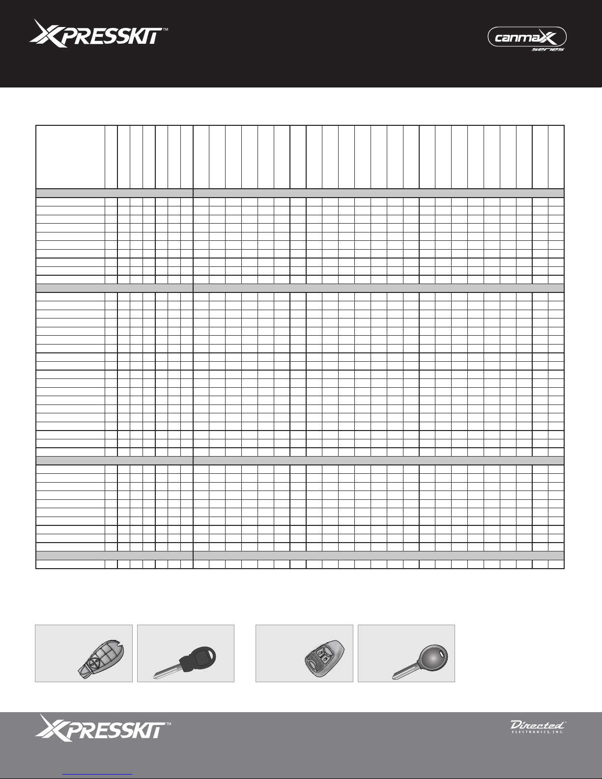
Vehicles
2010
2009
2008
2007
2006
2005
2004
DL-Arm Fac tory Security
DL-Disar m Factor y
Secur ity
DL-Door Loc k Control
DL-Door Unlock
DL-Sliding Door Control
Driver
DL-Sliding Door Control
Passenger
DL-Tr unk / Hatc h
Release
KI-Chry sler MUXX
Activation
KI-Key & Ignition.switch
Interface
PK-I mmobilize r Byp ass-
Data No Key Req'd
RS-Ignition Activation
RS-RAP Shut Down
(Remote ACC Power)
RS-Remote Start Ready
RS-Start (Crank)
Activation
RS-Tac h / RPM Output
SS-CAN Alarm control
w/ FOB r emote
SS-Entr y Monitor ing ALL
Door Pins
SS-Entr y Monitor ing
Driver Door Pin
SS-Entr y Monitor ing
Trunk /Hatch Pin
ST-Brak e Status (foot
brake)
ST-Hand Brak e Status
ST-Ignition Status
ST-Keys ense Status
Chrysle r
300/300c 1* 1* 1* •••• • ••• D••D DDDD
300/300c 3 3 3 •••• ••••••D••D•D•DDDD
Aspen 333 •••• ••••••D••D•D•DDDD
Pacifica 66666 •••• •• • D •D•D•D DD
PTCruiser 33333 •••• •••••D••D•D•DDDD
Sebring 3333 •••• ••••••D••D•D•DDDD
SebringConvertible333 •••• ••••••D••D•D•DDDD
Sebring Sedan 3333 •••• ••••••D••D•D•DDDD
Town & Country 1 1 1 ••••••• ••• D••D•D•DDDD
Town & Country 5555 ••••••• • D •D•D•D DD
Dodge
Avenger 3 3 3 •••• ••••••D••D•D•DDDD
Caliber 3333 •••• •••••D••D•D•DDDD
Caravan 111 ••••••• ••• D••D•D•DDDD
Caravan 5555 ••••••• • D •D•D•D DD
Challenger 1 1 1 •••• • ••• D••D•D•DDDD
Charger 1*1*1* •••• • ••• D••D DDDD
Charger 33 •••• ••••••D••D•D•DDDD
Dakota 3333 •••• •••••D••D•D DDDD
Dakota 44 •••• • • •D•D DDDD
Durango 3 3 3 •••• •••••D••D•D•DDDD
Durango 4 4 4 •••• • • •D•D•DDDD
GrandCaravan 111 ••••••• ••• D••D•D•DDDD
GrandCaravan 5555 ••••••• • D •D•D•D DD
Journey 11 •••• ••• D••D•D•DDDD
Magnum 1* •••• ••• D••D DDDD
Magnum 3 3 3 •••• •••••D••D•D•DDDD
Nitro 2222 •••• •••••D••D•D•DDDD
RAM 11 •••• ••• D••D•D DDDD
RAM 333 •••• •••••D••D•D DDDD
Jeep
Commander 1* 1* 1* •••• • ••• D••D DDDD
Commander 3 3 •••• ••••••D••D•D•DDDD
Compass 3333 •••• •••••D••D•D•DDDD
GrandCherokee 1*1*1* •••• ••• D••D DDDD
GrandCherokee 333 •••• •••••D••D•D•DDDD
Liberty 222 •••• •••••D••D•D•DDDD
Liberty 555 •••• • •D•D•D DD
Patriot 3333 •••• •••••D••D•D•DDDD
Wrangler 2222 •••• •••••D••D•D•DDDD
Wrangler Unlimited 2222 •••• •••••D••D•D•
DDDD
Volkswagen
Routan 11 ••••••• ••• D••D•D•DDDD
Legend:
D: Data-to- Data (D2D) only DL: OE Door Lock & Alarm Contr ols PK: Trans ponder & Immobilizer Override SS: Entry Point Status-Secur ity
•: D2Dand Wire- to-Wire (W2W) KI: Ignition Key Sw itch Interfac e RS: Engine Start & Status ST: Function/Feature Status
* In t hese vehicles, doors are not detected by t he dat a bus - use the door pins ins tead.
Firmware: CHRYSLER
Vehicle Application Guide
Vehicle Canbus Integration System
Rev.: 20110111
Page 2
Installation 1
WITH Keyless
Installation 1
WITHOUT Keyless
PANIC
Installation 2-3-4-5-6
WITH Keyless
PANIC
Installation 2-3-4-5-6
WITHOUT Keyless
CHRYSLER
The Mobile Integration Systems
© 2011 Directed Electronics. All rights reserved.
Page 3
Platform: XK09
Firmware: CHRYSLER
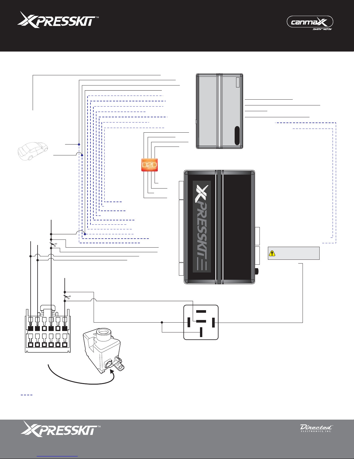
Installation Type 1
(-) Driver Door Pin
(-) Ground
(+) 12 V
(+) 12 V (Batt.)
(+) Ignition
CAN High
CAN Low
Rearm (RAP OFF)
(+) Ignition Output
(+) Starter Output
(-) Trunk Output
(-) Unlock Output
(-) Aux2 Right Sliding Door
(-) Aux1 Left Sliding Door
1: Blue/White: (-) GWR (status)
2: Violet/Black: (-) Aux2 Left Sliding Door
4: White/Violet: (-) Aux1 Right Sliding Door
3: Light Green: (-) Lock Input
5: Blue: (-) Unlock Input
6: Red/White: (-) Trunk Input
7: Violet: (+) Starter Input
8: Pink: (+) Ignition Input
9: Red: (+) 12 V
10: Black: (-) Ground
19: Tan: HSCAN Low
20: Tan/Black: HSCAN High
(-) Lock Output
(-) GWR (status)
1: (+) 12 V
2: RX
3: (-) Ground
4: TX
15: Yellow
17: Orange
(-) Ground
(+) 12 V
TX
(-) Ground
RX
(+) 12 V
4
20
2
Vehicle Canbus Integration System
Starter
Remote
(-) Neutral Safety (DEI platforms only)
(AC) Tach Input*
(-) Door/Trunk Sense Input
XK09
4: 3: -
4
2: Green: (-) Door/Trunk Sense Output
1: Violet/White: (AC) Tach Output*
4: -
The Relay wire must be
3: -
4
connected to the first pin on
the left of the connector.
2: 1: Red/Blue: Relay**
Programming Button
Rev.: 20110111
Page 3
(-) Door Status (1* only)
(-) Hood
Parking Lights
6
12
1
7
Facing view
Behind Ignition Switch
Not required in D2D mode.
* The Tach wire is an optional connection required on some remote starters not supporting tach signal in D2D.
** If the kit you have purchased does not include a 4-pin black harness to accommodate the Relay wire, use a D2D or relay pack harness.
The Mobile Integration Systems
Ignition
Barrel
86
87
87a
85
30
© 2011 Directed Electronics. All rights reserved.
Page 4
Platform: XK09
Firmware: CHRYSLER
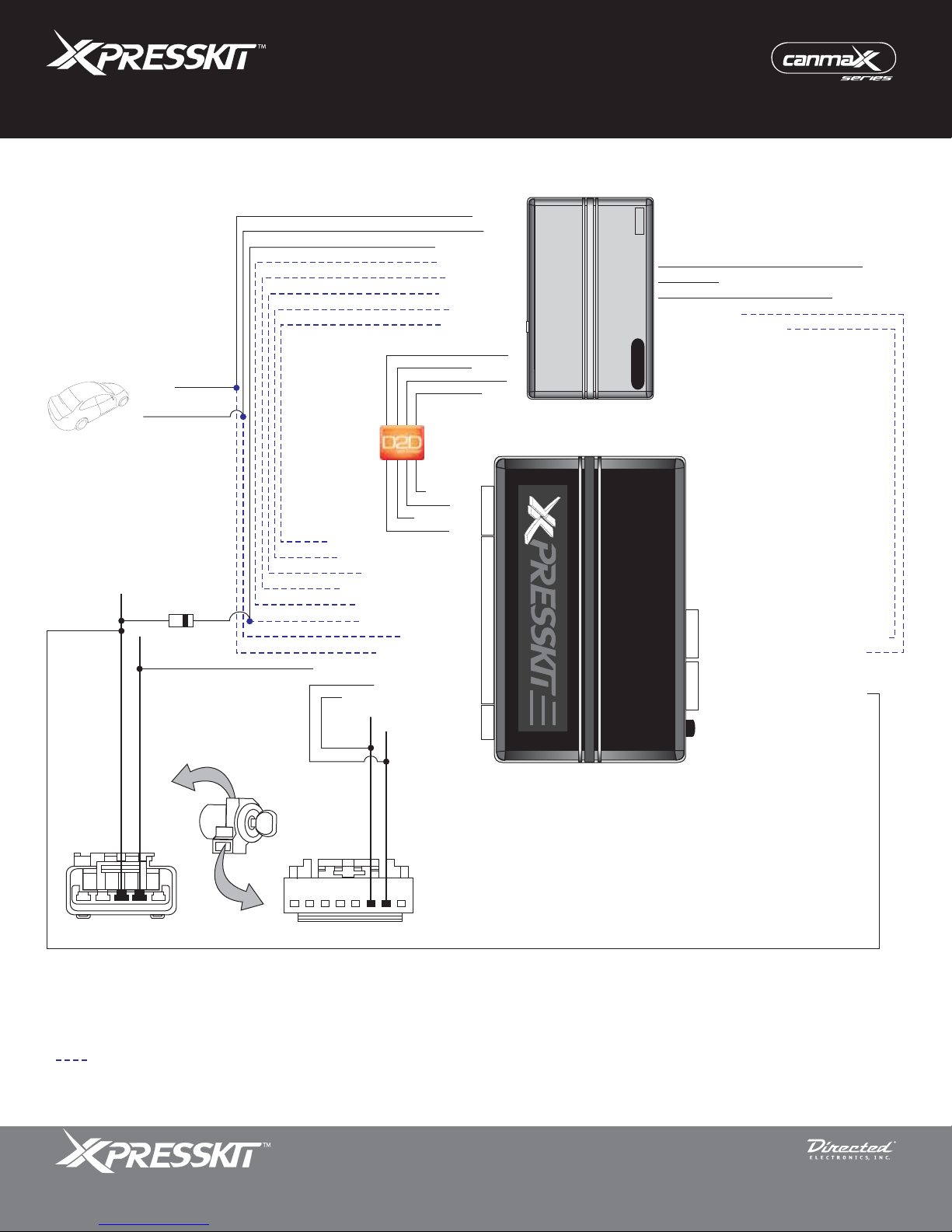
Installation Type 2
(-) Ground
(+) 12 V
(+) Ignition Output
(+) Starter Output
(-) Trunk Output
(-) Unlock Output
(-) Lock Output
(-) GWR (status)
1: (+) 12 V
2: RX
3: (-) Ground
1: Blue/White: (-) GWR (status)
3: Light Green: (-) Lock Input
5: Blue: (-) Unlock Input
6: Red/White: (-) Trunk Input
7: Violet: (+) Starter Input
8: Pink: (+) Ignition Input
9: Red: (+) 12 V
10: Black: (-) Ground
13: Violet/Brown: Multiplex Output
19: Tan: HSCAN Low
20: Tan/Black: HSCAN High
4: TX
(-) Ground
(+) 12 V
TX
(-) Ground
RX
(+) 12 V
4
20
2
Vehicle Canbus Integration System
Starter
Remote
(-) Neutral Safety (DEI platforms only)
(AC) Tach Input*
(-) Door/Trunk Sense Input
XK09
4: 3: -
4
2: Green: (-) Door/Trunk Sense Output
1: Violet/White: (AC) Tach Output*
4: 3: -
4
2: Pink/White: (+) Ignition Output**
1: -
Programming Button
Rev.: 20110111
Page 4
(-) Hood
Parking Lights
Violet/Brown, Pin 2
(+) Ignition, Pin 3
51
18
Facing view
CAN High, Pin 6
Facing view
CAN Low, Pin 7
Not required in D2D mode.
* The Tach wire is an optional connection required on some remote starters not supporting tach signal in D2D.
** If the kit you have purchased does not include a 4-pin black harness to accommodate the Ignition wire, use a D2D or relay pack harness.
The Mobile Integration Systems
© 2011 Directed Electronics. All rights reserved.
Page 5
Platform: XK09
Firmware: CHRYSLER
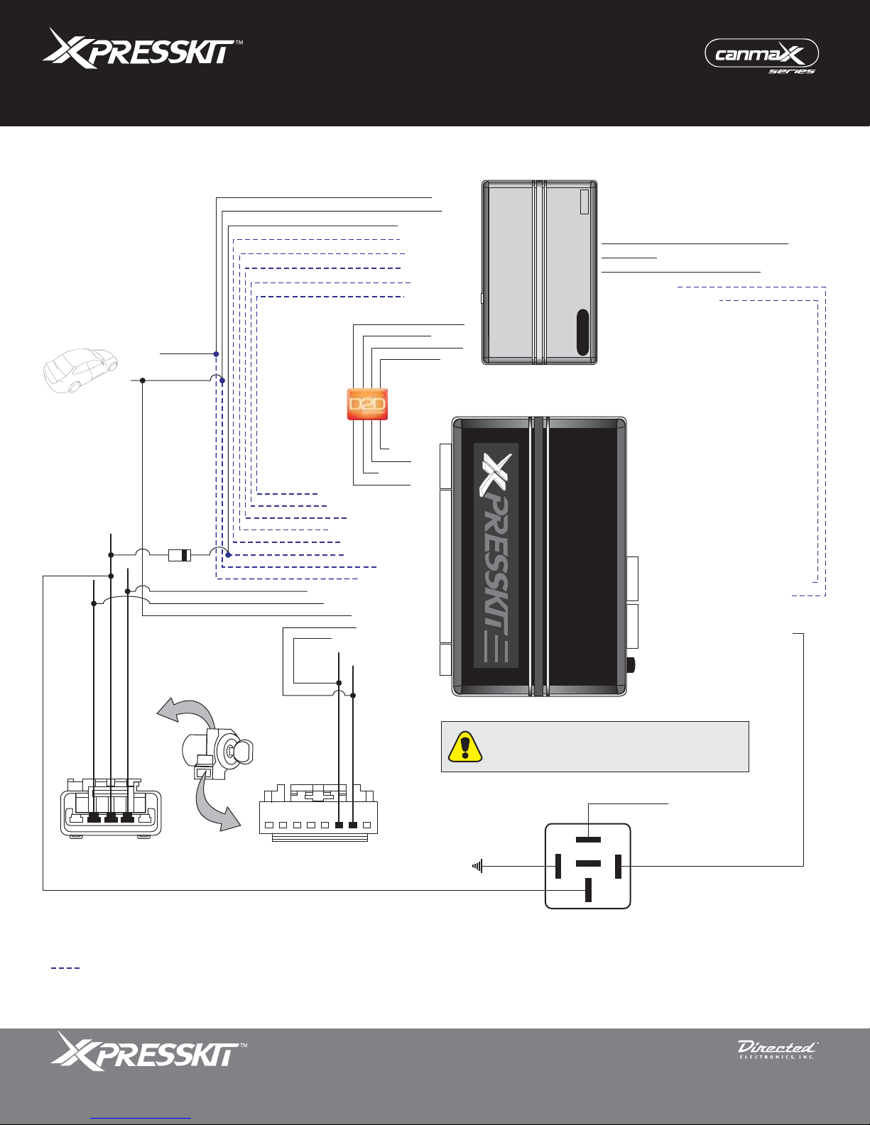
Installation Type 3
(-) Ground
(+) 12 V
(+) Ignition Output
(+) Starter Output
(-) Trunk Output
(-) Unlock Output
(-) Lock Output
(-) GWR (status)
1: (+) 12 V
2: RX
3: (-) Ground
1: Blue/White: (-) GWR (status)
3: Light Green: (-) Lock Input
5: Blue: (-) Unlock Input
6: Red/White: (-) Trunk Input
7: Violet: (+) Starter Input
8: Pink: (+) Ignition Input
13: Violet/Brown: Multiplex Output
10: Black: (-) Ground
15: Yellow: (+) Start Output***
16: Brown: (+) 12 V***
19: Tan: FTCAN Low
20: Tan/Black: FTCAN High
4: TX
9: Red: (+) 12 V
(-) Ground
(+) 12 V
TX
(-) Ground
RX
(+) 12 V
4
20
2
Vehicle Canbus Integration System
Starter
Remote
(-) Neutral Safety (DEI platforms only)
(AC) Tach Input*
(-) Door/Trunk Sense Input
XK09
4: 3: -
4
2: Green: (-) Door/Trunk Sense Output
1: Violet/White: (AC) Tach Output*
4: 3: -
4
2: Pink/White: (+) Ignition Output**
1: -
Programming Button
Rev.: 20110111
Page 5
(-) Hood
Parking Lights
Violet/Brown, Pin 2
(+) Ignition, Pin 3
(+) Start, Pin 4
CAN High, Pin 6
CAN Low, Pin 7
*** Only connect the Brown and the Yellow wires
if a (+) Start wire is present at the ignition switch
connector, on pin 4.
(+) 12 V
51
Facing view
18
Facing view
(-) Ground
86
87
87a
85
30
Not required in D2D mode.
* The Tach wire is an optional connection required on some remote starters not supporting tach signal in D2D.
** If the kit you have purchased does not include a 4-pin black harness to accommodate the Ignition wire, use a D2D or relay pack harness.
The Mobile Integration Systems
© 2011 Directed Electronics. All rights reserved.
Page 6
Platform: XK09
Firmware: CHRYSLER
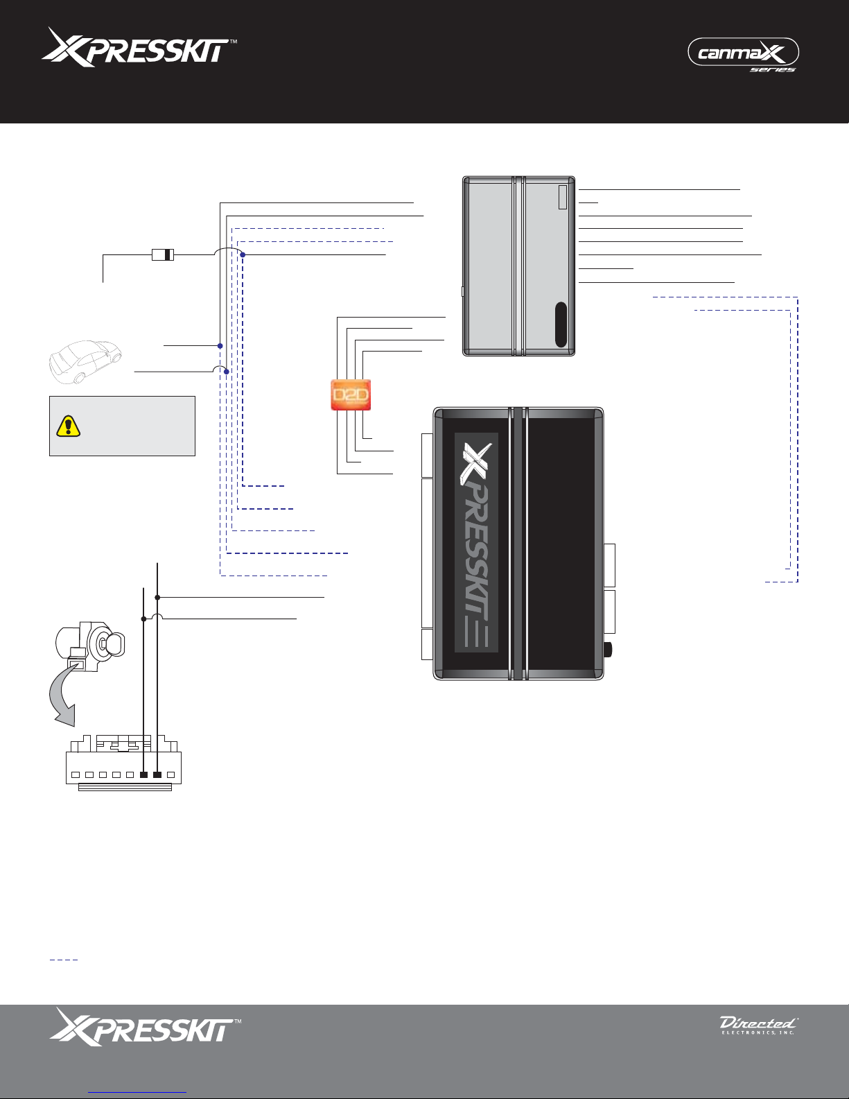
Installation Type 4
Vehicle Canbus Integration System
Rev.: 20110111
Page 6
(-) Key Sense
(-) Ground
(+) 12 V
Connect Key Sense
wire only if vehicle is
equipped with OEM
alarm.
CAN High, Pin 6
CAN Low, Pin 7
(-) Unlock Output
(-) Lock Output
(-) GWR (status)
1: (+) 12 V
2: RX
3: (-) Ground
1: Blue/White: (-) GWR (status)
3: Light Green: (-) Lock Input
5: Blue: (-) Unlock Input
9: Red: (+) 12 V
10: Black: (-) Ground
19: Tan: FTCAN Low
20: Tan/Black: FTCAN High
4: TX
(-) Ground
(+) 12 V
TX
(-) Ground
RX
(+) 12 V
4
20
2
Starter
Remote
(+) Accessory 1x (2x for Dodge Durango only)
(-) Neutral Safety (DEI platforms only)
(AC) Tach Input*
(-) Door/Trunk Sense Input
XK09
4: 3: -
2: Green: (-) Door/Trunk Sense Output
1: Violet/White: (AC) Tach Output*
Programming Button
(-) Accessory
(+) Starter
(+) Ignition 1
(+) Ignition 2
(-) Hood
Parking Lights
18
Facing view
Not required in D2D mode.
* The Tach wire is an optional connection required on some remote starters not supporting tach signal in D2D.
The Mobile Integration Systems
© 2011 Directed Electronics. All rights reserved.
Page 7
Platform: XK09
Firmware: CHRYSLER
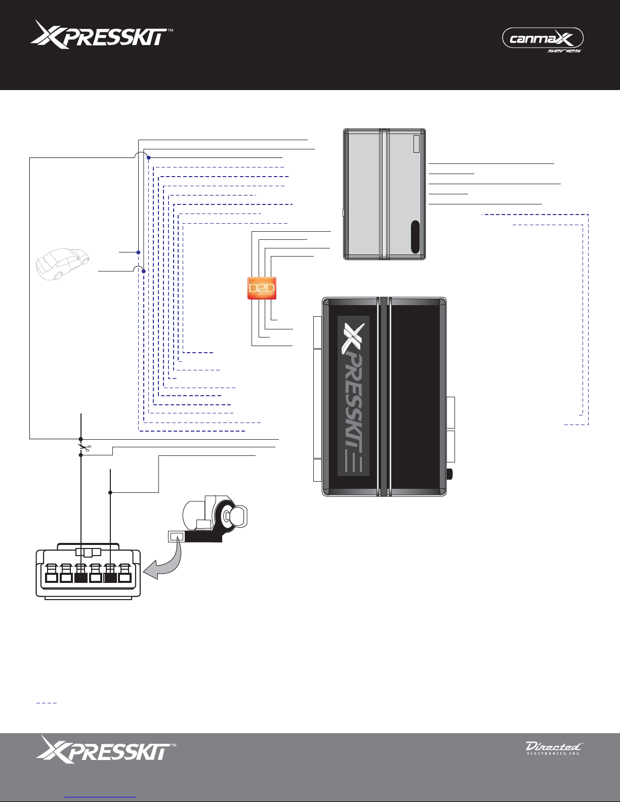
Installation Type 5
(-) Ground
(+) 12 V
Pin 4, Sentry Key
(+) Ignition
Pin 2, J1850
(+) Ignition Output
(+) Starter Output
(-) Trunk Output
(-) Unlock Output
(-) Aux2 Right Sliding Door
(-) Aux1 Left Sliding Door
1: Blue/White: (-) GWR (status)
2: Violet/Black: (-) Aux2 Left Sliding Door
3: Light Green: (-) Lock Input
4: White/Violet: (-) Aux1 Right Sliding Door
5: Blue: (-) Unlock Input
6: Red/White: (-) Trunk Input
7: Violet: (+) Starter Input
8: Pink: (+) Ignition Input
9: Red: (+) 12 V
10: Black: (-) Ground
18: Green: J1850
(-) Lock Output
(-) GWR (status)
1: (+) 12 V
2: RX
3: (-) Ground
4: TX
15: Yellow
17: Orange
(-) Ground
(+) 12 V
TX
(-) Ground
RX
(+) 12 V
4
20
2
Vehicle Canbus Integration System
Starter
Remote
(+) Accessory x2 (Jeep Liberty only)
(-) Neutral Safety (DEI platforms only)
(AC) Tach Input*
(-) Door/Trunk Sense Input
XK09
4: 3: -
4
2: Green: (-) Door/Trunk Sense Output
1: Violet/White: (AC) Tach Output*
4
Programming Button
Rev.: 20110111
Page 7
(+) Starter
(-) Hood
Parking Lights
16
Module-Sentry Key
Remote Entry
Not required in D2D mode.
* The Tach wire is an optional connection required on some remote starters not supporting tach signal in D2D.
The Mobile Integration Systems
© 2011 Directed Electronics. All rights reserved.
Page 8

Platform: XK09
Firmware: CHRYSLER
Installation Type 6
(-) Ground
(+) 12 V
Violet/Brown, Pin 2
51
Facing view
(+) Ignition Output
(+) Starter Output
(-) Trunk Output
(-) Unlock Output
(-) Lock Output
(-) GWR (status)
1: (+) 12 V
2: RX
3: (-) Ground
1: Blue/White: (-) GWR (status)
3: Light Green: (-) Lock Input
5: Blue: (-) Unlock Input
6: Red/White: (-) Trunk Input
7: Violet: (+) Starter Input
8: Pink: (+) Ignition Input
9: Red: (+) 12 V
10: Black: (-) Ground
13: Violet/Brown: Multiplex Output
18: Green: J1850
4: TX
15: Yellow
17: Orange
(-) Ground
(+) 12 V
TX
(-) Ground
RX
(+) 12 V
4
20
2
Vehicle Canbus Integration System
Starter
Remote
(-) Neutral Safety (DEI platforms only)
(AC) Tach Input*
(-) Door/Trunk Sense Input
XK09
4: 3: -
4
2: Green: (-) Door/Trunk Sense Output
1: Violet/White: (AC) Tach Output*
4
Programming Button
Rev.: 20110111
Page 8
(+) Starter
(-) Hood
Parking Lights
Pin 4, Sentry Key
(+) Ignition
Pin 2, J1850
16
Module-Sentry Key
Remote Entry
Not required in D2D mode.
* The Tach wire is an optional connection required on some remote starters not supporting tach signal in D2D.
The Mobile Integration Systems
© 2011 Directed Electronics. All rights reserved.
Page 9
Platform: XK09
Firmware: CHRYSLER
Vehicle Canbus Integration System
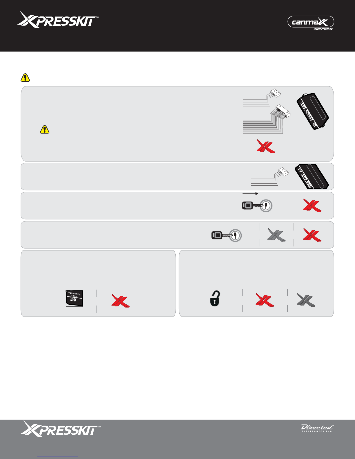
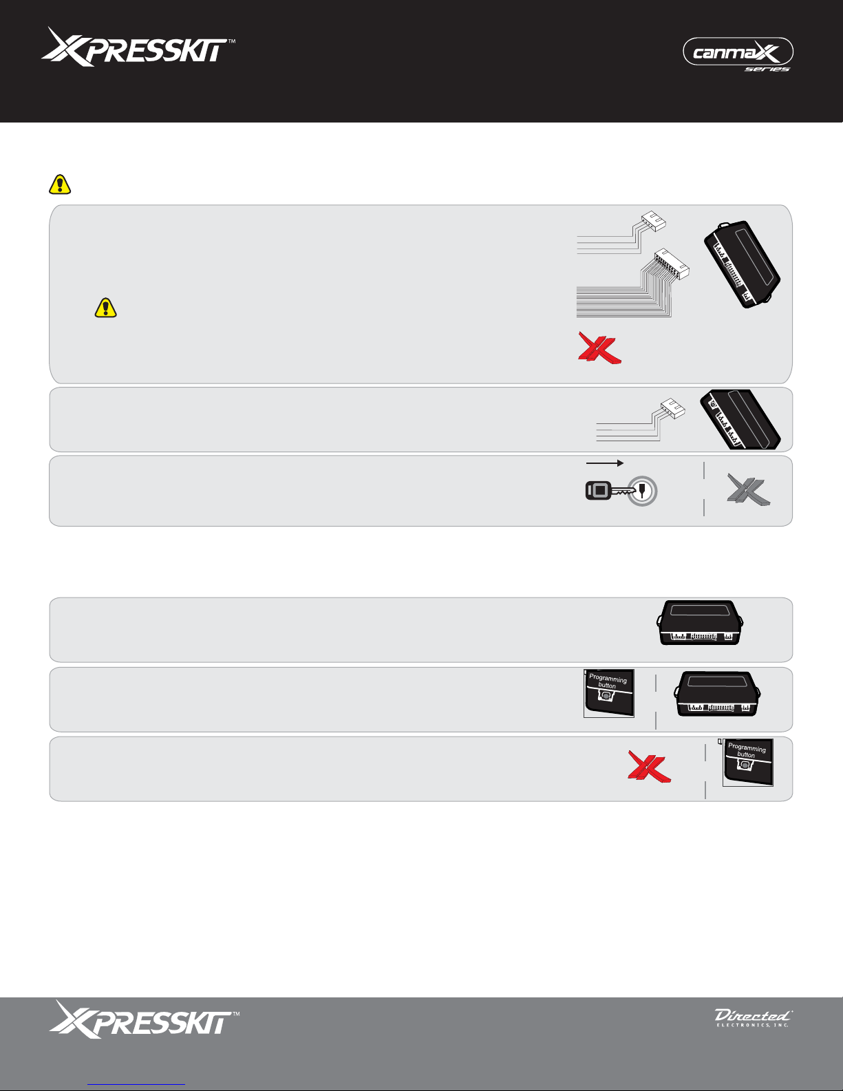
Module Programming for Types 1 to 4
Refer to the LED Diagnostics section on page 11 for more information and for troubleshooting purposes.
Rev.: 20110111
Page 9
If connected in D2D:
Connect the 4-pin D2D and the 20-pin harnesses.
If connected in W2W:
Connect the 20-pin harness.
1
2
3
Caution! The 20-pin connector can be easily plugged in backwards.
The LED turns ON solid or flashes rapidly.
Connect one or both of the other 4-pin harnesses, depending on the
requirements of each installation types.
Insert the key into the ignition barrel and turn it to ON. Wait for the LED
to start flashing slowly.
Turn the key back to the OFF position.
4
WITHOUT Factory Keyless Remote
Press the module Integrated Programming
Button (IPB). The LED turns ON solid for 3
seconds, then turns OFF. The module is now
5
programmed.
WITH Factory Keyless Remote
5
4-pin
20-pin
On Solid or Flashes
4-pin
KEY
KeyatON
KEY
KeyatOFF
Press the UNLOCK button on the factory keyless
remote. The LED turns ON solid for 3 seconds
and then turns OFF. The module is now
programmed and ready to operate.
OFF
ON
START
OFF
ON
START
Off
&
Flashes
&&
Flashes
&
FlashesPress
The Mobile Integration Systems
Press Unlock
& &
On 3 secs
© 2011 Directed Electronics. All rights reserved.
Off
Page 10
Platform: XK09
Firmware: CHRYSLER
Vehicle Canbus Integration System
Module Programming for Types 5 and 6
Refer to the LED Diagnostics section on page 11 for more information and for troubleshooting purposes.
Rev.: 20110111
Page 10
If connected in D2D:
Connect the 4-pin D2D and the 20-pin harnesses.
If connected in W2W:
Connect the 20-pin harness.
1
2
3
Caution! The 20-pin connector can be easily plugged in backwards.
The LED turns ON solid.
Connect one or both of the other 4-pin harnesses, depending on the
requirements of each installation types.
Insert the key into the ignition barrel and turn it to ON. Wait for the LED
to turn OFF (it could take up to 10 seconds). The module is now
programmed and ready to use.
Module Reset
4-pin
20-pin
On Solid
4-pin
KEY
KeyatON
OFF
ON
START
&
Off
Disconnect the module from any power source.
1
Press and HOLD the Integrated Programming Button (IPB).
While holding the button, connect the module to the power source.
2
Wait until the red LED flashes once and release the Integrated Programming
Button (IPB).
3
Disconnect from Power
Press & Hold
Flashes Once
&
Connect to Power
&
Release
The Mobile Integration Systems
© 2011 Directed Electronics. All rights reserved.
Page 11
Platform: XK09
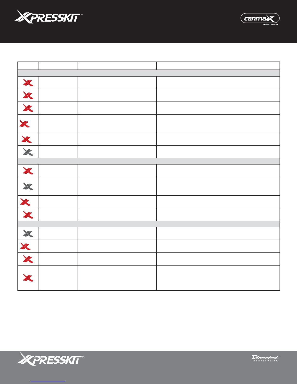
LED Status
Description
Troubleshooting
Module Programming
Solid The bus type cannot be detected.
Make sure the connections to the data bus are correct
and insert the key in the ignition switch.
Flashing
quickly
The vehicle type cannot be
detected.
Insert the key in the ignition switch and turn to the ON
position. You may need to wait up to 10 seconds.
Flashes slowly Waiting for keyless.
Remove the key from the ignition switch and press a
keyless button, or the Programming button.
Solid for 3
seconds
Module was successfully
programmed or is already
programmed.
Normal operation.
Flashes once
quickly
Modules was reset. Normal operation.
Off Module has no power. Check the power connections.
Active Ground While Running
Solid Incorrect behavior.
Data is not processing correctly . Disconnect the power
from the module and power up.
Off Ground while running (status ) off.
Make sure the module was programmed, i.e. the D2D
harness is properly connected or thegroundwhile
running (status) wire is connected (if in W 2W mode).
Flashes for 1
second
A command is processing. Normal operation.
Flashes Ground while running (status) on. Normal operation.
Inactive Ground While Running
Off Ground while running (status) is off. Normal operation.
Flashes for 1
second
A command is processing. Normal operation.
Solid Incorrect behavior.
Data is not processing correctly . Disconnect the power
from the module and power up.
Flashes Ground while running (status) on.
Module did not receive ground while running (status) off.
Make sure the D2D harness is properly connected or
the ground while running (status) wire is not shorted to
ground.
Firmware: CHRYSLER
LED Diagnositics and Troubleshooting
x3
secs
x1
Vehicle Canbus Integration System
Rev.: 20110111
Page 11
x1
sec
x1
sec
The Mobile Integration Systems
© 2011 Directed Electronics. All rights reserved.
Page 12

Platform: XK09
Firmware: CHRYSLER
Vehicle Canbus Integration System
Rev.: 20110111
Page 12
Limited One-Year Consumer Warranty
For a period of ONE YEAR from the date of purchase of a Directed Electronics remote start or security product, Directed
Electronics. (“DIRECTED”) promises to the original purchaser, to repair or replace with a comparable reconditioned piece, the
security or remote start accessory piece (hereinafter the “Part”), which proves to be defective in workmanship or material
under normal use, provided the following conditions are met: the Part was purchased from an authorized DIRECTED dealer;
and the Part is returned to DIRECTED, postage prepaid, along with a clear, legible copy of the receipt or bill of sale bearing the
following information: consumer’s name, address, telephone number, the authorized licensed dealer’s name and complete
product and Part description.
This warranty is nontransferable and is automatically void if the Part has been modified or used in a manner contrary to its
intended purpose or the Part has been damaged by accident, unreasonable use, neglect, improper service, installation or
other causes not arising out of defect in materials or construction.
TO THE MAXIMUM EXTENT ALLOWED BY LAW, ALL WARRANTIES, INCLUDING BUT NOT LIMITED TO EXPRESS
WARRANTY, IMPLIED WARRANTY, WARRANTY OF MERCHANTABILITY, FITNESS FOR PARTICULAR PURPOSE AND
WARRANTY OF NON INFRINGEMENT OF INTELLECTUAL PROPERTY, ARE EXPRESSLY EXCLUDED;AND DIRECTED
NEITHER ASSUMES NOR AUTHORIZES ANY PERSON OR ENTITY TO ASSUME FOR IT ANY DUTY, OBLIGATION OR
LIABILITY IN CONNECTION WITH ITS PRODUCTS. DIRECTED HEREBY DISCLAIMS AND HAS ABSOLUTELY NO
LIABILITY FOR ANY AND ALL ACTS OF THIRD PARTIES INCLUDING DEALERS OR INSTALLERS. IN THE EVENT OF A
CLAIM OR A DISPUTE INVOLVING DIRECTED OR ITS SUBSIDIARY, THE PROPER VENUE SHALL BE SAN DIEGO
COUNTY IN THE STATE OF CALIFORNIA. CALIFORNIA STATE LAWS AND APPLICABLE FEDERAL LAWS SHALLAPPLY
AND GOVERN THE DISPUTE. THE MAXIMUM RECOVERY UNDER ANY CLAIM AGAINST DIRECTED SHALL BE
STRICTLY LIMITED TO THE AUTHORIZED DIRECTED DEALER’S PURCHASE PRICE OF THE PART. DIRECTED SHALL
NOT BE RESPONSIBLE FOR ANY DAMAGES WHATSOEVER, INCLUDING BUT NOT LIMITED TO, ANY
CONSEQUENTIAL DAMAGES, INCIDENTAL DAMAGES, DAMAGES FOR THE LOSS OF TIME, LOSS OF EARNINGS,
COMMERCIAL LOSS, LOSS OF ECONOMIC OPPORTUNITY AND THE LIKE. NOTWITHSTANDING THE ABOVE, THE
MANUFACTURER DOES OFFERA LIMITED WARRANTY TO REPLACE OR REPAIR AT DIRECTED’S OPTION THE PART
AS DESCRIBEDABOVE.
Some states do not allow limitations on how long an implied warranty will last or the exclusion or limitation of incidental or
consequential damages. This warranty gives you specific legal rights and you may also have other rights that vary from
State to State. DIRECTED does not and has not authorized any person or entity to create for it any other obligation,
promise, duty or obligation in connection with this Part.920-0007 07-06
This Interface kit / Data Bus Interface part has been tested on the listed vehicles. Other vehicles will be added to the select
vehicle list upon completion of compatibility testing. Visit website for latest vehicle application guide. : Under no
DISCLAIMER
circumstances shall the manufacturer or the distributors of the bypass kit / data bus interface part(s) be held liable for any
consequential damages sustained in connection with the part(s) installation. The manufacturer and it’s distributorswill not, nor
will they authorize any representative or any other individual to assume obligation or liability in relation to the interface kit / data
bus interface part(s) other than its replacement.
N.B.:Under no circumstances shall the manufacturer and distributors of this
product be liable for consequential damages sustained in connection with this product and neither assumes nor authorizes
any representative or other person to assume for it any obligation or liability other than the replacement of this product only.
PROTECTED BY U.S. PATENTS:
B2; 6,696,927 B2; 6,756,885 B1; 6,756,886 B2; 6,771,167 B1; 6,812,829B1; 6,924,750 B1; 7,010,402 B1; 7,015,830 B1; 7,031,826 B1; 7, 046,126 B1;
7,061,137 B1; 7,068,153 B1; 7,205,679 B1; 2,320,248; 2,414,991; 2,415,011; 2,415,023;2,415,027; 2,415,038; 2,415,041; 2 , 420,947;
2,426,670; 2,454,089 1,053,128
5,719,551; 6,011,460 B1 *;6,243,004 B1; 6,249,216 B1; 6,275,147B1; 6,297,731 B1; 6,346,876 B1; 6,392,534 B1; 6,529,124
DN.PATENT:
E
UROPEAN PATENT:PAT.PENDING: MADE IN CANADA2,291,306;
C
The Mobile Integration Systems
© 2011 Directed Electronics. All rights reserved.
 Loading...