

Page 1
INSTALLATION GUIDE
MODEL: PKUCG2X
CHRYSLER 2ND GEN AND GM PASSKEY 3+
TYPE RF TRANSPONDER BYPASS
PRODUCT FEATURES
GM:
Cover all new GM equipped with the GM PASS- Key III Plus
Chrysler:
Built in MUX Wire (2nd start & 2nd accessory) activation output to streamline installation
Activates Chrysler starter low circuit (MUX) required on most late model Chrysler & Dodge vehicles
- Compatible with any remote car starter
- Compatible with manufacturer’s anti-theft & content theft security system
- Maintains integrity of manufacturer’s anti-theft immobilizer system
- No extra key required for operation
- Easy programming
PRODUCT DESCRIPTION
GM PASS- Key III Plus, bypass for vehicles equipped with the new style hybrid Passlock (resistance) and Passkey
3+ (transponder) type anti-theft system.
Chrysler transponder bypass kit for all 2nd generation encrypted Sentry key immobilizer. The PKUCG2X also
features an extra output designed to activate the Chrysler MUX circuit. Compatible with the CHWFR for 2008+
Chrysler vehicles equipped with laser style key.
transponder
PK
BYPASS
† Buick, Cadillac, Chrysler, Chevrolet, Jeep, Suzuki, Saturn, Mitsubishi, Dodge, GM, Pontiac and Hummer are registered trademarks and property of their respective companies.
MODEL: pkucg2x
Rev.: 20091028
© 2008 Directed Electronics. All rights reserved.
Page 2
MODEL: pkucg2x
Rev.: 20091028
© 2008 Directed Electronics. All rights reserved.
Page 3
2008 2007 2006 2005 2004 2003
Enclave
D
D D D
D
Lucerne
CTS
DTS
D
D
D
D
D
D D
D
D
D
D
D
Escalade
SRX
Avalanche
Cobalt
Equinox
D
ExpressVan
D
HHR
D D D
Impala
D D D
Malibu
D D D D
MalibuMAXX
D D D D
MonteCarlo
D D
Silverado
D D
Suburban
D D
Tahoe
D D
300/300c
C A / B
A / B
A / B
A / B
A / B
A / B
A / B
A / B
A / B
A
A
A / B
A / B
A / B
A / B
A / B
A / B
A / B
A / B
A / B
A / B
A / B
A / B
A / B
A / B
A / B
A / B
A / B
A / B
A / B
A / B
A / B
A / B
A / B
A / B
A / B
A / B
A / B
A / B
A / B
A / B
A / B
A / B
A / B
A / B
A / B
A / B
A / B
A / B
A / B
A / B
B
B
B
A
A
A / B
A / B
A / B
A / B
B
B
B
B
A
A
A
A / B
A / B
A / B
A / B
Aspen
Pacifica
PTCruiser
SebringConvertible
SebringSedan
Town&Country
C
Avenger
Caliber
Caravan
C
Charger
C
Dakota
Durango
GrandCaravan
C
Magnum
C
Nitro
RAM
2008 2007 2006
Acadia
D D
Savana
D
Sierra
D D
Yukon
DDD
H2
Commander
Compass
GrandCherokee
C
GrandCherokeeLimited
C
Liberty
Patriot
Wrangler
WranglerUnlimited
Raider
G5
D D
G6
D D
Pursuit
D D
Solstice
D D
Torrent
D D
Aura
D D
Outlook
D D
Sky
D D
VUE
D
XL7
D D
A / B A / B
A / B
A / B
A / B
2005
D
D
D
D
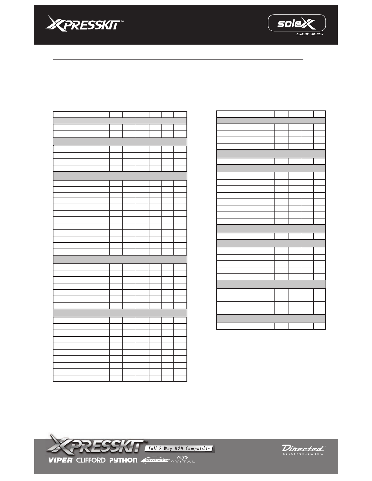
Because the
vehicles, note that there are 4 different wiring diagrams. The
chart below will tell you by vehicle which wiring diagram to use.
PKUCG2X is compatible with a large number of
VEHICLE COMPATIBILITY CHART AND INSTALLATION TYPE
Page 1 to 8
Buick
Cadillac
Chevrolet
Chrysler
Dodge
Suzuki
Saturn
Pontiac
Mitsubishi
Jeep
Hummer
GMC
MODEL: pkucg2x
Rev.: 20091028
© 2008 Directed Electronics. All rights reserved.
Page 4
Red
Green
Blue
Violet
Black
Violet/White
Pink
Pink/White
Brown
Orange
10
P
I
N
HARNE
SS
(-) To Ground When
Running Output (status)
Ground
Batt + 12v
Input
Input
Input
N/CN/C
N/C
N/C
N/C
N/CN/C
N/C
N/CN/C
or Alarm System
Remote Control
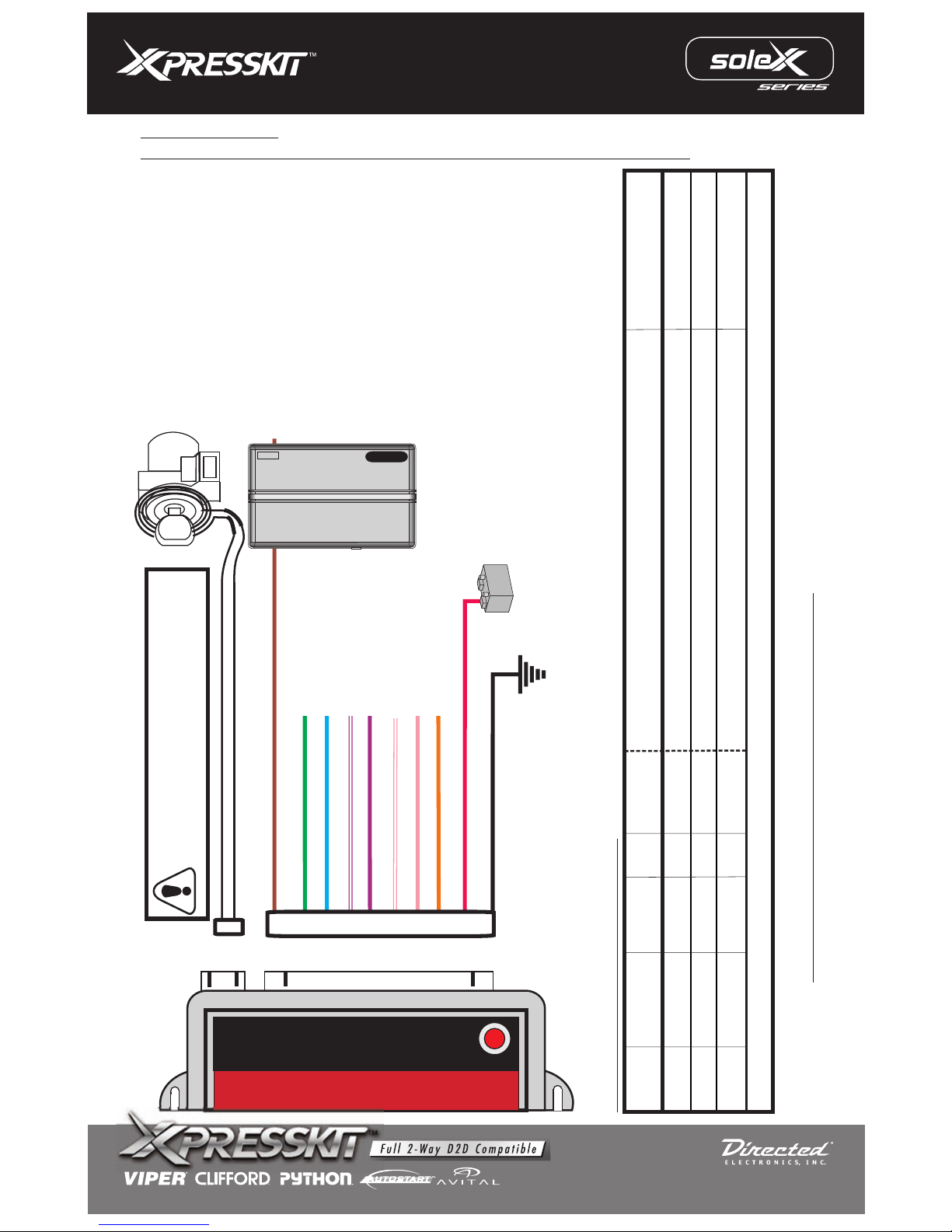
WIRE GUIDE: CONNECTIONS
To program the module, see page 7
Section B
Section C
INSTALL “A”:
CHRYSLER 2ND GENERATION TRANSPONDER without OEM ALARM ONLY
Section A
- 3 or 5 turns of loop are required.
- You can program the transponder only once.
- Do not install on metal surface.
10 PIN HARNESS
(-)
/(+)
I/O
STATUS
WIRE
COLOR
SPECIFIC WIRE CONNECTION LOCATION
Connect
Location
Constant (+) 12 Volt Source
Chassis Ground
Legend: RCS = Remote Control System N/C = No Connection N/A = Not Applicable
Brown
RCS
Red
Input
Input
(+)
Vehicle
Black
Input
(-)
Vehicle
PIN #
1
9
10
(-)
FUNCTIONS
Ground out when running (status) from remote starter
Turn ON module
Power Source
Ground Source
+12VDC
Page 2 to 8
MODEL: pkucg2x
Rev.: 20091028
© 2008 Directed Electronics. All rights reserved.
Page 5
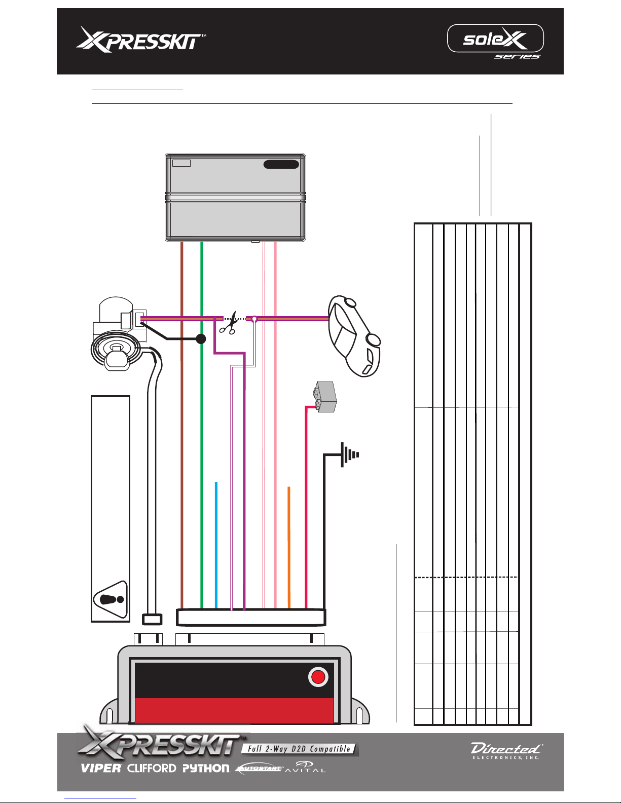
Red
Blue
Black
Brown
Orange
10 P
I
N
HARNE
SS
(-) To Ground When
Running Output (status)
Ground
Batt + 12v
Input
Input
Input
N/C
N/C
or Alarm System
Remote Control
WIRE GUIDE: CONNECTIONS
Section B
Section C
Section A
- 3 or 5 turns of loop are required.
- You can program the transponder only once.
- Do not install on metal surface.
10 PIN HARNESS
Cut Wire
Violet/Brown
*Some vehicle do not
have Starter wire
Green
(+) Starter
Input
Violet
Violet/White
Pink
Pink/White
MUX to Violet/Brown BCM side
MUX to Violet/Brown KEY side
Ignition in +
Disarm in -
N/A
N/A
Input
Input
(-)
/(+)
I/O
STATUS
WIRE
COLOR
SPECIFIC WIRE CONNECTION LOCATION
Connect
Location
Constant (+) 12 Volt Source
Chassis Ground
Legend: RCS = Remote Control System N/C = No Connection N/A = Not Applicable
Green
Brown
RCS
Violet/White
Violet
Red Input
Input
(+)
Vehicle
Black Input
(-)
Vehicle
Pink/White
Pink
PIN
1
2
4
5
6
7
9
10
(-)
FUNCTIONS
Ground out when running (status) from remote starter
Turn ON module
Power Source
Ground Source
Starter Output from remote starter (RCS)
Connect to MUX wire, on BCM side (Violet/Brown) Starter/2nd Start & Accessory (Resistance) Activation
Starter/2nd Start & Accessory (Resistance) ActivationConnect to MUX wire, on KEY side (Violet/Brown)
Disarm Output remote starter (RCS)
Ignition Output remote starter (RCS)
N/A N/A
N/AN/A
Vehicle
Vehicle
Disarm Factory Alarm
RCS
Input
(-)
Activate Ignition
Input
(+) RCS
Second Start Activation
Input
(+)
Vehicle
INSTALL “B”:
CHRYSLER 2ND GENERATION TRANSPONDER with OEM ALARM and Multiplex ignition
+1
2VDC
Page 3 to 8
To program the
module, see page 7
MODEL: pkucg2x
Rev.: 20091028
© 2008 Directed Electronics. All rights reserved.
Page 6
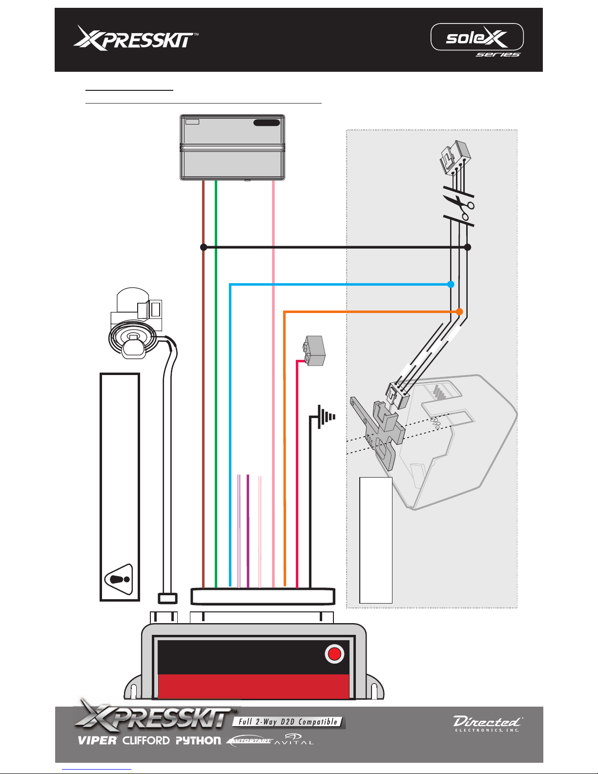
INSTALL “C”:
FOR CHRYSLER & DODGE & JEEP 2008 VEHICLES
1
0 PIN HARNESS
Section A
- 3 or 5 turns of loop are required.
- You can program the transponder only once.
- Do not install on metal surface.
Red
Green
Blue
Violet
Black
Violet/White
Pink
Pink/White
Brown
Orange
Ground
Batt 12v +
Input
Input
Input
Input
Output
Output
Input
Starter in +
Ignition Out +
Ignition
Accessory
N/C
N/C
N/C
(+)
(-)
(-)
N/C
N/C
N/C
(+)
(+)
(+)
(+)
(-) To Ground When Running Output (status)
+1
2VDC
or Alarm System
Remote Control
White
Blue
Black
Red
See next page for installing
instruction of the Key Interface
module into key barrel.
Page 4 to 8
*CHWFR is
not included
MODEL: pkucg2x
Rev.: 20091028
© 2008 Directed Electronics. All rights reserved.
Page 7
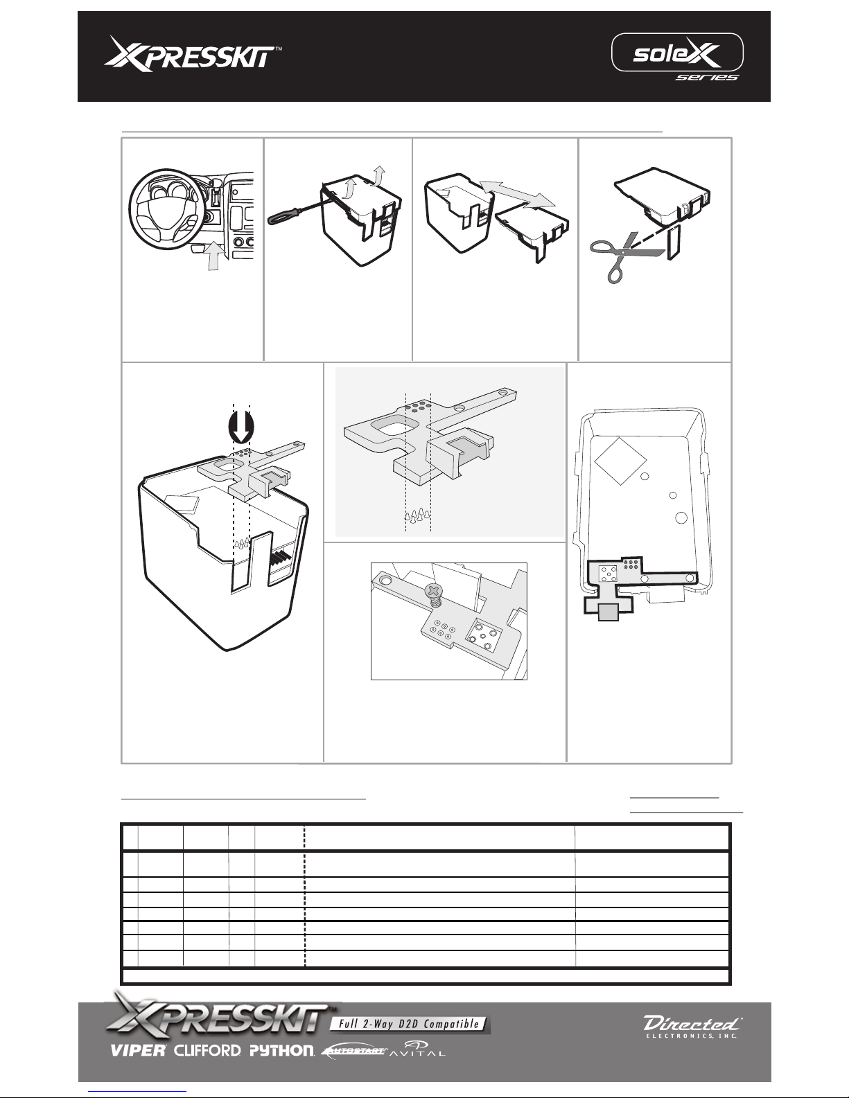
STEP 5
STEP 4
STEP 1
STEP 2
Remove the wireless
ignition node from the
dashboard. (Disassemble
the dash to access the
ignition barrel)
STEP 8
STEP 6
STEP 7
Slide open the cover of the
wireless ignition node.
Cut the lip off the cover.
Insert the CHWFR circuit
board as shown.
Ensure the
board is well aligned.
CHWFR circuit
Align the
circuit board with the
6 pins on the wireless
ignition node.
CHWFR
Using supplied screw ONLY, apply LOCTITE to
screw and secure* wafer into PCB as per
diagram. Reassemble key module and install
back into the vehicle.
* Be sure not to over tighten the screw as
damage to the factory circuit board may occur.
Use a flat screw driver
to lift out the 2 tabs on
each side of the cover.
STEP 3
Install key interface into wireless ignition node
(-)
/(+)
I/O
STATUS
WIRE
COLOR
SPECIFIC WIRE CONNECTION LOCATION
Connect
Location
Constant (+) 12 Volt Source
Chassis Ground
Legend: RCS = Remote Control System N/C = No Connection N/A = Not Applicable
Blue
Green
Brown
RCS
Orange
Red
Input
Input
(+)
Vehicle
Black
Input
(-)
Vehicle
Pink
PIN#
1
2
3
7
8
9
10
(-)
FUNCTIONS
Power Source
Ground Source
Connect to (-) When Running (status), output of RCS
Activate the module
.Remote Starter Interface
Input
(+)
RCS
Connect to Starter wire at Remote Starter or CHWFR
Starter input +
Vehicle
Output
(+)
Connect to PIN 1 at ignition barrel (See FIG.: 2)
Ignition output
RCS
Input
(+)
Connect to ignition wire at Remote Starter or CHWFR
Ignition input
Vehicle
Output
(+)
Connect to PIN 2 at ignition barrel (See FIG.: 2)
Accessory output
WIRE GUIDE: CONNECTIONS
Section B
10 PIN HARNESS
Page 5 to 8
Section C
To program the
module, see page 7
MODEL: pkucg2x
Rev.: 20091028
© 2008 Directed Electronics. All rights reserved.
Page 8
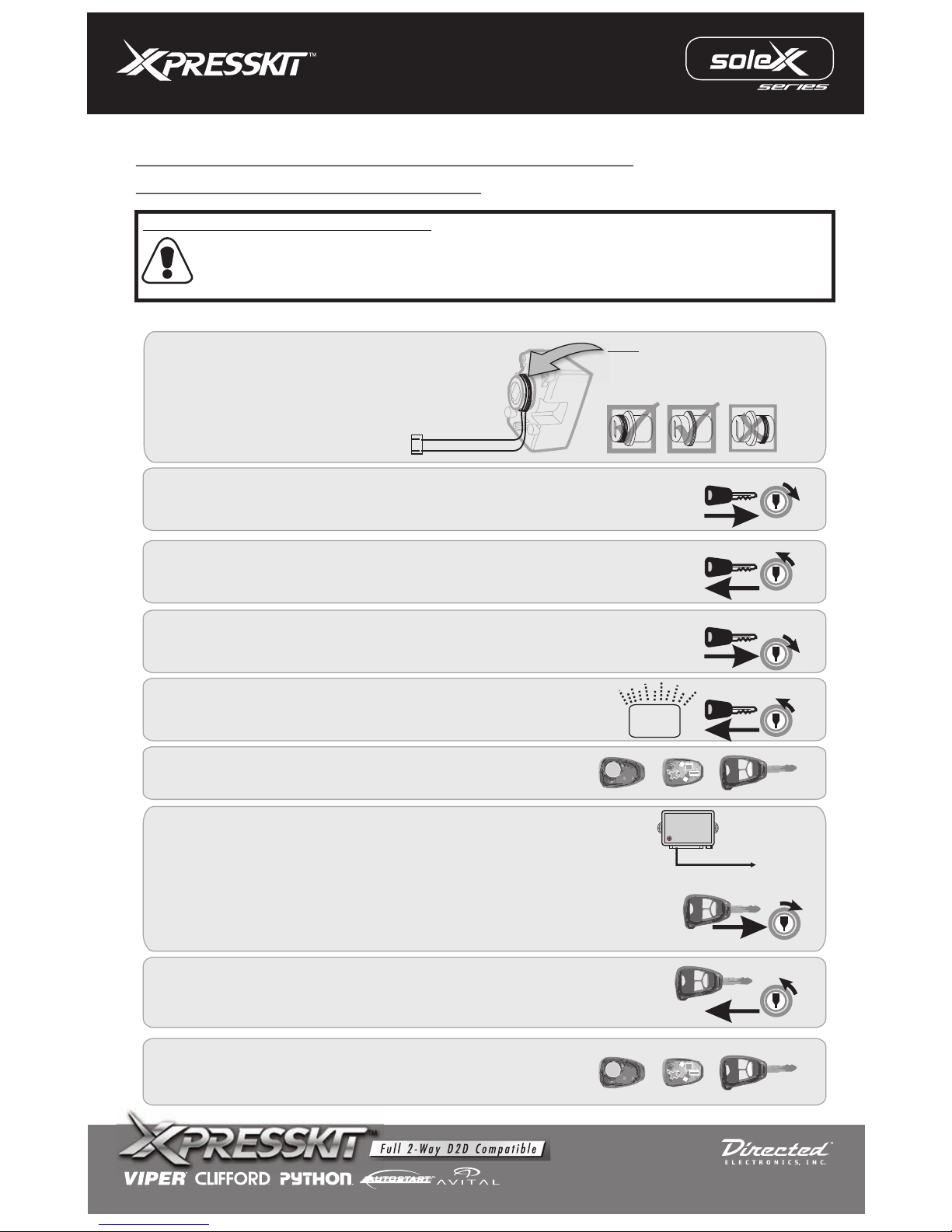
IGN
ON
OFF
Turn the key off and remove the key.
Remove the brown wire from ground and connect to (-) ground when running (status)
output from remote starter.
Section C
The PKUCG2X is compatible with 2004 Dodge Durango. However, all Durango’s built prior to 5 / 17 / 2004 must get a
WCM module upgrade wich will correct a problem preventing the vehicle from learning additional keys. Chrysler is
correcting this issue only when a Durango owner requests a new transponder key. The PKUCG2X must be programmed
as would an additional key. The WCM replacement part number is 56038675AS.
A) P ound the vehicle's
ignition cylinder as shown.
B) Plug the 2 pin loop antenna ring connector into the
2 pin connector of the module.
lace the loop antenna ring ar
Note
Move antenna loop as close to
the front of the ignition cylinder
(factory receiver ring) as possible.
IGN
IGN
IGN
IGN
IGN
ON
ON
ON
ON
ON
OFF
OFF
OFF
OFFOFF
KEY#1
KEY#1
KEY#2
KEY#2
Insert the first valid key into the ignition switch and turn it ON for at least 5
seconds, but no longer than 15 seconds.
Turn the ignition switch OFF and remove the first key.
Within 5 seconds insert the second valid key and turn the ignition switch ON.
After 10 seconds a chime will sound and the security light will begin to flash.
Turn the ignition switch OFF and remove the second key.
Security
2
3
4
5
6
7
8
1
Remove cover and PC board from factory remote
*Remove the screw immediatly on the back of factory remote as shown on illustration at step 6
Within 20 seconds from step 5, jump the brown wire (ground when running
output (-) status) of the PKUCG2X to ground.
Programming is now completed. You can close the
remote and re-install the screw.
To ground
Brown
9
For Durango 2004 built before 17/05/04
PROGRAMMING MODE FOR CODED CHRYSLER
KEY with INTEGRATED REMOTE
*You will need 2 valid keys
Page 6 to 8
Then, insert key (with the PC board removed) to the ignition position for a
period of 10 sec, you will hear a chime, the light will turn on for 3 sec. Keep the
key at this position for 5 sec.
MODEL: pkucg2x
Rev.: 20091028
© 2008 Directed Electronics. All rights reserved.
Page 9
87
87A
30
86
85
Relay
Red
Green
Blue
Violet
Black
Violet/White
Pink
Pink/White
Brown
Orange
10 PIN HARNESS
(-) To Ground When Running Output (status)
Ground
Batt + 12v
Input
Input
Input
N/CN/C
N/C
N/C
N/C
N/CN/C
N/C
N/C
N/C
N/C
N/C
N/C
N/C
Ignition (See next page for wire color)
+12v Constant
Accessory (See next page for wire color)
5V Reference (See next page for wire color)
+12v
constant
fused
Cut
RCS
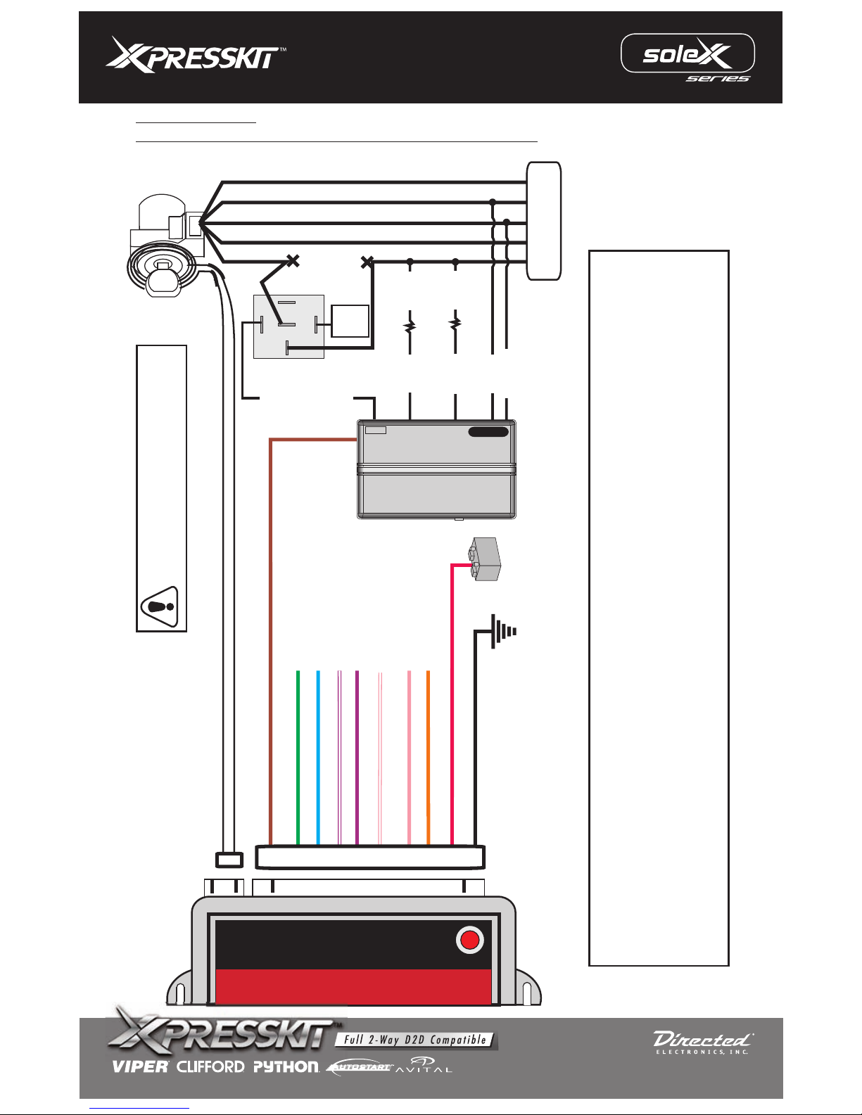
INSTALL “D”
GM VEHICLES EQUIPPED WITH THE GM PASS-KEY III PLUS
Section A
- 3 or 5 turns of loop are required.
- You can program the transponder only once.
- Do not install on metal surface.
9.6K
Resistor
2nd acc.
Accessory
Ignition
+Starter
Ground out (-) status
6.3K
Resistor
BCM
+1
2VDC
The Resistor code wire shows 12V for key sense, 5V during accessory and ignition, and just under 4V during
crank. This is due to the ignition switch shorting a 1300 ohm resistor between the Resistor code & the 5v
Reference wires. This diagram keeps the vehicle from setting off codes. Although these codes do not bring up
any lights on the dash they are still stored into the computer of the vehicle. If a dealer hooks up a scan tool they
will see this and will be able to blame it on the remote start. For troubleshooting a vehicle that uses this diagram
that will not remote start the vehicle would only require bypass, ignition & accessory, and tach to crank the
vehicle and start. Make sure you have the ignition, and test the tach source. Do not try to remote start without
wiring this diagram or those codes will be stored into the vehicles computer.
Page 7 to 8
MODEL: pkucg2x
Rev.: 20091028
© 2008 Directed Electronics. All rights reserved.
Page 10
(-)
/(+)
I/O
STATUS
WIRE
COLOR
SPECIFIC WIRE CONNECTION LOCATION
Connect
Location
WIRE GUIDE: CONNECTIONS 10 PIN HARNESS
Constant (+) 12 Volt Source
Chassis Ground
Legend: RCS = Remote Control System N/C = No Connection N/A = Not Applicable
Brown
RCS
Red Input
Input
(+)
Vehicle
Black Input
(-)
Vehicle
PIN#
1
9
10
Section B
(-)
FUNCTIONS
Ground out when running (status) from remote starter
Turn ON module
Power Source
Ground Source
1- Insert key and turn to “ON” position.
2- Turn “OFF” and remove.
3- Within 10 seconds, remote start the vehicle.
Module is now programmed.
TRANSPONDER PROGRAMMING
Section C
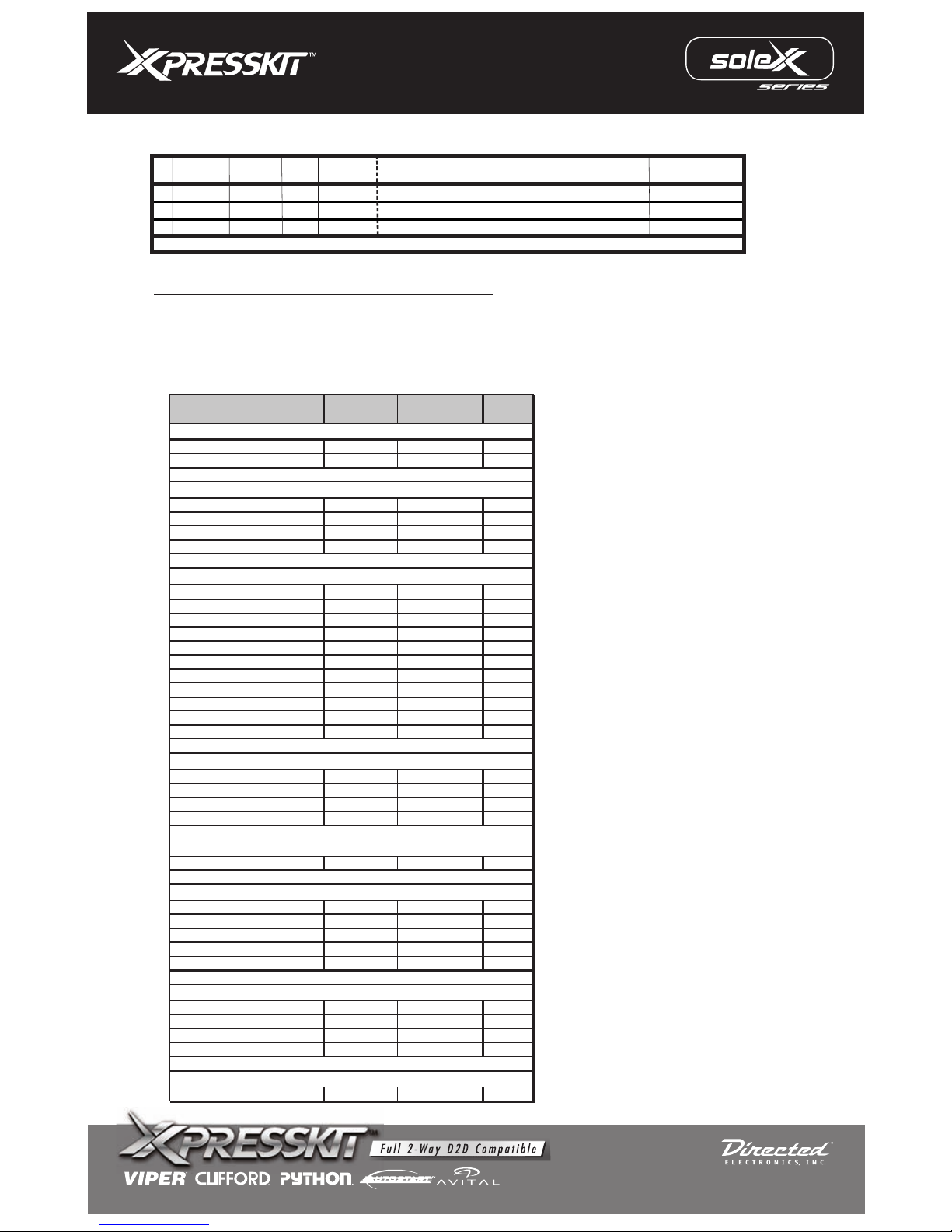
Vehicle Wiring Reference Chart
Model Year
Resistor
Code
Voltage
Reference Ignition
Enclave 2008 White White/Black Pink
Lucerne 2006-2008 White White/Black Pink
CTS 2008 White White/Black Pink
DTS 2006-2007 White White/Black Pink
Escalade 2007-2008 Pink/Black White Pink
SRX 2007-2008 White White/Black Pink
Avalanche 2007-2008 Pink/Black White Pink
Cobalt 2006-2008 White White/Black Yellow
Equinox 2007-2008 White White/Black Pink
Express Van 2008 Pink White Pink
HHR 2006-2008 White White/Black Yellow
Impala 2006-2008 White White/Black Pink
Malibu 2004-2008 White White/Black Pink
Monte Carlo 2006-2007 White White/Black Pink
Silverado 2007-2008 Pink/Black White Pink
Suburban 2007-2008 Pink/Black White Pink
Tahoe 2007-2008 Pink/Black White Pink
Acadia 2007-2008 White White/Black Pink
Savana Van 2008 Pink White Pink
Sierra 2007-2008 Pink/Black White Pink
Yukon 2007-2008 Pink/Black White Pink
H2 2008 Pink/Black White Pink
G5 2007-2008
White White/Black Yellow
G6 2005-2008 White White/Black Pink
Pursuit G5 2006-2008 White White/Black Yellow
Solstice 2006-2008 White White/Black Yellow
Torrent 2007-2008 White White/Black Pink
Aura 2007-2008 White White/Black Pink
Outlook 2007-2008 White White/Black Pink
Sky 2007-2008 White White/Black Yellow
VUE 2008 White White/Black Pink
XL7 2007-2008 White White/Black Pink
Buick
Cadillac
Chevrolet
GMC
Suzuki
HUMMER
Pontiac
Saturn
Page 8 to 8
MODEL: pkucg2x
Rev.: 20091028
© 2008 Directed Electronics. All rights reserved.
Page 11
MODEL: pkucg2x
Rev.: 20091028
© 2008 Directed Electronics. All rights reserved.
Page 12
LIMITED ONE-YEAR CONSUMER WARRANTY
For a period of ONE YEAR from the date of purchase of a Directed Electronics remote start or security
product, Directed Electronics. (“DIRECTED”) promises to the original purchaser, to repair or replace with
a comparable reconditioned piece, the security or remote start accessory piece (hereinafter the “Part”),
which proves to be defective in workmanship or material under normal use, provided the following
conditions are met: the Part was purchased from an authorized DIRECTED dealer; and the Part is
returned to DIRECTED, postage prepaid, along with a clear, legible copy of the receipt or bill of sale
bearing the following information: consumer’s name, address, telephone number, the authorized
licensed dealer’s name and complete product and Part description.
This warranty is nontransferable and is automatically void if the Part has been modified or used in a
manner contrary to its intended purpose or the Part has been damaged by accident, unreasonable use,
neglect, improper service, installation or other causes not arising out of defect in materials or
construction.
TO THE MAXIMUM EXTENT ALLOWED BY LAW, ALL WARRANTIES, INCLUDING BUT NOT
LIMITED TO EXPRESS WARRANTY, IMPLIED WARRANTY, WARRANTY OF MERCHANTABILITY,
FITNESS FOR PARTICULAR PURPOSE AND WARRANTY OF NON INFRINGEMENT OF
INTELLECTUAL PROPERTY, ARE EXPRESSLY EXCLUDED; AND DIRECTED NEITHER ASSUMES
NOR AUTHORIZES ANY PERSON OR ENTITY TO ASSUME FOR IT ANY DUTY, OBLIGATION OR
LIABILITY IN CONNECTION WITH ITS PRODUCTS. DIRECTED HEREBY DISCLAIMS AND HAS
ABSOLUTELY NO LIABILITY FOR ANY AND ALL ACTS OF THIRD PARTIES INCLUDING DEALERS
OR INSTALLERS. IN THE EVENT OF A CLAIM OR A DISPUTE INVOLVING DIRECTED OR ITS
SUBSIDIARY, THE PROPER VENUE SHALL BE SAN DIEGO COUNTY IN THE STATE OF
CALIFORNIA. CALIFORNIA STATE LAWS AND APPLICABLE FEDERAL LAWS SHALL APPLY AND
GOVERN THE DISPUTE. THE MAXIMUM RECOVERY UNDER ANY CLAIM AGAINST DIRECTED
SHALL BE STRICTLY LIMITED TO THE AUTHORIZED DIRECTED DEALER’S PURCHASE PRICE
OF THE PART. DIRECTED SHALL NOT BE RESPONSIBLE FOR ANY DAMAGES WHATSOEVER,
INCLUDING BUT NOT LIMITED TO, ANY CONSEQUENTIAL DAMAGES, INCIDENTAL DAMAGES,
DAMAGES FOR THE LOSS OF TIME, LOSS OF EARNINGS, COMMERCIAL LOSS, LOSS OF
ECONOMIC OPPORTUNITY AND THE LIKE. NOTWITHSTANDING THE ABOVE, THE
MANUFACTURER DOES OFFER A LIMITED WARRANTY TO REPLACE OR REPAIR AT
DIRECTED’S OPTION THE PART AS DESCRIBED ABOVE.
Some states do not allow limitations on how long an implied warranty will last or the exclusion or
limitation of incidental or consequential damages. This warranty gives you specific legal rights and
you may also have other rights that vary from State to State. DIRECTED does not and has not
authorized any person or entity to create for it any other obligation, promise, duty or obligation in
connection with this Part.920-0007 07-06
PROTECTED BY U.S. PATENTS: 5,719,551; 6,011,460 B1 *;6,243,004 B1; 6,249,216 B1; 6,275,147 B1; 6,297,731 B1; 6,346,876 B1; 6,392,534 B1; 6,529,124 B2; 6,696,927 B2; 6,756,885 B1; 6,756,886 B2;
6,771,167 B1; 6,812,829 B1; 6,924,750 B1; 7,010,402 B1; 7,015,830 B1; 7,031,826 B1; 7,046,126 B1; 7,061,137 B1; 7,068,153 B1; 7,205,679 B1; CDN. PATENT: 2,320,248; 2,414,991; 2 , 4 1 5 , 0 1 1 ;
2,415,023; 2,415,027; 2,415,038; 2,415,041; 2,420,947; 2,426,670; 2,454,089 EUROPEAN PATENT:1,053,128 PAT. PENDING: 2,291,306; MADE IN CANADA
This Interface kit / Data Bus Interface part has been tested on the
listed vehicles. Other vehicles will be added
to the select vehicle list upon completion of compatibility testing. Visit website for latest vehicle application
guide. DISCLAIMER: Under no circumstances shall the manufacturer or the distributors of the bypass kit /
data bus interface part(s) be held liable for any
consequential damages sustained in connection with the
part(s) installation. The manufacturer and it’s distributors will not, nor will they authorize any
representative
or any other individual to assume obligation or liability in relation to the
interface kit / data bus interface part(s)
other than its replacement. N.B.:Under no circumstances shall the manufacturer and distributors
of this
product be
liable for consequential damages sustained in connection with this product and neither assumes
nor authorizes any representative or other person to assume for it any obligation or liability other than the
replacement of this product only.
MODEL: pkucg2x
Rev.: 20091028
© 2008 Directed Electronics. All rights reserved.
 Loading...