

Page 1
Platform: DBALL2
Firmware: MRC01
Update Alert: Firmware updates are posted to the web on a regular basis. We recommend
that you check for firmware and/or install guide updates prior to installing this product.
Installation Guide
The DBALL2-MRC01 is a door lock and key Interface compatible with the Mercedes Benz cars. Features
include door locks, turn signals, windows and sunroof, door trigger sensing, hood pin, trunk/hatch, ignition
and tach output.
Rev.: 20150626
Index
Vehicle Application Guide................................................................................................................................................
Installation
Wiring Diagram ...............................................................................................................................................................
Can Location....................................................................................................................................................................
Programming
Module Programming......................................................................................................................................................
Feature & Option List.......................................................................................................................................................
Feature Programming......................................................................................................................................................
LED Diagnostics and Troubleshooting.............................................................................................................................
Warranty...........................................................................................................................................................................
02
03
04
05
06
06
07
08
† Mercedes-Benz is registered trademarks and property of their respective companies.
© 2014 Directed. All rights reserved.
Page 2
Platform: DBALL2
Firmware: MRC01
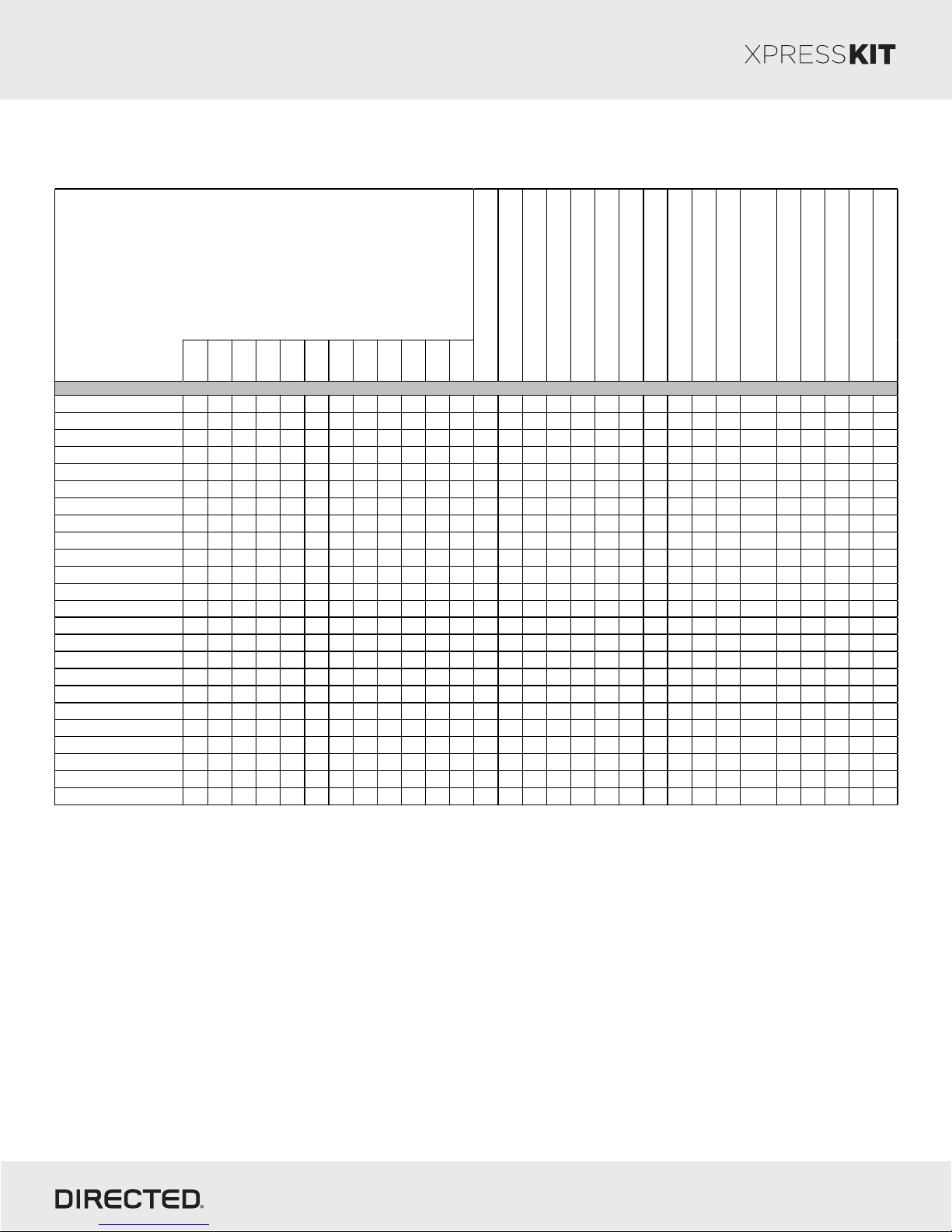
Vehicle Application Guide
Vehicle Years & Installation Type
2015
2014
2013
2012
2011
MERCEDES
A-Class (W 169)
A-Class (W 176)
B B B • • • • • • • D • • • D D
B-Class (W 245)
B-Class (W 246)
B B B B • • • • • • • D • • • D D
C-Class (W 203)
C-Class (W 204)
CL-Class (C216)
CLA-Class (C117)
B B B • • • • • • • D • • • D D
CLC-Class (CL203)
CLK-Class (W209)
CLK-Class (C207)
CLS-Class (W219)
CLS-Class (W218)
B B B B • • • • • • • • • • D • • • D D
E-Class (W 211)
E-Class (W 212)
G-Class (W 643)
B B B B B B B • • • • • • • • • • • D • • • D D
B B B • • • • • • • D • • • D D
GL-Class (X164)
GLK-Class (X204)
B B B B B B • • • • • • • • • • • D • • • D D
ML-Class (W164)
ML-Class (W166)
R-Class (V251)
B B B • • • • • • • D • • • D D
A A A A A A A A A A • • • • • • • • • • • D • • • D D
S-Class (W 221)
Vito
Viano
* - available only in trigger or warning mode
D: Data-to-Data (D2D) only
•: D2D and Wire-to-Wire (W2W)
A A A A A A A A A • • • • • • • D • • • D D
A A A A A A A A A • • • • • • • D • • • D D
AV: Horn & Lights Control
CC: Comfort & Convenience Controls
A A A A A A A A • • • • • • • D • • • D D
A A A A A A A • • • • • • • • • D • • • D D
B B B B B B B • • • • • • • • • • • D • • • D D
B B B B B B B B • • • • • • • • • • • D • • • D D
A A A A • • • • • • • • • • • D • • • D D
B B B B • • • • • • • • • • • D • • • D D
A A A A A A A • • • • • • • • • • • D • • • D D
A A A A A A A • • • • • • • • • • • D • • • D D
A A A A A A • • • • • • • • • • • D • • • D D
B B B B B B B B • • • • • • • • • • • D • • • D D
Rev.: 20150626
2010
2009
2008
2007
2006
2005
2004
AV- Turn Signal Control ON/OFF*
CC- Power Windows Rollup
CC- Power Windows Rolldown
CC- Sunroof closure
CC- Comfort Closure
DL- Arm Factory Security
DL- Disarm Factory Security
DL- Door Lock Control
DL- Door Unlock ALL doors
DL- Door Unlock Driver Priority
A A • • • • • • • • • • • D • • • D D
A A A A A • • • • • • • • • • • D • • • D D
A A A A A • • • • • • • • • • • D • • • D D
DL: OE Door Lock & Alarm Controls
RS: Engine Start & Status
SS: Entry Point Status-Security
ST: Function/Feature Status
FOB-Control of aftermarket alarm
with OEM remote
SS- Entry Status ALL Door Pins
SS- Entry Status Hood Pin
DL- Trunk / Hatch Release
SS- Entry Status Trunk/Hatch Pin
Page 2
SS- Entry Status Drivers Door Pin
MC - Keysense Status
© 2014 Directed. All rights reserved.
Page 3
Platform: DBALL2
Firmware: MRC01
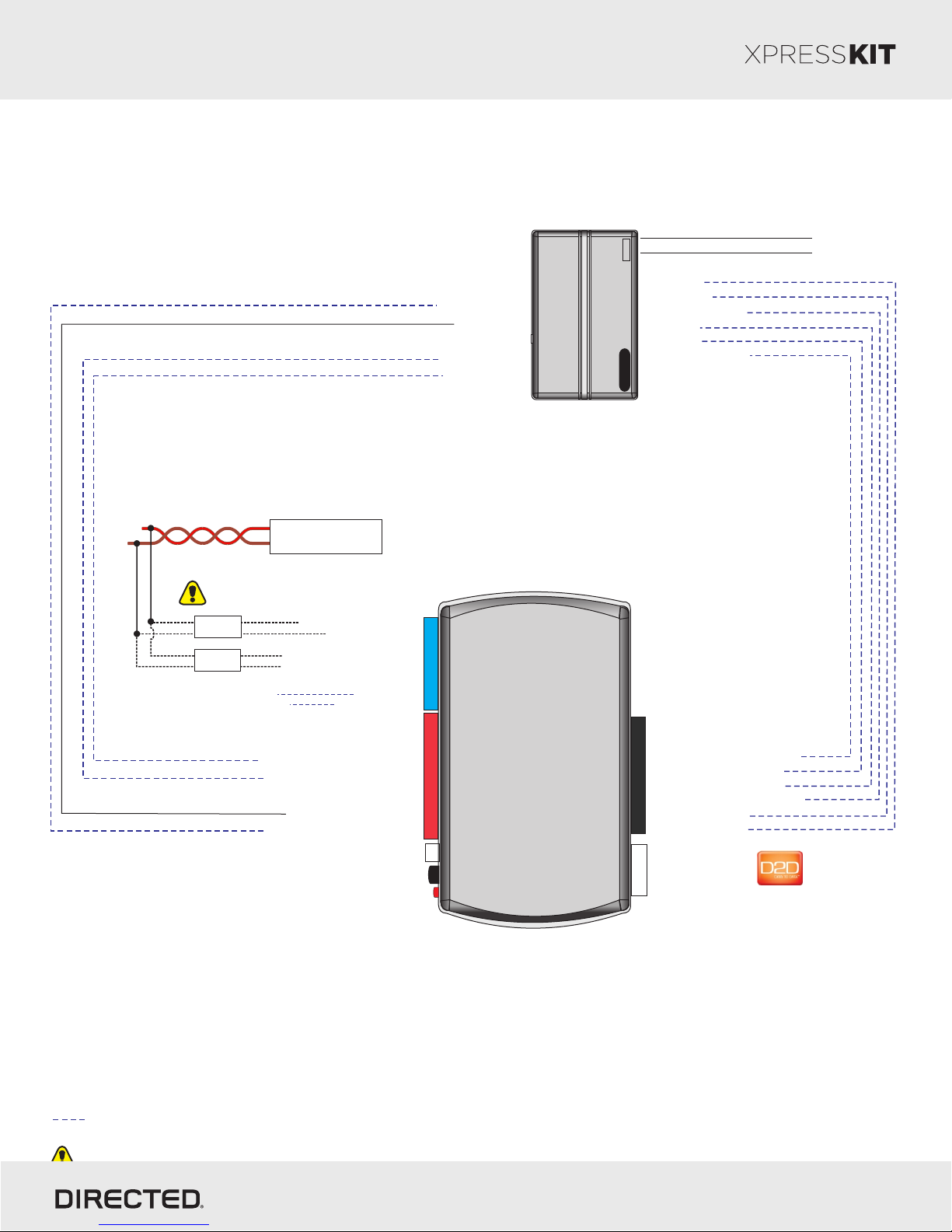
Installation Wiring Diagram
Twisted pair in driver kick panel or
driver side under dashboard
(see page 4 for CAN location)
CAN High: Brown/Red
CAN Low: Brown
(-) Hood Status Input
(+) Ignition Input
(-) Trunk Status Input
(-) Door Status Input
Security
System
(-) Lock Output
(-) Unlock Output
(-) Trunk Release Output
Aux 1 Output
Aux 2 Output
(+) Parking Lights Output
Rev.: 20150626
Page 3
(+) 12 V
(-) Ground
See VAG
on page 2
Type B
OR
Type A
3: Tan/Black: HS CAN High
4: Tan: HS CAN Low
5: Orange/Green: FT C AN High
6: Orange/Brown: FT C AN Low
(+) 12v
(-) Ground
3: Green/White: (-) Door Status Output
4: Red/Black: (-) Trunk Status Output
7: Gray/Black: (+) Ignition Output
12: Blue/Red: (-) Hood Status Output
13: Red: (+) 12v
14: Black: (-) Ground
14
122
RF Loop connector
Programming button
LED
DBALL
7: Pink/White: (+) Parking Lights Input
5: Violet/Black: (-) AUX2 Input*
10
4: White/Violet: (-) AUX1 Input*
3: Red/White: (-) Trunk Release Input
2: Blue: (-) Unlock Input
1: Green: (-) Lock Input
(+)12v
RX
4
(-) Ground
TX
P#: XKD2D65
Not required in D2D mode.
* See Feature and Option list to know Auxiliary Channel programming options
Wires are listed by pin numbers. This display is not representative of connector pin layouts, which are often stacked.
© 2014 Directed. All rights reserved.
Page 4
Platform: DBALL2
Firmware: MRC01
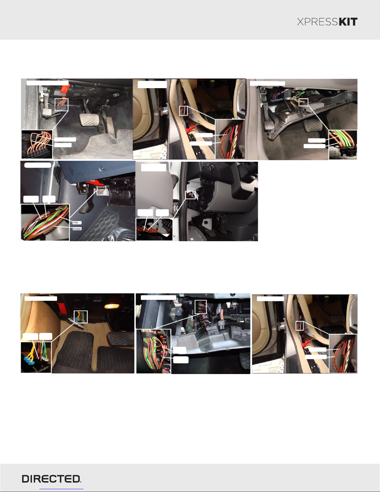
Can Location for TYPE A
Rev.: 20150626
Page 4
Mercedes C (up to 2007)/CLC/CLK
Mercedes Vito/Viano
Can H:
Brown/Red
Can L:
Brown
Can H: Brown/Red
Can L: Brown
Mercedes ML/GL/R
Mercedes Sprinter
Volkswagen Crafter
Can H:
Brown/Red
Can L:
Brown
Can L: Brown
Can H: Brown/Red
Mercedes E (W211)/CLS
Can L: Brown
Can H: Brown/Red
Can Location for TYPE B
Mercedes S/CL Class
Can L:
Can H:
Brown
Brown/Red
Mercedes C (2007 - up)/GLK
Can L:
Brown
Can H:
Brown/Red
Mercedes E (W212)
Can L: Brown
Can H: Brown/Red
© 2014 Directed. All rights reserved.
Page 5
Platform: DBALL2
Firmware: MRC01
Module Programming
Rev.: 20150626
Page 5
1
2a
2b
3
4
5
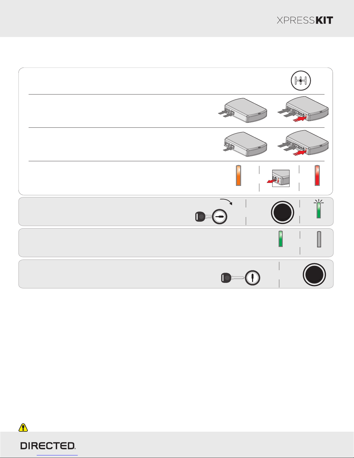
Please ensure that the vehicle is in a safe location and cannot move forward during
programming. For vehicles equipped with a manual transmission, ensure the gearshift
lever is in the neutral position.
If using in D2D: Connect the 10-pin, 12-pin & 14-pin
harnesses to the module. Press & hold the Programming
button, then connect the 4-pin D2D harness.
If using in W2W: Connect the 10-pin & 12-pin harnesses to
the module. Press & hold the Programming button, then
connect the 14-pin harness to the module.
D2D
10-pin
th
5
st
1
D2D
10-pin
st
1
Wait until the LED turns ON orange then release the
or
&
x2
Programming button. The LED turns ON red.
Turn ON Ignition using Key or
Push-to-Start (PTS) button.
Key
Solid Orange
OFF
N
G
I
START
The LED turns ON solid green for 3 seconds, then turns OFF
once the module has been successfully programmed.
rd
3
nd
2
4
th
4
nd
2
3
Release
START
STOP
E
E
N
N
I
G
Solid Green
x3 secs
14-pin
12-pin
th
14-pin
12-pin
rd
&
&
&
3 51
4 R2
Solid Red
Flashes
OFF
OFF
IGN
START
6
Turn the Ignition OFF.
Key OUT
Module reset will be done automatically upon programming.
Refer to the LED Diagnostics section on page 8 for more information and for troubleshooting purposes.
or
x1
START
STOP
E
N
I
G
E
N
© 2014 Directed. All rights reserved.
Page 6
Fea t. Operation Flashes/Options Description
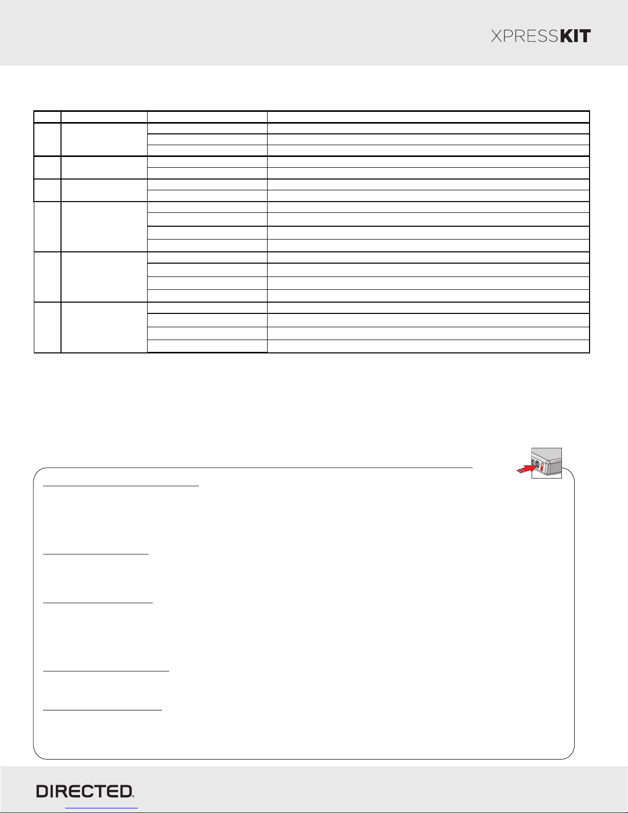
1. No RF Output*
Module is connected to a remote starter using a s tandard ins tallation.
2. SmartStart
Module is connected to SmartStart using an RSR or RXT installation (when available).
3. RFTD Output Module is connected to an XL202 us ing an RSR or RXT installation (when available).
1. Driver Priority
2. Unlock All*
1. Disabled*
2. Enabled
1. OFF*
2. Windows Roll Up
3. Windows Roll Down
4. Gas Cap Open
1. OFF*
2. Windows Roll Up
3. Windows Roll Down
4. Gas Cap Open
1. OFF*
2. Windows Roll Up
3. Windows Roll Down
4. Gas Cap Open
RFTD Output Type1
3 Comfort Closure
6 AUX 3
AUX 14
5 AUX 2
2
Unlock Driver
Priority
Platform: DBALL2
Firmware: MRC01
Feature and Option List
Rev.: 20150626
Page 6
* Default Option
Feature Programming
To enter feature programming routine
Use the key to turn the ignition ON, then OFF.
Within 5 sec, press and HOLD the Programming button. The orange LED turns ON after 3 seconds. Release the Programming
button.
The green LED starts flashing slowly one time to indicate the feature number is 1. After a short delay, the red LED flashes rapidly
to indicate the current option of feature 1. It repeats until next action happens.
Changing feature options
Press the lock/arm or unlock/disarm button on aftermarket transmitter to change the option of the selected feature.
The red LED flashes rapidly the number of times equal to the current option number. After a short delay, the green LED flashes
slowly the number of times to indicate the current feature. It repeats until next action happens.
Accessing another feature
Press and release the Programming button a number of times to advance from the current feature to the next desired feature.
The green LED flashes slowly the number of times equal to the feature number. After a short delay, the red LED flashes rapidly to
indicate the current option of the current feature. It repeats until next action happens.
When the maximum number of feature or option is reached, the LED will starts flashing again from the first feature or option.
Once a feature is programmed
Another feature(s) can be programmed.
The feature programming can be exited.
Exiting feature programming
No activity for 30 seconds; after 30 seconds, the orange LED will turn ON for 2 seconds to confirm exiting.
OR
Press and HOLD the Programming button for 3 seconds. After 3 seconds, the orange LED will turn ON for 2 seconds to confirm
exiting.
Programming
Button
© 2014 Directed. All rights reserved.
Page 7
Platform: DBALL2
Firmware: MRC01
LED Diagnostics and Troubleshooting
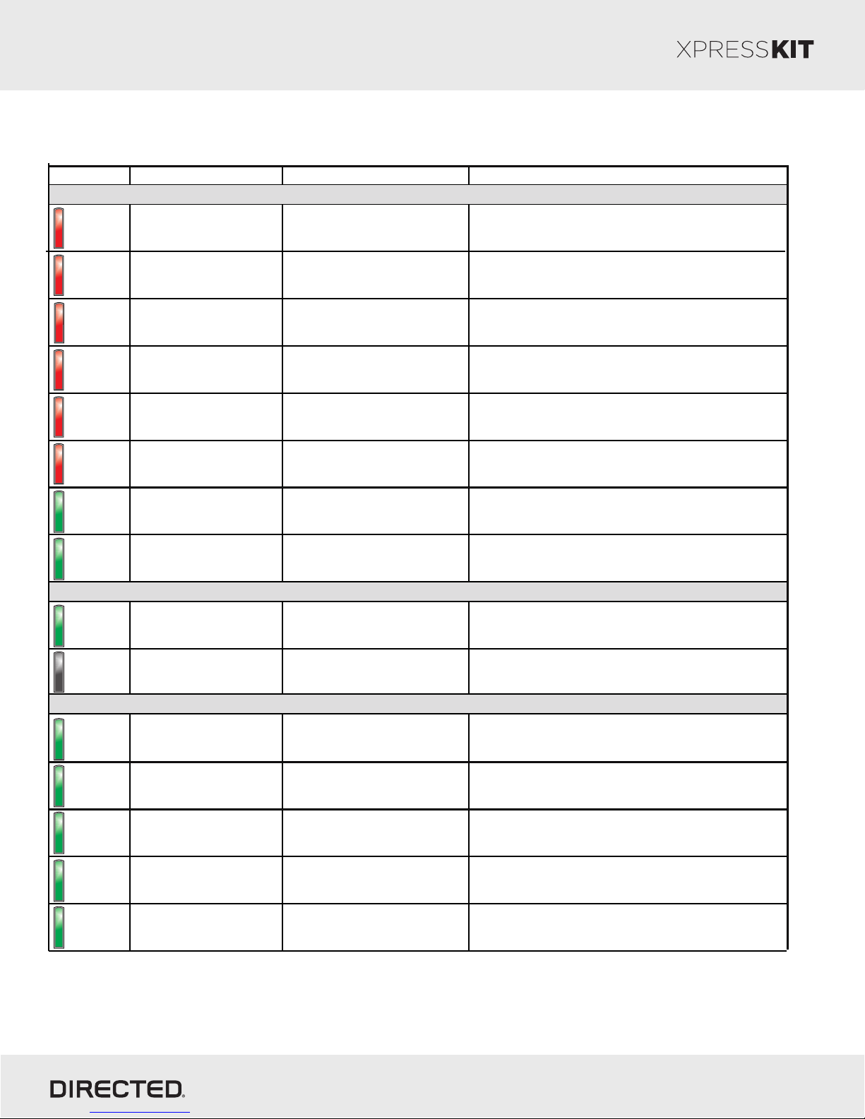
LED Status Description Troubleshooting
Module Programming
Solid
Solid red.
Waiting for the vehicle to be
started.
Make sure that all the connections are correct (see
install sheet) and turn the ignition ON to begin the
programming sequence.
Rev.: 20150626
Page 7
Solid x30 secs
Flashes x1
Solid x30 secs
Flashes x2
Solid x30 secs
Flashes x3
Solid x30 secs
Flashes x4
Solid x30 secs
Flashes x5
Flashes
Solid x3 secs
Solid red for 30 seconds,
then flashes once.
Solid red for 30 seconds,
then flashes twice.
Solid red for 30 seconds,
then flashes 3 times.
Solid red for 30 seconds,
then flashes 4 times.
Solid red for 30 seconds,
then flashes 5 times.
Flashes green
continuously.
Solid green for 3 seconds.
Active Ground W hile Running
Flashes
Off
Flashes green
continuously.
Off. N/A.
Inactive Ground While Running
Flashes x1
Flashes x2
Flashes x3
Flashes x4
Flashes x5
Flashes green once.
Flashes green twice.
Flashes green 3 times.
Flashes green 4 times.
Flashes green 5 times.
FT CAN not detected.
HS CAN not detected.
The CA N wires may be incorrectly connected. Refer to
the wiring diagram to make the right connections.
The CA N wires may be incorrectly connected. Refer to
the wiring diagram to make the right connections.
The CA N bus was detected but the ignition on CA N
Invalid CA N network.
message is not detected. Check if the firmware from
unit is correct.
Invalid V IN.
The V IN number is invalid. Report the issue to technical
support.
Internal error. Report the issue to technical support.
Vehicle has been successfully
detected.
Module has been successfully
programmed.
N/A.
N/A.
Ground out (GWR) is active. N/A.
The Ground While Running (status) wire is incorrectly
connected. Refer to the wiring diagram to make the right
connections.
Lock command has been
received.
Unlock command has been
received.
Trunk release command has
been received.
Aux 1 command has been
received.
Aux 2 command has been
received.
If it does not flash, the bypass module did not receive the
signal. Verify the connections between the bypass and
the remote starter module.
If it does not flash, the bypass module did not receive the
signal. Verify the connections between the bypass and
the remote starter module.
If it does not flash, the bypass module did not receive the
signal. Verify the connections between the bypass and
the remote starter module.
If it does not flash, the bypass module did not receive the
signal. Verify the connections between the bypass and
the remote starter module.
If it does not flash, the bypass module did not receive the
signal. Verify the connections between the bypass and
the remote starter module.
© 2014 Directed. All rights reserved.
Page 8
Platform: DBALL2
Firmware: MRC01
Rev.: 20150626
Page 8
Limited One-Year Consumer Warranty
For a period of ONE YEAR from the date of purchase of a Directed Electronics remote start or security product, Directed
Electronics. (“DIRECTED”) promises to the original purchaser, to repair or replace with a comparable reconditioned piece, the
security or remote start accessory piece (hereinafter the “Part”), which proves to be defective in workmanship or material
under normal use, provided the following conditions are met: the Part was purchased from an authorized DIRECTED dealer;
and the Part is returned to DIRECTED, postage prepaid, along with a clear, legible copy of the receipt or bill of sale bearing the
following information: consumer’s name, address, telephone number, the authorized licensed dealer’s name and complete
product and Part description.
This warranty is nontransferable and is automatically void if the Part has been modified or used in a manner contrary to its
intended purpose or the Part has been damaged by accident, unreasonable use, neglect, improper service, installation or
other causes not arising out of defect in materials or construction.
TO THE MAXIMUM EXTENT ALLOWED BY LAW, ALL WARRANTIES, INCLUDING BUT NOT LIMITED TO EXPRESS
WARRANTY, IMPLIED WARRANTY, WARRANTY OF MERCHANTABILITY, FITNESS FOR PARTICULAR PURPOSE
AND WARRANTY OF NON INFRINGEMENT OF INTELLECTUAL PROPERTY, ARE EXPRESSLY EXCLUDED; AND
DIRECTED NEITHER ASSUMES NOR AUTHORIZES ANY PERSON OR ENTITY TO ASSUME FOR IT ANY DUTY,
OBLIGATION OR LIABILITY IN CONNECTION WITH ITS PRODUCTS. DIRECTED HEREBY DISCLAIMS AND HAS
ABSOLUTELY NO LIABILITY FOR ANY AND ALL ACTS OF THIRD PARTIES INCLUDING DEALERS OR
INSTALLERS. IN THE EVENT OF A CLAIM OR A DISPUTE INVOLVING DIRECTED OR ITS SUBSIDIARY, THE
PROPER VENUE SHALL BE SAN DIEGO COUNTY IN THE STATE OF CALIFORNIA. CALIFORNIA STATE LAWS
AND APPLICABLE FEDERAL LAWS SHALL APPLY AND GOVERN THE DISPUTE. THE MAXIMUM RECOVERY
UNDER ANY CLAIM AGAINST DIRECTED SHALL BE STRICTLY LIMITED TO THE AUTHORIZED DIRECTED
DEALER’S PURCHASE PRICE OF THE PART. DIRECTED SHALL NOT BE RESPONSIBLE FOR ANY DAMAGES
WHATSOEVER, INCLUDING BUT NOT LIMITED TO, ANY CONSEQUENTIAL DAMAGES, INCIDENTAL DAMAGES,
DAMAGES FOR THE LOSS OF TIME, LOSS OF EARNINGS, COMMERCIAL LOSS, LOSS OF ECONOMIC
OPPORTUNITY AND THE LIKE. NOTWITHSTANDING THE ABOVE, THE MANUFACTURER DOES OFFER A
LIMITED WARRANTY TO REPLACE OR REPAIR AT DIRECTED’S OPTION THE PART AS DESCRIBED ABOVE.
Some states do not allow limitations on how long an implied warranty will last or the exclusion or limitation of incidental or
consequential damages. This warranty gives you specific legal rights and you may also have other rights that vary from
State to State. DIRECTED does not and has not authorized any person or entity to create for it any other obligation,
promise, duty or obligation in connection with this Part.920-0007 07-06
This
Interface kit / Data Bus
vehicle
list
upon completion
Interface part has been
of
compatibility testing.
tested on the
Visit website
listed vehicles.
for latest
vehicle
Other
vehicles
application guide.
will
be added
D
ISC
LAI
M
E
to
R:
the
select
Under
no
circumstances shall the manufacturer or the distributors of the bypass kit / data bus interface part(s) be held liable for any
consequential
will
they
bus interface
product
any
representative
PROTECTED BY U.S. PATENTS: 5,719,551; 6,011,460 B1 *; 6,243,004 B1; 6,249,216 B1; 6,275,147 B1; 6,297,731 B1; 6,346,876 B1; 6,392,534 B1; 6, 529,1 24
B2; 6,696,927 B2; 6,756,885 B1; 6,756,886 B2; 6,771,167 B1; 6,812,829 B1; 6,924,750 B1; 7,010,402 B1; 7,015,830 B1; 7,031,826 B1; 7 , 0 46 , 12 6 B1 ;
7,061,137 B1; 7,068,153 B1; 7,205,679 B1; CDN. PATENT: 2,320,248; 2,414,991; 2,415,011; 2,415,023; 2,415,027; 2,415,038; 2,415,041; 2 , 4 2 0 , 9 4 7 ;
2,426,670; 2,454,089 EUROPEAN PATENT:1,053,128 PAT. PENDING: 2,291,306; MADE IN CANADA
damages sustained
authorize
any
part(s) other than
be
liable for
or
representative or
consequential
other person to assume for it
in
connection with the
any other individual to
its
replacement. N.B.:Under no
damages sustained in
any
obligation
part(s)
installation. The
manufacturer and
assume obligation or liability in relation
circumstances shall
the
manufacturer
connection with this product and
or liability
other
than
the replacement
neither
it’
s
distributors
to
the interface
and distributors of
assumes nor
of this product
will not,
nor
kit / data
this
authorizes
only
.
© 2014 Directed. All rights reserved.
 Loading...