

Page 1
Platform: DBALL2
Firmware: MA2
Update Alert: Firmware updates are posted the web on a regular basis. We recommendon
that you check for firmware and/or install guide updates prior to installing this product.
Installation Guide
The MA2 firmware for 2 is an all-in-one door lock and override module compatible with specificDBALL
Mazda vehicles.
This module can only be flashed and configured using Xpress at www.directechs.com orVIP
using the Directechs Mobile application for smartphones. Refer to
section 20on page
for more information.
Rev.: 20170926
the Module Programming
Index
Vehicle Application Guide .....................................................................................................................................................02
Installation s s(Wiring Diagram & Vehicle Wiring Reference Chart )
Type 1...................................................................................................................................................................................03
T2ype ...................................................................................................................................................................................06
Type 3...................................................................................................................................................................................10
Type 4...................................................................................................................................................................................12
Type 5...................................................................................................................................................................................14
Type 6...................................................................................................................................................................................16
Type 7...................................................................................................................................................................................18
Programming
M ...........................................................................................................................................................20odule Programming
Method 1 (using 1 key and Key2GO) - Recommended Method ..........................................................................................21
M .......................................................................................................................................................22ethod 2 (using 2 keys)
M .................................................................................................................................................23odule Reset & Hard Reset
Web Programming for Key2GO ...........................................................................................................................................24
Feature & Option List ...........................................................................................................................................................25
Feature Programming...........................................................................................................................................................25
LED Diagnostics .....................................................................................................................................26& Troubleshooting
L ................................................................................................................................28imited One-Year Consumer Warranty
Q ........................................................................................................................................................29uick Reference Guide
® Mazda is a its respective companyregistered trademark and property of .
© 2017 Directed. All rights reserved.
Page 2
Vehicles
2016
2015
2014
2013
2012
2011
2010
2009
2008
2007
2006
2005
2004
2003
2002
PK-Immobilizer Bypass-Data No Key Req'd
CC-Power Windows Rolldown
CC-Power Windows Rollup
DL-Arm Factory Securit y
DL-Disa rm Fac tory S ecurity
DL-Door Lock Control
DL-Door Unl ock
DL-Drive r Priori ty Unlock
DL-Trunk / Hatc h Release
Key2GO
RS-Sm artStart
RS-Tach / RPM Output
SS-E ntry M onitoring A LL Door Pins
SS-E ntry M onitoring Hood P in
SS-E ntry M onitoring Trunk/Hatc h Pin
SS-Fac tory Alarm Trigger M onitoring
ST-Brak e Status (foot brake)
ST-Door Loc ks S tatus
ST-E -Brake Stat us
Mazda
2
1111 • •••••D••••D•D•
3
1111 ••••••••••D••••D•D•
3
555555 • • • •D• • • • • •
5
111111 • • • • • •D• • • •
5
55555 • • • •D• • • • • •
6
11111 ••••••••••D••••D•D•
6
222222 • • • •D• • • • • •
B-Series
333333333• •D• • • • •
CX-7
11 •••••••• •D••••D•D•
CX-7
222 • • • • D• • • • •
CX-7 (Smart Key )
111 •••••••• •D••••D•D•
CX-7 (Smart Key )
222 • • • • D• • • • •
CX-9
4444 •••••••• •D••••D•D•
CX-9
2222 • ••••D••••••
CX-9 (Smart Key )
4444 •••••••• •D••••D•D•
CX-9 (Smart Key )
2222 • ••••D••••••
MazdaS peed3
2222 • •• ••D•••• • •
MazdaS peed6
222 • •• ••D•••• • •
MX-5 Miata
2222222222 • • • • •D• • • • • •
RX-8
22222222 • • • • •D• • • • • •
Tribute 6666777 • • •D• • • • • •
Legend:
D: Data to Data (D2D) only AV: Horn &Lights Controls PK: Transponder & Immobilizer Override
•: D2D and Wire-to-Wire (W2W) DL: OE DoorLock & Alarm Controls RS:Rem ote Start& Engine Controls
FOB: SyncCAN Interface w/ FOB Remote SS: Integrated Security& Monitoring
ST:Function/Feature Status
Platform: DBALL2
Firmware: MA2
Rev.: 20170926
Page 2
Vehicle Application Guide
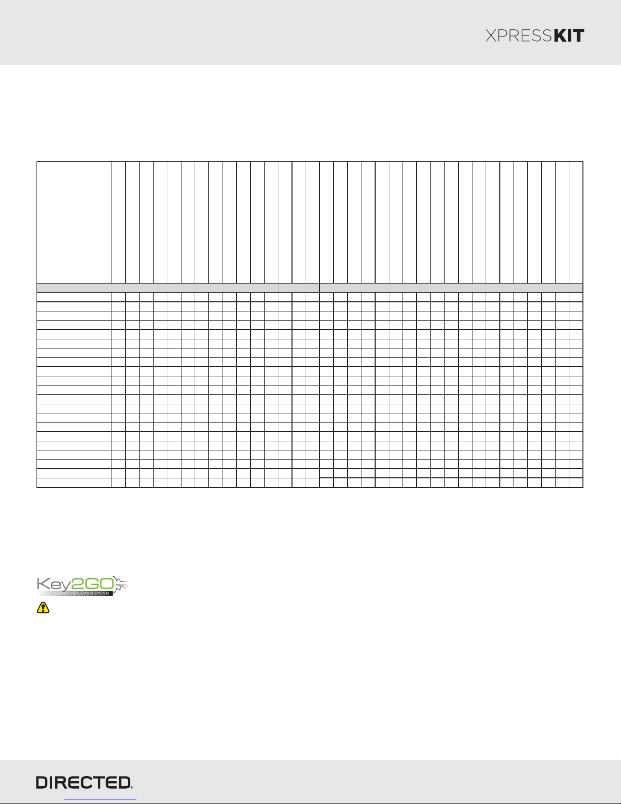
The following table lists the vehicles and features which are compatible with this product. The number assigned to each
year allows you to determine which installation type should be used for your vehicle.
This feature is required if only one key is available. You can program the interface without the need for Key2Go if two
keys are present.
Key2 has been designed and developed to bypass the advanced encryption layers found in modern vehicles. It usesGO
an array of servers to generate a duplicate of the original key, the installation of a remote starter without having toallowing
give up a key.
The advantage is that this feature allows you to use one original key and the server to configure the bypass in the vehicle.
All Key2 -compatible firmware are clearly indicated in the function list of each vehicle search result page and will alsoGO
appear on the flash page. Any first-time user must re-register to gain access to Key2 , and some additional informationGO
will be required to complete the registration process, such as your Directed account number and store name. Key2GO
requires an XKLoader.
Refer to page 19 of this guide for instructions on how to program features using Key2 .GO
© 2017 Directed. All rights reserved.
Page 3
Platform: DBALL2
Firmware: MA2
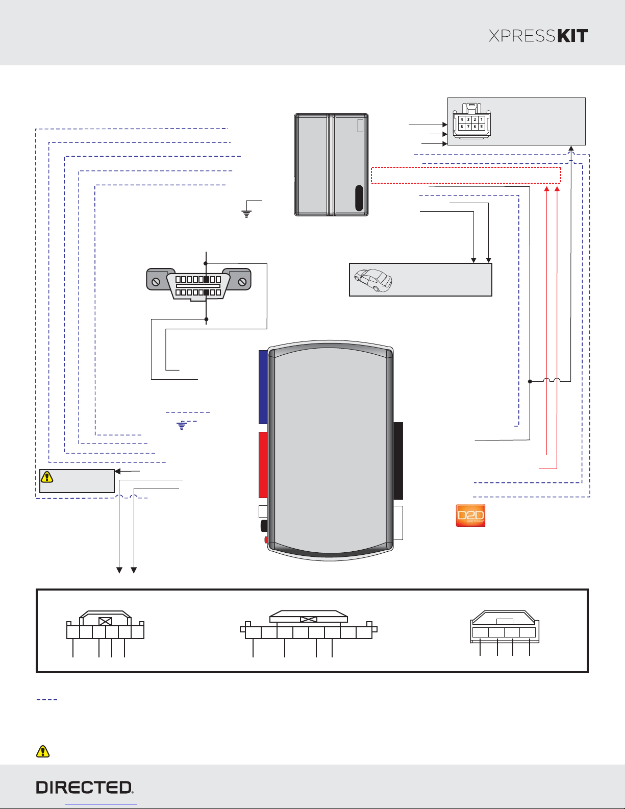
Installation Type 1
HS CA N Low: in 1P4
[]2 (-) Hood Sense Input
(+) Brake Sense Input
[]1 ( ) Tach InpuAC t
(-) Door Status Input
(-) E-Brake Sense Input
Diagnostic
connector OBD II
(connector side view)
HS CA N High: inP6
18
169
(-) Ground
Starter
Remote
Rev.: 20170926
Ignition Connector
(+) 12V Input
(+) Accessory Output
(+) Starter Output
(-) OutputLock
(-) Unl Outputock
Aux 1 & 2 Output: ONLY if equipped with front one-touch power
windows with auto up/down feature and global open.
(+) Ignition Output
(-) (Status)GWR
( utput-) Trunk Release O [3]
(-) Parking Lights
Refer to the Vehicle Wiring
Reference Chart for wire
and connector details
Refer to the Vehicle Wiring
Reference Chart for wire
and connector details.
Page 3
HS CA N High: 3Tan/Black:
HS CA N Low: 4Tan:
(+) 12V: 13Red:
(-) Ground: 14Black:
Data : 10TX Yellow/Black:
Data : 11RX Orange/Black:
See Reference
Chart for Door Lock
MUX wire in vehicle.
(+) 12V
(-) E-Brake Status Output: 1Black/White:
(-) Door Status Output: 3Green/White:
[]1 ( ) Tach Output: 5AC Violet/White:
(+) Brake Status Output: 6Gray:
( ) Door Lock Output: 9MUX Violet/Brown:
[]2 (-) Hood Status Output: 12Blue/Red:
Passive Anti-Theft Security System ( ) connectorsPATS
A
6
5
Ground RX TX Ignition
1234
14
10: (-) (Status) InputBlue/White: GWR
9: (+) Ignition InputPink:
10
12
2
RF
Prog Button.
LED
B
6
7
8
Ground RX TXIgnition
4321
5
5: (-) Power ll-down InputViolet/Black: Windows Ro
4: (-) Power ll-up InputWhite/Violet: Windows Ro
2: (-) Unlock InputBlue:
1: (-) Lock InputGreen:
(+)12V
4
RX
2DBALL
(-) Ground
TX
P#: 2D65XKD
Ignition
4
C
3
Ground
TX
2
1
RX
Not required in D2D mode.
[1] Tach wire is an optional connection required on some remote starters, which do not support a tach signal in D2D.
[2] Only if vehicle is equipped with OEM hood pin.
[]3 Trunk release output is ONLY required if trunk is not supported in data.
Unless specified otherwise, all connectors are displayed from the wire side, with the exception of the diagnostic connector.OBDII
© 2017 Directed. All rights reserved.
Page 4
Platform: DBALL2
Function Wire Color Pin Pola rity Location
Color Pins
Mazda 2 2011-2014
12V Red 3 (+) Ignition switch. White 6
Ignition Black/Yellow 5 (+) Ignition s witc h. White 6
Accessory Black/Red 1 (+) Ignition switch. White 6
Starter Blac k/Blue 2 (+) Ignition switch. White 6
HS CAN High Red 6 Data OBDII. Blac k 16
HS CAN Low Blue 14 Data OBDII. Black 16
RX Gray 4 Data
Immobilizer Module around ignition swit ch.
(PATS c onnector A).
White 6
TX Green 3 Data
Immobilizer Module around ignition swit ch.
(PATS c onnector A).
White 6
Parking Light Brown/W hite 8 (-) Headlight switch. W hite 12
Trunk Release Orange/Blue 2 5-Wire BCM behind glove box. Gray 16
Door Lock (W O/Alarm) Pink 20 MUX BCM behind glove box . Gray 24
Door Lock (W /Alarm) Green 2 MUX BCM behind glove box. Gray 24
Mazda 3 2010-2013
12V Orange 8 (+) Ignition s witc h. W hite 8
Ignition Blue 1 (+) Ignition switch. W hite 8
Accessory White 6 (+) Ignition switch. White 8
Starter Lt. Green 5 (+) Ignit ion s witc h. W hite 8
HS CAN High White 6 Data OBDII. Black 16
HS CAN Low Red 14 Data OBDII. Black 16
RX Blue 1 Data
Immobilizer Module around ignition swit ch.
(PATS c onnector C).
White 4
TX Lt. B lue 2 Dat a
Immobilizer Module around ignition swit ch.
(PATS c onnector C).
White 4
Parking Light Gray 23 (-) BCM Above Driver kic k panel. White 24
Trunk Release Brown 8 (-) BCM Above Driver k ick panel. White 24
Door Lock (W O/Alarm) Lt. Green 14 MUX BCM Above Driver k ick panel. White 24
Door Lock (W /Alarm) Green 13 MUX BCM Above Driver k ick panel. White 24
Mazda 5 2011-2016
12V Blue/Blac k 8 (+) Ignition switch. White 8
Ignition Blue 1 (+) Ignition switch. W hite 8
Accessory Black/Red 6 (+) Ignition switch. White 8
Starter Blue/Red 5 (+) Ignition swit ch. White 8
HS CAN High Green/Yellow 6 Data OBDII. Blac k 16
HS CAN Low Red/Yellow 14 Data OBDII. Black 16
RX Gray 1 Data
Immobilizer Module around ignition swit ch.
(PATS c onnector C).
White 4
TX Blue/Orange 2 Data
Immobilizer Module around ignition swit ch.
(PATS c onnector C).
White 4
Parking Light Brown/Red 23 (-) BCM behind glove box. Blue 24
Trunk Release Violet/Yellow 8 (-) BCM behind glove box. White 24
Door Lock (W /Alarm) Blue 14 MUX BCM behind glove box. Whit e 24
Wire Information
Connector Information
Firmware: MA2
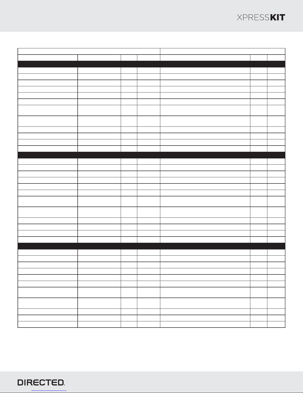
Type 1 - Vehicle Wiring Reference Chart
Rev.: 20170926
Page 4
© 2017 Directed. All rights reserved.
Page 5
Platform: DBALL2
Wire Information Connector Information
Function Wire Color Pin Polarity Location
Color Pins
Mazda 6 2009-2013
12V Red/Blue 6 (+) Ignition switch. White 6
Ignition Green/Yellow 2 (+) Ignition switch. W hite 6
Accessory Pink /Yellow 4 (+) Ignition switch. White 6
Starter Gray /Red 1 (+) Ignition s witch. White 6
HS CAN High Gray/Red 6 Data OBDII. Black 16
HS CAN Low Blue/Red 14 Data OBDII. Black 16
RX W hite/Green 3 Data
Immobilizer Module around ignition switch.
(PATS c onnector B).
White 8
TX Gray/Orange 4 Data
Immobilizer Module around ignition switch.
(PATS c onnector B).
White 8
Parking Light Black /White 14 (-) Headlight s witc h. White 17
Trunk Release Blac k/Red 28 (-) BCM Above Driver k ick panel. White 30
Door Lock (W O/Alarm) Black/W hite 4 MUX BCM Above Driver k ick panel. White 16
Door Lock (W /Alarm) Black 14 MUX BCM Above Driver kick panel. White 16
Mazda CX-7 2010-2011
12V Red 6 (+) Ignition switch. White 6
Ignition Dk. Green/Yellow 2 (+) Ignition switch. White 6
Accessory Pink /Yellow 4 (+) Ignition switch. White 6
Starter Gray /Red 1 (+) Ignition switch. White 6
HS CAN High Gray/Dk. Blue 6 Dat a OBDII. Black 16
HS CAN Low Dk. Blue/White 14 Data OBDII. Black 16
RX W hite/ Dk. Green 1 Data
Immobilizer Module around ignition switch.
(PATS c onnector C).
White 4
TX Gray/Orange 2 Data
Immobilizer Module around ignition switch.
(PATS c onnector C).
White 4
Parking Light Black /Dk. Blue 14 (-) Headlight s witch. White 17
Trunk Release Blac k/Red 17 (-) BCM Above Driver k ick panel. White 30
Door Lock (W O/Alarm) Green/Red 14 MUX BCM Above Driver k ick panel. W hite 30
Door Lock (W /Alarm) Black /W hite 11 MUX BCM Above Driver kick panel. White 30
Mazda CX-7 2010-2012 (Smart Key)
12V Red 6 (+) Ignition switch. White 6
Ignition Dr. Green/Yellow 2 (+) Ignition switch. White 6
Accessory Pink /Yellow 4 (+) Ignition switch. White 6
Starter Gray /Red 1 (+) Ignition switch. White 6
HS CAN High Gray/Dk. Blue 6 Dat a OBDII. Black 16
HS CAN Low Dk. Blue/White 14 Data OBDII. Black 16
RX W hite/ Dk. Green 1 Data
Immobilizer Module around ignition switch.
(PATS c onnector C).
White 4
TX Gray/Orange 2 Data
Immobilizer Module around ignition switch.
(PATS c onnector C).
White 4
Parking Light Black /Dk. Blue 14 (-) Headlight s witch. White 17
Trunk Release Blac k/Red 17 (-) BCM Above Driver k ick panel. White 30
Door Lock (W O/Alarm) Green/Red 14 MUX BCM Above Driver k ick panel. W hite 30
Door Lock (W /Alarm) Black /W hite 11 MUX BCM Above Driver kick panel. White 30
Firmware: MA2
Type 1 - Vehicle Wiring Reference Chart
Rev.: 20170926
Page 5
© 2017 Directed. All rights reserved.
Page 6
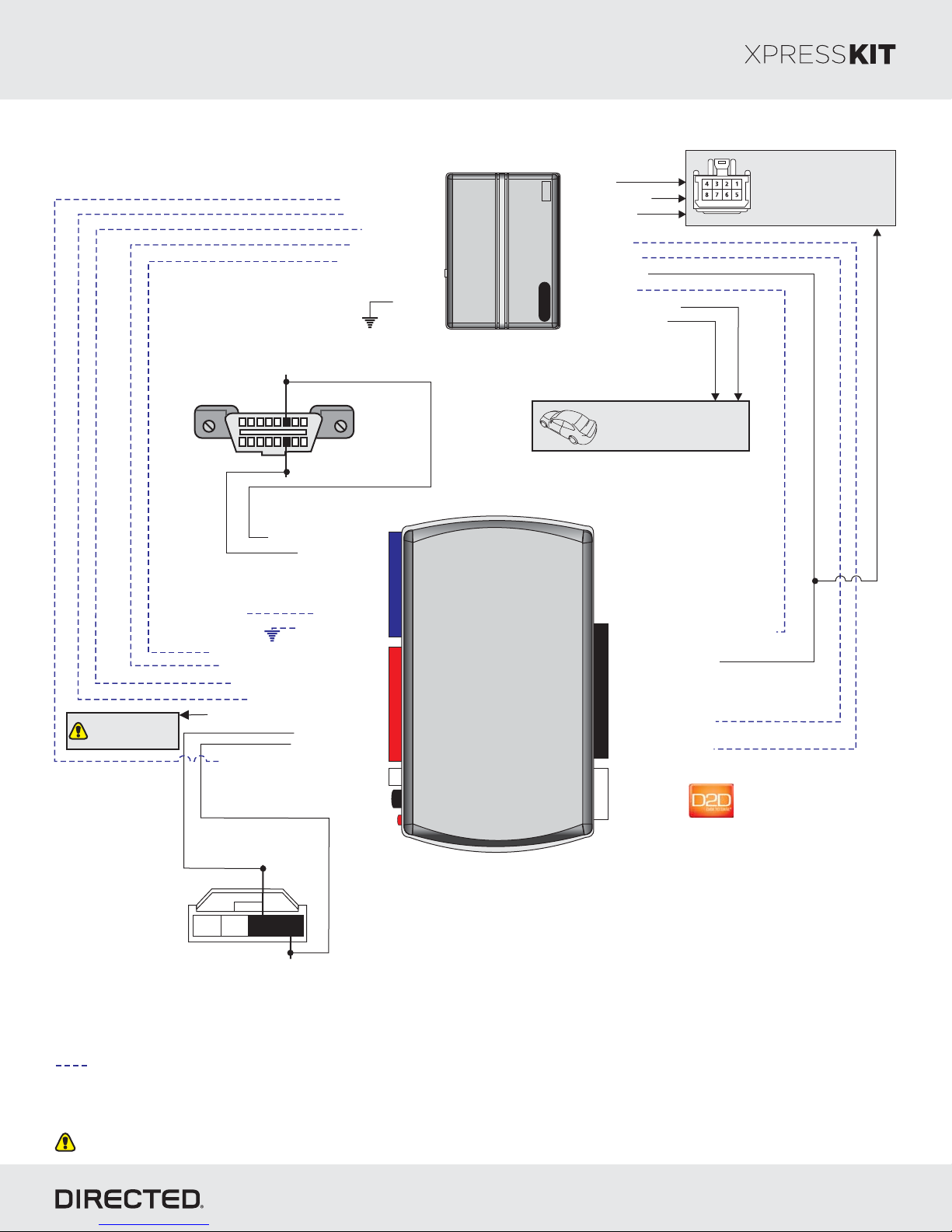
Platform: DBALL2
Firmware: MA2
Installation Type 2
Rev.: 20170926
Page 6
See Reference
Chart for Door Lock
wire in vehicle.MUX
[]2 (-) Hood Status Input
(+) Brake Status Input
[]1 ( ) Tach InpuAC t
(-) Door Status Input
(-) E-Brake Status Input
Diagnostic onnectorCOBDII
(connector side view)
HS CAN High: inP6
18
169
HS CAN Low: in 1P4
HS CA N High: 3Tan/Black:
HS CA N Low: 4Tan:
(+) 12V
(-) E-Brake Status Output: 1Black/White:
(-) Door Status Output: 3Green/White:
[]1 ( ) Tach Output: 5AC Violet/White:
(+) Brake Status Output: 6Gray:
( ) Door Lock Output: 9MUX Violet/Brown:
[]2 (-) Hood Status Output: 12Blue/Red:
(+) 12V: 13Red:
(-) Ground: 14Black:
TX: 10Yellow/Black:
RX: 11Orange/Black:
(-) Ground
14
12
2
RF
Prog Button.
LED
Remote
Remote
Starter
Starter
DBALL2
(+) 12V Input
(+) Accessory Output
(+) Starter Output
(-) OutputLock
(-) Unl Outputock
(+) Ignition Output
(-) (Status)GWR
( utput-) Trunk Release O [3]
(-) Parking Lights Output
Refer to the Vehicle Wiring
Reference Chart for wire
and connector details
10: (-) (Status) InputBlue/White: GWR
9: (+) Ignition InputPink:
10
2: (-) Unlock InputBlue:
1: (-) Lock InputGreen:
(+)12V
4
RX
(-) Ground
TX
P#: 2D65XKD
Ignition Connector
Refer to the Vehicle Wiring
Reference Chart for wire
and connector details.
TX: Pin 2
4 123
RX: Pin 1
Passive Anti-Theft
Security System (PATS)
connector
Not required in D2D mode.
[1] Tach wire is an optional connection required on some remote starters, which do not support a tach signal in D2D.
[2] Only if vehicle is equipped with OEM hood pin.
[]3 Trunk release output is ONLY required if trunk is not supported in data.
With the exception of the Diagnostic connector, all adapters are displayed from the wire side (unless specified otherwise).OBDII
© 2017 Directed. All rights reserved.
Page 7
Platform: DBALL2
Wire Information Connector Information
Function Color Pin Polarity Location Color Pins
Mazda 6 2003-2008
12V Blac k or Black/ Yellow 6 (+)
Ignition switch. White 6
Ignition Blue 2 (+) Ignition s witch. White 6
Accessory Black/Red 4 (+) Ignition switch. White 6
Start er Black/Blue 1 (+) Ignition switch. White 6
HS CAN High Red 6 Data OBDII. Blac k 16
HS CAN Low Blue 14 Data OBDII. Black 16
RX Orange/B lue or Gray 1 Data Immobilizer Module around ignition s witch. White 4
TX Green or Yellow/Green 2 Data Immobilizer Module around ignition s witc h. White 4
Parki ng Light Red/W hite 14 (-) Headlight switch. White 17
Trunk Release Y ellow 1 (-) Trunk releas e switch. White 2
Door Lock (WO/A larm) Lt. Green 7 MUX BCM drivers kick. White 24
Door Lock (W/Alarm) Blue or Blue/White 17 MUX BCM drivers kick. Whit e 24
Mazda CX-7 2007-2009
12V Red 6 (+) Ignition switch. White 6
Ignition Green/Yel low 2 (+) Ignition switch. Whi te 6
Accessory Pink/Yellow 4 (+) Ignition switch. White 6
Start er Gray /Red 1 (+) Ignition switch. Whi te 6
HS CAN High Gray/Violet 6 Data OBDII. Blac k 16
HS CAN Low Blue/White 14 Data OB DII. Blac k 16
RX White/Green 1 Data Immobilizer Module around ignition swit ch. W hite 4
TX Gray/Orange 2 Data Immobilizer Module around ignition swit ch. W hite 4
Parki ng Light Bl ack/ Red 14 (-) Headlight switch. Whit e 17
Door Lock (WO/A larm) Blue/Black or Green/Red 5 or 15 MUX BCM above Drivers kick. White 30
Door Lock (W/Alarm) Black/Whit e 1 MUX BCM above Drivers kick. Whit e 30
Mazda CX-7 2007-2009 (Smart Key)
12V Red 6 (+) Ignition switch. White 6
Ignition Green/Yel low 2 (+) Ignition switch. Whi te 6
Accessory Pink/Yellow 4 (+) Ignition switch. White 6
Start er Gray /Red 1 (+) Ignition switch. Whi te 6
HS CAN High Gray/Violet 6 Data OBDII. B lack 16
HS CAN Low Blue/White 14 Data OB DII. Blac k 16
RX White/Green 1 Data Immobilizer Module around ignition swit ch. W hite 4
TX Gray/Orange 2 Data Immobilizer Module around ignition swit ch. W hite 4
Parki ng Light Bl ack/ Red 14 (-) Headlight switch. Whit e 17
Door Lock (WO/A larm) Blue/Black or Green/Red 5 or 15 MUX BCM above Drivers kick. White 30
Door Lock (W/Alarm) Black/Whit e 1 MUX BCM above Drivers kick. Whit e 30
Mazda CX-9 2007-2010
12V Red 6 (+) Ignition switch. White 6
Ignition Blue 2 (+) Ignition switch. Whi te 6
Accessory Black/Red 4 (+) Ignition switch. White 6
Start er Black/Blue 1 (+) Ignition switch. White 6
HS CAN High Red 6 Data OBDII. Blac k 16
HS CAN Low Blue 14 Data OBDII. Black 16
RX Blue/Orange 1 Data Immobilizer Module around ignit ion s witch. Whit e 4
TX Blue/Yellow 2 Data Immobilizer Module around igni tion swit ch. W hite 4
Parki ng Light Brown or Brown/White 14 (-) Headlight swit ch. White 17
Trunk Release W hite/Green & W hite/Black 1 & 3 Short
Power liftgate swit ch, use relay to short W hite/Green and
White/Black together.
White 6
Door Lock (WO/A larm) Violet /White 26 MUX BCM above Drivers kic k. Whit e 30
Door Lock (W/Alarm) Lt. Green 12 MUX
BCM above Drivers k ick . White 30
Firmware: MA2
Rev.: 20170926
Type 2 - Vehicle Wiring Reference Chart
© 2017 Directed. All rights reserved.
Page 7
Page 8
Platform: DBALL2
Wire Information Connector Information
Function Color Pin Polarity Location Color Pins
Mazda CX-9 2007-2010 (Smart Key)
12V Red 6 (+) Ignition switch. White 6
Ignition Blue 2 (+) Ignition switch. Whi te 6
Accessory Black/Red 4 (+) Ignition switch. White 6
Start er Black/Blue 1 (+) Ignition switch. White 6
HS CAN High Red 6 Data OBDII. Blac k 16
HS CAN Low Blue 14 Data OBDII. Black 16
RX Blue/Orange 1 Data Immobilizer Module around ignit ion s witch. Whit e 4
TX Blue/Yellow 2 Data
Immobilizer Module around ignition switch. Whit e 4
Parki ng Light Brown or Brown/White 14 (-) Headlight swit ch. White 17
Trunk Release W hite/Green & W hite/Black 1 & 3 Short
Power liftgate swit ch, use relay to short W hite/Green and
White/Black together.
White 6
Door Lock (WO/A larm) Volet/White 26 MUX BCM above Drivers kic k. Whit e 30
Door Lock (W/Alarm) Lt. Green 12 MUX BCM above Drivers k ick . White 30
Mazda MazdaSpee d3 2006-2009
12V Red 4 (+)
Ignition switch. White 6
Ignition Green/Yel low 1 (+) Ignition switch. Whi te 6
Accessory Pink/Yellow 6 (+) Ignition switch. White 6
Start er Gray /Black 5 (+) Ignition switch. White 6
HS CAN High Gray/Violet 6 Data OBDII. B lack 16
HS CAN Low Blue/White 14 Data OB DII. Blac k 16
RX White/Green 1 Data Immobilizer Module around ignition swit ch. W hite 4
TX Gray/Orange 2 Data
Immobilizer Module around ignition switch. Whit e 4
Parki ng Light Bl ack/ White 1 (-) Headlight s witch. White 12
Door Lock (WO/A larm) Green/Red t o Black/ Blue N/A MUX Drivers k ick panel. White N/A
Door Lock (W/Alarm) Black/Blue N/A MUX Drivers k ick panel. White N/A
Mazda MazdaSpee d6 2006-2008
12V Blac k/Y ellow 6 (+) Ignition switch. Whi te 6
Ignition Blue 2 (+) Ignition switch. Whi te 6
Accessory Black/Red 4 (+) Ignition switch. White 6
Start er Black/Blue 1 (+) Ignition switch. White 6
HS CAN High Red 6 Data OBDII. Blac k 16
HS CAN Low Blue 14 Data OBDII. Black 16
RX Orange/B lue or Gray 1 Data Immobilizer Module around ignition s witch. White 4
TX Green or Yellow/Green 2 Data Immobilizer Module around ignition s witc h. White 4
Parki ng Light Red/W hite 14 (-) Headlight switch. White 17
Trunk Release Y ellow 1 (-) Trunk releas e switch. White 2
Door Lock (WO/A larm) Lt. Green 7 MUX BCM drivers kick. White 24
Door Lock (W/Alarm) Blue or Blue/White 17 MUX BCM drivers kick. Whit e 24
Mazda MX-5 Mi ata 2006-2015
12V White/Green 3 (+) Ignition swit ch. W hite 6
Ignition Green/W hite 2 (+) Ignition swit ch. W hite 6
Accessory Pink/Black 4 (+) Ignition switch. White 6
Start er W hite/ Blue 1 (+ ) Ignition swit ch. W hite 6
HS CAN High B lue/White 6 Data OBDII. Bl ack 16
HS CAN Low Green/Black 14 Data OBDII. B lack 16
RX Blue/Orange or Violet 1 Data Immobilizer Module around igni tion swit ch. W hite 4
TX Yellow/Black or Gray/Blue 2 Data Immobilizer Module around ignition s witc h. White 4
Parki ng Light Brown/ Black 14 (-) Headlight switch. Whit e 17
Door Lock (WO/A larm) Brown/W hite 10 MUX Keyless Control Module above drivers kick. White 27
Door Lock (W/Alarm) Gray/ Red 3 MUX Keyless Control Module above drivers kick. White 27
Firmware: MA2
Rev.: 20170926
Type 2 - Vehicle Wiring Reference Chart
© 2017 Directed. All rights reserved.
Page 8
Page 9
Platform: DBALL2
Wire Information Connector Information
Function Color Pin Polarity Location Color Pins
Mazda RX-8 2004-2011
Ignition Blac k/Y ellow or Blue/Blac k 2 (+) Ignition switch. White 6
Access ory Blue/Green 6 (+) Ignition switch. Whi te 6
Start er W hite/ Blue 1 (+) Ignition swit ch. W hite 6
HS CAN High Blue/White 6 Data OBDII. Black 16
HS CAN Low Green/Black 14 Data OBDII. B lack 16
RX Yellow/Black 1 Data Immobilizer Module around ignit ion s witch. White 4
TX Blue/Orange 2 Data Immobilizer Module around ignition s witch. White 4
Parki ng Light Lt. Green 14 (-) Headlight s witch. White 17
Door Lock (WO/A larm) Lt. Green N/A MUX Driver door harness. N/A N/A
Door Lock (W/Alarm) Green/Red N/A MUX Driver door harness . N/A N/A
12V Green or Orange N/A (+) Drivers kick panel. N/A N/A
Firmware: MA2
Type 2 - Vehicle Wiring Reference Chart
Rev.: 20170926
Page 9
© 2017 Directed. All rights reserved.
Page 10
Platform: DBALL2
Firmware: MA2
Installation Type 3
Diagnostic onnectorCOBDII
(connector side view)
[]2 (-) Hood Status Input
(+) Brake Status Input
[]1 ( ) Tach InpuAC t
(-) Door Status Input
(-) E-Brake Status Input
HS CAN High: inP6
18
169
HS CAN Low: in 1P4
(-) Ground
Starter
Remote
(+) 12V Input
(+) Accessory
(+) Starter Output
(+) Ignition Output
(-) (Status)GWR
(-) Trunk Release Output [3]
(+) Parking Lights
(-) OutputLock
(-) Unl Outputock
Refer to the Vehicle Wiring
Reference Chart for wire
and connector details
Rev.: 20170926
Page 10
Ignition Connector
Refer to the Vehicle Wiring
Reference Chart for wire
and connector details.
(+) Ignition
HS CA N High: 3Tan/Black:
HS CA N Low: 4Tan:
(+) 12V
(-) Ground: 14Black:
(-) E-Brake Status Output: 1Black/White:
(-) Door Status Output: 3Green/White:
[]1 ( ) Tach Output: 5AC Violet/White:
(+) Brake Status Output: 6Gray:
TX: 10Yellow/Black:
RX: 11Orange/Black:
[]2 (-) Hood Status Output: 12Blue/Red:
TX: Pin 4
4 123
RX: Pin 3
Passive Anti-Theft
Security System (PATS)
connector
(+) 12V: 13Red:
14
12
2
RF
Prog Button.
LED
DBALL/
10: (-) (Status) InputBlue/White: GWR
9: (+) Ignition InputPink:
10
(+)12V
4
RX
(-) Ground
TX
2DBALL
P#: 2D65XKD
Not required in D2D mode.
[1] Tach wire is an optional connection required on some remote starters, which do not support a tach signal in D2D.
[2] Only if vehicle is equipped with OEM hood pin.
[]3 Trunk release output is ONLY required if trunk is not supported in data.
With the exception of the Diagnostic connector, all adapters are displayed from the wire side (unless specified otherwise).OBDII
© 2017 Directed. All rights reserved.
Page 11
Platform: DBALL2
Wire Information Connector Information
Function Color Pin Polarity Location Color Pins
Mazda B-Series 2002-2006
12V Yellow N/A (+) Ignition s witc h. White 6
Ignition Lt. Green/Violet N/A (+) Ignition s witch. White 6
Accessory Gray/Yellow N/A (+) Ignition switch. White 6
Starter Red/Lt. Blue N/A (+) Ignition switch. White 6
HS CAN High (2004-2006) W hite/Lt. Green 6 Data OBDII. Blac k 16
HS CAN Low (2004-2006) Pink/Lt Green 14 Data OBDII. Black 16
RX Gray/Orange 3 Data
Immobilizer Module around ignition switch. White 4
TX White/Lt. Green 4 Data
Immobilizer Module around ignition switch. White 4
Parking Light Brown 3 (+) Headlight s witc h. White 11
Door Lock Pink/Yellow 5 (-) SJB (Smart Junction Box) Passenger kick panel. Black 30
Door unlock Pink/Green 9 (-) SJB (Smart Junction Box ) Passenger kick panel. Blac k 30
Mazda B-Series 2007-2010
12V Red 2 (+) Ignition switch. Gray 13
Ignition White/Orange 1 (+) Ignition s witc h. Gray 13
Accessory Brown/Yellow 8 (+) Ignition switch. Gray 13
Starter Blue/White 5 (+)
Ignition switch. Gray 13
HS CAN High (2004-2006) Blue/W hite 6 Data OBDII. Black 16
HS CAN Low (2004-2006) White 14 Data OBDII. Black 16
RX Blue/Gray 3 Data Immobilizer Module around ignition switch. Green 4
TX Violet/Brown 4 Data Immobilizer Module around ignition switch. Green 4
Parking Light Violet/White 5 (+) Headlight s witch. White 10
Door Lock Gray/Yellow 5 (-) Driver kic k panel. Black 32
Door unlock Violet/Gray 9 (-) Driver kick panel. Black 32
Firmware: MA2
Type 3 - Vehicle Wiring Reference Chart
Rev.: 20170926
Page 11
© 2017 Directed. All rights reserved.
Page 12
Platform: DBALL2
Firmware: MA2
Installation Type 4
Rev.: 20170926
Page 12
See Reference
Chart for Door Lock
MUX wire in vehicle.
[]2 (-) Hood Status Input
(+) Brake Status Input
[]1 ( ) Tach InpuAC t
(-) Door Status Input
(-) E-Brake Status Input
(-) Ground
Diagnostic onnectorCOBDII
(connector side view)
HS CAN High: inp6Red,
18
169
HS CAN Low: in 1p4Blue,
HS CA N High: 3Tan/Black:
HS CA N Low: 4Tan:
(+) 12V
(-) Ground
(-) E-Brake Status Output: 1Black/White:
(-) Door Status Output: 3Green/White:
[]1 ( ) Tach Output: 5AC Violet/White:
(+) Brake Status Output: 6Gray:
( ) Door Lock Output: 9MUX Violet/Brown:
[]2 (-) Hood Status Output: 12Blue/Red:
(+) 12V: 13Red:
(-) Ground: 14Black:
TX: 10Yellow/Black:
RX: 11Orange/Black:
14
12
2
Starter
RF
Prog Button.
LED
(+) 12V Input
(+) Accessory Output
Remote
(+) Accessory 2 Output
(+) Starter Output
(-) OutputLock
(-) Unl Outputock
(+) Ignition Output
(-) (Status)GWR
( utput-) Trunk Release O [3]
( utput+) Brake O
(-) Parking Lights
DBALL2
Refer to the Vehicle Wiring
Reference Chart for wire
and connector details
10: (-) (Status) InputBlue/White: GWR
9: (+) Ignition InputPink:
10
2: (-) Unlock InputBlue:
1: (-) Lock InputGreen:
(+)12V
4
RX
(-) Ground
TX
P#: 2D65XKD
Ignition Connector
Refer to the Vehicle Wiring
Reference Chart for wire
and connector details.
TX: , pin 1Blue/Yellow
4 123
RX: , pin 1Blue/Orange
Passive Anti-Theft
Security System (PATS)
connector
Not required in D2D mode.
[1] Tach wire is an optional connection required on some remote starters, which do not support a tach signal in D2D.
[2] Only if vehicle is equipped with OEM hood pin.
[]3 Trunk release output is ONLY required if trunk is not supported in data.
With the exception of the Diagnostic connector, all adapters are displayed from the wire side (unless specified otherwise).OBDII
© 2017 Directed. All rights reserved.
Page 13
Platform: DBALL2
Function Wire Color Pin Polarity Location
Color Pins
Mazda CX-9 2011-2014
12V Red 6 (+) Ignition switch. White 6
Ignition Blue 2 (+) Ignition switch. White 6
Accessory Blac k/ Red 4 (+) Ignition switc h. White 6
Accessory 2 Black/White 5 (+) Ignition s witc h. White 6
Starter Black/Blue 1 (+) Ignition switch. White 6
HS CAN High Red 6 Data OBDII. Black 16
HS CAN Low Blue 14 Data OBDII. Black 16
RX Blue/Orange 1 Data Immobilizer Module around ignition switch. White 4
TX Blue/Yellow 2 Data Immobilizer Module around ignition switch. White 4
Parking Light Brown or Brown/W hite 14 (-) Headlight switch. White 17
Door Lock (W O/ Alarm) Violet/White 26 MUX
BCM in drivers kick . W hite 30
Door Loc k (W/ Alarm) Lt. Green 12 MUX BCM in drivers k ic k. White 30
Brake Green/Yellow N/A (+) Driver kic k panel. N/A N/A
Trunk Input Lt. Green/Red 10 (-) BCM in drivers kic k. White 24
Trunk Release White/Green and W hite/Black 2 and 4 Short
Power lifgate switch, use relay to short
White/Green and W hite Black together.
White 12
Mazda CX-9 (Sm art Key) 2011-2014
12V Red 6 (+) Ignition switch. White 6
Ignition Blue 2 (+) Ignition switch. White 6
Accessory Blac k/ Red 4 (+) Ignition switc h. W hite 6
Accessory 2 Black/White 5 (+) Ignition s witc h. W hite 6
Starter Black/Blue 1 (+) Ignition switch. White 6
HS CAN High Red 6 Data OBDII. Black 16
HS CAN Low Blue 14 Data OBDII. Black 16
RX Blue/Orange 1 Data Immobilizer Module around ignition switch. White 4
TX Blue/Yellow 2 Data
Immobilizer Module around ignition switch. White 4
Parking Light Brown or Brown/W hite 14 (-) Headlight switch. White 17
Door Lock (W O/ Alarm) Violet/White 26 MUX BCM in drivers kick . White 30
Door Lock (W / Alarm) Lt. Green 12 MUX
BCM in drivers kick . W hite 30
Brake Green/Yellow N/A (+) Driver kic k panel. N/A N/A
Trunk Input Lt. Green/Red 10 (-)
BCM in drivers kick . W hite 24
Trunk Release White/Green and W hite/Black 2 and 4 Short
Power lifgate switch, use relay to short
White/Green and W hite Black together.
White 12
Wire Information
Connector Information
Firmware: MA2
Rev.: 20170926
Type 4 - Vehicle Wiring Reference Chart
Page 13
© 2017 Directed. All rights reserved.
Page 14
Platform: DBALL2
Firmware: MA2
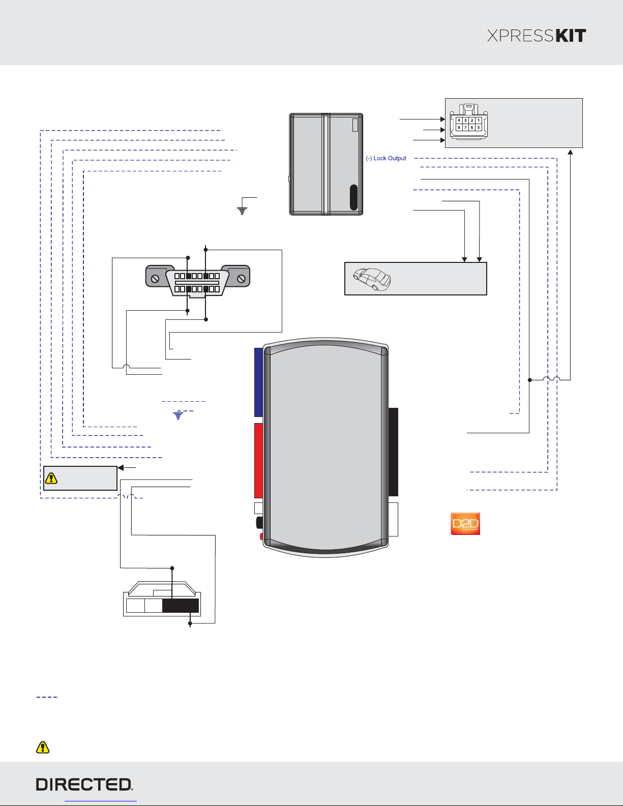
Installation Type 5
Rev.: 20170926
Page 14
See Reference
Chart for Door Lock
wire in vehicle.MUX
Diagnostic onnectorCOBDII
(connector side view)
MS CAN High: inP3
18
MS CAN Low: in 1P1
HS CA N High: 3Tan/Black:
MS CA N High: Orange/Green: 5
Ms CAN Low: Orange/Brown: 6
(+) 12V
(-) E-Brake Status Output: 1Black/White:
(-) Door Status Output: 3Green/White:
[]1 ( ) Tach Output: 5AC Violet/White:
(+) Brake Status Output: 6Gray:
( ) Door Lock Output: 9MUX Violet/Brown:
[]2 (-) Hood Status Output: 12Blue/Red:
HS CA N Low: 4Tan:
(-) Ground: 14Black:
TX: 10Yellow/Black:
RX: 11Orange/Black:
[]2 (-) Hood Status Input
(+) Brake Status Input
[]1 ( ) Tach InpuAC t
(-) Door Status Input
(-) E-Brake Status Input
(-) Ground
HS CAN High: inP6
169
HS CAN Low: in 1P4
14
(+) 12V: 13Red:
12
2
RF
Prog Button.
LED
Starter
Remote
DBALL2
(+) 12V Input
(+) Accessory Output
(+) Starter Output
(-) Unl Outputock
(+) Ignition Output
(-) (Status)GWR
( utput-) Trunk Release O [3]
(-) Parking Lights
Refer to the Vehicle Wiring
Reference Chart for wire
and connector details
10: (-) (Status) InputBlue/White: GWR
9: (+) Ignition InputPink:
10
2: (-) Unlock InputBlue:
1: (-) Lock InputGreen:
(+)12V
4
RX
(-) Ground
TX
P#: 2D65XKD
Ignition Connector
Refer to the Vehicle Wiring
Reference Chart for wire
and connector details.
TX: Pin 2
4 123
RX: Pin 1
Passive Anti-Theft
Security System (PATS)
connector
Not required in D2D mode.
[1] Tach wire is an optional connection required on some remote starters, which do not support a tach signal in D2D.
[2] Only if vehicle is equipped with OEM hood pin.
[]3 Trunk release output is ONLY required if trunk is not supported in data.
With the exception of the Diagnostic connector, all adapters are displayed from the wire side (unless specified otherwise).OBDII
© 2017 Directed. All rights reserved.
Page 15
Platform: DBALL2
Function Wire Color Pin Pola rity Location
Color Pins
Mazda 3 2004-2009
12V Red 4 (+) Ignition switch. White 8
Ignition Green/Yellow 1 (+) Ignition switch. White 8
Accessory Pink /Yellow 6 (+) Ignition switch. White 8
Starter Gray/Black 5 (+) Ignition s witc h. White 8
HS CAN High Gray/Violet 6 Data OBDII. Black 16
HS CAN Low Blue/White 14 Data OBDII. Black 16
MS CAN High Gray/Violet 3 Data OBDII. Black 16
MS CAN Low Blue/W hite 11 Data OBDII. Black 16
RX White/Green 1 Data Immobilizer Module around ignition switch. White 4
TX Gray/Orange 2 Data Immobilizer Module around ignition s witc h. White 4
Parking Light Blac k/White 1 (-) Headlight switch. W hite 12
Door Lock (W O/Alarm) Green/Red to Black/Blue N/A MUX Drivers kick panel. N/A N/A
Door Lock (W /Alarm) Black/Blue N/A MUX Drivers Kick panel. N/A N/A
Mazda 5 2006-2007
12V Black/Yellow 8 (+) Ignition switch. White 8
Ignition Blue 1 (+) Ignition s witc h. W hite 8
Accessory Black/Red 6 (+) Ignition switch. White 8
Starter Black/Blue 5 (+) Ignition switch. White 8
HS CAN High Red 6 Data OBDII. Black 16
HS CAN Low Blue 14 Data OBDII. Black 16
MS CAN High Blue/W hie 3 Data OBDII. Black 16
MS CAN Low Gray 11 Data OBDII. Black 16
RX Pink/Black 1 Data Immobilizer Module around ignition switch. White 4
TX Green 2 Data Immobilizer Module around ignition switch. W hite 4
Parking Light Brown/Red 1 (-) Headlight switch. White 12
Door Lock Blue N/A MUX Drivers k ick panel. N/A N/A
Mazda 5 2008-2010
12V Black/Yellow 8 (+) Ignition switch. White 8
Ignition Blue 1 (+) Ignition s witc h. W hite 8
Accessory Black/Red 6 (+) Ignition switch. White 8
Starter Black/Blue 5 (+) Ignition switch. White 8
HS CAN High Red 6 Data OBDII. Black 16
HS CAN Low White 14 Data OBDII. Black 16
MS CAN High Violet 3 Data OBDII. Black 16
MS CAN Low Gray 11 Data OBDII. Black 16
RX Pink/Black 1 Data Immobilizer Module around ignition switch. White 4
TX Green 2 Data Immobilizer Module around ignition switch. W hite 4
Parking Light Brown/Red 1 (-) Headlight switch. White 12
Door Lock Blue N/A MUX Drivers k ick panel. N/A N/A
Wire Information
Connector Information
Firmware: MA2
Rev.: 20170926
Type 5 - Vehicle Wiring Reference Chart
© 2017 Directed. All rights reserved.
Page 15
Page 16
Platform: DBALL2
Firmware: MA2
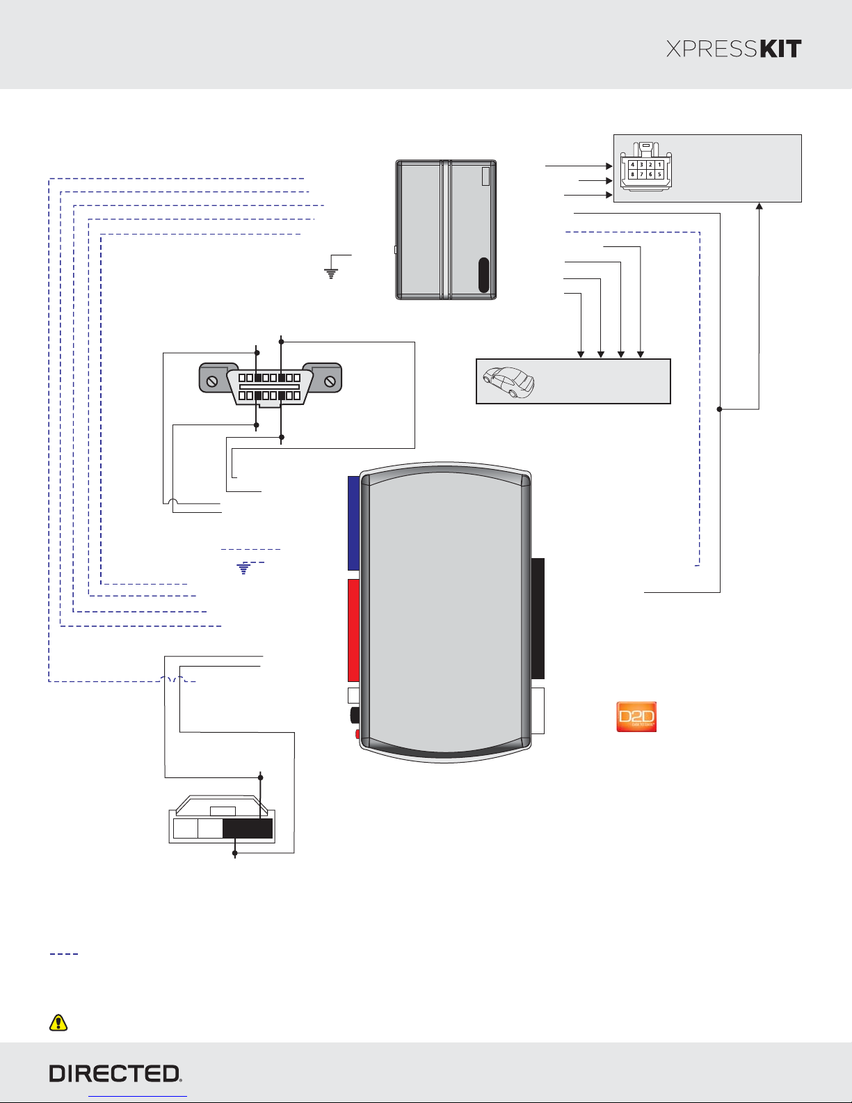
Installation Type 6
Diagnostic onnectorCOBDII
MS CA N High:
Gray/Orange, pin 3
MS CA N Low:
Violet/Orange, pin 11
[]2 (-) Hood Status Input
(+) Brake Status Input
[]1 ( ) Tach InpuAC t
(-) Door Status Input
(-) E-Brake Status Input
(connector side view)
HS CA N High: pin 6White/Blue,
18
169
HS CA N Low: in 1p4White,
(-) Ground
Starter
Remote
(+) 12V Input
(+) Accessory Output
(+) Starter Output
(+) Ignition Output
(-) (Status)GWR
(-) Trunk Release Output [3]
(+) Parking Lights
(-) OutputLock
(-) Unl Outputock
Refer to the Vehicle Wiring
Reference Chart for wire
and connector details
Rev.: 20170926
Page 16
Ignition Connector
Refer to the Vehicle Wiring
Reference Information for
wire and connector details.
HS CA N High: 3Tan/Black:
HS CA N Low: 4Tan:
MS CA N High: Orange/Green: 5
Ms CAN Low: Orange/Brown: 6
(+) 12V
(-) Ground: 14Black:
(-) E-Brake Status Output: 1Black/White:
(-) Door Status Output: 3Green/White:
[]1 ( ) Tach Output: 5AC Violet/White:
(+) Brake Status Output: 6Gray:
TX: 10Yellow/Black:
RX: 11Orange/Black:
[]2 (-) Hood Status Output: 12Blue/Red:
TX: pin 4Yellow/Orange,
1 432
RX: pin 3Violet/Gray,
Passive Anti-Theft
Security System (PATS)
connector
(+) 12V: 13Red:
14
12
2
RF
Prog Button.
LED
DBALL2
10: (-) (Status) InputBlue/White: GWR
9: (+) Ignition InputPink:
10
(+)12V
4
RX
(-) Ground
TX
P#: 2D65XKD
Not required in D2D mode.
[1] Tach wire is an optional connection required on some remote starters, which do not support a tach signal in D2D.
[2] Only if vehicle is equipped with OEM hood pin.
[]3 Trunk release output is ONLY required if trunk is not supported in data.
With the exception of the Diagnostic connector, all adapters are displayed from the wire side (unless specified otherwise).OBDII
© 2017 Directed. All rights reserved.
Page 17
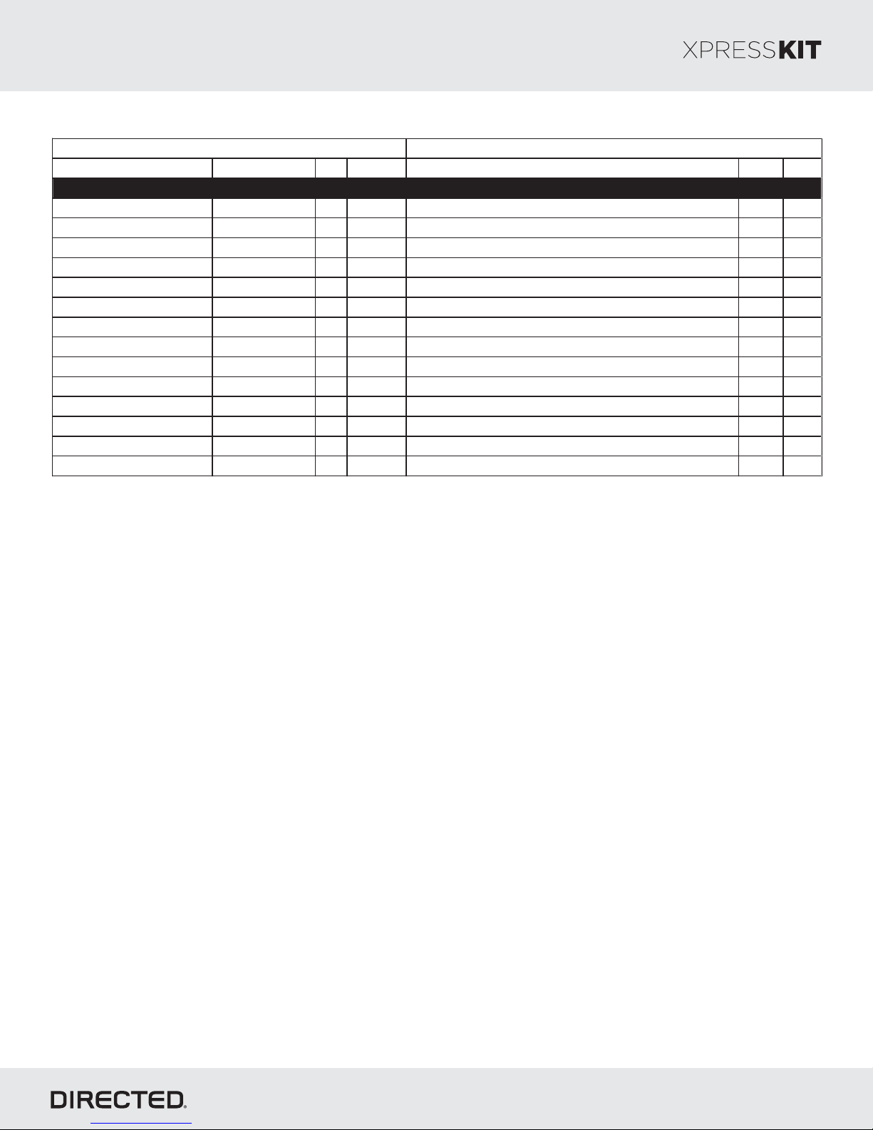
Platform: DBALL2
Function Wire Color Pin Polarity Location
Color Pins
Mazda Tribute 2008-2011
12V Blue/Red 4 (+) Ignition switc h. Blac k 7
Ignition W hite/Orange 1 (+) Ignition switch. Black 7
Accessory Violet/Green 6 (+) Ignition switch. Black 7
Starter Blue/White 7 (+) Ignition switch. Black 7
HS CAN High White/Blue 6 Dat a OBDII. Black 16
HS CAN Low W hite 14 Data OBDII. Black 16
MS CAN High Gray/Orange 3 Data OBDll Blac k 16
MS CAN Low Violet/Orange 11 Data OBDll Blac k 16
RX Violet/Gray 3 Data Immobilizer Module around ignition switch. Black 4
TX Yellow/Orange 4 Data Immobilizer Module around ignition s witch. Black 4
Parking Light Violet/White N/A (+) Driver kic k panel. N/A N/A
Door Lock Blue/Green 17 (-) Driver door harness. N/A N/A
Door unlock Yellow/Violet 4 (-) Driver door harness. N/A N/A
Rear liftgate Brown 7 (-) SJB (Smart Junction Box) right side of center c onsole. Gray 26
Wire Information
Connector Information
Firmware: MA2
Type 6 - Vehicle Wiring Reference Chart
Rev.: 20170926
Page 17
© 2017 Directed. All rights reserved.
Page 18
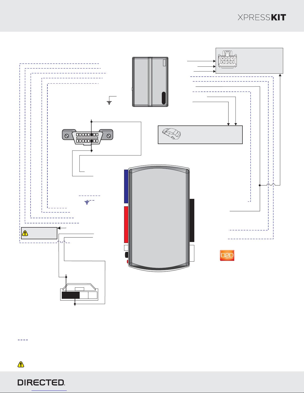
Platform: DBALL2
Firmware: MA2
Installation Type 7
Diagnostic onnectorCOBDII
(connector side view)
[]2 (-) Hood Status Input
(+) Brake Status Input
[]1 ( ) Tach InpuAC t
(-) Door Status Input
(-) E-Brake Status Input
(-) Ground
Starter
Remote
(+) 12V Input
(+) Accessory Output
(+) Starter Output
(-) OutputLock
(-) Unl Outputock
(+) Ignition Output
(-) (Status)GWR
( utput-) Trunk Release O [3]
(-) Parking Lights
Rev.: 20170926
Page 18
Ignition Connector
Refer to the Vehicle Wiring
Reference Chart for wire
and connector details.
See Reference
Chart for Door Lock
wire in vehicle.MUX
HS CAN High: inp6White,
18
169
HS CAN Low: in 1p4Black,
HS CA N High: 3Tan/Black:
HS CA N Low: 4Tan:
(+) 12V
(-) E-Brake Status Output: 1Black/White:
(-) Door Status Output: 3Green/White:
[]1 ( ) Tach Output: 5AC Violet/White:
(+) Brake Status Output: 6Gray:
( ) Door Lock Output: 9MUX Violet/Brown:
[]2 (-) Hood Status Output: 12Blue/Red:
(+) 12V: 13Red:
(-) Ground: 14Black:
TX: 10Yellow/Black:
RX: 11Orange/Black:
14
12
2
RF
Prog Button.
LED
DBALL/
Refer to the Vehicle Wiring
Reference Chart for wire
and connector details
10: (-) (Status) InputBlue/White: GWR
9: (+) Ignition InputPink:
10
2: (-) Unlock InputBlue:
1: (-) Lock InputGreen:
(+)12V
4
RX
(-) Ground
TX
2DBALL
P#: 2D65XKD
TX: pin 4Brown/Orange,
4 123
RX: pin 3Red/Black,
Passive Anti-Theft
Security System (PATS)
connector
Not required in D2D mode.
[1] Tach wire is an optional connection required on some remote starters, which do not support a tach signal in D2D.
[2] Only if vehicle is equipped with OEM hood pin.
[]3 Trunk release output is ONLY required if trunk is not supported in data.
With the exception of the Diagnostic connector, all adapters are displayed from the wire side (unless specified otherwise).OBDII
© 2017 Directed. All rights reserved.
Page 19
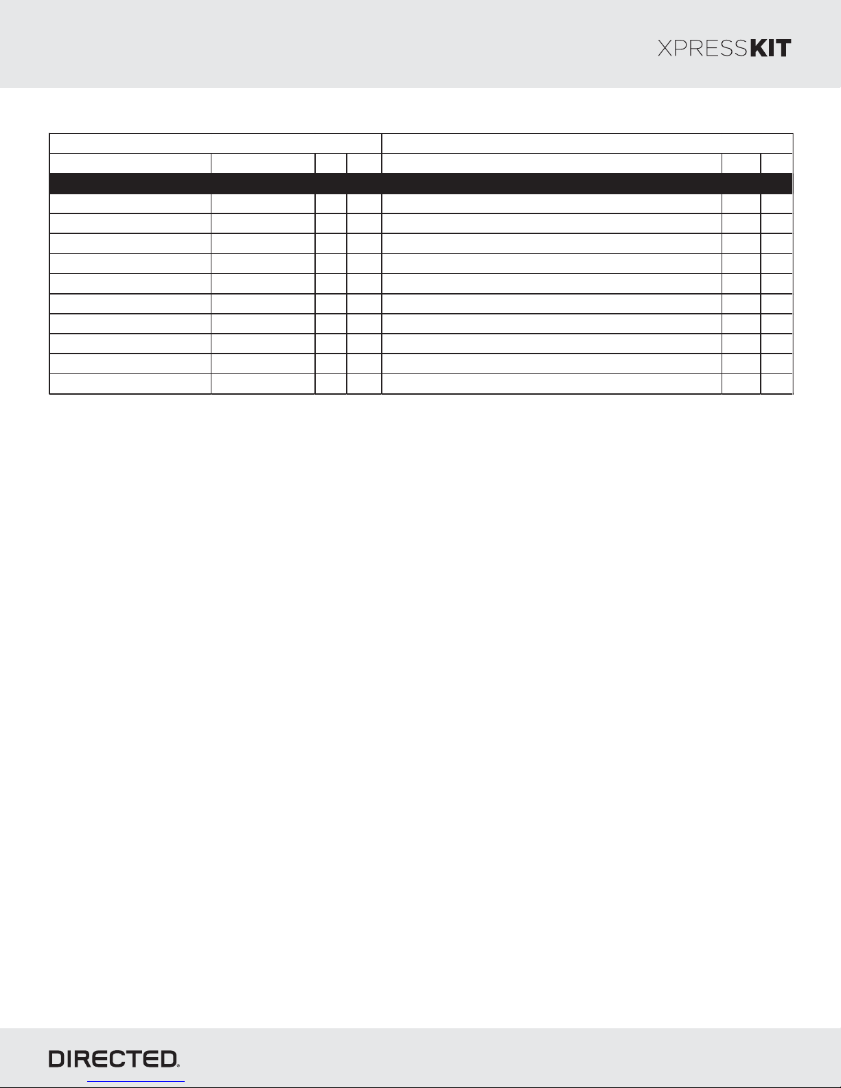
Platform: DBALL2
Function Wire Color Pin
Location
Color Pins
Mazda Tribute 2005-2007
12V Red 4 (+) Ignition s witch. Blac k 7
Ignition Lt. Green/Violet 1 (+)
Ignition switch. Black 7
Accessory Black/Lt. Green 6 (+) Ignition switch. Black 7
Starter Tan/Lt. Blue 7 (+) Ignition switch. Black 7
HS CAN High White 6 Data OBDII. Blac k 16
HS CAN Low Black 14 Data OBDII. Black 16
RX Red/Black 3 Data Immobilizer Module around ignition switch. Green 4
TX Brown/Orange 4 Data Immobilizer Module around ignition switch. Green 4
Parking Light Brown N/A (+) Driver kic k panel. N/A N/A
Door Lock/Unlock Pink/White MUX N/A Driver kic k panel. N/A N/A
Wire Informa tion
Connector Information
Firmware: MA2
Type 7 - Vehicle Wiring Reference Chart
Rev.: 20170926
Page 19
© 2017 Directed. All rights reserved.
Page 20
Platform: DBALL2
Firmware: MA2
Module Programming
Refer to the LED Diagnostics section on page for more information and for troubleshooting purposes.26
Important
Make all the required connections to the vehicle, as described in the wiring diagram(s) found in this guide, and double check to
ensure everything is correct prior to moving onto the next step.
Warning! To take advantage of advanced features, you must use Xpress 4.5 (and higher) or the Directechs Mobile app.VIP
Flashing a module using your computer:
1. Connect the interface module to your computer using the
XKLoader2.
2. Go to www.directechs.com using Internet Explorer, and
select the button.Flash Module
3. Follow the instructions to select your vehicle, installation
type, and configure your options.
4. Once you have configured the firmware options, click on the
FLASH button.
When the flashing operation is successful, you can proceed with the programming instructions below.
Flashing a module using your smartphone or tablet
1. Connect the interface module to your oader3.XKL
2. Launch the Directechs Mobile app on your smartphone or
tablet.
3. Select and follow the on screenFLASH YOUR MODULE
instructions.
Rev.: 20170926
Page 20
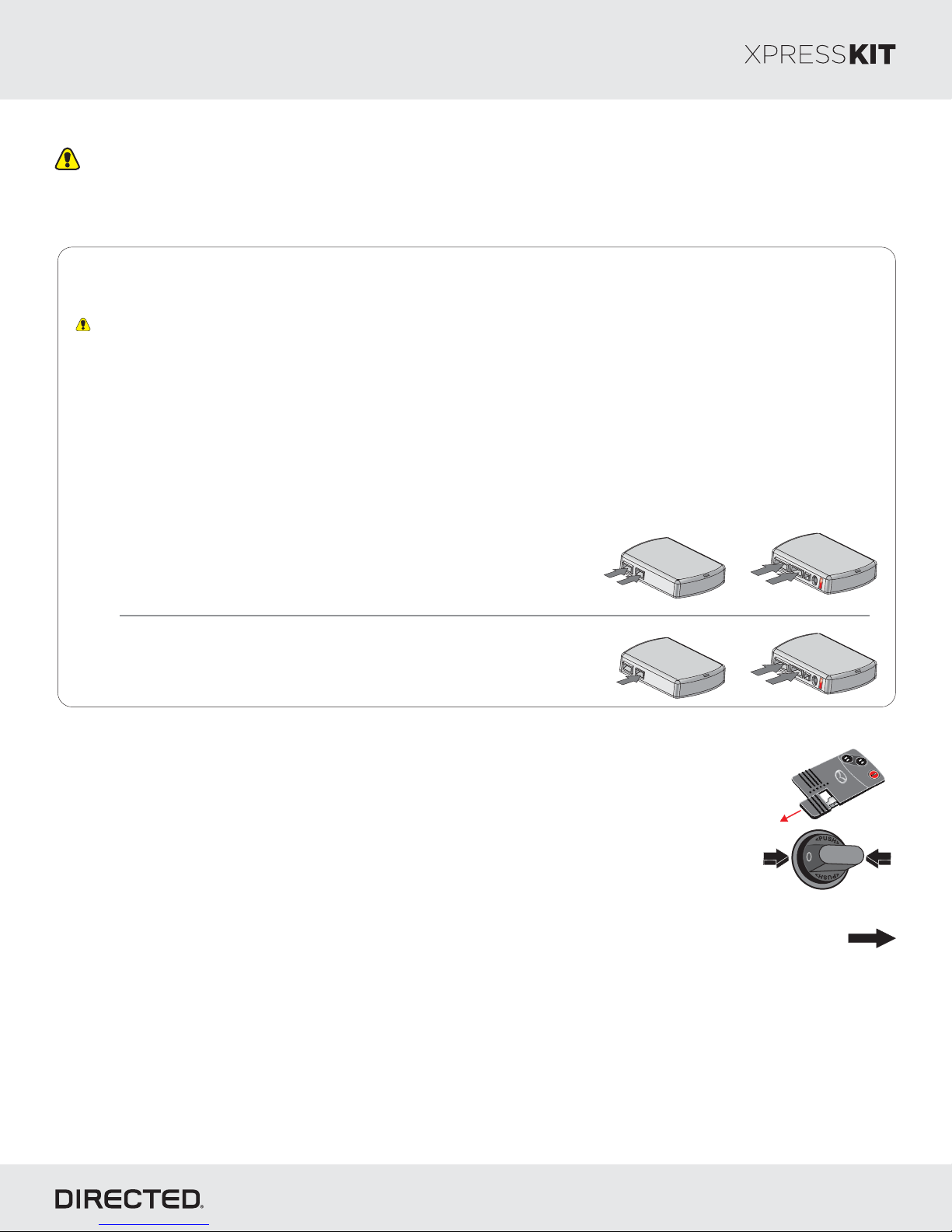
D2D Installation
If required for your installation, connect the 10-pin, 12-pin and 14-pin harnesses to
the module, then connect the 4-pin D2D harness.
D2D
10-pin
th
4
st
1
OR
W W Installation2
If required for your installation, connect the 10-pin and 12-pin harnesses to the
module, then connect the 14-pin harness to the module.
Note for Knob style vehicles:
Before starting the programming sequence, remove the metal key by sliding it out from the . TheOEM FOB
removal of the knob cover is necessary.
1- With the start knob in the position, remove the auxiliary key from the advanced key.OFF
2- Remove the cover of the start knob by pulling it outward while pressing both buttons on each side of the knob.
3- Proceed to module programming below.
Go to the next page t complete the module programming.o
D2D
10-pin
st
1
14-pin
12-pin
rd
3
nd
2
14-pin
12-pin
rd
3
nd
2
© 2017 Directed. All rights reserved.
Page 21
Platform: DBALL2
Firmware: MA2
Method 1 (using 1 key and Key2Go) - Recommended Method
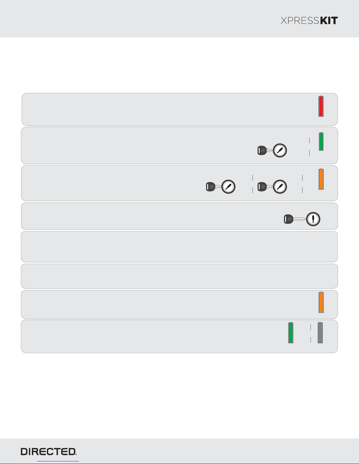
Wait until the LED turns solid red.ON
1
Note: Installations without HS CAN connections 5 times on the programming button,press
the LED turns ON solid Orange and proceed to step 2.
Rev.: 20170926
Page 21
Solid
Insert turnthe key into the ignition barrel and it to the position. TheON LED
2
flashes green.
Turn turnthe key to position then it to theOFF ON
3
position again. The flashes orange slowly.LED
Turn removethe key to and it from the ignition barrel.OFF
4
Remove the / 2 from the vehicle and reconnect it to your computer. The web siteDBALL DBALL Directechs
5
will automatically recognize that you are moving on to the second phase of the programming sequence.
Select the method and click on .Submit Key2 RequestGO
6
Once the configuration is completed, reconnect the / 2 to the vehicle.DBALL DBALL The flashes orange.LED
7
Key IN
OFF
ON
START
Key IN
Key IN
&
OFF
OFF
ON
START
ON
START
Key OUT
Key OUT
&
Flashes
Green
&
Flashes
Orange (slowly)
OFF
OFF
Flashes
ON
ON
START
START
The turns solid green, then turns once the module has been successfullyLED ON OFF
8
programmed.
You have successfully completed the programming sequence.module
&
Solid Green Off
© 2017 Directed. All rights reserved.
Page 22
Platform: DBALL2
Firmware: MA2
Method 2 (using 2 keys)
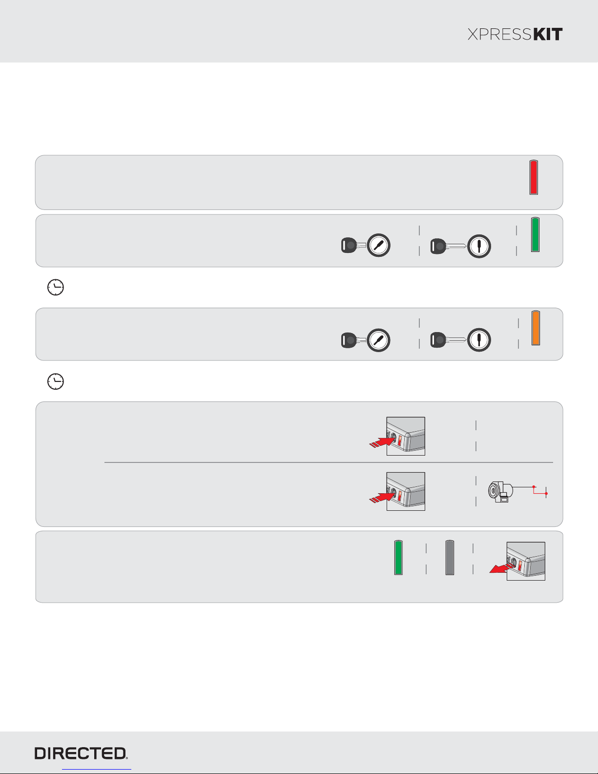
Important: Make sure all doors are closed on the vehicle before executing the programming sequence.
Wait until the LED turns solid red.ON
1
Note: Installations without HS CAN connections 5 times on the programming button,press
the LED turns ON solid Orange and proceed to step 2.
Rev.: 20170926
Page 22
Solid
Insert turnthe first key and it to the position, wait untilON
the security light turns , then it. TheOFF LEDremove
2
1st Valid
Key IN
OFF
ON
START
1st Valid
Key OUT
OFF
ON
START
flashes green.
Within seconds (if exceeded, restart programming at step 1, see page ):3 but no more than 10 seconds 12
&
2nd Valid
Key OUT
OFF
ON
START
Insert turnthe second key and it to the position, waitON
until the security light turns , then it.OFF remove
3
The flashes orange.LED
2nd Valid
Key IN
OFF
ON
START
Within seconds (if exceeded, restart programming at step 1, see page ):3 but no more than 10 seconds 12
Automatic Transmission:
the module programming button and then remote startPress & hold
the vehicule using the transmitter (keep holding the programming
button).
4
OR
Manual Transmission:
the module programming button and then applyPress & hold
(+)12 to the vehicle ignition wire with a jumper wire (keep holdingV
Press
and hold
button
Press
and hold
button
&
Remote Start
&
the programming button).
&&
Flashes
Green
&
Flashes
Orange
*
Ignition
Jumper wire
to +12V
+12V
The turns solid green for 3 seconds, then turnsLED ON OFF
once the module has been successfully programmed.
5
Release the programming button.
You have successfully completed the programming sequence.module
Solid
Green
&
&
OFF
© 2017 Directed. All rights reserved.
Release
Page 23
Platform: DBALL2
Firmware: MA2
Rev.: 20170926
Page 23
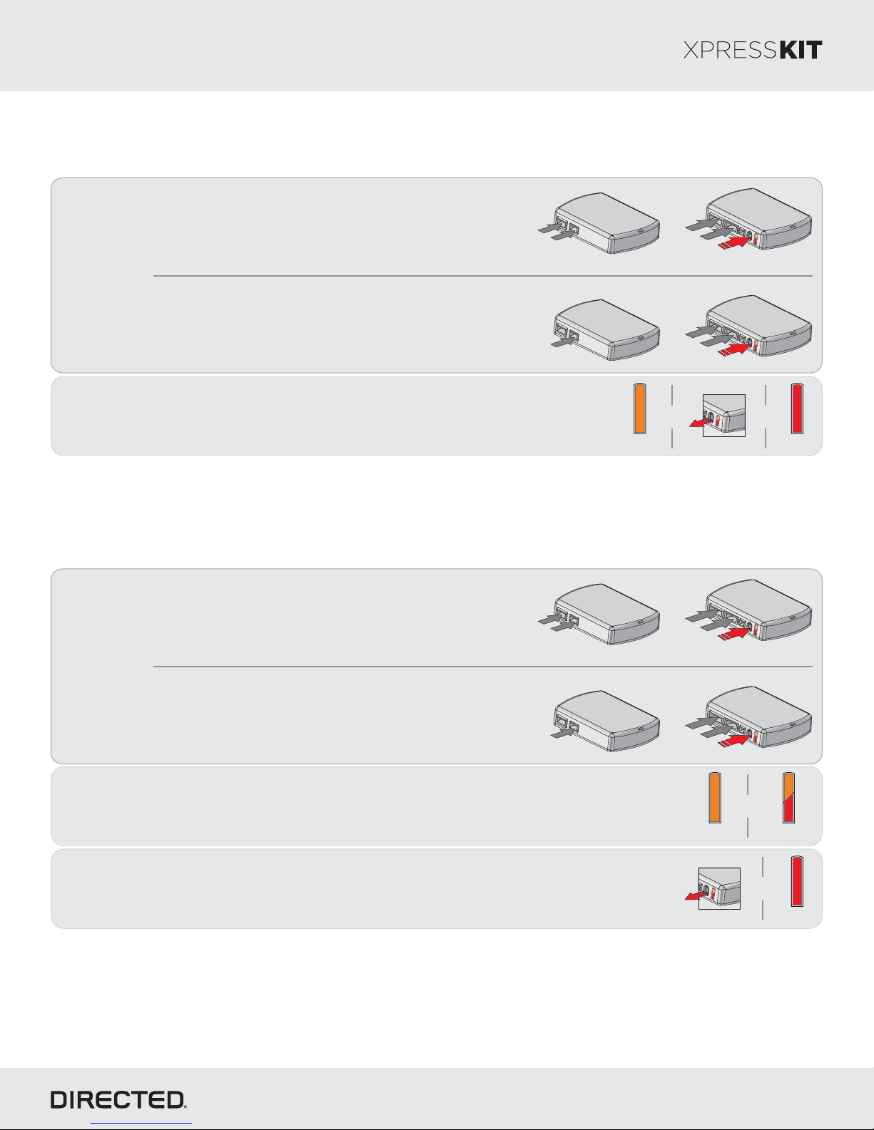
Module Reset
A module reset will only erase programming performed in the previous steps. All settings (firmware) and settings flashed
to the module using the web config tool will not be affected.
D2D Installation
If required for your installation, c , &onnect the 10-pin 12-pin
14-pin harnesses to the module Press hold the. and
p , then connect the 4-pin D2D harness.rogramming button
D2D
10-pin
th
5
st
1
rd
3
14-pin
12-pin
nd
2
th
4
OR
1
2
Hard Reset
Warning gainst xecuting a Hard Reset!AE
A hard reset will revert the flashed firmware back to its default settings. Depending on the installation, some settings (such
as and D2D options) may have to be reconfigured. See the section of this guide.RFTD Feature & Option List
W2W Installation
If required for your installation, connect the 10-pin & 12-pin
harnesses to the module Press hold the rogramming. and p
button, then connect the 14-pin harness to the module.
Wait 3 seconds until the orange then release theLED turns solidON
p The then turns solid red.rogramming button. LED ON
D2D Installation
If required for your installation, c , &onnect the 10-pin 12-pin
14-pin harnesses to the module Press hold the. and
p , then connect the 4-pin D2D harness.rogramming button
D2D
10-pin
st
1
th
4
14-pin
12-pin
nd
2
rd
3
& &
rd
3
Release
nd
2
4
14-pin
th
12-pin
Solid Solid
D2D
10-pin
th
5
st
1
1
2
3
OR
W2W Installation
If required for your installation, connect the 10-pin & 12-pin
harnesses to the module Press hold the rogramming. and p
button, then connect the 14-pin harness to the module.
Wait 3 seconds until the orange aitLED turns solid , and w 10 more secondsON
until the andLED starts to flash orange red.
Release the programming button. The turns solid red.LED ON
D2D
10-pin
st
1
th
4
14-pin
12-pin
nd
2
rd
3
&
Solid
Flashes
&
Release
Solid
© 2017 Directed. All rights reserved.
Page 24
Platform: DBALL2
Firmware: MA2
Web Programming (for Key2GO)
Refer to the LED Diagnostics section on page for more information and for troubleshooting purposes.26
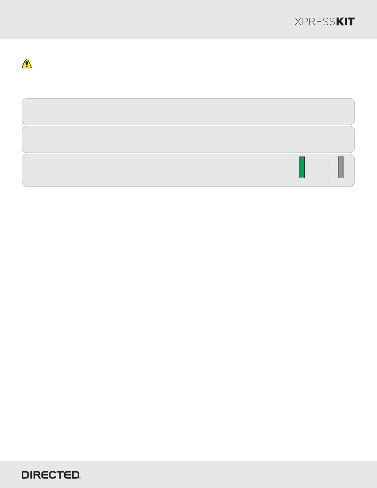
Version 4.5 or higher of XpressVIP must be installed on your computer to complete this programming sequence.
Remove the from the vehicle and reconnect it to your computer. The web site will automaticallymodule
1
recognize that you are moving onto the second phase of the programming sequence.
Rev.: 20170926
Page 24
2
3
You have successfully completed the programming sequence.module
Click on .Submit Key2G RequestO
Once the configuration is completed, reconnect the module.
The LED ON solid .turns green for 3 seconds, then turns off
Solid x3 Secs
&
Off
© 2017 Directed. All rights reserved.
Page 25
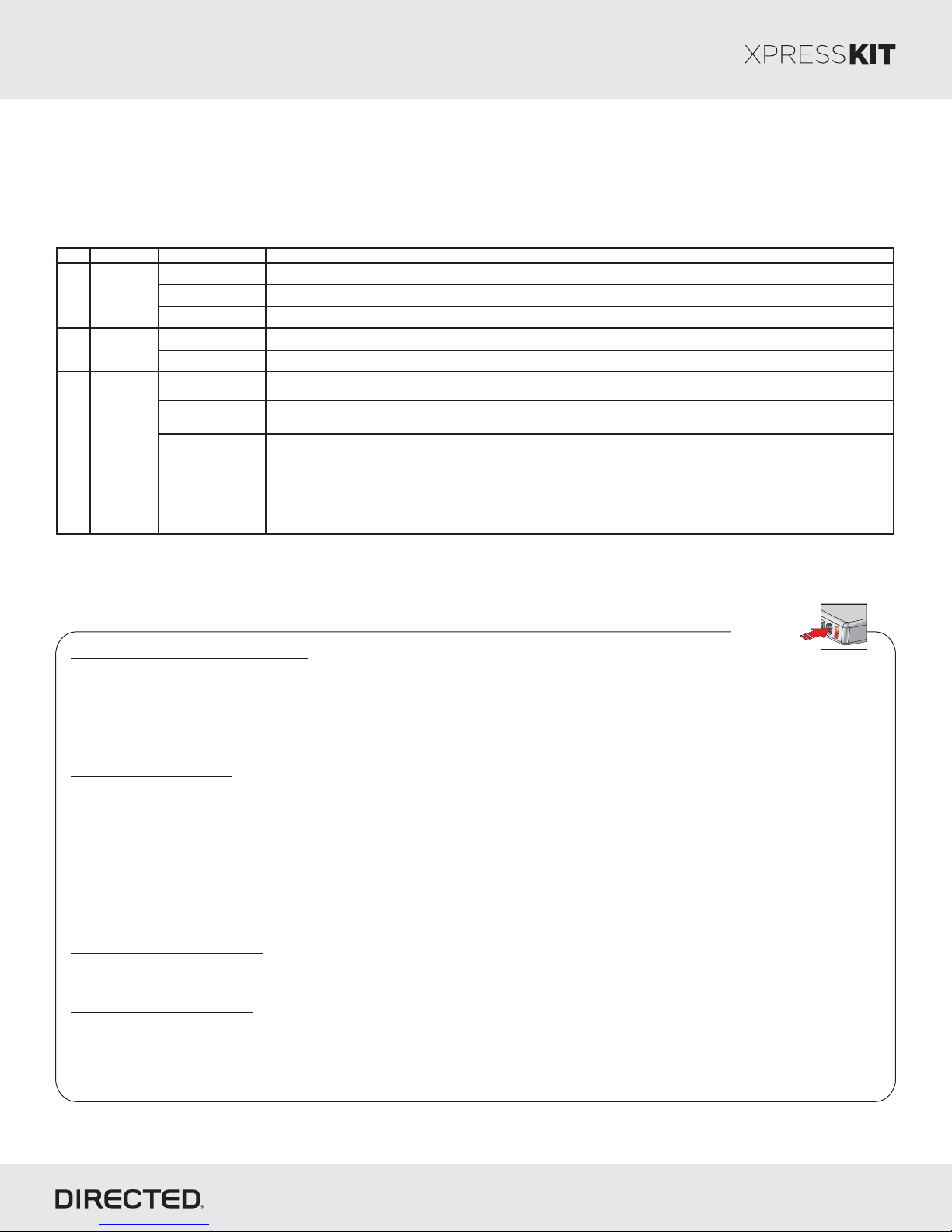
*Defaultoption
Feat. Operation Flashes / Option Description
1. Di sable d* Module is connected to a remot e st arter us ing a standard inst allation.
2. RFTD Output Module is connec ted to an XL202 using an RSR or RXT installation (when available).
3. S martStart Module is connec ted to SmartStart using an RSR or RXT installat ion (when available).
1. Driver Priority* Unlock s only the driver door on first press and unlock s all doors on a sec ond press within 5 sec onds.
2. A ll Unloc ks all doors on first press.
1. Disabled
The OEM alarm will not be c ontrolled by DBA LL upon remote start. No disarm or arm command will be ex ecuted at the
beginning or end of the sequenc e; it mus t be cont rolled by t he Remote Starter.
2. S afelock
Smart OEM Al arm Control will behave lik e a s tandard Safelock feature on a remote starter. It will unlock at t he beginning of the
sequence, and relock after start and shutdown.
3. Ena ble d*
Smart OEM Al arm Control will s ynchronize wit h the OEM alarm s o that it will dis arm and rearm t he vehicle in t he remote start
sequence, only when required. The reas on for thi s is, factory alarm control must often be done by lock or unloc k operation. This
could creat e unneces sary actions on door loc k modules, such as t he horn to honk. W hen possible, Smart OE M Alarm Control
will monit or the alarm and door lock status to detect if the disarm or rearm is required. If the vehicle is unlocked or is not
equipped wit h factory alarm, the disarm /rearm will not be executed. Smart OE M Alarm Control will als o monit or the remote
starter act ions so that t he factory alarm control is not done twic e. A remote starter, for whic h the Safeloc k feature is ac tive, will
work perfectly with this opt ion and will make it invisible to the user.
3
Smart
OEM
Alarm
Control
Unloc k
Driver
Priority
2
1
RF Output
Type
Platform: DBALL2
Firmware: MA2
Rev.: 20170926
Page 25
Feature Option List&
It is recommended to configure all features and options listed below thethe using configuration tool found on the module
flashing page on www.directechs.com. The web offers more options; however, manual configuration of the features is
possible using the information on this page.
Feature Programming
To enter feature programming routine
-
Turn t , thenhe ignition .ON OFF
-
Within 5 seconds, press and the rogramming button turns after 3 seconds . Release theHOLD LED ONp until the orange ( )
Programming button.
-
The to indicate the feature number is 1. After a short delay, the flashes rapidly to indicateLED LEDwill flash green once slowly red
the current option of feature 1 . repeat(i.e. 1x green followed by 1x red indicates feature 1 is set to option 1) The flashing sequence will
until .a new command is entered
Changing feature options
-
Press the arm or disarm button on aftermarket transmitter to change the option of the selected feature.lock/ unlock/
-
The flashes rapidly the number of times equal to the current option number. After a short delay, the flashes green slowlyLED LEDred
the number of times to indicate the current feature. repeat until .The flashing sequence will a new command is entered
Accessing another feature
-
Press and release the programming button a number of times to advance from the current feature to the next desired feature.
-
The flashes green slowly the number of times equal to the feature number. After a short delay, the flashes red rapidly toLED LED
indicate the current option of the current feature. repeat until .The flashing sequence will a new command is entered
When the maximum number of features or options is reached, the will start flashing again from the first feature or option.LED
Once a feature is programmed
-
Other features can be programmed.
-
The feature programming can be exited.
Exiting feature programming
-
No activity for 30 seconds; after 30 seconds, the will turn orange for 2 seconds to confirm the end of the programmingLED ON
sequence.
OR
-
Press and the programming button for 3 seconds. After 3 seconds, the will turn orange for 2 seconds to confirm theHOLD LED ON
end of the programming sequence.
Programming
Button
© 2017 Directed. All rights reserved.
Page 26
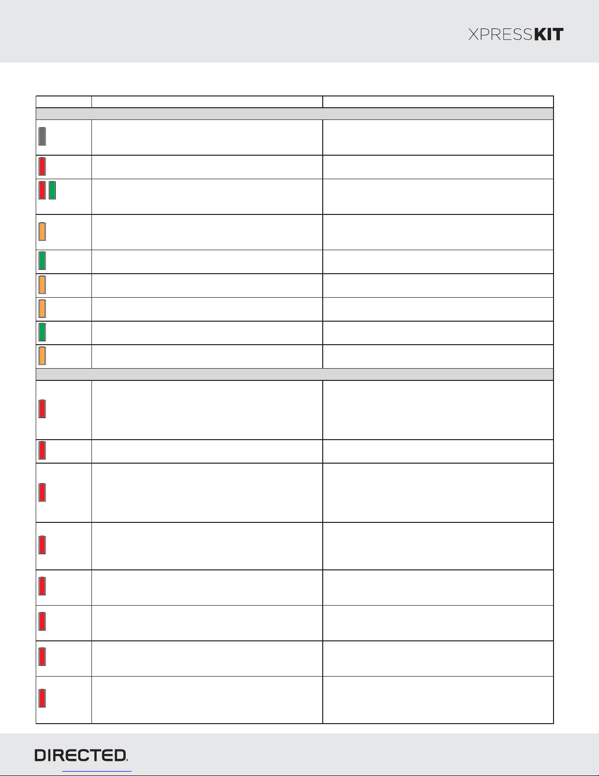
Platform: DBALL2
LED Description Troubleshooting
Module has no power.
Make sure the D2D harness is c onnected or that the 12
Volt is present between the red and black wires. If the
12 Volt is present, the module may be defective.
Waiting to begin the programming sequence.
Ensure the correct programming procedure is being
followed.
Initialization failed.
Reset the module and complete the programming again.
If the issue persists, pleas e contact Technical Support.
Transponder functions were skipped.
(If compatible) when RXT mode is not desired or
convenience features are needed, please reset and
reprogram the module.
All required CAN networks has been detected. Normal operation.
1 of 2 CAN networks has been detected. Normal operation
Key2GO initiated.
Pleas e follow the steps indicated in “Module
programming” to complete the Key2GO programming.
Module was s uccessfully programmed with all functions. Normal operation
Module was s uccessfully programmed without
transponder functions.
Normal operation.
CAN2 not detected.
Check the CAN2 Orange/Green and Orange/Brown wire
connections. Wake up the data bus by turning the
ignition on and try again. If your installation does not
require this connec tion, s kip this step by press ing the
programming button 5 times.
J1850 not detected.
Check the J1850 wire connection. Wake up the data bus
by turning the ignition on and try again.
CAN1 not detected.
Check the CAN1 Tan and Tan/Black wire connections .
Wake up the data bus by turning the ignition on and t ry
again. If your installation does not require this
connection, s kip this step by press ing the programming
button 5 t imes .
Bypass data not detected.
Check the bypass line connection. If more than one wire
is used, make s ure they are not inverted. Ens ure the
vehicle still operates correctly using the factory key.
Bypass processing error.
The bypass calc ulation failed. Reset the module and try
again. If the condition persists, please contact Technical
Support.
ISO 1 not detected.
The Yellow/Black wire did not detect the ex pect ed
signal. Refer to " Installation (wiring diagrams & vehicle
wiring reference charts)" to check the connections .
ISO 2 not detected.
The Orange/Black wire did not detect the expected
signal. Refer to " Installation (wiring diagrams & vehicle
wiring reference charts)" to check the connections .
MUX not detected.
The Violet/Green or Violet/Brown wire did not detect the
expected voltage value. Refer to "Installation (wiring
diagrams & vehicle wiring reference c harts)" to c heck
the connections.
Module Programming
Module Programming - Error Codes
Firmware: MA2
LED Diagnostics & Troubleshooting
Off
Solid red
Flashes red
& green
Solid orange
Flashes
green
Flashes
orange
Flashes
orange
slowly
Solid green
x 3 secs
Solid orange
x 3 secs
Rev.: 20170926
Page 26
Flashes red
x 1
Flashes red
x 1
Flashes red
x 2
Flashes red
x 3
Flashes red
x 4
Flashes red
x 5
Flashes red
x 6
Flashes red
x 7
© 2017 Directed. All rights reserved.
Page 27
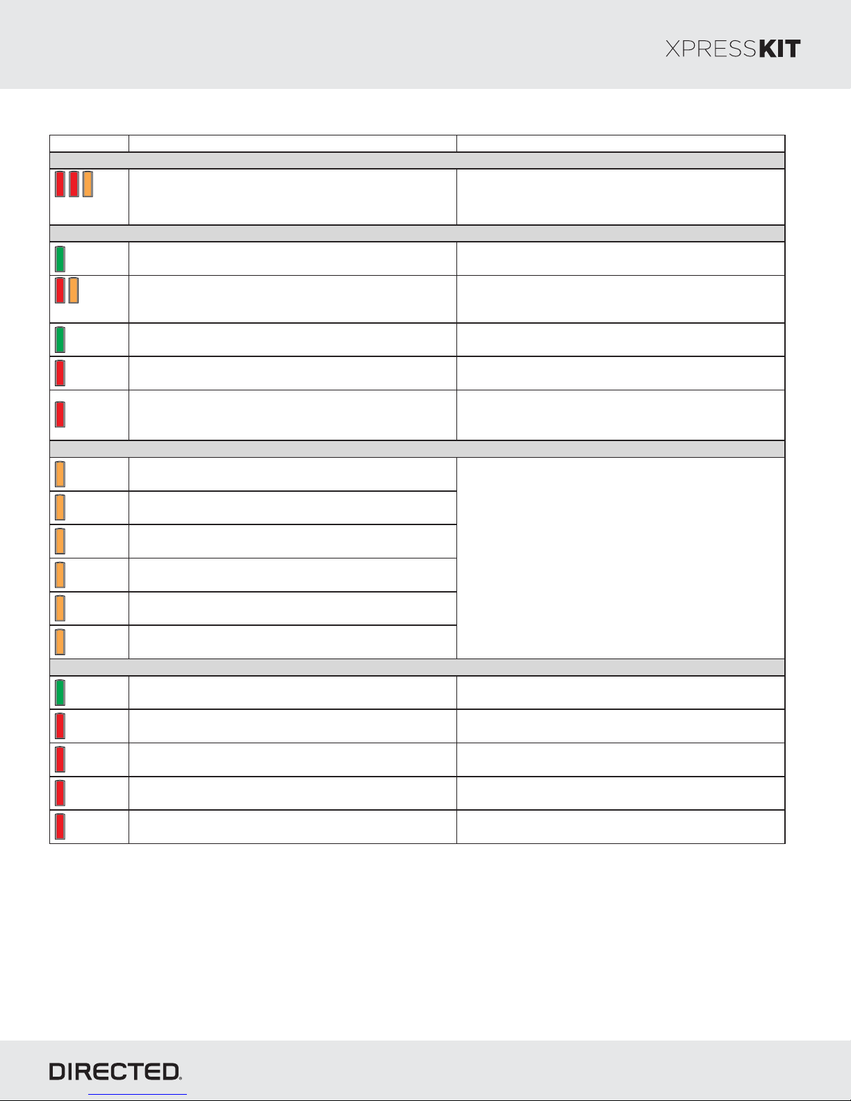
Platform: DBALL2
LED Description Troubleshooting
OBDII feature is not s upported.
The diagnostic data bus was not detected, therefore the
SmartStart features will be limited.
Ground W hen Running (Status) command rec eived. The module has initialized the remote start sequenc e.
Ignition ON command received.
The module has received the Ignition ON command and
is proces sing the remote start sequence.
Start ON command received.
The module has received the Start ON c ommand and is
processing the remote start s equence.
PTS s hutdown error.
The PTS out put from the module was not ac tivated due
to safety protection.
CAN bus incorrectly detec ted.
Verify the CAN1 and CAN2 connections. Refer to
“Installation (wiring diagrams & vehicle wiring reference
charts)” to check the connections.
LOCK command received.
UNLOCK c ommand received.
TRUNK c ommand received.
AUX1 command received.
AUX2 command received.
AUX3 command received.
Takeover successful. Normal operation.
Runsafe was not disabled.
No UNLOCK command was received prior to opening the
door, or the 45 second timer expired in takeover mode.
Brake was not detected.
The brakes were not detected, which prevents the
system from shutting down the vehicle.
Smart key was not detected.
The smart key was not detected, which prevents the
system from shutting down the vehicle.
Speed was detected.
The vehicle was detected as moving, which prevents the
system from shutting it down.
External module synchronization
Commands
Activation Ground When Running (Status)
If the bypass module fails to flash, it did not receive the
signal. Commands can come from RF or D2D.
Shutdown codes
Firmware: MA2
LED Diagnostics & Troubleshooting
(Flashes red,
red then
orange) x 10
Flashes
green
Flashes red
& orange
Flashes
green
quickly
Flashes red
x 10
Flashes red
x 21
Rev.: 20170926
Page 27
Flashes
orange x 1
Flashes
orange x 2
Flashes
orange x 3
Flashes
orange x 4
Flashes
orange x 5
Flashes
orange x 6
Flashes
green x 1
Flashes red
x 1
Flashes red
x 2
Flashes red
x 3
Flashes red
x 4
© 2017 Directed. All rights reserved.
Page 28
Platform: DBALL2
Firmware: MA2
Rev.: 20170926
Page 28
Limited Consumer WarrantyOne Year
For a period of from the date of purchase of a Directed Electronics remote start or security product, DirectedONE YEAR
Electronics. (“ ”) promises to the original purchaser, to repair or replace with acomparable reconditioned piece, theDIRECTED
security or remote start accessory piece (hereinafter the “Part”), which proves to be defective in workmanship or material
under normal use, provided the following conditions are met: the Part was purchased from an authorized dealer;DIRECTED
and the Part is returned to , postage prepaid, along with a clear, legible copy of the receipt or bill of sale bearing theDIRECTED
following information: consumer’s name, address, telephone number, the authorized licensed dealer’s name and complete
product and Part description.
This warranty is nontransferable and is automatically void if the Part has been modified or used in a manner contrary to its
intended purpose or the Part has been damaged by accident, unreasonable use, neglect, improper service, installation or
other causes not arising out of defect in materials or construction.
TO THE MAXIMUM EXTENT ALLOWED BY LAW EXCEPT AS STATED ABOVE ALL WARRANTIES INCLUDING,,,
BUT NOT LIMITED TO EXPRESS WARRANTY IMPLIED WARRANTY WARRANTY OF MERCHANTABILITY,, ,
FITNESS FOR PARTICULAR PURPOSE AND WARRANTY OF NONINFRINGEMENT OF INTELLECTUAL
PROPERTY ARE EXPRESSLY EXCLUDED AND DIRECTED NEITHER ASSUMES NOR AUTHORIZES ANY,;
PERSON OR ENTITY TO ASSUME FOR IT ANY DUTY OBLIGATION OR LIABILITY IN CONNECTION WITH ITS,
PRODUCTS DIRECTED HEREBY DISCLAIMS AND HASABSOLUTELYNO LIABILITY FOR ANY AND ALL ACTS OF.
THIRD PARTIES INCLUDING DEALERS OR INSTALLERS DIRECTED IS NOT OFFERING GUARANTEE OR.A
INSURANCE AGAINST VANDALISM DAMAGE OR THEFT OF THE AUTOMOBILE ITS PARTS OR CONTENTS,, , ,
AND DIRECTED HEREBY DISCLAIMS ANY LIABILITY WHATSOEVER INCLUDING WITHOUT LIMITATION,,
LIABILITY FOR THEFT DAMAGE OR VANDALISM IN THE EVENT OF CLAIM OR DISPUTE INVOLVING,, . A A
DIRECTED OR ITS SUBSIDIARY THE PROPER VENUE SHALL BE SAN DIEGO COUNTY IN THE STATE OF,
CALIFORNIA CALIFORNIA STATE LAWS AND APPLICABLE FEDERAL LAWS SHALL APPLY AND GOVERN THE.
DISPUTE THE MAXIMUM RECOVERY UNDER ANY CLAIM AGAINST DIRECTED SHALL BE STRICTLY LIMITED.
TO THE AUTHORIZED DIRECTED DEALER PURCHASE PRICE OF THE PART DIRECTED SHALL NOT BE’S .
RESPONSIBLE FOR ANY DAMAGES WHATSOEVER INCLUDING BUT NOT LIMITED TO ANY CONSEQUENTIAL,,
DAMAGES INCIDENTAL DAMAGES DAMAGES FOR THE LOSS OF TIME LOSS OF EARNINGS COMMERCIAL,, ,,
LOSS LOSS OF ECONOMIC OPPORTUNITY AND THE LIKE NOTWITHSTANDING THE ABOVE THE,.,
MANUFACTURER DOES OFFER LIMITED WARRANTY TO REPLACE OR REPAIR AT DIRECTED OPTION THEA’S
PARTAS DESCRIBED ABOVE.
This warranty only covers Parts sold within the UnitedStates of America and Canada. Partssold outside of the United States of
America or Canada are sold “ - ” and shallhave , express or implied.Some states do not allow limitationsAS IS NO WARRANTY
on how long an implied warranty will last or the exclusion or limitation of incidental or consequential damages. This warranty
gives you specific legal rights and you may also have other rights that vary from State to State. does not and hasDIRECTED
not authorized any person or entity to create for it any other obligation, promise, duty or obligation in connection with this Part.
For further details relating to warranty information of Directed products, please visit the support section of ’sDIRECTED
website at: www.directed.com
920-10012-01 2013-07
This Interface kit / Data Bus Interface part has been tested on the listed vehicles. Other vehicles will be added to the select
vehicle list upon completion of compatibility testing.Visit website for latest vehicleapplication guide. : Under noDISCLAIMER
circumstances shall the manufacturer or the distributors of the bypass kit / data bus interface part(s) be held liable for any
consequential damages sustained in connection with the part(s) installation.The manufacturer and it’s distributors will not, nor
will they authorize any representative or any other individual to assume obligation or liability in relation to the interface kit / data
bus interface part(s) other than its replacement. N.B.: Under no circumstances shall the manufacturer and distributors of this
product be liable for consequential damages sustained in connection with this product and neither assumes nor authorizes
any representative or other person to assume for it any obligation or liability other than the replacement of this product only.
Protected by U.S. Patents: 5,719,551; 6,011,460 B1 *; 6,243,004 B1; 6,249,216 B1; 6,275,147 B1; 6,297,731 B1; 6,346,876
B1; 6,392,534 B1; 6,529,124 B2; 6,696,927 B2; 6,756,885 B1; 6,756,886 B2; 6,771,167 B1; 6,812,829 B1; 6,924,750 B1;
7,010,402 B1; 7,015,830 B1; 7,031,826 B1; 7,046,126 B1; 7,061,137 B1; 7,068,153 B1; 7,205,679 B1; Cdn. Patent:
2,320,248; 2,414,991; 2,415,011; 2,415,023; 2,415,027; 2,415,038; 2,415,041; 2,420,947; 2,426,670; 2,454,089; European
Patent: 1,053,128; Pat. Pending: 2,291,306. Made in Canada.
© 2017 Directed. All rights reserved.
Page 29
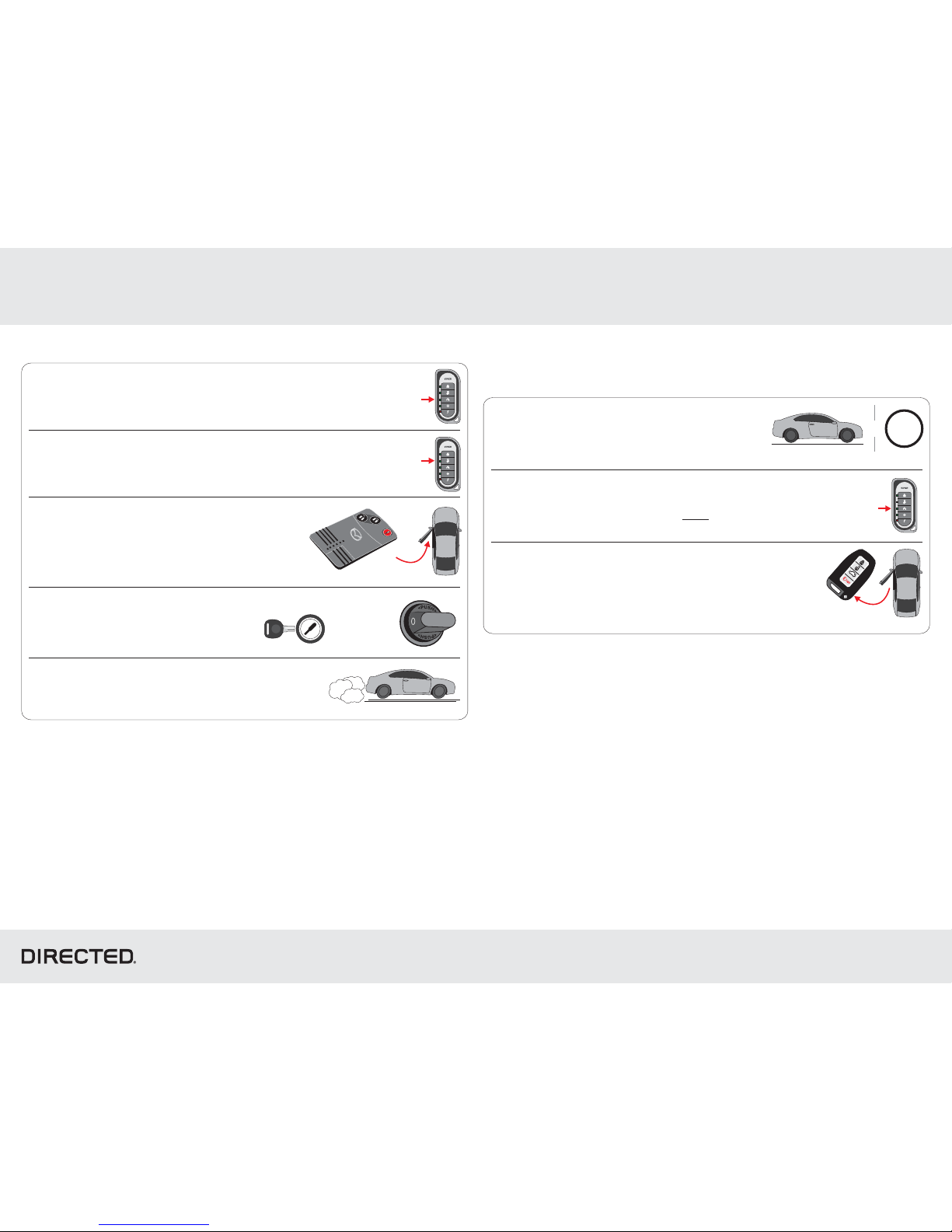
Quick Reference Guide
© 2017 Directed. All rights reserved.
Vehicle Takeover
4
5
3
1
1
2
3
Stop the vehicle in a safe parking spot
and put the gear in Park (P).
2
Ready to
drive off
Press
remote start
*button
Press
remote start
*button
Press Unlock
onbutton
either remote*
* Your aftermarket remote may differ from the model shown in the illustrations.
* Your aftermarket remote may differ from the model shown in the illustrations.
Stop & put vehicle in Park (P)
P
&
HOLD
E vehicle withxit
Smart Key
Enter vehicle
Pit Stop Mode
The Mode feature is practical when you need to stop and run an errand,Pit Stop
but wish to keep the engine running.
DBALL2-MA2
Close sendthe vehicle doors, hood and trunk, then
the Remote Start command to start the vehicle*.
Send the Unlock command on the factory or
aftermarket remote*.
Key IN
OFF
START
ON
OR
Enter the vehicle, while making sure the
factory remote is inside with you.
Press the button to remote start the vehicle.*
The Parking Lights will flash to indicate theonce
vehicle is now in P Modeit Stop .
Turn the ignition ON.
Depress putthe brake pedal, the
car in gear and drive off.
It is now safe to leave the exitengine running and
the vehicle with the in hand.factory remote
Note: We recommend that you always lock the
doors of your vehicle when leaving it unattended.
Page 30
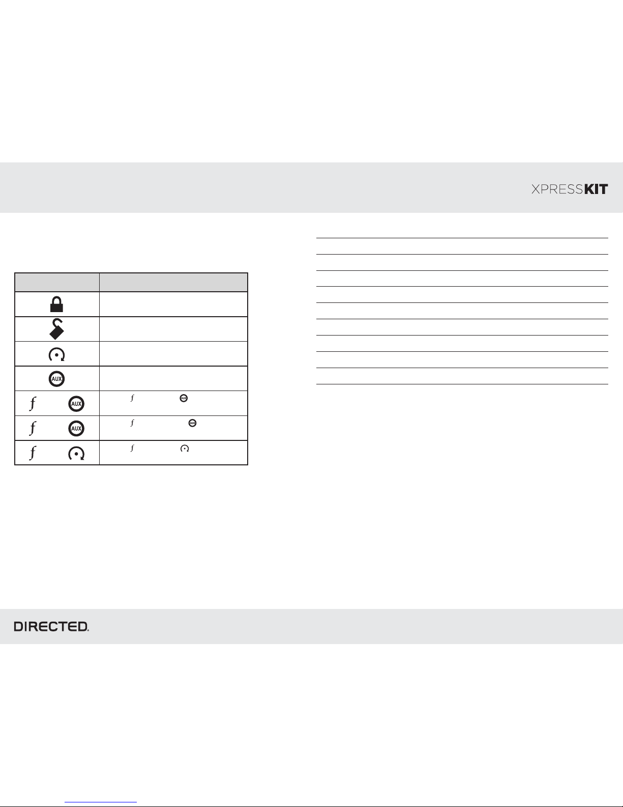
Quick Reference Guide
© 2017 Directed. All rights reserved.
Button(s)
Actions
Press & hold for 1 s econd to loc k.
Press & hold for 1 s econd to unloc k.
Press & hold for 1 s econd to remot e
start.
Press & hold for 5 s econds t o activate
the trunk release (opt ional).
Press once, then to ac tivate the
rear hatc h/tail glas s release (optional).*
Press 3 times, t hen to ac tivate
the panic mode.
Press once, then to reset t he
remote starter runtime.
List of Available Commands
x1 +
x3 +
x1 +
* This output is configurable. see your authorized installation center for more
information.
Note that the information below is for Viper, Clifford and Python models. Icons and
commands may differ depending on the remote brand and model purchased. Refer
to your authorized installation center for more information.
Notes
DBALL2 MA2-
 Loading...