

Page 1
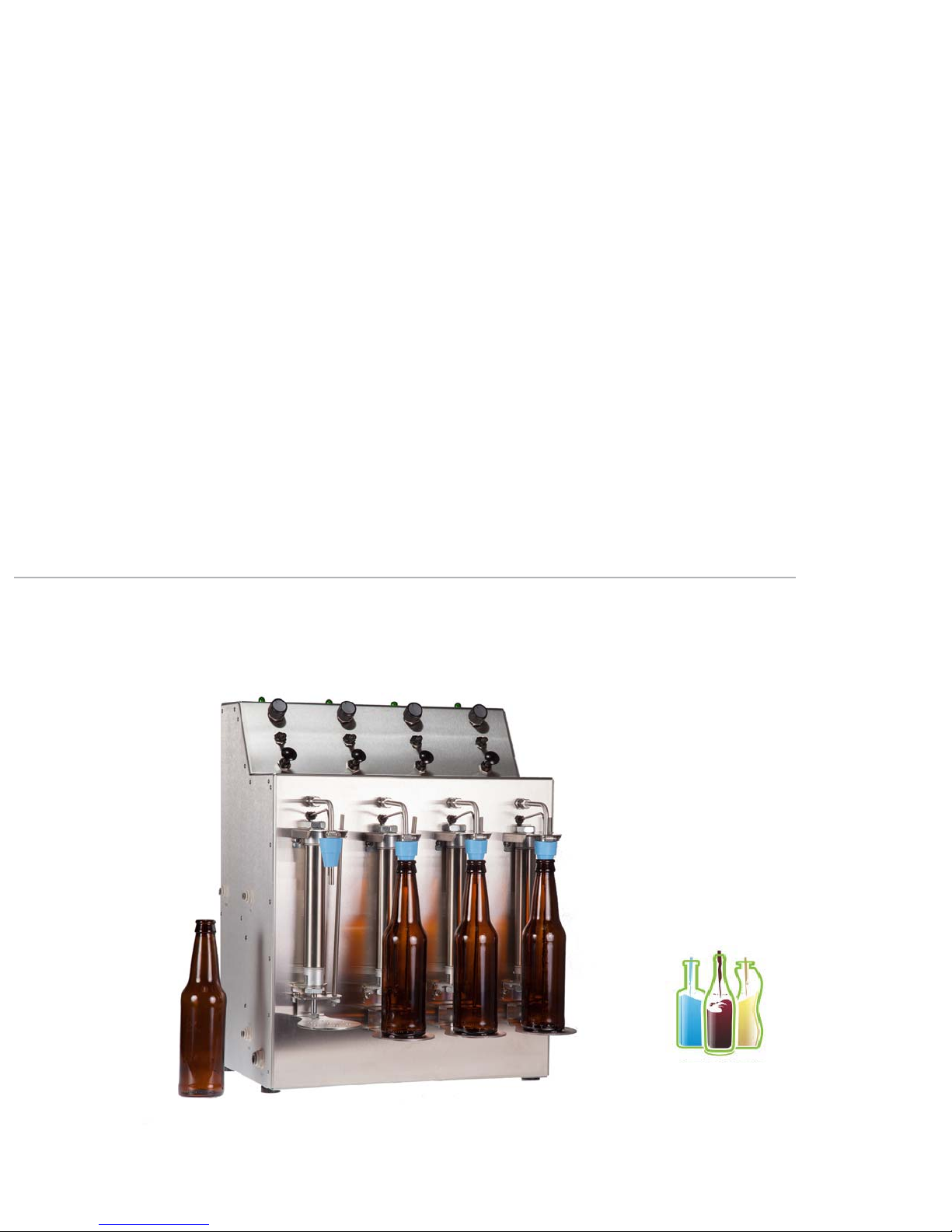
XpressFill XF4500 Counter Pressure Filler
Operating Instructions
Page 2

ii | XPRESSFILL Systems LLC
ank you for choosing our handcrafted bottle fi ller as the technology to bottle your passion. We
look forward to assisting you in experiencing the best performance from your fi ller.
is manual is written with your safety and convenience in mind. We highly recommend reading
the manual before using your fi ller for the fi rst time.
If you have any questions or comments, please do not hesitate to contact us.
lling machine.
XpressFill Systems LLC
265 Prado Road, Suite #1
San Luis Obispo, CA 93401
USA
(805) 541-0100
ll.com
ll.com
Important Safety Instructions
Misuse of the bottle-fi lling machine can result in serious injury or death. Do not use the machine
in any way not covered in this manual or for any purpose other than those explained in the
following pages.
Severe product damage and/or injury could result from the use of unqualifi ed Service
Technicians or non-original replacement parts. All repairs must be performed by a qualifi ed
Service Technician or with the approval from an XpressFill Technician. Only original factory
replacement parts should be used.
Electrical shock or fi re could result if the electrical supply for the bottle fi ller covered in this
manual is not correctly installed or if the bottle fi ller has been improperly grounded. Do not
use the bottle fi ller covered in this manual unless you are certain the electrical supply has been
correctly installed and the bottle fi ller has been properly grounded.
265 Prado Road, Suite 1 • San Luis Obispo, CA 93401 • Tel: (805) 541-0100 • sales@xpressll.com
Page 3
iii XPRESSFILL Systems LLC
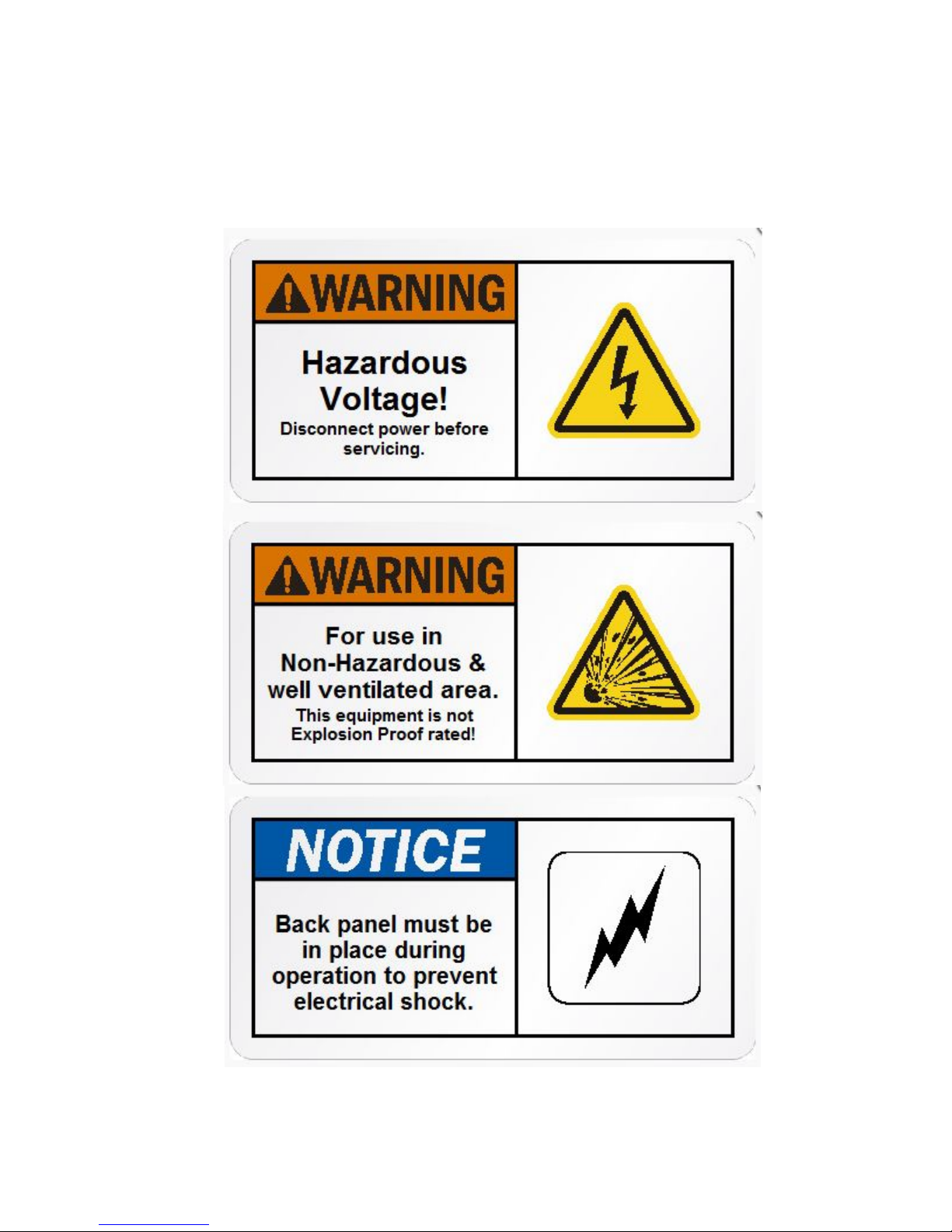
Safety Warnings
Page 4
XPRESSFILL Systems LLC | 1
Table of Contents
iii Safety Warnings
1 1 noitcudortnI
2 2 relliF ruoY wonK
3 4 relliF ruoY pU teS
4 5 serudecorP gnitarepO
5 8 gnitoohS elbuorT
6 9 r
elliF ruoY gninaelC
Introduction
1
XpressFill Product Guarantee
e fi ller will
be repaired or replaced if, upon inspection at the factory, the fi ller is found to be defective in
materials or workmanship.
is guarantee does not apply to damage resulting from normal wear and tear, accident, abuse,
e guarantee will be rendered invalid if the customer has made repairs or
alteration to the machine without fi rst consulting XpressFill Systems LLC.
265 Prado Road, Suite 1 • San Luis Obispo, CA 93401 • Tel: (805) 541-0100 • sales@xpressll.com
Page 5
2 | XPRESSFILL Systems LLC
Know Your Filler
2
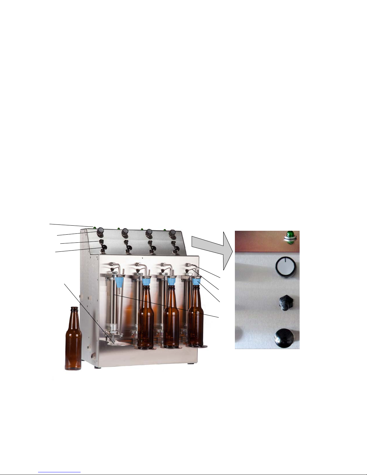
The below diagram highlights the important features on your fi ller, which will be referenced
throughout this manual. Being familiar with each of these and their functions will make your
fi lling experience easier.
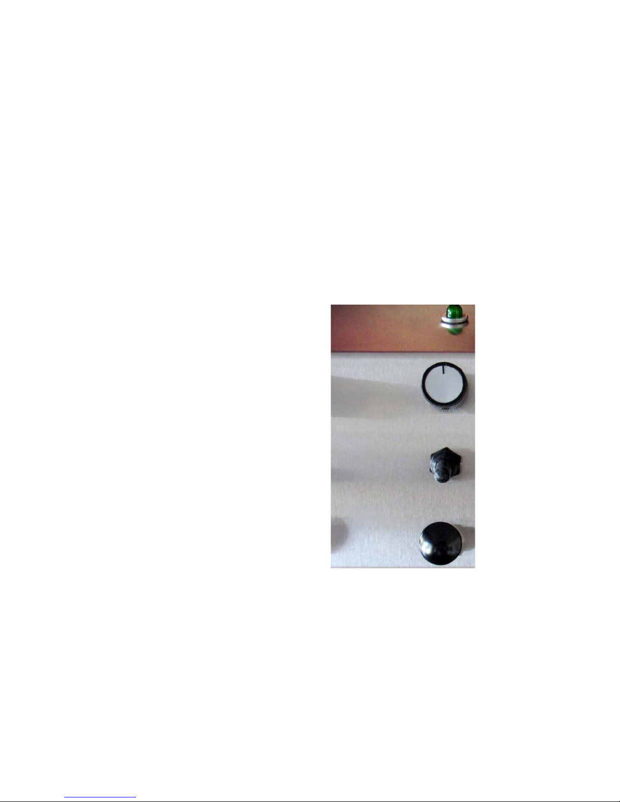
Bottle fi ll indicator light1.
Bottle pressure adjustment (30 turn knob)2.
Fill toggle switch (3 position)3.
a. Start ll
b. Stop ll
c. Bottle release
1.
Pressure release knob
4.
Bottle rest foot
5.
Upper spout / product filling
6.
7. Lower spout / pressurizing & release
8. Bottle neck filling stopper
9. Pneumatic ram
2.
3.
4.
Bottle Pressure
Adjustment
6.
5.
7.
8.
Start Fill
Stop Fill
Bottle Release
9.
Pressure Release
265 Prado Road, Suite 1 • San Luis Obispo, CA 93401 • Tel: (805) 541-0100 • sales@xpressll.com
1.Bottle ll
indicator light
2. Bottle pressure
adjustment knob
3. Fill toggle
switch
4. Pressure release
knob
Page 6

XPRESSFILL Systems LLC | 3
1. Fill Indicator Light is green light will
turn on while the liquid is fl owing from the
spout.
2. Bottle Pressure Adjustment Knob -
Pressure release knob (30 turn) that allows
you to adjust the pressure inside the bottle.
Turning the knob counterclockwise will
lower the pressure inside the bottle, while
turning it clockwise will increase the pressure.
is will typically only need to be adjusted
when setting up your ller for the rst time
with a new liquid.
3. Fill Toggle Switch (3 position) -
is switch starts the ll in the full up
position, stops the ll in the middle
position, and releases the pneumatic ram
holding the bottle in place in the bottom
position.
Start Fill: Full Up
Stop Fill: Middle
Release Bottle: Full Down
5. Bottle Foot Rest
ese feet will hold your
bottle securely in place once the fi ll sequence is
started. Do not put your hands between the
bottle and the foot to prevent injury.
6. Upper Spout
is spout is used for the gas
fl ush and fi lling.
7. Lower Spout -
is spout is vented to
relieve the pressure in your bottle and acts as
the sensor for the automatic level fi lling system.
8. Stopper
e stopper seals your bottle and
helps to control the level your bottles is fi lled
to. While the stoppers are already set for the
level of a typical 12 oz. beer bottle, they can be
adjusted up and down on the spout to fi ll to
your own specifi cations.
9. Pneumatic Ram
e pneumatic ram
lifts the bottle foot rest and is activated when
the lling sequence begins.
4. Pressure Release Knob -
is is a push / pull knob to manually
control a valve to release the pressure in the
bottle. is knob should be pushed in prior
to starting the ll sequence so the bottle
will pressurize. Once the ll is complete, set
the Fill Toggle Switch to the “Stop Fill”
position and pull the Pressure Release Knob
to release the pressure in the bottle.
265 Prado Road, Suite 1 • San Luis Obispo, CA 93401 • Tel: (805) 541-0100 • sales@xpressll.com
Page 7
XPRESSFILL Systems LLC | 4
Setting Up Your Filler and Filling
3
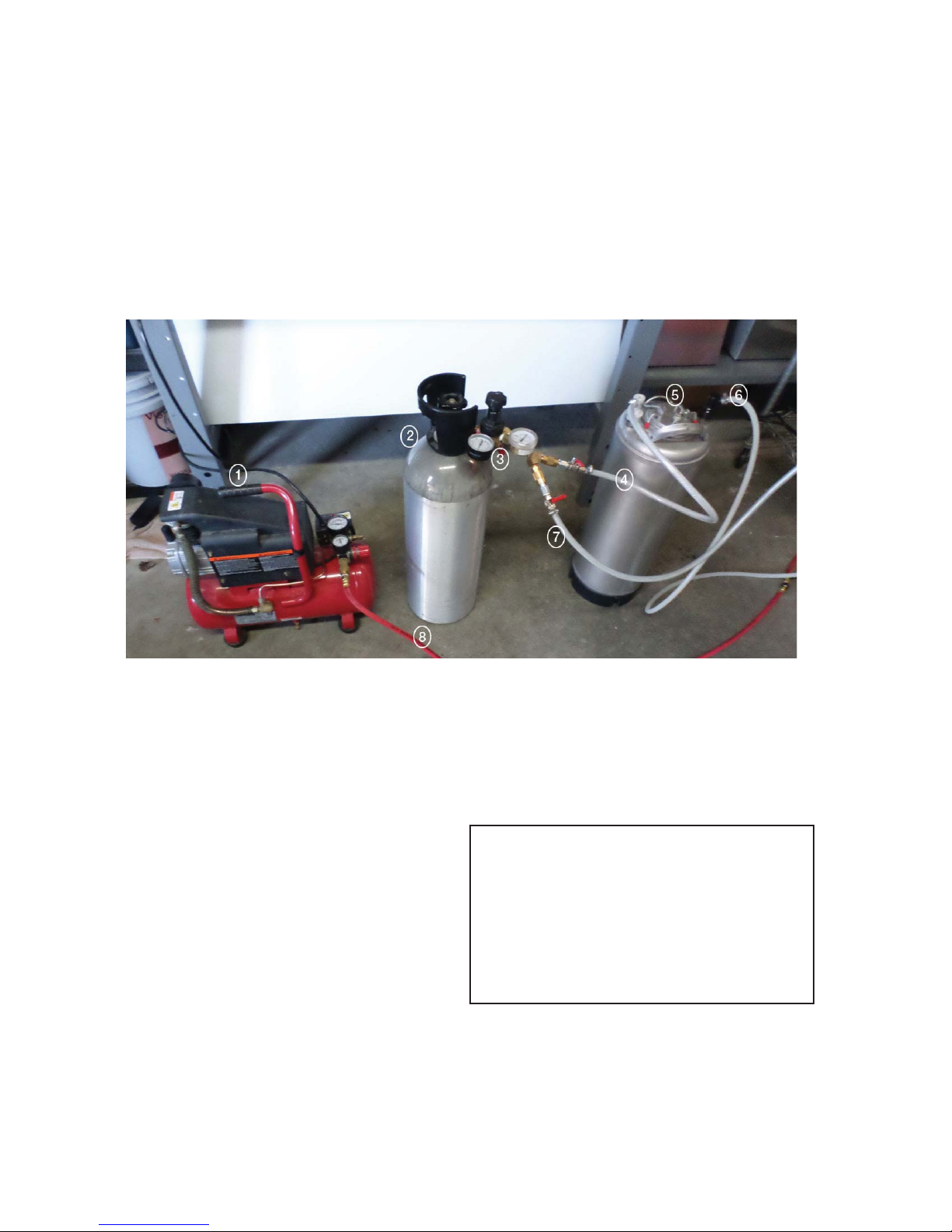
Air Compressor1.
CO2 Tank2.
CO2 Regulator3.
CO2 Line to Keg Inlet4.
Your First Bottle
Figure 2
Pressurized Keg5.
Line to “Inlet” input on Filler6.
CO2 line to “CO2 input on Filler7.
Compressed are line to “Air” input on Filler8.
e maximum recommended operating pressure
for the CO2 and air compressor are listed to the
right. Please keep in mind that varying
temperatures and product properties will mean
that adjusting the pressures will be necessary
for your product. You are encouraged to adjust
these pressures carefully until you nd a
combination that works for your product and
bottling environment.
265 Prado Road, Suite 1 • San Luis Obispo, CA 93401 • Tel: (805) 541-0100 • sales@xpressll.com
Air: 30 psi recommended
CO2: 30 psi recommended
Warning: Please follow the recommended
settings of the equipment you are using.
Exceeding manufacturer recommended
settings may result in injury to self and
others, as well as damage and/or failure
of the machine.
Page 8
5 | XPRESSFILL Systems LLC
Operating Procedures
4
Step By Step
You will fi rst want to unpack your fi ller 1.
from the shipping box and spread the
components out on a large fl at surface.
Make sure that you also have the following:
i. CO2 tank with regulator and connecting
tubes (we recommend a wye as well, see
setup diagram for details).
ii. Air compressor and hookup tubings
iii. A small (.5 liter or so) catch container
for collecting vented liquid
Place your ller on a at surface where you
2.
plan to bottle, ensuring that you have access
to a standard wall outlet or extension cord.
3.
Attach the support legs by sliding the legs
between the enclosure and rubber feet.
Begin by plugging the provided power cord
4.
into your machine, and then plug it into the
wall outlet. Flip the Power Switch on the
right side up to turn the ller on. Make sure
the cleaning switches on the left side are in
the down position (Fill Mode).
Toggle the fill switches to the full up
5.
position (Start Fill Position). Wait a few
seconds to verify that the green ll light
illuminates.
Make sure the Pressure Relief Knob is pushed in.
8.
1.Bottle ll
indicator light
Bottle Pressure
Adjustment
Start Fill
Stop Fill
Bottle Release
Pressure Release
2. Bottle pressure
adjustment knob
3. Fill toggle
switch
4. Pressure release
knob
6.
Flip the ll switch back down to the Release
Bottle position (the green ll light will go
o).
7.
Once you are sure the ller is powering up
properly, turn o the power switch on the right
side.
265 Prado Road, Suite 1 • San Luis Obispo, CA 93401 • Tel: (805) 541-0100 • sales@xpressll.com
Page 9
XPRESSFILL Systems LLC | 6
14.
e valves on the tanks should
be o for steps 9-11.
Turn on your machine by flipping the power
switch on the right side of your machine so
that is it lit up.
You are now ready to place a bottle on your
Cleaning switches
15.
machine. While pressing down on the Bottle
Foot Rest, place a bottle on the Bottle Foot
Rest and allow the return spring to lightly
hold the bottle against the stopper.
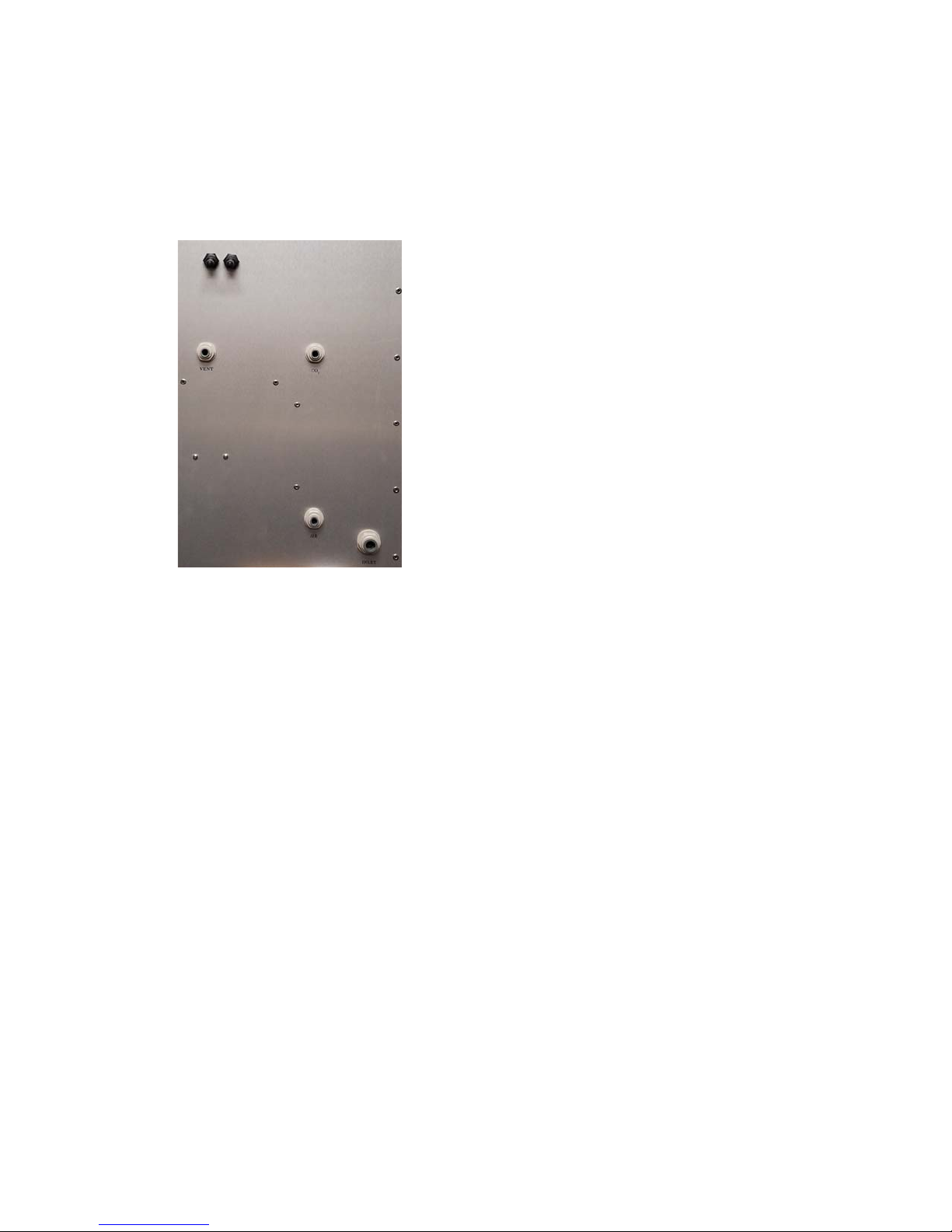
Vent
CO
2
Note: During the purge process, the bottle
will temporarily unseat from the stopper to
allow air to escape.
16.
Make sure the Pressure Release Knob is pushed in.
Always keep your hands clear of the bottle and
foot rest during step 17.
Flip the Fill Switch to the full up position.
17.
Air
Inlet
e ller will purge the bottle for a few
seconds, after which the Bottle Foot Rest will
immediately lift the bottle into a sealing
position against the stopper and pressurize
Plug the hose from your liquid container
9.
the bottle.
into the port marked “Inlet” on the left side
18.
of the machine using one of the provided
3/8” barbed ttings.
See “Adjusting Pressure” on page 7.
After the purge and bottle pressurization, the ll
light will come on and liquid begins to ow into
the bottle. If no ow is visible, then the Pressure
Relief needs adjustment. See Adjusting Pressures
10.
Plug one end of the provided 4’ x 1/4” tube
into the port marked “Vent” on the left side
of the machine, and place the other end into
your catch basin.
in the following section.
Repeat steps 15 - 18
for the other spouts.
11.
Plug your air compressor into the port
marked “Air” on the left side of the machine
using one of the provided 1/4” barbed ttings.
See “Adjusting Pressures” on page 7.
12.
Plug your CO2 tank into the port marked
“CO2” on the left side of the machine using
one of the provided 1/4” barbed ttings.
13.
Once you are sure that all components are
plugged in correctly, you can open the valves
on your tanks and turn on the air compressor.
265 Prado Road, Suite 1 • San Luis Obispo, CA 93401 • Tel: (805) 541-0100 • sales@xpressll.com
Once the green fill light deactivates, put the Fill
19.
Toggle Switch to the middle position (do not ip
to the full down position) and pull the Pressure
Release Knob.
Hold the bottle with one hand and ip the Fill
20.
Toggle Switch to the full down position to
release air in the pneumatic ram and remove the
bottle.
Congratulations!
You have now lled your rst bottles
using the XF4500 Filling System.
Page 10

XPRESSFILL Systems LLC | 7
Adjusting Pressures
It is the pressure dierential between keg/brite tank pressure and bottle pressure that
determines the rate of lling, amount of foam and retention of CO2 in your product.
erefore, adjusting either or both pressures can result in a more favorable ll.
Each spout must have its bottle pressure set individually. 1.
2.
e pressures during lling are adjusted to obtain a quick rate of lling with limited foaming.
Excessive foaming will trigger the ll sensors and stop lling prematurely. e bottle will begin
lling again as the foam settles, but this signicantly slows down the lling rate.
Typical maximum inlet pressures from a keg or brite tank are 30 psi and 15 psi, respectively.3.
Turning the Bottle Pressure Knob counterclockwise will start venting the pressure in the
4.
bottle and allow product to ow into the bottle. e more the bottle vents, the quicker it
will ll, but foam can start to develop. e Bottle Pressure Knob can be adjusted to achieve
an acceptable rate of ll as evidenced by the visual presence of limited foaming.
e inlet pressures can also be adjusted in conjunction with bottle pressures to change the
5.
lling rate and foaming characteristics.
265 Prado Road, Suite 1 • San Luis Obispo, CA 93401 • Tel: (805) 541-0100 • sales@xpressll.com
Page 11
8 XPRESSFILL Systems LLC
5
If at any time you have issues with the setup or adjustment of your XF4500 bottle fi lling machine,
or any other questions about fi lling your product, please contact us at the number listed at the
front of this manual. We are always happy to assist you.
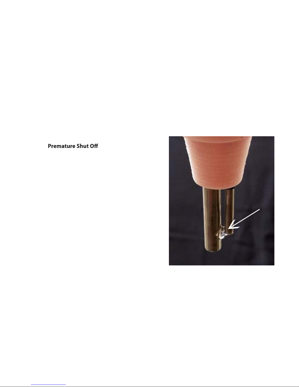
e XF4500 is a Level Fill machine, meaning when
liquid touches a spout and the probe, it will
automatically shut o. If moisture is allowed to
collect between the spout and the probe, the ller
will shut o prematurely, stopping the ll or not
allowing the ll to begin at all. is is evidenced by
the green LED ll indicator light ashing once
quickly and then staying o as the machine
“senses” a full bottle is in place.
Trouble Shooting
Dry the area between the spout and the probe with
a clean towel or use the compressor to air dry.
Once completely dry, the ll can resume. Isopropyl
alcohol is very good for cleaning and is fast drying.
Excessive Foaming
Excessive foaming is usually the result of:
i. too much pressure dierence between the keg pressure (inlet pressure) and the bottle
pressure, or
ii. too high a lling temperature.
Turning the Bottle Pressure Adjustment Knob clockwise will increase the bottle pressure and
reduce foaming. e higher the bottle pressure and lower the temperature, the more CO2
will stay in solution.
265 Prado Road, Suite 1 • San Luis Obispo, CA 93401 • Tel: (805) 541-0100 • sales@xpressll.com
Page 12

XPRESSFILL Systems LLC | 9
Cleaning
6
Cleaning your XpressFill is quick and easy, and is the single most important maintenance you can
administer to ensure long life and solid performance from your fi ller. Please use extreme caution
when using any cleaning product.
For general cleaning, we highly recommend a product called PBW by Five Star Chemicals. It
is safe, fast, and e ective, and our customers have been happy with the results. To clean your
XpressFill, begin by fl ushing your fi ller with 2 gallons of plain warm (not boiling) water from a
pressurized keg, which is pressurized with air. Follow that with a 3-gallon mix of PBW cleaner,
and let the PBW sit inside your fi ller for a few minutes in order to do its cleaning job. Follow the
cleaning with a sanitizer.
For sanitizing, we recommend Saniclean, from the same manufacturer. Saniclean has lowfoaming characteristics, is highly e ective, and completely food grade if diluted correctly per the
manufacturer’s instructions. Use the sanitizer with about 3 gallons of water, and follow the steps
according to the manufacturer’s instructions. After sanitizing, fl ush your fi ller with 2 gallons of
warm water. Before storing your XpressFill fi ller, make sure you get all water out of the fl ow path.
Allow to run until pressurized keg with cleaning solution is empty and runs dry, blowing the
remaining water out of the fi ller vent.
See instructions on the following page.
1
2
8
4
265 Prado Road, Suite 1 • San Luis Obispo, CA 93401 • Tel: (805) 541-0100 • sales@xpressll.com
3
5
6
7
Page 13
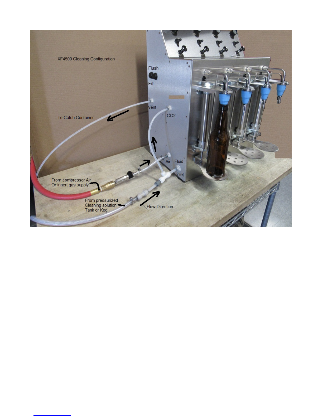
XF4500 Cleaning Configuration Part One
Attach cleaning hoses as pictured above. Tubing and connectors are supplied in the power cord bag.
1. Flip the Fill/Flush switches to flush mode (Rocker switches located left of machine).
2. Place bottles under spouts.
3. Turn on the main power switch (Green rocker switch located right side of the machine).
4. Turn on spout switch, full on position all the way up. Pull the pressure release knob to allow
flushing through vent area. Also turn the pressure release knob on top counter clockwise to open
up the valve for fast flow.
5. Let solution fill the bottle completely and allow it to run for a while after full.
6. Turn the spout switch to the middle position (stop fill).
7. Turn on the spout switch again all the way up (This runs the purge cycle again and allows the
CO2 flow path to be cleaned as well) Repeat step 7 a few times.
8. When satisfied with the cleaning put the Fill/Flush switches back to Fill mode (down).
9. Turn off the spout switch completely. This will allow you to remove the bottle and empty it of
the remaining cleaning solution.
10. This is the end of part one of the two part process for cleaning your machine.
Page 14
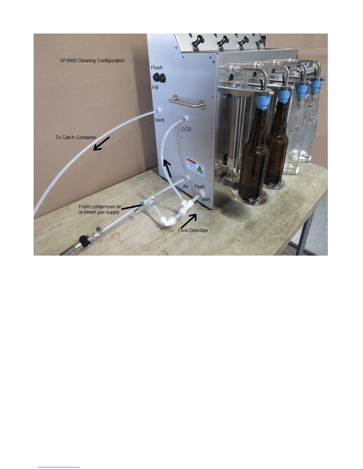
XF4500 Cleaning Configuration Part Two
Attach cleaning hoses as pictured above. Tubing and connectors are supplied in the power cord bag.
1. Turn on main power switch with bottles in place. (Green switch located right side)
2. Push in to close quick release knobs.
3. With gas line on turn on spout switch and allow gas to flow through the filling system.
4. Turn spout switch to middle position, and then back up to full on position. Repeat this several
times to allow the purge path to ventilate completely.
5. Turn the release pressure knob at top of machine clockwise to close valve about half way,
approximately ten turns.
6. Pull open the quick release knob for maximum ventilation through that flow path.
7. When you are satisfied with the results turn off the spout switch and remove the bottles.
8. Turn off the air/gas supply and remove all the hoses.
9. Turn off the machine.
Page 15

9 | XPRESSFILL Systems LLC
Additional Information
Our llers use “Push-To-Connect” type connectors which are standard in the beverage industry.
1. Installation simply requires pushing a tube into the tting and pulling lightly to check that the
connection is secure.
2. Removal requires using the included tool to rmly push the collet and remove the tube.
265 Prado Road, Suite 1 • San Luis Obispo, CA 93401 • Tel: (805) 541-0100 • sales@xpressll.com
Push the collet in
to remove tubing
 Loading...