

Page 1
User’s Manual
EN
v.b2
www.xprgroup.com
24
Visual Plus Corporation, s.a.
Drève Richelle 161
WOP G - Bte 34
1410 Waterloo - Belgium
BIOPROX-MF Biometric Mifare Reader
This product herewith complies with requirements of EMC directive
2014/30/EU. In addition it complies with RoHS directive EN50581:2012
Page 2

2
www.xprgroup.com
23
www.xprgroup.com
1. DES CRIPTI ON
2. SPE CIFICATI ONS
3. MOU NTING
4. WIR ING
5. CON NECTIN G BIOME TRIC R EADER S TO EWS C ONTROL LER
5.1 CON NECTIN G BIOME TRIC RE ADERS I N SAME R S485 LINE W ITH THE EWS CON TROLLE RS
5.2 CON NECTIN G BIOME TRIC RE ADERS W HEN ALL THE CON TROLLE RS HAVE TC P/IP COMM UNICATIO N
6. CON NECTIN G BIOME TRIC R EADER S TO 3RD PA RTY CON TROLLE R
6.1 CON VERTERS PIN DES CRIPTI ON
7. ENR OLLMEN T
8. CON FIGURI NG THE BIOME TRIC R EADER S IN PRO S SOFTWA RE
8.1 ADD ING BIO METRIC READER
8.2 ENRO LLING FINGER PRINTS FROM A R EADER
8.3 ENRO LLING FINGER PRINTS FROM DE SKTOP RE ADER
8.4 DEL ETING F INGERP RINTS
8.5 UPLO ADING T HE FING ERPRIN TS TO TH E BIOME TRIC RE ADERS
8.6 FIR MWARE UP DATE
8.7 ENT RY MODE
8.7.1 Card or Finger
8.7.2 Card and Finger
8.7.3 Finger Only
8.7.4 Finger on Card
8.8 SEN D CONFI GURATION
8.9 ADVAN CED SET TING
9. CON FIGURI NG THE BIOME TRIC R EADER S IN BIO MANAGE R
9.1 ADD READER
9.2 EDI T READE R
9.3 DEL ETE REA DER
9.4 CAL IBRATE SE NSOR
9.5 ADD USER
9.6 EDI T USER
9.7 DEL ETE USE RS
9.8 ENRO LL FIN GERS
9.9 UPLO AD FING ERPRIN TS TO REA DER
9.10 DEL ETE FIN GERPRI NTS
9.10.1 Deleting one user from the biometric reader
9.10.2 Deleting all users from the biometric reader
9.11 COMP LEX US ER UPLOA D
9.12 CUST OM WIEG AND
10. WIE GAND PR OTOCOL DE SCRIPT ION
11. SAF ETY PRE CAUTIO NS
12. TRO UBLESH OOTING
Contents
3
3
4
5
5
6
6
7
7
8
8
8
9
10
11
12
11
12
12
12
12
14
14
15
15
16
17
17
17
17
18
18
18
19
19
19
19
20
21
22
22
13
Page 3
1. DES CRIPTIO N
2. SPECIFICATIO NS
3
www.xprgroup.com
22
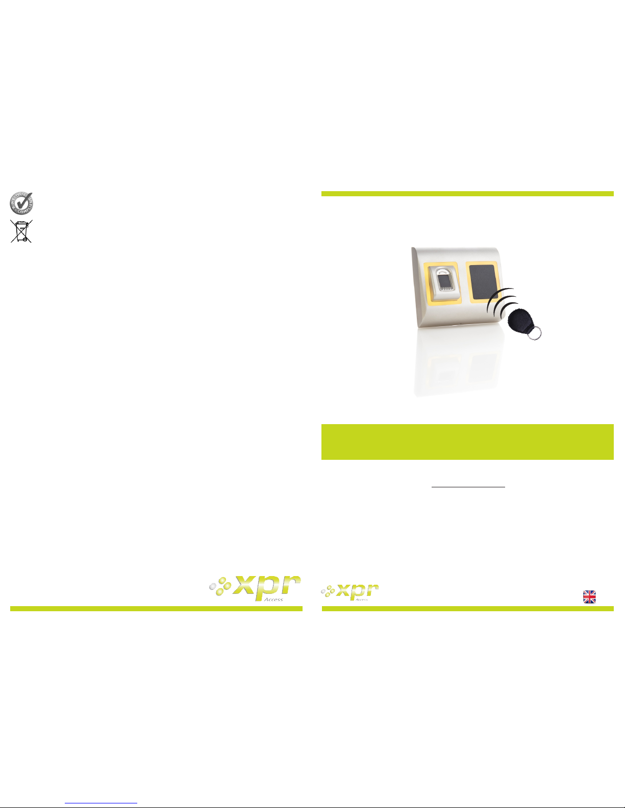
BIO PROX-MF is a Wiegand biometric and proximity reader for access control applications with programmable
wiegand output. It offers storage of up to 9500 fingerprints, it reads Mifare Classic 1K & 4K, Ultralight, Desfire
cards/tags and has a programmable Wiegand Output (8 to 128 bits).
The tamper switch output can trigger the alarm system, if an attempt is made to open or remove the unit from
the wall.
www.xprgroup.com
11. SAFETY PREC AUTI ONS
Do not install the device in a place subject to direct sun light without protective cover.
Do not install the device and cabling close to a source of strong electro-magnetic fields like radio-transmitting antenna.
Do not place the device near or above heating equipments.
If cleaning, do not spray or splash water or other cleaning liquids but wipe it out with smooth cloth or towel.
Do not let children touch the device without supervision.
Note that if the sensor is cleaned by detergent, benzene or thinner, the surface will be damaged and the fingerprint can't
be entered.
12. TRO UBLESHO OTIN G
Enrollment from desktop reader can be done, but the
Fingerprints are not sent to all Biometric Readers
in the network
·Check the Ser.No of the Readers.
·Check if proper termination is done as described before
Check if the Communication wires (A & B) are properly
connected to the reader
The Biometric Reader is not powered ON.
The tricolour LED is OFF.
Check the power Supply (red & black wire)
Fingerprint (or Card) is recognized (the tricolor LED is
green), but the controller reports other ID number and
the access is denied
·If the user is not deleted from the reader and the same
user is enrolled again with new ID, the reader will
recognize the finger with the first ID. To resolve this,
delete all users from the reader and upload all users to
the reader
·Check the Wiegand Bus (yellow & white wire)
·Check if the ground of the controller and the Biometric
Reader is the same
Check if the length between Biometric Reader and the
controller is less than 50 m
Electro static discharge influences the Fingerprint
Scan.
Connect the housing of the Biometric Reader to the
earth wire
Reader reading performance is decreased
·Check if fingerprint reading area is dirty. Do not clean
the device with any form of liquid. Use soft and dry
cloth only
Reading area is damaged. If the damage is minor, try to
calibrate the sensor
Fingerprint is not recognized normally
·Retry after drying the wetness of your finger
·When your finger is too dry, touch your forehead and
try again
When you have a cut on your registered finger, register
another fingerprint
The Proximity of the Biometric Reader is not working
The operation Mode of the Biometric Reader is set as
“Finger”. Please select “Card OR Finger” mode
Tags are working correctly, finger scan does not work.
·Fingerprint Sensor malfunction
·Check the Sensor position and its physical condition
Reset the system. Contact your installer
Technology
Authentication
Interface
Protocol programming
Fingerprint Sensor Type
1:1000 identification
Fingerprint enrolment
Panel Connection
Green and Red LED
Buzzer
Consumption
Power supply
IP Rating
Operating Temperature
Dimensions (mm)
Biometry and Mifare (13,56Mz)
Finger, Card, Finger or/and Card, Finger on Card
Wiegand 8 to 128 bits; Default: Wiegand 26bit
By PRO S software (EWS system) and BI OMAN AGER (all access control systems)
Capacitive
970 msec, including feature extraction time
On the reader or from the USB desktop reader (B IOE)
Cable, 1m
Externally Controlled
Yes
Max. 200mA
65
9-14V DC
-15°C to +50°C
100 x 94 x 30
Housing
Colour
ABS
Silver, Red, Green, Dark Grey, Blue, White
Cable distance 50m
Backlight ON/O FF
Yes, by software settings
Fingerprint capacity up to 9500 fingerprints; unlimited in Finger on Card mode
Fingerprints per user 1-10 fingerprints
Tamper Yes
Proximity reading type Mifare Classic 1K & 4K, Ultralight, Desfire; Finger on Card (Classic and Desfire)
Reading distance 1.5 to 5.5cm
Page 4
4
www.xprgroup.com
For more information please refer to BioManager User Manual
21
3. MOUNTI NG
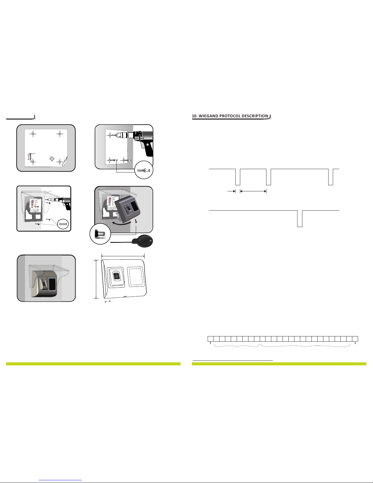
If the biometric reader is installed and used outdoor, the reader MUS T be fitted with the MC D-MINI
polycarbonate cover available in our accessories in order to protect the sensor from direct rainfall. The
operating temperature of the product is between -15ºC - + 50ºC. If the reader is installed in an environment
where the temperature can drop below -10ºC or/and if the sensor could only be exposed to direct sunlight, it is
strongly recommended to install the reader inside a third party sealed wall mount box (fitted with additional
heater if very low temperature) to keep a constant sensor level performance. XPR™ cannot guarantee the
functionality of the product if measures and advice before are not followed.
It is also strongly recommended to use double technology biometric readers when use outdoor to offer first
higher security but also the possibility to use different readers depending on users.
www.xprgroup.com
10. WIEGAND PROTOCOL DESC RIPTION
The data is sent over the lines DATA 0 for the logic “0” and DATA 1 for the logic “1”. Both lines use inverted logic,
meaning that a pulse low on DATA 0 indicates a “0” and a pulse low on DATA 1 indicates a “1”. When the lines
are high, no data is being sent. Only 1 of the 2 lines ( DATA 0 / DATA 1 ) can pulse at the same time.
Example: data 0010....
D0
D1
5V
0V
100 us
1 ms
0 0
1
0
5V
0V
Data bit 0 = approximately 100 us (microseconds)
Data bit 1 = approximately 100 us (microseconds)
Time between two data bits: approximately 1 ms (millisecond). Both data lines (D0 and D1) are high.
Description for the 26 bits Wiegand format
Each data block consists of a first parity bit P1, a fixed 8 bits header, 16 bits of user code and a 2nd parity bit P2. Such a data block is shown
bellow:
Parity bit (bit 1) + 8 bits header + 16 bits user code = 2 bytes + Parity bit (bit 26)
P1 P2XXXX XXXX XXX XYYYY YYYY YYYY
Example: 170 31527
1 0 1 0 1 0 1 0 1 0 0 1 1 1 1 0 1 1 0 0 1 0 0 1 1 1
Note: Parity bits are calculated as follows:
P1 = even parity calculated over the bits 2 to 13 ( )X
P2 = odd parity calculated over the bits 14 to 25 ( )Y
E AAA A A AAABB B B B B B B B B B B B B B B O
Even
Parity
Bit
Odd
Parity
Bit
Site Code User Code
100 mm
94 mm
30 mm
Cable
Ø6.0
30mm
ATPD-MINI
Page 5
5
www.xprgroup.com
20
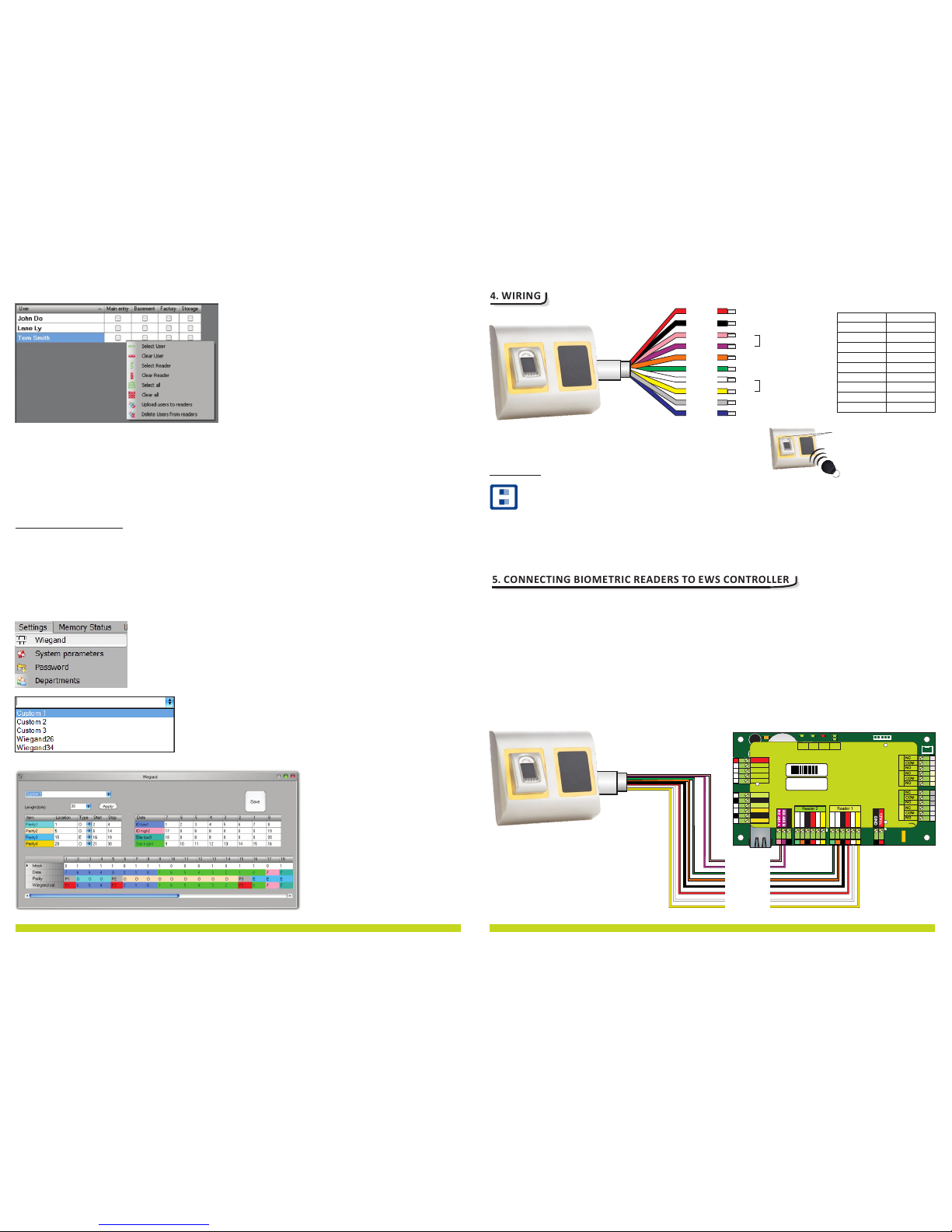
4. WIRING
LD16
R55
C41
C28
L2
R36
LD20
R18
R25
R24
C40
R10
C34
L10
L11
C18
C33
R9
C42
C1
R5
R45
C43
C44
R28
R21
C45
D13
LD14
R46
C3
C5
R38
ZD3
C29
L9
LD13
R14
ZD4
C32
R19
R37
A
LD17
A
LD19
A
LD18
L7
C27
L6
C16
C15
RX4
D5
D10
R32
R33 R35
R49
IC6
ZD5
ZD6
R22
L3
R53
R34
TAS1
IC11
R15
IC15
R3
R4
L8
R47
FUSE1
IC8
R20
R16
R11
C2
X1
C4
IC7
ICN2
R1
C13
C12
ICN1
R23
R48
A
LD5
RE1 RE3
A
LD8
X3
IC1
C6
U5
L5
L4
RE4RE2
A
LD6
A
LD9
ZD2
LD15
R13
ZD1
R54
R50
R6
IC12
R17
R7
R62
A
LD23
D3
D2
RX3
J1
Rb6
R2
LD21
IC2
H1
A
LD22
BAT
U1
IC5
FUSE2
IC3
U4
A
A
IC1
A
AAA
Earth
screw
Free Led 1
Free Led 2
GND
12V out
D0
D1
Free Led 1
Free Led 2
GND
12V out
D0
D1
Door Sensor2
Door Sensor1
Exit Button1
Exit Button2
GND
GND
Free In 2 -
Free In 2 +
Free In 1 -
Free In 1 +
Rx
Tx
Busy
System
OK
Door 1 Door 2
Free Out 1 Free Out 2
TCP/IP
Earth
12Vdc Out
12V
gnd
D1D012V
gnd
led2led1
12V
IN1
IN1
IN2
IN2
+
-
+
-
D1D012V
gnd
led2led1
PB2
PB1
DS2DS1
gnd gnd
COM
NC1NO1 NC2NO2
COM
COM
NC3NO3 NC4NO4
COM
GND
BA
gnd
Fuse
Ser No: 11-04-16-013
Mac: 00-04-A3-16-90-D
RoHS
33 6 11 1 01 31
50m. max
5. CONNECTING BIOMETR IC READE RS TO EWS C ONTROLLER
- The Biometric readers can be connected to virtually any controller that conforms to Wiegand format
standards (standard Wiegand 26bit or self-defined Wiegand).
- The lines D0 and D1 are the Wiegand lines and the Wiegand Number is sent through them.
- The RS485 line (A, B) is used for fingerprint transfer and reader settings.
- The Biometric readers must be powered from the controller.
- If you use different power supply for the biometric reader, connect the GND from the both devices to ensure
correct transfer of the wiegand signal
- Fingerprint enrollment is done from the PC Software. Connection between the Biometric readers and the PC
must be established.
pink
violet
green
orange
black
B
LGLR-
GND
A
red
white
yellow
+12V
D0
D1
www.xprgroup.com
Use mouse click to select the combination you need or use right-click to check or clear entire row or column
Select Upload Users to readers or Delete Users from readers at right-click menu
As upload is progressing, check boxes are cleared mining appropriate combination was successfully done
When upload is over, if there are still checked items, repeat the upload command
9.12 CUS TOM WIEG AND
BioManager has defined Wiegand 26 and 34 bit as standard options and other 3 Wiegand settings as user
definable.
To setup custom Wiegand format
Select Wiegand menu from Settings
At Wiegand setup window select one from customs Wiegand
Set Wiegand parameter
Click on Save button
Note:
Wiegand settings are out of
scope for common end user.
Please ask your installer to set
the parameters and do not
change it later.
B
12V DC
LED Green -
D0
D1
LED Red -
GND
A
Tamper
Tamper
RS485
WIEGAND
LRLG-
Tricolor LED (Red, Green, Orange)
12V DC
GND
Tamper
Tamper
Tamper Switch(NO)
9-14V DC
ground
D1
D0
Data 1
Data 0
LR-
Red LED -
LG-
Green LED -
A
B
RS485 A
RS485 B
Tamper Switch(NO)
Orange
Yellow
Red
Black
Pink
Violet
Green
Gray
Blue
White
Note: The conversion from 7byte ID to 4 byte ID is only possible with cards that have 7 byte ID Number.
Those are: Mifare plus, Desfire and Ultralight. The number is converted according to NXP algorithm. It
corresponds to the number obtained by the USB desktop reader PR OXE.
1 2
ON
1 - Convert 7byte UID to 4byte UID
DIP Switch
2 - not used
Page 6
6
www.xprgroup.com
19
TCP/IP
50m
max.
50m
max.
50m
max.
Switch
RS485
1 km max / 32 Units (EWS + Biometric Readers)
50 ohm
50 ohm
TCP/IP
gnd
gnd
Jumper for
RS485 termination
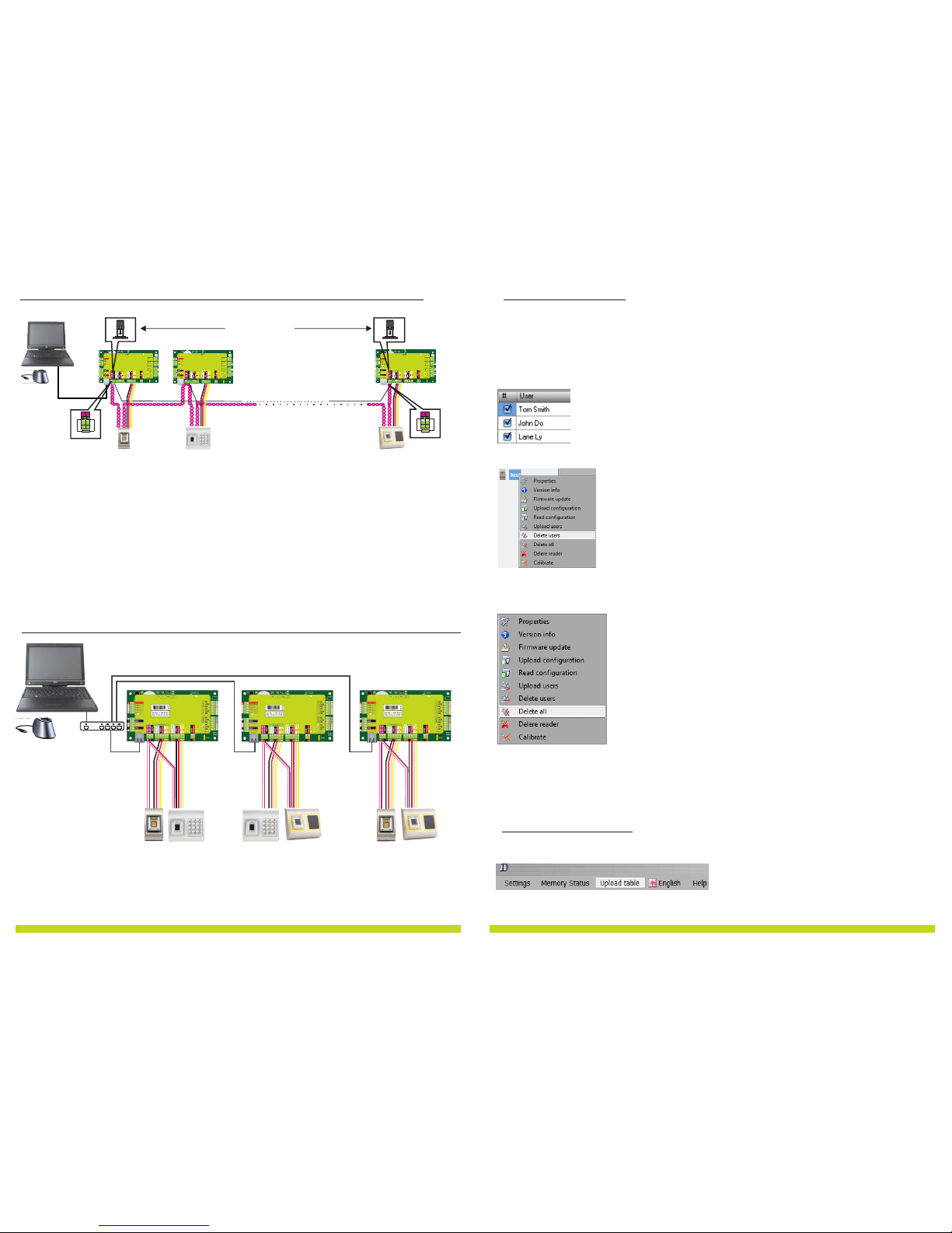
5.1 CON NECTIN G BIOMETRIC READ ERS IN S AME RS485 L INE WIT H THE EWS CONTROLLERS
The Biometric readers are connected through RS485 bus. The same RS485 bus that the EWS controllers are connected to.
Maximum units in one network (EWS + Biometric readers) is 32.
If there are more than 32 units in one network, please utilize RS 485 HUB to connect.
The RS 485 Line should be configured in the form of a daisy chain, N OT in a form of a star. If star must be used in some
points, keep the stubs from the RS 485 backbone as short as possible. Maximum length of the stub is dependant of the
installation (total number of devices in RS485 line (total cable length, termination, cable type...) so recommendation is to
keep stubs shorter than 5 meters, keeping in mind that this can be possible reason for errors in communication with PC
software
The cable must be twisted and shielded with a min. 0.2 mm2 cross section.
Connect the ground (0V) of each unit in the RS 485 Line using a third wire in the same cable.
The shield of the communication cable between two devices must be connected to the EARTH from ON E side of the RS
485 Line. Use the side that has earth connection to the building’s grounding network.
5.2 CON NECTIN G BIOME TRIC READER S WHEN A LL THE C ONTROL LERS HAV E TCP/IP CO MMUNICATION
W hen all the controllers are connected via TCP/IP, then the RS485 network becomes local (from Reader 1 to the Controller
then to the Reader 2).
C onnect the readers directly to the Rs485 terminals in each controller.
I f the distance Reader-Controller is high (50meters) and if the communication with the reader can not be established, then
terminate the RS485 network by closing the jumper in the EWS Controller or as described in chapter 4 in EWS manual.
www.xprgroup.com
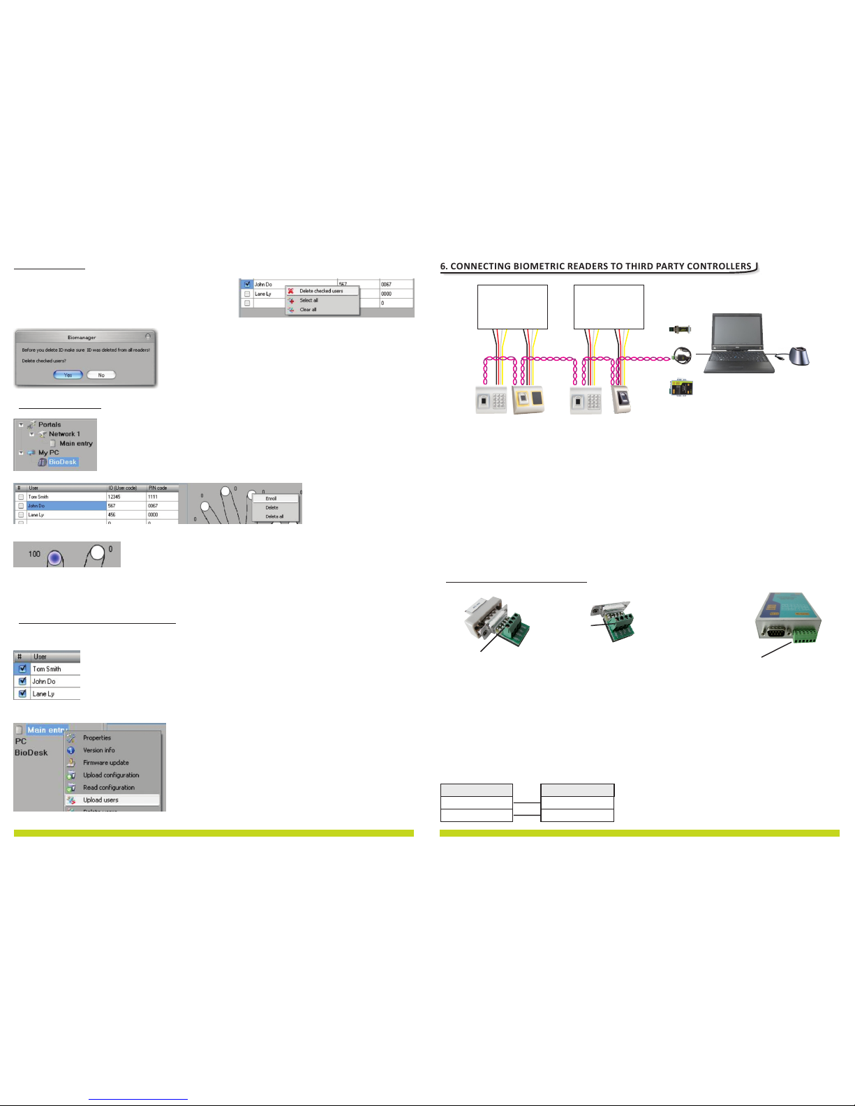
9.10 DEL ETE FINGERPRIN TS
After the transfer, the fingerprint are stored in the Biometric reader and in the PC.
Deleting can be done only in the software, only in the readers or from the both places.
9.10.1 Deleting one user from the biometric reader
Select the users checkbox.
Right click on the Reader and select Delete Users
The user is deleted from the reader, but his fingerprints are still in the software's database. They can be sent
ones again without the need of re enrollment.
9.10.2 Deleting all users from the biometric reader
Right click on the Reader and select Delete all
9.11 COM PLEX US ER UPLO AD
Complex user upload is used to sent multiply user selection to more readers
Click on Upload table at main menu
Page 7
7
www.xprgroup.com
18
www.xprgroup.com
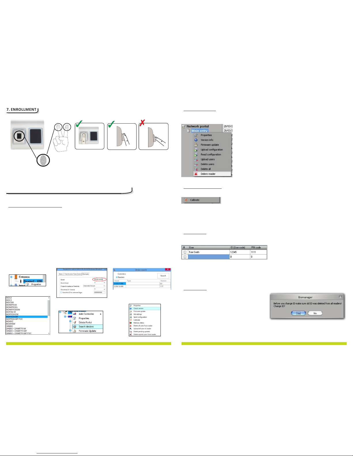
6. CONNECTING BIOMETR IC READE RS TO THIR D PARTY CONTROL LERS
Connect the lines D0, D1, Gnd and +12V to the third party controller.
Connect the RS485 Line (A, B) to the converter. Connect the converter in the PC.
Fingerprint enrollment is done from the PC Software. Connection between the Biometric readers and the PC
must be established.
The Biometric readers communicate with each other with a RS485 and with the P C Software through a
Converter.
The RS485 Line should be configured in the form of a daisy chain, NOT in a form of a star. Keep the stubs from
the RS485 backbone as short as possible (not more than 5 meters)
Only one converter per RS485 line is needed, not per reader.
Biometric Reader
Converter
RS 485 A
RS 485 B
PIN 1 (RS 485 +)
PIN 2 (RS 485 -)
CNV100
Converter RS485 to RS232
Does not requires installation
CNV200
Converter RS485 to USB
Requires installation as USB
serial device (refer to CNV200
Manual). The Drivers are located
on the CD.
CNV300
Converter RS485 to TCP/IP
Does not require installation. IP
address set through Internet
Browser(refer to CNV300
Manual)
6.1 CON VERTER S PIN DE SCRI PTION
PIN 1
PIN 1
PIN 1
BIOMANAGER Software
RS485
A
B
3rd party controller
- + D0 D1
- + D0 D1
3rd party controller
- + D0 D1 - + D0 D1
CNV100
CNV200
CNV300
BIOE
USB Desktop Reader
optional
Check the users to be deleted
Right-click on the users table
Click on Delete checked users menu
Confirm warning message
9.8 ENR OLL FIN GERS
Select the User in the User Column, not the check box (the check box is
for sending the fingerprints) and the User name cell will turn blue
Select the Biometric reader or Desktop reader BIOE from where the
enrollment will be done
Right click on the fingertip
and select Enroll
Swipe the finger on the Reader and the finger tip will become
blue, with percentage of successful enrollment given right
beside the fingertip
Note: If more fingerprints are added for one user, all fingerprints will send the same Wiegand Code to the controller.
9.9 UPL OAD FINGE RPRI NTS TO READ ER
Check the users which fingerprints will be sent to the Reader
Right-click on the Biometric reader those users should be sent and select Upload users
As each us er is be ing sent, t he checkbox will becom e
unchecked indicating that the user is successfully sent. In the
same time the orange LED of the Biometric reader blinks
Note: Average time for transferring one finger template is 0,6
sec.
Note: The PIN Codes are also being sent, if there are any.
9.7 DEL ETE USERS
Page 8
8
www.xprgroup.com
17
www.xprgroup.com
8. CONFIG URING TH E BIOMET RIC READERS I N PRO S CS SOFT WARE
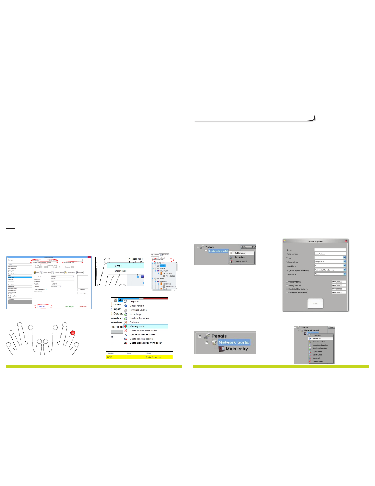
1. Expand the Door item to view the readers
2. Right click on the reader and select properties (8.1)
3. In the Basic tab, for “Type” of the Reader select “BIOP ROX-MF”. (8.2)
4. After selecting the type, a third tab will appear “Biometric”. Go to that tab and put the serial number of
the Biometric Reader. (8.3)
Important Note: The serial number of the reader can be found on a sticker inside the reader, on the
packaging box and it can be search from the software (right click on the portal/search devices/readers).
(8.4 & 8.5)
To check if the reader is On Line, right click on the reader and select “Check version”. In the Event Window
a message should appear “Device ON Line, Type: BI OPROX-M F” (8.6)
8.1
8.2
8.3
8.4
8.5
8.6
8.1 ADD ING BIOMETRIC R EADER
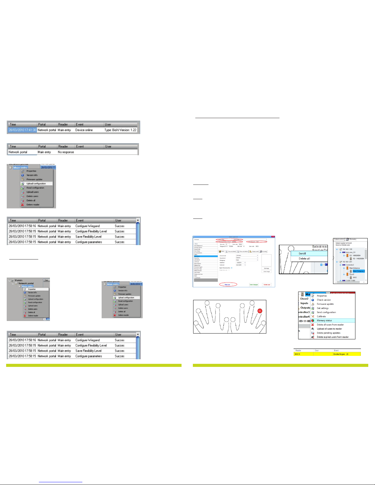
7. ENROLLMENT
9.3 DEL ETE REA DER
Right-click on the reader and select Delete reader
9.4 CAL IBRATE SENSO R
9.5 ADD USER
Right-click on the reader and select Calibrate
See the events panel to check the calibration flow
It is recommended to do sensor calibration once after reader is mounted. Clean the fingerprint sensor
before calibration.
At user table, click on the last empty user field and enter user name
Click on ID (User code) field and enter ID number. This number will be sent by the reader to the access
controller when user finger is recognized by the reader
Click on PIN code field and enter the PIN. PIN code is used at readers with keypad. When PIN code is typed
at reader, User ID will be sent to the access controller
9.6 EDI T USER
Find the user at user table to edit
Click on the user field for edit (Name, ID or PIN )
Type new value
Press Enter on the keyboard
Important:
When ID is changed, warning message is displayed reminding that if ID exist in some reader, should be
deleted from reader prior to change.
BIOPROX-MF
BIOC3
Page 9
www.xprgroup.com
9
16
www.xprgroup.com
8.7
8.8
8.9
8.11
8.10
8.12
1. Open the Users Window and create a new user.
Click on “New User ”, put a name, ID(card number). (8.7)
2. Go to the “Biometric” Tab
3. Select the reader(with left click) from which the enrollment will be done. (8.8)
4. Right click on the fingertip and select enroll. (8.9)
5. In the next 25 sec. present the finger on the selected reader and the finger tip will turn red, with the
percentage of successful enrollment shown next to the fingertip. (8.10)
In these 25 sec. the reader will continuously blink in orange.
6. Repeat point 4&5 for each finger that should be enrolled.
7. Click on “Save New” and the fingerprint will be sent automatically to all Biometric Readers where that
user has access, i.e. to all the readers according to the Access Level assign to that user.
Example:
If the user has “Unlimited” Access level then the fingerprints will be sent to all readers, if the user has
Access level only for Reader1 and Reader 3 then the fingerprints will be sent only to those two readers.
Note:
To check if all the fingerprints are sent to the reader, right click on the reader and select “Memory Status”.
(8.11)
In the event window a line will appear indicating the number of fingerprints stored in the reader. (8.12)
Note:
If more fingerprints are added for one user, all fingerprints will send the same Wiegand Code to the
controller, the one written in the field User ID(card Number).
8.2 ENR OLLING FING ERPRINTS FROM A READE R
If reader is online, right click on reader and select Upload configuration
Check at event table if configuration was successful
9.2 EDI T READE R
Right-click on the reader and select Properties
Edit reader properties and click Save button
Right click on the reader and select Upload configuration
Check at event table if configuration was successful
If reader is online, new line is added on top of the event table
If reader is not online, following line is added on top of the event table
Page 10
10
www.xprgroup.com
15
www.xprgroup.com
8.13
8.7
8.9
8.11
8.10
8.12
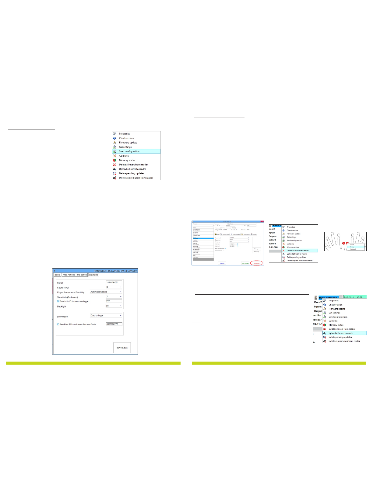
Plug the Desktop Reader (BI OE) in the PC. If the device is not installed automatically use the drivers located on
the CD provided with the Biometric reader. It is installed in the same way as a USB Device. When the desktop
reader has been installed it will automatically appear in the Software. (8.13)
1. Open the Users Window and create a new user.
Click on “New User”, put a name, ID(card number). ( 8.7)
2. Go to the “Biometric” Tab
3. Select the USB desktop Reader (with left click).
4. Place the finger on the BIO E, right click on the fingertip and select enroll. (8.9)
5. The finger tip will turn red, with the percentage of successful enrollment shown next to the fingertip. (8.10)
6. Repeat point 5 for each finger that should be enrolled.
7. Click on “Save New” and the fingerprint will be sent automatically to all Biometric Readers where that user
has access, i.e. to all the readers according to the Access Level assign to that user.
If the reader is off line, the fingers will be sent upon the connection is established between PRO S server and the
reader. No need for additional enrollment or actions. The fingerprints will be sent as soon as communication is
established.
Example:
If the user has “Unlimited” Access level then the fingerprints will be sent to all readers, if the user has Access
level only for Reader1 and Reader 3 then the fingerprints will be sent only to those two readers.
Note:
To check if all the fingerprints are sent to the reader, right click on the reader and select “Memory Status”. (8.11)
In the event window a line will appear indicating the number of fingerprints stored in the reader. (8.12)
Note:
If more fingerprints are added for one user, all fingerprints will send the same Wiegand Code to the controller,
the one written in the field User ID(card Number).
8.3 ENR OLLING FING ERPRINTS FROM DESKTOP READER
9 CONFIG URING TH E BIOMET RIC READERS I N BIOMAN AGER
BioManager is software for fingerprint management of XPR Biometric readers, when used with third party
access controllers.
Main functions:
- Fingerprint Enrollment
It can be done by ANY Biometric reader in the network or by Desktop (US B) Biometric reader.
Note: The Desktop Biometric reader BIOE is only compatible to Biometric readers with capacitive sensor,
not with the ones with thermal sensor.
- Fingerprint Transfer
Finger templates can be sent to any Reader in the Network. Different Users can be sent to different
Biometric readers.
- PIN Codes management and transfer
PIN Code length configuration (1 to 8 digits) and PI N Code transfer.
- Wiegand Output Configuration
The Wiegand output of the Biometric reader can be customized bitwise.
9.1 ADD READ ER
Right-click on the portal connected
to the reader and select Add reader
Fill the Reader form
Click on Save and the reader icon
appears under the selected portal
Right-click on reader and select
Version info
Page 11
11
www.xprgroup.com
14
www.xprgroup.com
8.14
8.15
8.16
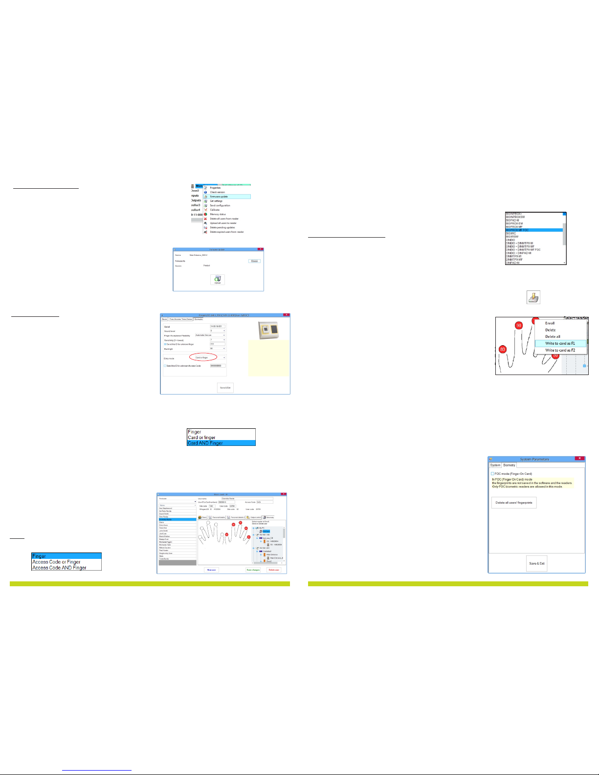
In General, the fingerprints are stored in the Biometric reader and in the Software.
Deleting can be done only in the readers or from both places.
Deleting one user from the biometric reader
Select the User
Click on “Delete User”. The User together with its fingerprints will be deleted from both the
software and the fingerprint readers. (8.14)
Deleting all users from the biometric reader
Right click on the reader and select “Delete all users from reader” (8.15)
Delete one or more fingerprints
Select the User and open the “Biometric” tab
Go to the fingertip that needs to be deleted, right click and select ”Delete” for one finger or
“Delete All” for all fingers of the User.
Click “Save Changes”.
With this procedure the User's fingerprints are deleted from the software and from the reader. (8.16)
8.4 DEL ETING FINGERPR INTS
Send This ID for:
Unknown Finger sends the desired Wiegand when an unknown finger is applied.
Sound level:
Sound level of the device (ON or O FF)
Finger Acceptance Flexibility:
Accepted tolerance. The recommended value is “Automatic Secure”.
Sensitivity:
Bio-sensor sensitivity, the recommended value is 7, most sensitive.
· Right-click on the reader and select the Send
configuration menu
· See the events panel to check the
configuration flow
Note: The biometric reader gets its settings
automatically. This function is used if the
reader was off line while making the changes.
8.9 ADVANCED SETT INGS
8.8 SEN D CONFIGURATION
Right click on the biometric reader
Select “Upload all users to reader”
While receiving the fingerprints the reader will blink in orange.
Note: Use this feature when you change or add a reader, if pending
tasks are deleted in the software or if there are doubts that fingerprints
in the reader memory are not synchronized with the software database.
In normal usage, the fingerprints are sent automatically and this feature
is not used.
8.17
8.5 UPL OADING TH E FIN GERP RINT S TO TH E BIOMETRI C READERS
Page 12
12
www.xprgroup.com
13
www.xprgroup.com
8.20
8.23
8.7 ENT RY MODE
8.21
8.22
Right-click on the reader and select Firmware
update menu (8.18)
On the Firmware update window, click on the
Browse button (8.19). The default location of the
firmware files installed with PROS CS is in the
folder "Firmware".
Select the firmware file with a "xhc" extension.
Click on the Upload button
Important: Wait for the update end message. Do
not turn off the reader, the software or any
communication device in between during the
entire process.
8.18
8.19
8.6 FIR MWARE UP DATE
Right click on the biometric reader
Select “Properties” and go to the “Biometric” tab
For Entry Mode select “Card or Finger” (8.20)
Note: All the fingers and the card will send the same
wiegand number (8.23)
Right click on the biometric reader
Select “Properties” and go to the “Biometric” tab
For Entry Mode select “Card and Finger” (8.21)
Use of the double security mode:
Present the card (ex. 88009016), in the next 8 sec. the
reader will blink in orange waiting for the finger.
Present the finger
8.7.2 Card and Finger
Right click on the biometric reader
Select “Properties” and go to the “Biometric” tab
For Entry Mode select “Finger” (8.22)
Note:
In this mode the proximity reader will become inactive.
8.7.3 Finger Only
8.7.1 Card or Finger
8.7.4 Finger on Card
Right click on the biometric reader
Select “Properties”
For “type” of the reader select “BIOPROX-MF FOC” (8.30)
Writing Template on the card
1. Open Users window
2. Select existing user or create new one
3. Enroll 1 or 2 fingers using BIOE USB Desktop Biometric Reader
4. Place the user card on the PROXE
5. Right click on the fingertip and select “Write to Card as F1” (8.31)
6. To put the second finger in the card, go to another fingertip and
select “Write to Card as F2”
7. If the fingerprints are not to be stored in the software database,
right click on the fingertip and select “Delete all”
8. If some user data other then fingerprints is edited or the
fingerprints should be saved in the software database, click Save,
otherwise go to another user or close the window if no other user
management is required.
Note:
Depending on the Mifare Card, 1 or maximum 2 fingers can be
written.1k Cards can store 1 fingerprint, 4K cards can store 2
fingerprints.
8.30
8.31
To use the “Finger on Card” mode:
Present the mifare card with written fingerprints in it, the reader will beep and blink.
Present the finger on the Biometric Reader
Note:
In “Finger on Card” mode, there is NO LI MIT on the capacity of the fingerprints, since the fingerprints are
stored in the user’s card, not in the biometric reader.
Note:
In “Finger on Card” Mode (FOC), the fingerprints are stored in the
card and in the software’s database.
If you want the fingerprints not to be stored in the database, then
tick the checkbox in: Settings/System Parameters (8.32)
8.32
 Loading...