

Page 1

Copyright© Vertical Leisure Ltd. 2019 Version 2.1 All rights reserved.
www.XPOLE.com
®
Instruction
Manual
Please Read Fully
Before Installation
Page 2
®
Copyright© Vertical Leisure Ltd. 2019 Version 2.1 All rights reserved.
CRITICAL INFORMATION - PLEASE READ
THIS BEFORE OPENING YOUR PACKAGE
To get the best from your XPERT Pro – with SAFETY being the utmost priority – it is extremely important that you READ &
FOLLOW the Instruction Manual from beginning to end and most importantly, understand it!
Prior to installation, all shrink-wrap covering the pole tubes and parts must be removed. Please DO NOT use
a sharp instrument/knife to do this, as damage may be caused to the pole surface.
Follow the simple but explicit instructions in this manual to get the best results from your pole.
Safety is a priority at all times.
If you have ANY questions – before you assemble, install or use your XPERT Pole – contact your point of purchase or see
the support/FAQ’s section on the X-POLE website for your region. www.xpole.com
ALL REMOVABLE AND PORTABLE POLES USE PRESSURE BETWEEN THE FLOOR AND CEILING TO KEEP
THEM STABLE. THERE IS A POSSIBILITY THAT DAMAGE COULD BE CAUSED TO THE CEILING.
VERTICAL LEISURE LTD, X-POLE INTERNATIONAL, X-POLE US INC, THEIR DISTRIBUTORS, SALES
PERSONS OR ANY OTHER PERSONS OR ASSOCIATED COMPANIES CANNOT BE HELD RESPONSIBLE FOR
ANY DAMAGE TO PROPERTY OR INJURY TO PERSONS OR THIRD PARTIES DURING THE USE OF THIS
PRODUCT.
BY REMOVING THE X-POLE XPERT PRO FROM ITS PACKAGING AND/OR ANY USE OF THE PRODUCT
CONFIRMS ACCEPTANCE OF THE ABOVE WARNINGS AND THE USER’S RESPONSIBILITY IN USING THE
PRODUCT.
IF YOU DO NOT ACCEPT THE TERMS SET OUT ABOVE THEN:
DO NOT REMOVE THE XPERT PRO POLE FROM ITS PACKAGING OR ATTEMPT TO ASSEMBLE, INSTALL OR USE
THE PRODUCT.
Contact your point of purchase to arrange a return & refund (shipping costs may still apply). The product must be returned
unused & in its fully packaged state.
CAUTION: The XPERT Pro Pole SHOULD NOT be installed under false, suspended or non-rigid
ceilings. When searching for Joists please use a step ladder and have a second person holding
the ladder providing additional assistance.
2
CAUTION: Take note that carpet, wooden or sprung floors can affect the stability of this product.
CAUTION: Never undo any of the screws unless you are explicitly told to do so in the instruction
manual.
Page 3
®
LEADERS IN POLE & AERIAL FITNESS
Copyright© Vertical Leisure Ltd. 2019 Version 2.1 All rights reserved.
Welcome
Thank you for purchasing an XPERT Pro Pole. The team at
X-POLE have spent a significant amount of time researching,
designing and developing it.
We want this product to be the world’s leading Exercise and Dance
Pole, if it’s not; we want to understand why not! At X-POLE we thrive
on constructive criticism and suggestions! So contact us (details on
the back cover) if you have any comments or suggestions on how to
improve the product
®
Before using your pole
Mis-using a pole can be dangerous, not only to the user but also to anyone close to the pole. The use of a dance pole is
always at the user’s discretion, and it is the user’s responsibility to check the pole is installed correctly & safely before use.
Pole Exercise is extremely physical and uses muscles that you will not have used before and therefore if you are not
warmed up; muscle damage, strains and injury can occur. Before using the pole it is mandatory to warm up and, after
use, cool down.
It is highly recommended that before you use your XPERT Pole you review some online videos to learn the basic moves.
Never try moves beyond your ability without an instructor. If at any time whilst using your pole you feel uncomfortable,
your muscles hurt, or you are short of breath – take a break. Always rest between moves & exercise sensibly, if you
experience any health issues, seek medical advice.
Have fun with your X-POLE XPERT Pro. The X-POLE Team.
What to wear
Clothing
When it comes to clothing – less is best (unless you have purchased either a Powder Coat or Silicone Pole).
So try to keep your arms and legs uncovered. Pole work needs the friction created by skin contact, so
T-Shirts, Crop Tops & Shorts are best. However, you must feel comfortable so wear what you feel relaxed in
(tracksuit bottoms, etc.) even though this may mean you are unable to do some of the pole moves properly
because of grip.
Footwear
Again comfort is essential. Bare feet (recommended), dance shoes, or trainers can be used but trainers have
high friction, so a trainer with a smooth as possible sole is recommended.
Oils and Lotions
NEVER use oils and/or lotion on your hands or body prior to using your pole. This is very DANGEROUS. The
oil can transfer onto the pole making it slippery and impossible to hold and this could cause you or someone
using the pole after you to have a serious accident.
3
Page 4
®
Copyright© Vertical Leisure Ltd. 2019 Version 2.1 All rights reserved.
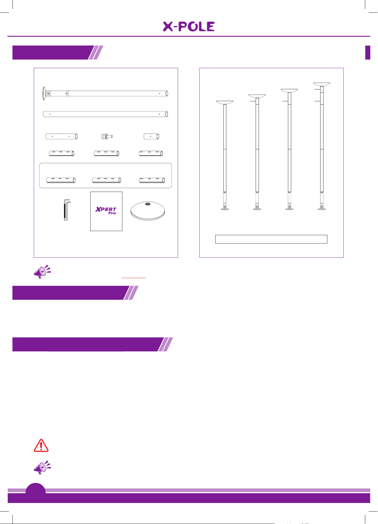
Product
Fig. (1.1) Fig. (1.2)
Box Contents
(40 & 45mm) Pole set
A-Pole (with X-Lock)
B-Pole
Extension 250mm (10”)
X-Joint 200mm (8”) X-Joint 200mm (8”) X-Joint 180mm (7”)
X-Joints supplied in 40mm Pole Sets & 45mm Silicone Pole sets
X-Joint 250mm (10”)
6mm/5mm
Hex Key
Top Insert
X-Joint 250mm (10”) X-Joint 200mm (8”)
X-POLE
LEADER IS POLE & AERIAL FITNESS
Instruction manual
Instruction Manual
Extension 125mm
Upper Dome
What you need before you start:
1x Tape Measure & 1 x Spirit Level
X-POLE XPERT Pro Height Chart
125mm
2260 - 2385mm
88.9" - 93.8"
7' 4"- 7' 9"
Standard set heights 2260 - 2755mm (88.9" - 108.4")
Sizes achievable using the 125mm & 250mm extensions
2385 - 2505mm
93.8" - 98.6"
7' 9"- 8' 2"
All measurements include an allowance to enable you to
assemble your pole as per the instruction manual
250mm 250mm
2505 - 2630mm
98.6" - 103.5"
8' 2"- 8' 7"
125mm
2630 - 2755mm
103.5" - 108.4"
8' 7"- 9'
TIP: Measurement Calculation: 100mm = 10cm = 3.94 inches (or divide the amount of millimetres
by 25.4 to get inches): ALWAYS use millimetres or inches for measurements (NOT cm & ft)
Checking the parts
Please check the contents of your XPERT Pro pole with the contents diagram (Fig 1.1). If anything is missing or damaged,
please contact your point of purchase. Please study the contents and the part descriptions in the diagram [Fig 1.1] as
these are used throughout the instruction manual and are important for installation.
X-Pole Xpert Pro height chart
Using the full (125mm/5") allowed length of the Adjuster Unit (which adjusts the height of the pole) & both included
extensions (125mm/5" & 250mm/10") will allow the XPERT Pro to fit ceilings between the ranges of 2260mm (88.9")
to 2755mm (108.4"). If you have a ceiling which is higher than 2755mm (108.4"), you will need to purchase additional/
optional extensions from our website www.xpole.com (first select your region, then search for the ‘Extensions’ section)
or from your point of purchase.
The A-Pole Adjuster Unit has the capability of extending the XPERT Pro pole by 125mm (5"). With Adjuster Unit closed
(contracted) you will be able to achieve a height of 2260mm (7'4) & with it open (extended) using both the supplied
extensions, you will achieve a height of 2755mm (9').
4
CAUTION: You should NEVER use more than 125mm (5”) of the Adjuster Unit.
TIP: Home Poles are suitable for heights up to 3390mm. For heights above this, please contact
your local X-POLE office regarding Dual-lined one-piece and multi-piece poles.
Page 5
®
LEADERS IN POLE & AERIAL FITNESS
Copyright© Vertical Leisure Ltd. 2019 Version 2.1 All rights reserved.
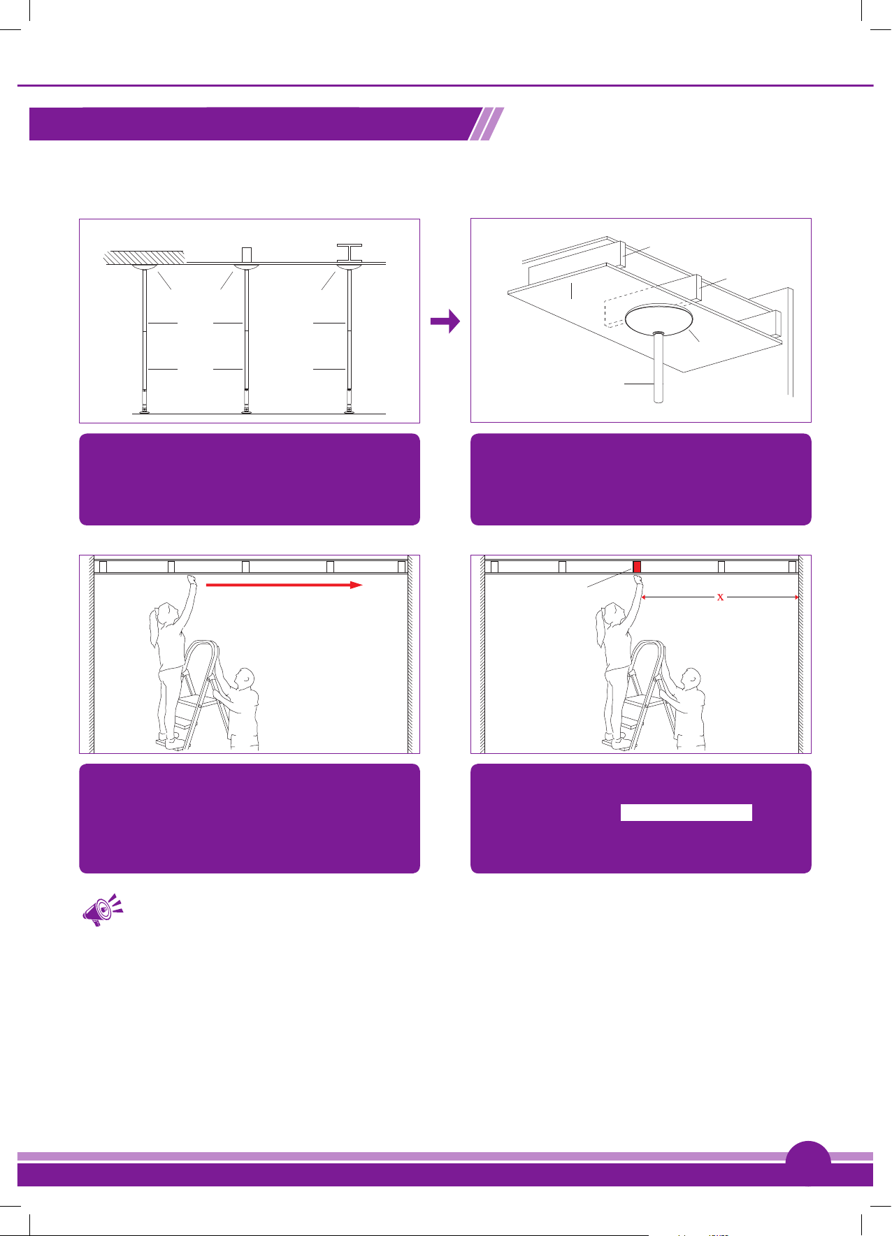
Choosing the best place for your X-Pole
Try to find a suitable area in the centre of your room, where you would like to install your pole. Above this area, you will
need to locate a ‘Joist’, please see instructions below on how to do this.
Fig. (2.1) Fig. (2.2)
Solid Ceiling Single Joist Steel Beam
Upper Dome
B-Pole
A-Pole
The XPERT Pro must be installed in the most secure
location possible, like under a solid ceiling – if you
do not have a solid ceiling, you will have to locate a
Upper Dome
B-Pole
A-Pole
Joists are beams of wood that run from wall to wall
and support your ceilings. The Upper Dome must be
centred under the Joist.
‘joist’ or ‘beam’ to install the upper dome against.
Fig. (2.3) Fig. (2.4)
Ceiling
Joist
Joist
Ceiling
Upper Dome
Pole
Joist
To find a Joist above your ceiling, tap across the
ceiling with your knuckle until a solid sound is heard
– this will be the Joist. If you keep tapping across
Once a Joist is located, take a position measurement
from the wall for future reference. Write this
measurement here: X = _________________
the ceiling the sound will become hollow – the space
between the Joints.
TIP: Joists can be located using an optional Joist/stud finder; this can be purchased from most
hardware stores.
5
Page 6

®
Copyright© Vertical Leisure Ltd. 2019 Version 2.1 All rights reserved.
Finding a suitable exercise & dance area
TIP: Measure a circle with a diameter (measured from one point of a circle across to another) of
approximately 3000 – 3500mm (120” – 138”) and locate your pole in the centre of the circle.
Fig. (3.1) Fig. (3.2)
Chair
Floor
1.5m min
Place a chair beneath the location where you have
identified your Joist OR imagine a fully assembled
pole beneath this spot.
Fig. (3.3)
Whilst rotating around the chair/imaginary pole you
must not hit or touch anything else in the room.
Fig. (3.5)
Measuring the Height of the Ceiling
Accurately measure the height of the ceiling at the point of use
and match the ceiling height to the pole height on the chart [Fig 1.2]
Fully stretch both your arms & place one hand on the
chair/imaginary pole and walk around it in a circular
motion.
Fig. (3.4)
This area will enable you to fully extend your arms &
legs when using the pole.
Ceiling
6
TIP: If longer extensions are required (than those supplied in
the standard set), then a key point is to minimise the number
of extensions & joints used for a given height requirement; i.e.
if the required extension length is 500mm – it is better to use:
Tape Measure
1 x 500mm extension & 1 x X-Joint rather than
2 x 250mm extensions & 2 x X-Joints.
Home Poles are suitable for heights up to 3390mm’s. For heights above this, please
contact your local X-POLE office regarding Dual-lined one-piece and multi-piece poles.
CAUTION: Home poles are not suitable for studio use.
Now you have found a suitable exercise area & the ideal spot for the installation of your pole.
Floor
Page 7

®
LEADERS IN POLE & AERIAL FITNESS
Copyright© Vertical Leisure Ltd. 2019 Version 2.1 All rights reserved.
EXPAND
CONTRACT
EXPAND
CONTRACT
How does X-Poles X-Joint work?
X-POLES use a revolutionary joint called the X-Joint that expands inside the pole tubes to lock them together and stops
them from coming apart/separating. To optimise the X-Joint’s key features and ensure correct operation, it is important that
you carefully follow these instructions. X-JOINT OPERATION: PLEASE NOTE: ANTI-CLOCKWISE = COUNTER CLOCKWISE
Fig. (4.1) Fig. (4.2)
180mm (7”)
EXPAND
CONTRACT
200mm (8”)
EXPAND
CONTRACT
250mm (10”)
EXPAND
CONTRACT
EXPAND
CONTRACT
EXPAND
CONTRACT
EXPAND
CONTRACT
Expansion/
Contraction Screws
EXPAND
CONTRACT
Arrow Mark
Key
180mm X-Joint
200mm - X-Joint
200mm - X-Joint
125mm
250mm
B-Pole
A-Pole
There are 3 sizes of X-Joints; 180mm (7”), 200mm
(8”) & 250mm (10”). The XPERT Pro is supplied with:
40mm: 1 x 200mm (8”) 2 x 250mm (10”)
45mm: 1 x 180mm (7”) 2 x 200mm (8”)
The 180mm (7”) X-Joint has one half longer than the
other & is marked with an arrow (on the shorter end),
when used, this must be installed at the top of the
pole with the arrow pointing upwards.
CAUTION: The 180mm X-Joint (200mm in the case of 40mm & silicone poles) should only be
used with the 125mm extension.
Fig. (4.3) Fig. (4.4)
Pole Tube
Hex Key
X-Joint
Fully Inserted
Pole Tube
X-Joint
Hex Key (6mm)
The X-Joint features a special mechanism which
expands/contracts to lock/loosen the pole tubes
together. Please test this prior to assembly.
Always remember:
TO EXPAND/TIGHTEN: Clockwise
TO CONTRACT/LOOSEN: Anti/Counter-Clockwise
TIP: Before pole installation test the operation of
the X-Joint on its own and then with 2 x Extension
Tubes. It is better to gently/ loosely tighten the
X-Joints and then undo and firmly re-tighten them
when the pole is in place, as when the pole is
vertical, the weight/pressure of the pole tubes
will push the joints tightly together.
The Joint expansion is done by FULLY inserting the
6mm Hex Key (with black plastic cover) into the pole
tube & rotating clockwise.
Fig. (4.5)
CLOCKWISE to
EXPAND/TIGHTEN
Pole Tube
ANTI/COUNTER
- CLOCKWISE to
CONTRACT/LOOSEN
Hex Key
7
Page 8

®
Copyright© Vertical Leisure Ltd. 2019 Version 2.1 All rights reserved.
EXPAND
CONTRACT
Assembling your X-Pole
Connecting the A-POLE (main tube & base) to the B-POLE.
Fig. (5.1)
X-Joint
EXPAND
Key
U Keyway Slot
EXPAND
CONTRACT
CONTRACT
Pole Tube
At the centre of the X-Joint are 2 x Keys. These Keys slide into the corresponding U Keyway slots in the pole tube.
Fig. (5.2)
U Keyway Slot
A-Pole B-Pole
Key
X-Joint
Insert a 200mm X-Joint (250mm X-Joint for 40mm
and Silicone poles) into the A-Pole ensuring the keys
locate into the U Slots and the expansion screws line
up with the holes on the pole tubes. Next attach the
B-Pole to the A-Pole with the X-Joint ensuring the
Fig. (5.3)
B-Pole
Visible Gap
No Gap
A-Pole
Check the tube edges are tight together – then gently
tighten the screw in the A-Pole – now gently tighten
the other tube (B-Pole) – continue to progressively
tighten each, alternating between the two until no
further force can be applied to the screws.
Keys engage with the U Keyway Slots.
Fig. (5.4)
Hex Key
A Pole
CLOCKWISE to TIGHTEN
Hex Key
B Pole
CAUTION: It is important to tighten the screws progressively – alternating between the screws,
tightening Clockwise. This will ensure the X-Joint pressure is equalised within the pole tubes.
Failure to do so can permanently damage your pole. Joints need tightening regularly and should
be checked each time before using the pole.
Scan QR
for full
demonstration video
on the X-Joint
8
Page 9

®
LEADERS IN POLE & AERIAL FITNESS
Copyright© Vertical Leisure Ltd. 2019 Version 2.1 All rights reserved.
Fig. (5.5)
Install Extensions at the top of the B-Pole.
A Pole
These tubes are always installed together
B Pole
X-JOINT EXTENSION
Then, as required, keep adding X-Joints and Extensions to reach your desired height – minimising the number of joints
and extensions by using optional longer extensions, available from our online shop; www.xpole.com (first select
your region, then search for ‘Extensions’) or local supplier.
Fig. (5.6)
A Pole
EXTENSION
B Pole
NEVER INSTALL EXTENSIONS IN THE MIDDLE OF THE POLE – THIS IS DANGEROUS. ALWAYS
INSTALL EXTENSIONS AT THE TOP OF THE B POLE.
TIP: If longer extensions are required (than supplied in the standard set), then a key point is
to minimise the number of extensions & Joints used for a given height requirement; i.e. if the
required extension length is 500mm – it is better to use [1 x 500mm extension & 1 x X-Joint]
rather than [2 x 250mm extensions & 2 x X-Joints].
9
Page 10

®
Copyright© Vertical Leisure Ltd. 2019 Version 2.1 All rights reserved.
Get to know your X-Pole adjustable parts
Fig. (6.1)
A-Pole
Red Alignment Line
3x Adjuster
Locking Hex
Screws
Adjuster cover
Adjuster Cover
Keyhole
X-Lock
Rubber Grip
Fig. (6.2) Fig. (6.3)
Lift X-LOCK
collar
Inserting the top insert and upper dome
Fig. (7.1)
Static
Locked
A Pole
B Pole Top Insert
Extension
Upper Dome
Once the A-Pole and B-Pole (and any additional extensions) are connected, insert the Top Insert into the
B-Pole or last extension used, then slide the upper dome onto the top insert.
BE CAREFUL WHEN YOU LIFT THE ASSEMBLED POLE, TO INSTALL, THAT THE UPPER DOME DOES NOT
FALL OFF, AS IT IS LIFTED INTO POSITION. TWO PEOPLE ARE RECOMMENDED FOR 1ST INSTALLATION
CAUTION: DO NOT FORGET: If you are using extensions, you can ONLY use a 180mm X-JOINT
(200mm in the case of 40mm & silicone poles) with a 125mm extension and make sure the
ARROW on the 180mm X-JOINT is always pointing towards the ceiling.
Installing Xpert pro
CAUTION: When assembled, the pole is heavy and at full height, NOT easy to handle. It is
therefore MANDATORY/COMPULSORY that 2 people install the pole – i.e. 2 people should lift it
into position and 1 person hold the pole while the other rotates/expands the height adjuster.
Make sure that the base of the pole is at the centre point of your dance area – as explained in ‘Finding a suitable exercise
& dance area’ [Fig 3.1- 3.4] and under the selected Joist [Fig 2.4].
10
Page 11

®
LEADERS IN POLE & AERIAL FITNESS
Copyright© Vertical Leisure Ltd. 2019 Version 2.1 All rights reserved.
Fig. (8.1) Fig. (8.2)
Ceiling
With one person holding the base, the other person
should slowly and carefully lift the pole, raising it until
it is vertical and under the Joist. DO NOT kick into
position.
Joist
3 x Adjuster Locking
Hex Screws
Adjuster Cover
ensure the X-LOCK is locked in static/non-spinning
mode by turning it clockwise (see fig 6.3). Now undo
the 3 Adjuster Locking Hex Screws at the top of the
Adjuster Cover with the 5mm Hex Key - a minimum
of 2 whole turns. DO NOT completely remove the
screws.
Fig. (8.3) Fig. (8.4)
Anti / Counter
Clockwise
Tighten / Expand
Ceiling
Tighten/Expand
ANTI/COUNTER -
CLOCKWISE to LOOSEN
Joist
X-Lock
Pole Expansion: Rotating the main pole tube from
left to the right (Anti/Counter-Clockwise) will Expand/
Tighten the Pole. Rotating the pole tube from right to
the left (Clockwise) will Shorten/Loosen the Pole.
Fig. (8.5)
Anti/Counter-Clockwise
Once vertical, with the second person still holding
the base, rotate the pole, Anti/Counter-clockwise (i.e.
rotate left to right) which will expand the pole until it
touches the ceiling.
Checking the pole is level
Once the Upper Dome is against the ceiling and
before it is tightened further, make sure that the pole
is vertical. Best way to do this is using a ‘spirit-level’
(which can be purchased from a local hardware
store) or visually align the pole with a door or window
frame.
11
Page 12

®
Copyright© Vertical Leisure Ltd. 2019 Version 2.1 All rights reserved.
Fig. (8.6) Fig. (8.7)
It is critical that the Upper Dome is flat against the
ceiling/Joist. DO NOT expand the adjuster further
until the upper dome is flat against the ceiling/Joist.
If the Upper Dome is not flat, the plate could rotate,
and slip or damage the ceiling.
Fig. (8.8) Fig. (8.9)
Damaged
Firm Pressure
Too Much Pressure
Tighten the pole until positive pressure is felt and
the pole is firmly in place. DO NOT exert too much
pressure. Rock/Shake the pole to ensure it does not
move from its position. Now change pole mode to
‘Spin’ (see fig 9.2). Spin the pole gently with your
hands, if the pole rotates smoothly, your pole has
If the pole is not vertical, move the base into the
required position. DO NOT move the Upper Dome
which must be kept over the centre of the joist at all
times. To move, undo the pole and reposition,
DO NOT KICK THE BASE INTO POSITION.
When expanding/unwinding the pole Anti/Counterclockwise, the adjuster cover will rise. If a red ‘O’
ring on the adjuster is exposed, this indicates that
the adjuster is over extended and you will require an
additional extension to use your pole which can be
purchased from our website www.xpole.com
been tightened correctly. If the pole DOES NOT
rotate smoothly, it has been OVERTIGHTENED. In
DO NOT USE AN OVEREXTENDED POLE
this instance, lock the X-Lock and loosen the pole
half-a-turn. Repeat until pole rotates smoothly.
Extended
too far
Adjuster
Cover
Adjuster
Cover
Keyhole
Red
‘O’ Ring
Vertical
Locking
Guide Line
Correct
'O' ring
covered
Fig. (8.10)
12
Adjuster Cover
Red ‘O’ Ring
Vertical Line
Adjuster
Adjuster Cover
Keyhole
CAUTION: Vertical line must be aligned
with the adjuster cover keyhole to prevent
permanent damage to your pole.
If ANY of the red ‘O’ ring is exposed, the adjuster
is at its maximum allowed length (125mm/5”). It is
now mandatory/compulsory to use the supplied
extensions or purchase an additional extension,
available from our website www.xpole.com
DO NOT extend the pole beyond the red ‘O’ ring.
Page 13

®
LEADERS IN POLE & AERIAL FITNESS
Copyright© Vertical Leisure Ltd. 2019 Version 2.1 All rights reserved.
Fig. (8.11) Fig. (8.12)
3 x Adjuster
Locking Hex
Screws
Adjuster Cover
Vertical
Line
Adjuster
Body
Once the pole is tight, rotate the pole until one of the
three Adjuster Cover Keyhole’s is in alignment with
the red vertical line on the Adjuster. This will ensure
that the pole is properly aligned. Failure to do so will
permanently damage your pole. Now tighten the 3
Adjuster Cover
Keyhole
Once the pole feels tight and does not move, try
practicing a turn with at least one foot on the floor.
Re-tighten as necessary until there is no movement.
Once you are certain that the pole has been installed
safely - try a move with your feet off the ground.
Adjuster Locking Hex Screws tightly with a 5mm Hex
Key to lock the A-Pole.
Your XPERT PRO is now ready for use.
CAUTION: Vertical RED line must be aligned with the adjuster cover keyhole to prevent damage.
TIP: If the floor is not solid (concrete), it helps, once the pole is tight, to have someone stand
on the base and then re-tighten. This compresses the floor and also makes it easier to rotate
the pole.
CAUTION: Do not over-tighten the XPERT Pro Pole - only tighten till good positive pressure
is felt and the pole is firmly in place.
Static to Spin
Fig. (9.1)
Static
Locked
Lift
X-LOCK
collar
To lock your X-LOCK and place it in to static mode,
lift the X-LOCK collar and turn it clockwise.
TIP: If the X-LOCK does not fully engage, it may be necessary to slightly rock the pole as you
twist the X-LOCK rubber grip.
Fig. (9.2)
Spinning
Unlocked
Lift
X-LOCK
collar
To unlock your X-LOCK and place it in to
spinning mode, lift the X-LOCK collar and turn it
counter/anti-clockwise.
13
Page 14

®
Copyright© Vertical Leisure Ltd. 2019 Version 2.1 All rights reserved.
Pole maintenance & removal
Fig. (10.1)
Anti/Counter-Clockwise
Tighten/Expand
Because the XPERT Pro pole uses pressure to
remain in position. The pole tightness and X-Joints
should be checked regularly during use, ideally every
30 minutes.
If there is any movement, DO NOT USE, until
you have re-tightened. Always check the
X-Joints at the same time.
Fig. (10.3)
Fig. (10.2)
Clockwise
Loosen/Shorten
3x Hex Screws
To take down the pole, ensure the X-Lock is in static/
non-spinning mode and undo the 3 x Hex Adjuster
Locking Screws (DO NOT completely remove the
screws). Then turn the pole clockwise to contract/
release the pole. Once the pole has been removed
from its position, the Upper Dome can be removed.
Hex Key
A Pole B Pole
ANTI/COUNTER - CLOCKWISE to
LOOSEN
LOOSEN
Hex Key
LOOSEN
Lay the pole tubes on the floor and undo the X-Joints to disassemble the XPERT Pro. To undo the X-Joint – turn both
Hex Screws Anti/Counter Clockwise – undo screws until there is pressure against the key.
CAUTION: Store your Xpert Pro pole only in a warm, dry place
Cleaning your pole
Fig. (11.1)
X-Clean & Micro-Fibre Cloths
X-POLE strongly recommends the use of X-CLEAN with our
specially designed Micro-Fibre Cloths to clean and maintain the
surface of your XPERT Pro Pole. You can purchase these items from
our website www.xpole.com (first select region, then search
for X-CLEAN) or your point of purchase.
14
DO NOT USE X-Clean on Brass, Powder Coated or Silicone Poles.
Page 15

®
LEADERS IN POLE & AERIAL FITNESS
Copyright© Vertical Leisure Ltd. 2019 Version 2.1 All rights reserved.
Additional Accessories
Home Mount Vaulted Ball Mount
*Designed to be discreet and minimalist, the Home Mount is the perfect way to securely
install your X-POLE with a permanent mount, minimising the visual impact of a pole
mount. Available in Powder Coat White, Chrome and Titanium Gold.
*For permanent pole installation and maximum stability & safety, the Vaulted Ball Mount
can be installed on flat or angled ceilings. Available in Chrome or Titanium Gold.
Xpert Pro Carry Case
Item No. PX-CS01
®
*The XPERT Pro Carry Case allows you to easily store your pole and take it anywhere,
along with a spare sleep for additional extensions and X-JOINT’s
Extensions
100mm
Ceiling Plate X-Clean
Ceiling
Ceiling Plate
Joist
Upper Dome
Extension
125mm
150mm
175mm
*To reach heights above 2755mm’s, we have a
large selection of extensions in 40mm & 45mm
200mm
250mm
300mm
400mm
500mm
*The ideal solution to clean and care for your X-POLE. Not
suitable for Brass, Silicone or Powder Coat poles.
diameters and all available finishes.
750mm
1000mm
Additional Assistance Section
PLEASE NOTE: ANTI-CLOCKWISE = COUNTER CLOCKWISE
(A) As damage can occur from the pressure used to keep the XPERT Pro Pole in place, it is mandatory
that the pole is centred under one joist. The better aligned the upper dome is under the centre of
the joist and the more care taken in assembly and set-up, the less potential there is for damage.
(B) Most plasterboard or plaster ceilings, will flex/compress with pressure. This means that the
retaining nails/pins/screws can be pushed out of the plasterboard when pressure is applied by
the pole adjuster. If this happens, just re-nail or re-tighten the fixing screws, fill and re-paint.
Visit us at: www.XPOLE.com
B-Pole
Item No. X-CLEAN
15
Page 16

Copyright© Vertical Leisure Ltd. 2019 Version 2.1 All rights reserved.
®
LEADERS IN POLE & AERIAL FITNESS
®
UK & EUROPE
®
®
®
®
®
Email: sales@x-pole.co.uk
Tel: +44 (0) 208 449 4400
www.x-pole.co.uk
USA
Email: info@xpoleus.com
Tel: +1 888 976 5387
www.xpoleus.com
Australia
Email: sales@x-pole.com.au
Tel: +61 (0) 2 9589 2645
www.x-pole.com.au
Korea
Email: xpolekorea@hanmail.net
Tel: +82 (0) 32 277 5882
www.xpolekorea.kr
Asia
Email: sales@x-pole.asia
Tel: +86 (21) 6236 6090
www.xpolecn.com
Email: sales@x-pole.co.nz
Tel: +64 (0) 9 528 0998
www.x-pole.co.nz
New Zealand
Warranty
This product has been manufactured and tested to the highest quality standards by X-POLE. This Limited Warranty offered by X-POLE
This warranty extends to the original purchaser only and is non-transferable. Only consumers purchasing X-POLE products from authorised X-POLE
retailers or resellers or through the X-POLE website may obtain coverage under our limited warranties.
What is covered?
X-POLE warrants this product against defects in material or workmanship as follows:
X-POLE, at its own discretion, will replace at no charge, for parts only, replace any product or part of the product that proves defective because of
improper workmanship and/or material, under normal installation, use, service and maintenance. If X-POLE is unable to provide a replacement and repair
is not practical or cannot be made in a timely fashion, X-POLE may elect to refund the purchase price in exchange for the return of the product.
How Long Does The Coverage Last?
Our warranty periods are 6 MONTHS from the documented date of purchase, depending on the type of product and where it was purchased. This does
not affect your statutory rights.
What Our Warranty Does Not Cover?
Our warranties do not cover any problem that is caused by:
A. Conditions, malfunctions or damage not resulting from defects in material or workmanship.
B. Conditions, malfunctions or damage resulting from (1) normal wear and tear, improper installation, improper maintenance, misuse, abuse, negligence,
accident or alteration.
C. Accessories, connected materials and products, or related products not manufactured by X-POLE.
D. Defects from use, wear and tear, chipped edges from pole to pole contact or being dropped and anything outside of a pure manufacturing defect are
not covered.
Due to the high specification mirror finish, small tube surface blemishes or stress lines may be visible. These do not detract away from
the quality of use of the pole and are only cosmetic issues.
POWDER COATED POLES ONLY: The Powder Coating is susceptible to damage if the pole is dropped or scratched in any way. When
installing X-Joints/adding extensions, be careful not to damage the powder coating. DO NOT USE CHEMICAL BASED CLEANERS ON
POWDER COATED POLES.
covers defects in material or workmanship in new X-POLE products for a period of 6 months.
 Loading...