

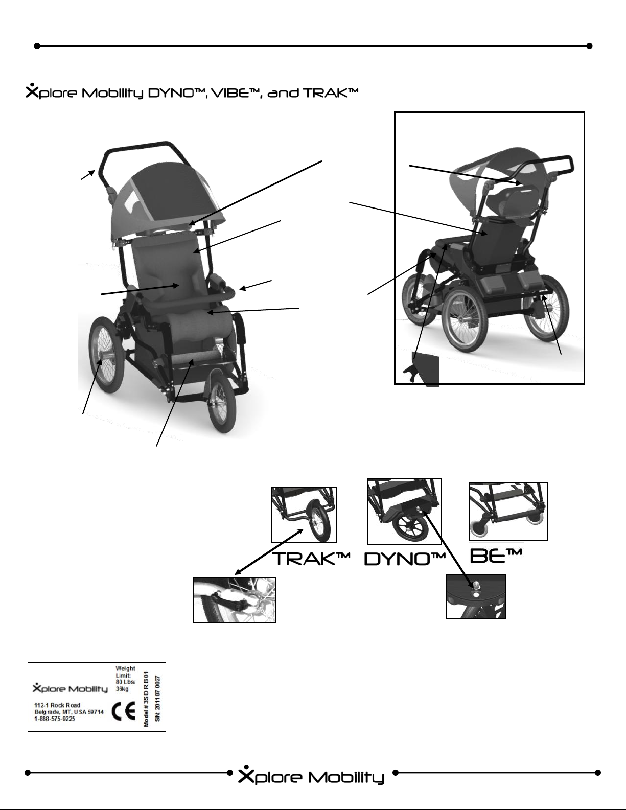
□ BE™
□ TRAK™
□ DYNO™
USER MANUAL
PATENT PENDING
CHAIR SUPPLIER: THIS MANUAL MUST BE GIVEN TO THE USER OF
THIS DEPENDENT MOBILITY BASE.
USER: READ THIS MANUAL BEFORE USING THIS DEPENDENT
MOBILITY BASE AND SAVE FOR FUTURE REFERENCE.
Product delivered may vary from the one described and pictured in this manual.
We are sorry that we can not offer this user information in a format appropriate for use by visually impaired people.
If you lose this user manual you can download it from
Doc. No: 08-009 REV 3.1
Serial #:___________________
Delivery:___________________
www.xploremobility.com
Ver. 10/2011
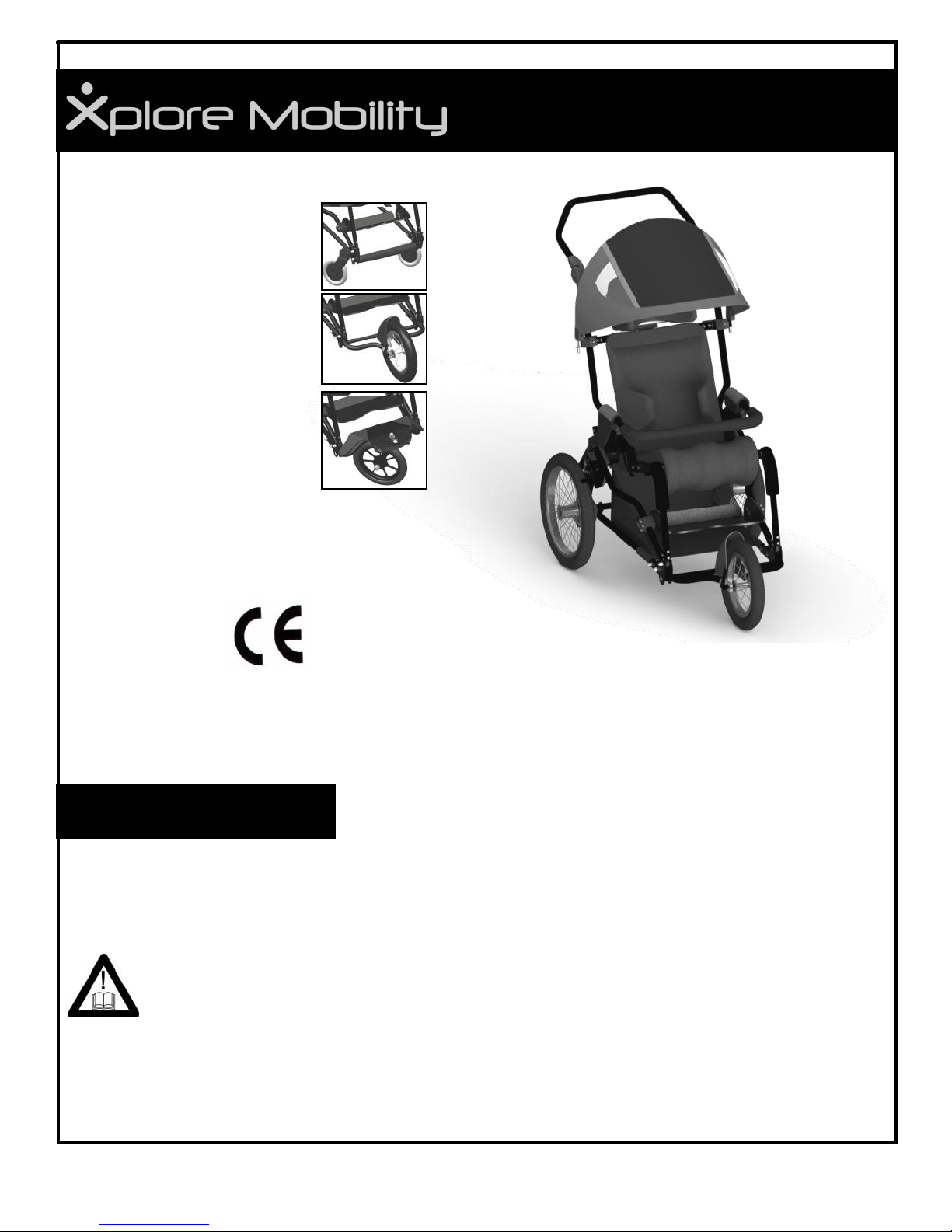
“Xplore Your World!”
You have made a great choice for your child by choosing a Xplore Mobility
Chair. We believe that every child should be able to function to the best of
their ability. We welcome questions and comments about our products
and services. Please contact us or our distributors using the information
below:
Manufacturer:
Xplore Mobility
112-1 Rock Road
Belgrade, Montana, USA , 59714
info@xploremobility.com
www.xploremobility.com
Xplore Mobility
112-1 Rock Road, Belgrade, Montana 59714,
as the producer declares that the Xplore Mobility
Wheelchair conforms to the requirements of the
93/42/EEC guidelines.
Importer:
Your Authorized Dealer is:
2

“For kids who like to move!”
TABLE OF CONTENTS
I. XPLORE MOBILITY CHAIR FEATURES AND OPTIONS ................................ 4
Introduction ...................................................................................................... 4
Intended User .................................................................................................. 4
Intended Attendant .......................................................................................... 4
Declaration of Conformity ................................................................................ 4
Terms of Warranty ........................................................................................... 4
Service & Repairs ............................................................................................ 4
Features & Options (Frame Components) ....................................................... 5
Positioning Components .................................................................................. 7
Adjustability, Specifications, & Additional Information...................................... 8
II. READ BEFORE USING .................................................................................... 9
III. GENERAL WARNINGS ................................................................................. 10
IV. UNPACKING YOUR NEW XPLORE MOBILITY CHAIR ............................... 13
V. OPERATING AND ADJUSTMENT INSTRUCTIONS ..................................... 14
A. Handle Bar Adjustment ......................................................................... 14
B. Wheel Lock Engagement ....................................................................... 14
C. Use of Tether ........................................................................................ 14
D. Folding and Unfolding ............................................................................ 15
E. Seat Belt Attachment .............................................................................. 15
F. RESPOND™ CX Seat Back Attachment ................................................ 16
G. RESPOND™ CX Seat Depth Adjustment .............................................. 16
H. RESPOND™ CX Seat Cushion Attachment .......................................... 16
I. Recline (Hip Angle) Adjustment ............................................................. 17
J. ACTIVATOR™ Dynamic Seating (optional) ........................................... 18
K. Footbed Adjustment .............................................................................. 18
L. Basic Planar Head Support (optional) ..................................................... 19
M. RESPOND™ Contoured Head Support (optional) ................................. 20
N. Therapeutic Tray (optional) .................................................................... 20
O. Grab Bar (optional) ................................................................................ 20
P. Chest Harnesses (optional) .................................................................... 21
Q. Lower Storage Bag (optional) ................................................................ 21
R. Sunshade (optional) ............................................................................... 21
S. Directional Alignment for DYNO™ Front Wheel ..................................... 22
T. RESPOND™ CX Seating (optional) ....................................................... 22
U. RESPOND™ LT Seating (optional) ........................................................ 23
V. WC-19 Bus Transit Option (Available only on the DYNO™) .................. 27
VI. LIMITED WARRANTY ................................................................................... 31
VII. MAINTENANCE ........................................................................................... 32
VIII. MAINTENANCE RECORD .......................................................................... 33
IX. REPAIR & REPLACEMENT PARTS ............................................................. 34
X. EXPECTED LIFE & RECYCLING .................................................................. 34
3

“Xplore Your World!”
I. XPLORE MOBILITY CHAIR FEATURES AND OPTIONS
1.1 Introduction
Thank you for selecting the Xplore Mobility Chair. We have designed this highly functional product to
make your life safer and easier. This manual is here to help you operate, adjust and care for your Xplore
Mobility Chair. We hope that this mobility and seating system meets your expectations. The designs, as
described are subject to technical alterations without notice. We are sorry that we can not offer this user
information in a format, appropriate for use by visually impaired people.
1.2 Intended Wheelchair User
Rehab pushchairs, pediatric positioning systems and strollers are appropriate for Wheelchair Users who
require mobility and positioning assistance.
(For Child weight and sizes and Wheelchair Specifications, see page 7, section 1.9 for details)
Individual who need such assistance can have a wide variety of diagnosis limiting their ability to have
mobility without such a system.
Assistance of mobility and positioning may be required due to:
Joint instability Joint defects
Neuromotor deficiencies Joint contractures
Limited strength (weakness) Considerable lack of cognitive function
Atypical muscle tone Other conditions preventing ambulation because of lack of motor skills
Loss of limbs
1.3 Intended Wheelchair Attendant
Wheelchair Attendants who operate the chair must be visually, mentally and physically capable of safely
and functionally operating the chair under all circumstances.
The Visually Impaired must contact authorized dealer to get information and instruction in the form of
verbal communication and step by step hands on training if necessary.
1.4 Declaration of Conformity
Xplore Mobility is the manufacturer and is solely responsible for the affirmation of the requirements of the
EN 12182 and ISO 7176-15:1996 Guidelines.
1.5 Terms of Warranty
Warranty, (see page 30) applies only when the product is used in concordance with the manufacturer’s
recommendations and for the intended purposes and specified conditions of the product.
1.6 Service and Repairs
Service and repair on the wheelchair should be carried out only by Xplore Mobility-authorized Dealer.
Should any problems arise, please contact the Dealer who supplied you the wheelchair. Authorized
Dealers only fit original Xplore Mobility spare parts.
4
1.7
“For kids who like to move!”
FEATURES AND OPTIONS
Frame Components
Adjustable Height
Handle Bar
Back Cushion
Quick
Release
Rear
Wheels
Foot bed
Sunshade
(Optional)
Adjustable Head
Rest (Optional)
Adjustable
Height Back
Frame
Grab Bar
(optional)
Adjustable Depth
Seat Frame
Wheel Configuration Options
Rear panel
of sun-
shade
removed to
show head
support
Kick Stand
(Optional)
Cam lock for tray &
grab bar adjustment
NOTE: Manufacturer recom-
mends only using pneumatic
tires on this chair. However,
solid tires may be available
for special order. Contact your
dealer with any questions
concerning your wheel chair.
Quick Release
The chair’s serial number label is located on the rear axle crossbar of the frame.
First four digits indicate year of manufacture.
Lever
- PRODUCTS ARE SUBJECT TO CHANGE -
Directional Lock
Pin
5
“Xplore Your World!”
Folding Frame
Ball lock pin for rear wheel
quick release
ACTIVATOR™ Dynamic Seating Option
RELEASE PLATFORM for
Folding Mobility Base,
CONTROL
PLATE
First
Second
SAFETY PLATE
CONTROL
KNOB
CONTROL PLATE in
Locked position
Fold by first, lifting up on safety
plate and second by pushing
down on RELEASE PLATFORM.
6
CONTROL PLATE in
Dynamic Position
“For kids who like to move!”
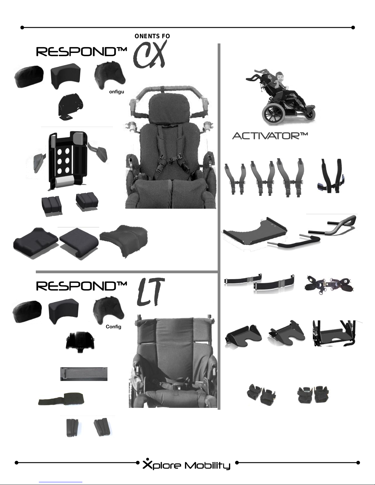
1.8 OPTIONAL POSITIONING COMPONENTS FOR XPLORE MOBILITY PRODUCTS
Planar Curved Cradle Contoured Configurable
Head Support Hardware
DYNAMIC SEATING SYSTEM
Hip Guides
Planar Curved Cradle Contoured Configurable
Head Support Hardware
Chest Harnesses Lateral Support Straps
Therapeutic Tray Grab Bars
Seat Belts
Height Adjustable
Footbed
Height / Angle
Adjustable
Footbed
Dynamic
Footbed
Torso Strap
Trunk Supports
Hip Guides
Shoe Holders
For Kids who like to move...
- PRODUCTS ARE SUBJECT TO CHANGE -
7

“Xplore Your World!”
1.9 ADJUSTABILITY, SPECIFICATIONS, & ADDITIONAL INFORMATION
ADJUSTABILITY
Seat depth
Seat width
Lower leg length
Back height
Hip angle adjustment
Chest width range
ACTIVATOR™ Option
TRAK™ DYNO™ BE™
18 to 36 cm 18 to 36 cm 18 to 36 cm
18 to 36 cm 18 to 36 cm 18 to 36 cm
20 to 38 cm 20 to 36 cm 20 to 38 cm
31 to 51 cm 31 to 51 cm 31 to 51 cm
85°, 95° 85°, 95° 85°, 95°
16.5 to 33 cm 16.5 to 33 cm 16.5 to 33 cm
TRAK™ DYNO™ BE™
Knee active range 15° 15° 15°
Seat to back active range 35° 35° 35°
SPECIFICATIONS
Max User Weight* 36 kg 36 kg 36 kg
Push handle height range
Weight/ Base & LT Seating 12.5 kg
Overall width 67 cm 67 cm 15 cm
Wheel diameter, front 31 cm
Wheel diameter, rear 41 cm
Folded dimensions /no wheels
Folded dimensions with
wheels
Reversing Width
Maximum Safe Slope
TRAK™ DYNO™ BE™
76 to 109 cm 76 to 109 cm
12 kg 14 kg
20 cm 15 cm
41 cm 41 cm
91 x 43 x 64 cm 91 x 43 x 64 cm 91 x 43 x 64 cm
107 x 43 x 64
cm
67cm 67cm 70cm
10° 10° 10°
99 x 43 x 64 cm 86 x 43 x 64 cm
76 to 109 cm
Additional Information:
If you dismantle parts of the buggy, be aware
that the heaviest part that you can remove is
the rear wheel, which weighs 0.9 kg.
All adjustments of the positioning features as
well as the folding mechanism can be done by
the parents or other operators.
All parts and accessories, which have been
made and produced by the original producer
and which can be removed without tools, can
be put on later. This procedure can be done
several times without losing functionality.
When the wheelchair is not being used, it can
be transported in a vehicle or a plane. It must
be folded and tightly fixed.
The wheelchair is not meant to be used as a
seat in a vehicle.
* User weight is defined as occupant weight plus
any items carried. Accessories and add-ons reduce maximum load proportionally.
Footbeds
Standard Short
Standard
Adjust
Dynamic
Adjustable Short
Leg Drop Angle
18-31cm 90°
18-31cm 75°,90°,105°
7– 26cm 90°
Ankle and Foot
Supports
A
B
C
A B C
X-Small
Small
Medium
8 cm 13 cm 9 cm
9 cm 15 cm 11 cm
10 cm 20 cm 13 cm
Dynamic
Chest Supports
B
A
C
A B C
X-Small
Small
Medium
17 cm 14—20 cm 11—15 cm
20 cm 16—23 cm 13—18 cm
23.5 cm 18—25 cm 15— 23 cm
8

“For kids who like to move!”
II. IMPORTANT: READ THIS BEFORE USING OUR PRODUCTS
A. READ MANUAL CAREFULLY & OFTEN
Read manual completely before use!
Familiarize yourself with handling and functions of the product before use and practice
them. You must read and fully understand the contents of this manual. Any caregiver
that is going to operate this chair should also read the manual in full.
You are responsible for the safety of your child. The safety of your child could be affected if you do not follow the instructions in this manual. Nevertheless, not all possible
circumstances and unpredictable situations can be covered by this manual. Reason,
care, and circumspection are not features of the product, they are required of persons
who use the product. If instructions are not clear and further explanation is necessary
please contact your Xplore Mobility dealer. If you do not follow all instructions and
warnings, damage to the chair or serious injury may occur.
B. DEFINITION OF SYMBOLS
WARNING!
The word “WARNING” and/or the symbol shown to the left indicate
practices that are unsafe or dangerous and could result in serious injury or death to the occupant of this chair or others.
WARNING! READ INSTRUCTION MANUAL!
!
Additional symbols are defined throughout this manual along with operating instructions.
C. CHOOSE THE RIGHT CHAIR & SAFETY OPTIONS
There are several options available to meet the needs of children. Make sure that your
(and your health care provider’s) choice of chair and other options takes into account
your child’s comfort, positioning, physical limitations, and hazards that may be encoun-
tered during daily use. Use besides the typical use can be dangerous. The pushchair is
not suitable for jogging, running, skating or similar activities. Swiveling front wheels tend
to wobble at higher speed and can cause a sudden stop and tip over of the pushchair.
Use the pushchair only at regular walking speed. Under no circumstance should you let
go of the handlebar while pushing. Do not ever push the chair away.
PAY SPECIAL ATTENTION WHEN YOU SEE THIS SYMBOL
9

“Xplore Your World!”
III. GENERAL WARNINGS
WARNING: The operator/caregiver must read and understand this manual prior to operating this equipment. If you are unable to understand any part of the manual, contact your
dealer for assistance.
WARNING: THE INITIAL SET UP OF THIS PUSHCHAIR MUST BE PERFORMED BY A QUALIFIED TECHNICIAN.
WARNING: PROCEDURES OTHER THAN THOSE DESCRIBED
IN THIS MANUAL MUST BE PERFORMED BY A QUALIFIED TECHNICIAN.
MAXIMUM WEIGHT LIMIT
The weight carried by the Xplore Mobility chair must NEVER exceed the total weight limit of 36kg
(80lbs) (Maximum occupant size plus any items carried.) When using the chair in transit, all items
including positioning tray must be removed from the chair and secured separately.
SAFETY FIRST — Reducing the risk of an accident
1. ALWAYS get properly trained and get comfortable operating the chair.
2. ALWAYS watch for obstacles and avoid them as often as possible
3. Make sure that the chair operates properly. Repair any problems before use.
CHANGES & ADJUSTMENTS
4. ALWAYS verify that the quick release clips are locked so that the back wheels don’t come
off.
5. ALWAYS secure your child in the chair with the appropriate positioning components.
1. Adjustments made to the chair will change the balance and function of the chair and may increase
risk of tip over — consult your supplier before making adjustments.
2. Warranty will be void if modifications that change the structure of the chair are made without authorization.
Avoid getting the chair wet as it may cause rust or corrosion. Dry the chair thoroughly if it is
exposed to moisture.
Extreme Temperatures: Do not leave the chair or child in the sun or near other heat sources that could
raise the surface temperatures on the chair above 41°C the chair or child outside in cold
temperatures at or below 0°C because contact with a chair in temperatures below freezing could
result in injury. Damage to the chair may also result from exposure to extreme hot or cold
temperatures.
The chair should only be used on solid gentle terrain.
Use chair as intended by the manufacturer. For instance, do not drive into obstacles
(including curbs, steps) without slowing down.
Always remove child from chair whenever lifting chair to clear major obstacles. To clear obsta-
cles such as curbs or a step, holding on to the handlebar with both hands, tilt the chair onto the
rear wheels. Pull it backwards to go up. To descend, slowly lower it forward.
10
“For kids who like to move!”
Do not go up or down stairs without the assistance of another person. If devices such as ramps or
elevators are available, please use them. If they are not available, then the chair should be carried
over the obstacle by two people with the child out of the chair. Each person should be on opposite
sides of the chair holding the bottom frame tube and the side of the handlebar.
Pay particular attention when on slopes and inclines to prevent:
• The child from falling out of the chair;
• The chair from tipping over;
• The chair from rolling away.
Before leaving the chair and before getting into and out of it, always engage the wheel locks.
Do not stand on the footplate when getting into or out of the chair.
LIFTING: Only lift the chair by parts that are solidly attached. The chair should be lifted by the
side frame members whenever possible. If folded, hold the chair by the lower side frame tubes.
If the shell is in the frame, do not tip the unit to the side or upside down because the shell could
release from the frame and cause injury. Always use two people to prevent injury and damage
to the chair.
When your child reaches for objects in front, to the side, or behind the chair, be sure that they do
no lean out of the chair too far since the shift in the center of gravity might cause the chair to tilt or
tip over.
The handling of the chair is influenced by tire pressure. Correctly inflated tires considerably improve its maneuverability. The air pressure should be at least 1.4 KPa
Please keep packaging material away from children. Plastic
packaging presents the danger of suffocation.
Never leave your child unattended in the chair even when they are
strapped in and the wheel locks are engaged.
Engage wheel locks before
transferring the child to or
from the chair!
The chair is only intended to carry one child at a time. Do not carry more than one child at a time.
Whenever you change a setting on the chair, make sure that you firmly tighten any screws that
have been loosened.
Static stability limit of chair is 10° inclination. Chair may tip over if used on inclines greater
than this.
MOTOR VEHICLE SAFETY
Do not use it as a wheelchair in a motor vehicle. Transfer the child from the chair to an approved
motor vehicle seat. When loaded into a motor vehicle always ensure that the Xplore Mobility chair
is properly secured.
11

“Xplore Your World!”
GENERAL TORQUE AND FASTENER GUIDELINES
Many of the fasteners used to construct the Xplore Mobility chair consist of a bolt with a
nut that contains a nylon coated thread (commonly referred to as “nyloc” nuts). These
connection and pivot points should be maintained and secured with the appropriate fasteners and hand tightened to eliminate a loose fit. In the case of a fastener that dictates a
pivot point, make the allowance to allow a pivoting motion, when in the unlikely situation
that these fasteners become loose, please first insure that the nut and bolt are in good
condition. If not in good condition, ascertain the cause and determine whether it can be
replaced with the equivalent new fastener. To ensure adequate grip of the nyloc nut,
make sure to tighten bolt until at least one full thread is protruding from nut. If a nut loosens that does not have a nylon insert place a couple of drops of thread locker such as
Red Loctite on the tip of the bolt before inserting bolt into nut. If there is any doubt that
the item is not repaired and made to last, please contact the authorized dealer to confirm
that the chair is to be returned and repaired.
WARNING:
When folding wheelchair, be aware that there is a risk of injury through fingers becoming
crushed or trapped.
For expected service life of the wheel chair, see chapter VII: Maintenance.
NEVER use this chair on an escalator because the chair may tip over.
To recycle wheel chair, contact your dealer for information. They may know what is best to
do for your region.
WARNING:
Child must be securely fastened to chair at all times.
If tire loses air pressure or is flat, please ask your dealer for repair.
MAINTENANCE
The chair must be inspected and maintained per the chair in section VII\III: Maintenance. Prob-
lems detected must be repaired before the chair is used.
WARNING: Contact your health care professional before using this unit with a child.
Warning: Always inspect your chair before placing your child into it. Look for loose
parts, sharp edges, hot surfaces, detached harnesses, mechanisms that are not
12
fully engaged, and any other hazards. Always engage the wheel locks before
performing a transfer of the child to or from the chair. Read this instruction
manual before using this chair.

“For kids who like to move!”
IV. UNPACKING YOUR NEW XPLORE MOBILITY CHAIR
THE ORIGINAL PACKAGE CONTAINS THE
FOLLOWING COMPONENTS:
Xplore Mobility Chair
Additional options and accessories as
ordered.
PREPARING THE CHAIR FOR USE:
1. Remove the chair & components from the box.
A. Keep Box Upright
B. Verify that package is in good shape and that no
damage has occurred during shipping.
C. Remove the Xplore Mobility Chair and accessories
from the packaging material.
D. Check to make sure that your order is complete.
2. Install the rear wheels. (If necessary) See Figure A.
A. Make sure the wheel lock lever is released.
B. Align the wheel with the axle on the chair.
3. Unfold the frame and seat back into the upright
position—see section V. D of Instruction Manual for
detailed instructions.
4. Make additional adjustments to the chair as
necessary. Refer to the appropriate
section of this manual for instructions.
5. Please refer to section V. Operating Instructions for
installation of sunshade (V.Q), seat cushion (V.G)
and seat back cushion (V.F).
Figure A
Push ball lock pin and insert into rear axle.
Lock button NOT engaged
Please see the next page of this manual.
Lock button engaged
13

Tools Required:
5/32” Hex Wrench
1/8” Hex Wrenches
7/16” Nut Driver or Open End Wrench
3/8” Nut Driver or Open End Wrench
“Xplore Your World!”
V. OPERATING AND ADJUSTMENT INSTRUCTIONS
A. HANDLEBAR ANGLE ADJUSTMENT
1. Press the buttons on the black ratchets simultaneously on
both sides of the handlebar. (fig. 1)
2. While holding the buttons down, pivot the handlebar to the
desired position.
3. Release the buttons on the black ratchet.
Figure 1: Handlebar Angle
Adjustment
A. Lock
ON
Figure 2: Wheel Lock
A. Lock ON
Figure 3: Wheel Lock
(with Kick Stand)
B. Lock
OFF
B. Lock
OFF
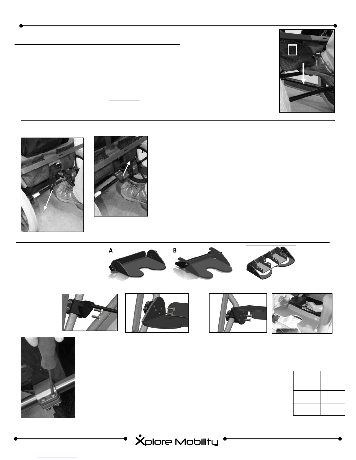
B. WHEEL LOCK (BRAKE) ENGAGEMENT
1. To lock the wheels, pull the wheel lock lever upwards (fig. 2A ).
2. To disengage the wheel lock, push the wheel lock downwards
USING KICK STAND (When the kick stand is attached.)
1. To lock the wheels, pull the kick stand upwards with your toe, or by hand
(fig.3A ).
2. To disengage the wheel lock, push the kick stand downwards with your toe
(fig. 3B). This can also be done by hand.
Warning: Do not put excessive stress on the handlebar.
Warning: Be sure to engage both the left and right
wheel locks to maintain stability.
C. USE OF TETHER (available only on TRAK™ Models)
Figure 4
Figure 5
B
A
1. Pass the tether between handle bar
and seat back (fig. 4)
2. Insert wrist through loop in tether, and
grasp the tether (fig. 5)
3. To engage brake with tether, pull
tether towards you (fig. 6, A) This engages the brakes (fig 6, B) Keep the
tether located over the top of and near
the center of the handle bar.
14
Figure 6
Warning: Keep hand in tether
strap at all times to maintain control.
“For kids who like to move!”
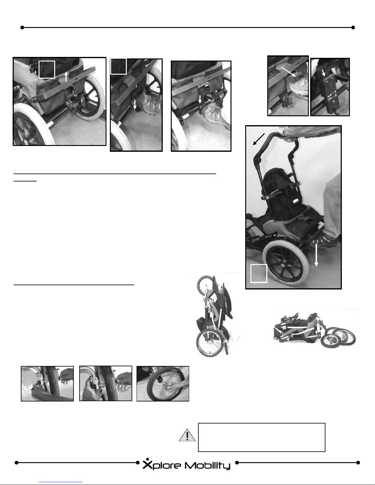
D. FOLDING WHEELCHAIR & KICKSTAND USE
1
Figure 7 Figure 8a
FOLDING THE WHEEL CHAIR (equipped with ACTIVATOR™ Dynamic
option):
1. Lift kickstand (if equipped) until brakes are fully engaged. If kickstand is
not equipped, engage each brake separately by lifting handle until brake
engages.
2. Engage chair into Active mode by using foot to push down on the Control
Knob until it “clicks”.
3. Place hand on handle bar (do NOT push bar forward or attempt to fold
yet). Slide foot up under safety flap and push down on ledge with foot.
While maintaining downward pressure on ledge, push handle bar forward
until chair folds.
2
“click”
Figure 8b
“safety flap”
“ledge”
Figure 9b Figure 9a
FOLDING THE WHEEL CHAIR (standard):
1. Lift kickstand (if equipped) until brakes are fully engaged. If kickstand is not equipped, engage each brake
separately by lifting handle until brake engages.
2. Place hand on handle bar (do NOT push bar forward or
attempt to fold yet). Place foot on Recline Adjust Bar
and push down on bar with foot. While maintaining
downward pressure on bar, push handle bar forward
until chair folds.
Figure 13
Front Wheel Quick Release (TRAK™ only)
1. Disengage tab on quick release (fig 13).
2. Loosen nut while holding tab until wheel can
be removed.
Figure 14 Figure 15
3
Figure 10
Figure 11
Using Kick Stand (note: Kick Stand not included
with RESPOND LT seating)
1. Engage brake by lifting kick stand bar, then fold
chair while leaving brake engaged.
2. Lift up front end of chair until it rests on back wheels
and kick stand. (fig. 11)
Always make sure front wheel is firmly
and securely tightened into place before
using wheelchair.
Figure 12
15

“Xplore Your World!”
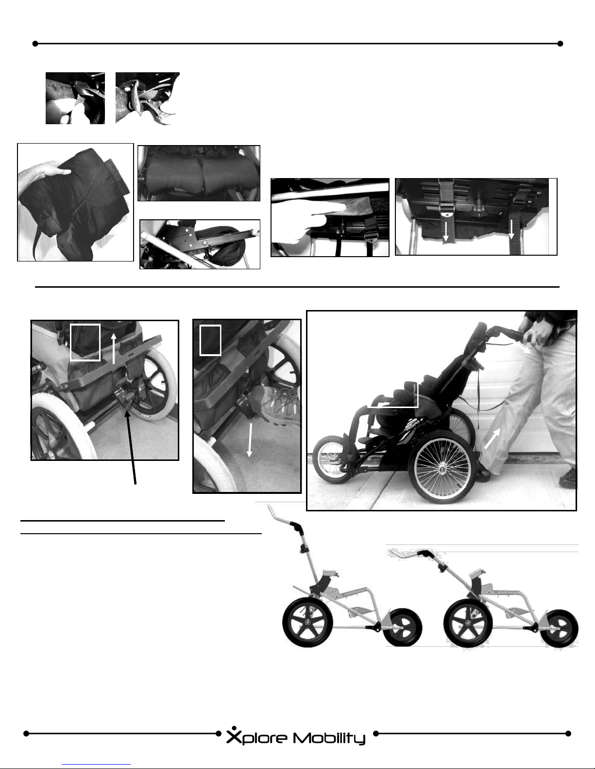
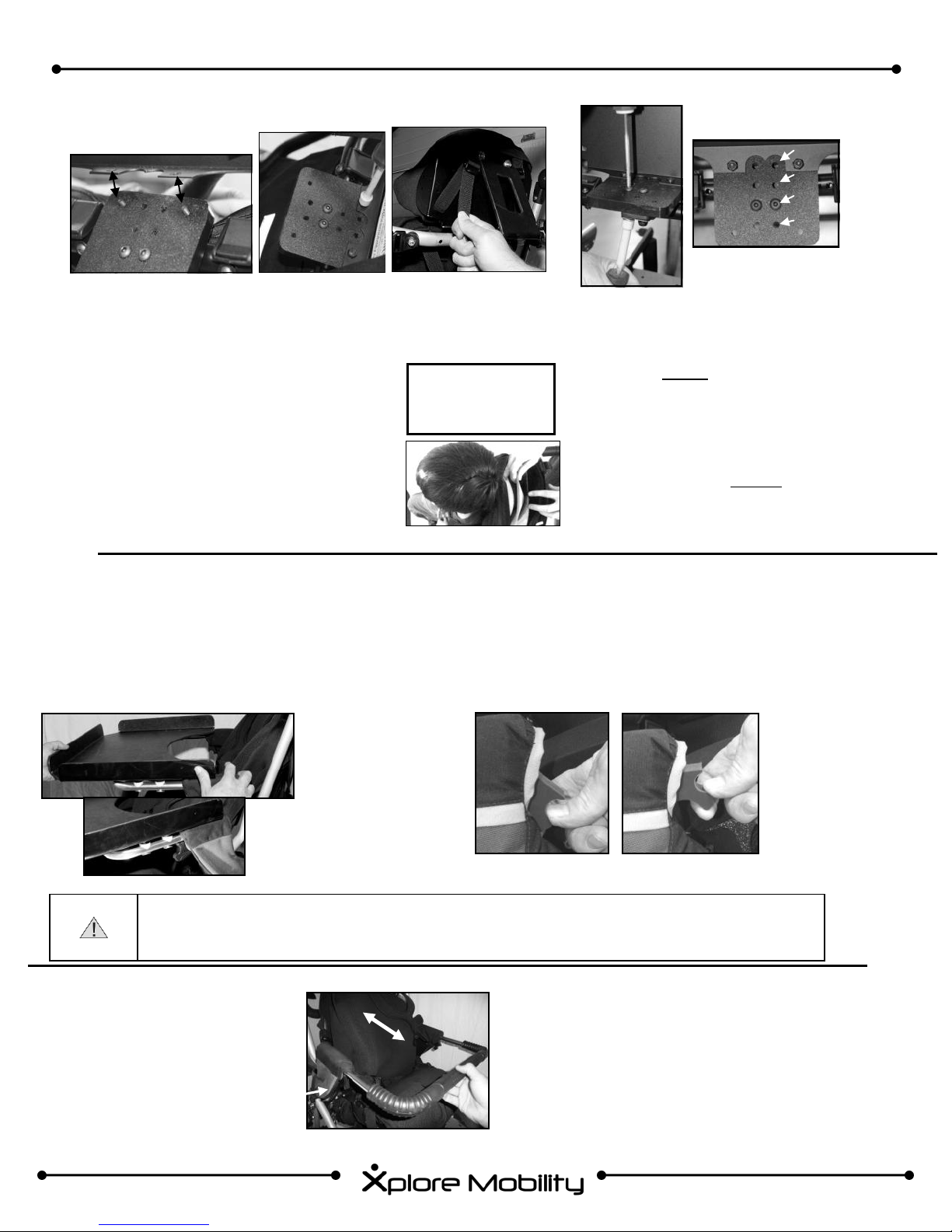
E. SEAT BELT ATTACHMENT (2 & 4 Point)
Additional
position for
4 point belt.
2 Point attachment location
Figure 16
Please note where left and right side attachment points
are for 2 pt., 4 pt. and trunk support
Figure 17
WARNING: Positioning belts should never be used for securement in motor vehicles. The chair does not ship equipped with a WD-19 compliant belt. An additional WC-19 compliant automotive type seat belt is required when the chair is
used in vehicles.
F. RESPOND™ CX SEAT BACK ATTACHMENT
Always make sure that a properly attached
seat belt is secured on the child at all times.
Chest Harness Strap
Seat Belt
Figure 18
1. To attach seat
belt, insert provided
bolt through
washer, seat belt,
and chair as indicated in (fig 18).
Tighten securely.
Figure 19
1. Align bolt to holes in seat back plate, seat
back fabric and cross tube (fig. 20).
2. Push bolt through, then thread nut onto bolt on
other side of the cross tube (fig. 21). Tighten
screw.
3. Repeat steps 1 and 2 for second mounting
point on seat back.
Figure 20
G. RESPOND CX SEAT DEPTH ADJUSTMENT
1. Look under the seat bottom and
locate the knob (figure 23).
Loosen the knob and loosen the
tensioning straps. (see fig. 32).
2. Reposition the seat base to the
desired seat depth and retighten
the knob first and the tensioning
straps second. See Section H.
below for reference to seat
cushion attachment.
Figure 23
Figure 21
NOTE: It is easier to attach RESPOND™ seat
back if headrest is rotated out of the way. See
section V.L for directions on how to do this.
Figure 24
Figure 25
Figure 22
Figure 26
16
“For kids who like to move!”
H. RESPOND CX SEAT CUSHION ATTACHMENT
Figure 27 A
Bottom
Figure 28
Figure 27 B
Front
Figure 29
Side
Figure 30
Back
I. HIP ANGLE ADJUSTMENT (RECLINE)
Attach Seat Cushion to seat plate:
1. Attach the loop strip on the rear of the seat
cushion to the hook tab on the back and seat
cushion, (fig. 31).
2. Thread the 1” webbing through the 3-Bar
Slide and leave loose, until proper seat depth
is determined. (fig. 32) Pull tight. (fig 32).
Please see G. for Seat Depth Adjustment.
Underneath Rear
Pull To Tighten
Figure 31
Figure 32
2
1
Figure 34
Figure 33
1
1
CONTROL KNOB
ADJUSTING THE HIP ANGLE (RECLINE)
(equipped with ACTIVATOR™ Dynamic option):
1. Lift kickstand (if equipped) until brakes are fully engaged. If kickstand is not equipped, engage each
brake separately by lifting handle until brake engages.
2. Push down on the control knob with foot until it rests
on the rear axle.
3. While keeping control knob resting on rear axle, grab
handle bar and pull seat back as far as it will go, then
release control knob with foot to lock seat into recline
position.
4. To release from recline and return to upright position,
repeat steps 1 and 2, then push handle bar forward to
upright position.
3
Figure 35
Hip Angle Positions
NOTE: See next page for instructions on Hip
Angle adjustment for standard chairs (not
equipped with the Dynamic option.
17
“Xplore Your World!”
ADJUSTING THE BACK ANGLE (RECLINE) (standard):
1. Lift kickstand (if equipped) until brakes are fully engaged. If kickstand is not equipped, engage
each brake separately by lifting handle until brake engages.
2. Push down with foot on the Recline Adjust bar (fig. 36), use handle bar to pull seat back in to
recline position (fig. 35), then release Recline Adjust bar so it locks seat into recline position.
3. To release from recline and return to upright position, repeat steps 1 and 2, except push seat
back forward to upright position. WARNING: WHEN RETURNING CHILD TO UPRIGHT POSI-
TION, BE CAREFUL NOT TO PUSH SEAT BACK TOO FAR FORWARD SO AS TO FOLD
CHILD IN CHAIR.
J. ACTIVATOR™ Dynamic Seating (Optional)
1. To Unlock Dynamic Option, Verify that the wheel
locks are engaged.. While supporting the child’s
weight by keeping your upper hand on handle bar,
push down on the control knob with your foot until it
“clicks” into place. (fig. 37)
2. To lock the chair into static position, release the
lever by pulling it up with your foot. (fig. 38)
2
Figure 36
“CLICK”
Figure 37
K. FOOTBED ADJUSTMENT
Footbed
Choices
Figure 39
Figure 40
FOOTBED ATTACHMENT & ADJUSTMENT
Figure 44
Figure 38
Knob has been pushed up to
the static (locked) position.
A B
Standard Angle Adjustable Dynamic
Figure 41
Figure 42
C
1. Insert provided screws through footbed (standard footbeds,
fig. 41), or through bracket (adjustable footbeds, fig. 40).
The Standard footbed can also be installed inverted by inserting screws through positions as shown in figure 42.
2. To adjust height of footbed, loosen each screw on both
sides of the footbed as shown in figure 44, then position
footbed as desired. Tighten screws.
3. To adjust angle of adjustable footbeds, pull tab (fig. 43), position footbed, and release tab so that rod rests in one of
three slots provided.
Standard
Dynamic
Figure 43
Angle Adjustment
Leg Drop Angle
7– 14in. 90°
Adjust
7- 14 in. 75°,90°,105°
7- 12 in. 90°
18

“For kids who like to move!”
K. FOOTBED ADJUSTMENT (continued)
Figure 47.1
Figure 45
Figure 46
DYNAMIC FOOTBED ADJUSTMENT
1. To adjust height of Dynamic footbed, loosen screw on limiting collar
as shown in figure 45 using a 3/16in hex wrench, then slide the limiting collar up or down as desired (fig. 46). Re-tighten the screw.
2. To swap position of the shoe holder, unscrew both bolts in the bottom
of the shoe holder (fig. 47.1). Remove, shoe holder, and align screws
to either position 1 or position 2, (fig. 47.2) then tighten bolts until the
head of the bolt is flush with the surface of the shoe holder (fig. 47.1)
Position 1
Dynamic Footbed
Position 2
Figure 47.2
L. BASIC PLANAR HEAD SUPPORT
To attach the Basic Planar Head Support:
1. Wrap the end of head support that has hook and
loop fastener around a seat back tube and fasten
the hook and loop together (fig. 48.1)
2. Clip buckles together as shown in figure 48.2.
3. Tighten webbing as desired as shown in figure
48.3.
NOTE: by tightening or loosening either strap, one can
achieve varying levels of stiffness or “cradling” as de-
sired.
Figure 48.2
Figure 48.1
Figure 48.3
19
“Xplore Your World!”
L. RESPOND™ CONTOURED HEAD SUPPORT (optional)
A B
Figure 49
Attachment
1. 1. Insert screws through plastic mounting
bracket and metal head rest plate (fig.
49A). Using 1/8in Hex Wrench and 3/8in
Nut Driver, tighten nyloc nuts onto
screws (fig 49B)
2. 2. Thread webbing through 3-bar slide as
shown in Figure 50, then tighten until
head rest is tight against metal plate.
M. THERAPEUTIC TRAY (optional)
Tray Installation and Removal:
1. Align the two tray posts with the tray receivers on the chair and push the tray posts into the
receivers to the proper position (fig 52 A).
2. Pull the cam locks on both sides up until they lock into position (fig 53 B).
3. Remove the tray by releasing the cam locks and pulling the tray out of the receiver.
Figure 50
NOTE: See section
V. S for Head Support configuration.
A
B
Figure 51
Adjustment
1. 1. To adjust the head rest rotationally
use a 5/32” Hex Wrench and 7/16” Nut
Driver to loosen screws as shown in
figure 51. Position head rest as desired, and tighten screws so that head
rest doesn’t move.
2. 2. To adjust fore/aft position of the
headrest, use a 5/32” Hex Wrench and
7/16” Nut Driver to remove screws as
shown in figure 51. Position headrest
as desired, re-insert screws into new
holes and tighten.
1
2
3
4
A
B
Warning: Tray must not be loaded with objects heavier than 11 lbs (5 kg).
N. GRAB BAR (optional)
20
Warning: Tray must be removed from chair during transport in a motor vehicle.
Cam Locks
Figure 52
Figure 53
Figure 54
A B
Cam Lock Closed Cam Lock Open
1. Align grab bar with slots in arm rest
(fig. 54), then insert grab bar into slot.
2. Use cam locks to lock grab bar into
place (fig. 53 B)
3. To remove, unlock cam locks (fig. 53
A), then remove grab bar.
“For kids who like to move!”
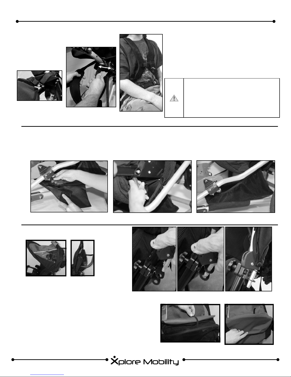
O. CHEST HARNESSES (optional)
Figure 55
Figure 56
P. LOWER STORAGE BAG (optional)
1. Wrap around bottom frame of chair (fig. 58) and attach hook/loop.
2. Insert screw through fabric and seat bottom as shown (fig. 59) and secure
with provided nut.
Figure 57
1. Insert provided bolt through washer, chest
harness, and chair and secure with nut (fig.
56)
2. Pass webbing over cross bar and then back
through cam-clamp. Close cam-clamp to
secure webbing.
3. To adjust width, un-bolt cam-clamp from
cross bar, position as desired, and re-bolt
cam-clamp to cross bar.
Warning: Chest Harness can restrict breathing if not correctly
attached! Make sure there is ample room for breathing and that
the harness is attached securely
to maintain respiration.
Figure 58
Q. SUNSHADE (optional)
1. Insert metal rod thru first receiver as
shown in Figure 61A, then insert metal
rod thru second receiver as shown in Figure 61B. Repeat on other side of chair.
2. Drape back fabric behind headrest between chair and handle bar. (Fig. 61C)
3. To cover back window, un-stick top strap
(Fig. 62A), and drape fabric over window
(Fig. 62B)
Figure 59
A B C
Figure 61
A B
Figure 62
Figure 60
21
“Xplore Your World!”
R. DIRECTIONAL ALIGNMENT FOR DYNO™ FRONT WHEEL
1. The directional alignment feature allows the
front wheel to swivel freely when needing maneuverability, as well as to lock it into position
to allow it to track optimally when outside and
going at a higher speed
2. Figure 63 A shows the wheel in the swiveling
mode. To lock it into directional mode, lift and
pivot knob until it seeds into the lower position, (fig. 63 B) Note that wheel is in forward
facing position when locked (fig 63 C)
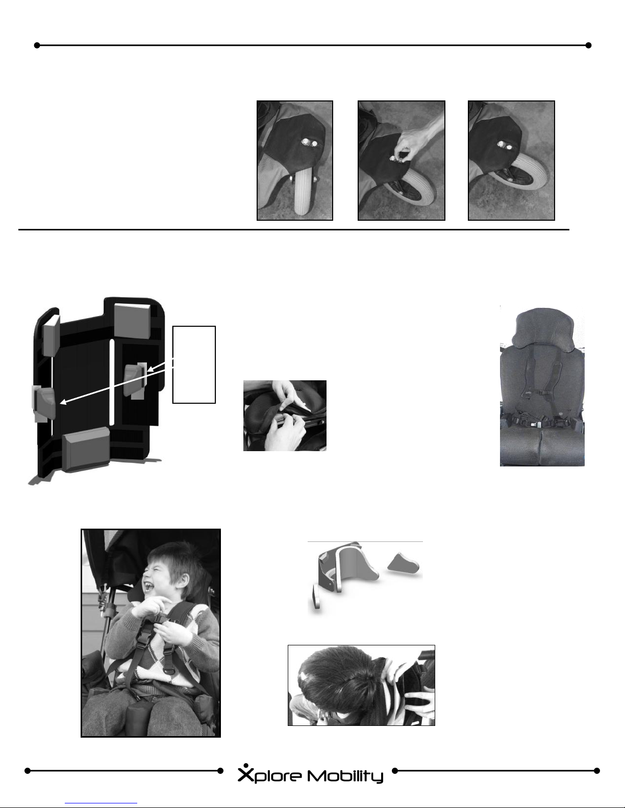
S. RESPOND™ CX SEATING (optional)
RESPOND™ Seating System is modeled directly on
the child and transferred to the Chair for a perfect fit!
Figure 64
A
(fig. 66)
Figure 63
C
B
Optional
Trunk
Supports
provide
extra
support
when
needed.
A Contouring Kit is included with every RESPOND™ Contoured-
Configurable Head Support, as well as every RESPOND™ CX
Seat Cushion and Back Cushion.
Figure 65
1. The positioning wedges on the
RESPOND™ CX Seat Cush-
ion can be moved to provide
optimum support. (see fig.64 )
2. The wedges can be easily
accessed and adjusted by
opening the dual zippers,
which are located on both
sides of the seat cushion. (see
fig. 65)
Figure 67
CONTOURED
CONFIGURABLE
HEAD SUPPORT:
A
Inserting Pads
1. Remove head rest from
metal plate (fig 67B).
2. Use zipper to open
headrest cover.
3. Add,/adjust padding as
B
desired. Zip closed. Re
-attach head rest to
metal plate.
Figure 66
22

T. RESPOND™ LT
“For kids who like to move!”
RESPOND™ LT SEAT BACK HEIGHT ADJUSTMENT
1. To adjust the height of the RESPOND™ LT seat back, use a
5/32” hex wrench to loosen the bolt as shown in figure 68.1.
Repeat on other side of the chair.
2. Adjust height of seat back as necessary and re-tighten the previously loosened bolts.
FIGURE 68.1 (optional RESPOND™ ContouredConfigurable headrest shown)
RESPOND™ LT SEAT BOTTOM ADJUSTMENT
SEAT DEPTH ADJUSTMENT
1. To adjust the seat depth, loosen bolts (one on each side of
chair) connecting seat depth tube to frame as shown in figure
68.2
2. Reposition seat depth tube into any of three positions shown
(A, B, or C), reinsert bolts and tighten.
3. Tighten seat depth straps (figure 68.3)
2. Adjust
Height
1. Loosen
Bolts
A
Figure 68.3
ISCHIAL LEDGE ADJUSTMENT
1. To adjust the position of the ischial ledge tube, loosen bolts
(one on each side of chair) connecting ischial ledge tube to
frame as shown in figure 68.4.
2. Reposition seat depth tube into any of three positions shown
(A, B, or C), reinsert bolts and tighten.
B
Seat Depth
Straps
C
Figure 68.2 (shown without ischial ledge tube)
C
Fig. 68.4
A
B
23

“Xplore Your World!”
SEAT FIRMNESS ADJUSTMENT
1. To adjust the stiffness of the seat, undo the hook and
loop fastener on the seat bottom as shown in figure 68.5.
2. To make the seat more firm, pull the tab towards you and
re-fasten the hook and loop. To make the seat less firm,
push the tab away from you and re-fasten the hook and
loop.
RESPOND™ LT HIP GUIDE ADJUSTMENT
All RESPOND™ LT Hip Guide pads (figure 68.7) are re-
movable and adjustable by way of hook and loop fasteners as illustrated in figure 68.6.
FIGURE 68.6
SOFT
FIGURE 68.5
FIRM
RESPOND™ LT HEADREST HARDWARE ADJUSTMENT
1. Using a 5/32” hex screw driver, and a 7/16” nut driver,
remove the bolts as shown in figure 68.9.
2. Using a 1/8” hex screw driver, and a 3/8” nut driver, re-
move the bolts as shown in figure 68.8.
3. Undo lateral head rest straps (shown in figure 68.8) and
remove head rest plate.
4. Replace plate on other side of tube clamp, and reassemble.
LAT. STRAPS
FIGURE 68.8
ROTATIONAL / LATERAL ADJUSTMENT
1. Loosen (but do not remove) bolts as shown in figure 68.9.
Also, loosen (but do not remove) lateral straps shown in
figure 68.8.
2. Position head rest into as desired.
3. Re-tighten bolts and reattach lateral straps.
Hip Guides
FIGURE 68.7 Hip guides shown on
RESPOND™ LT Seating
TUBE CLAMP
24
FIGURE 68.9
“For kids who like to move!”
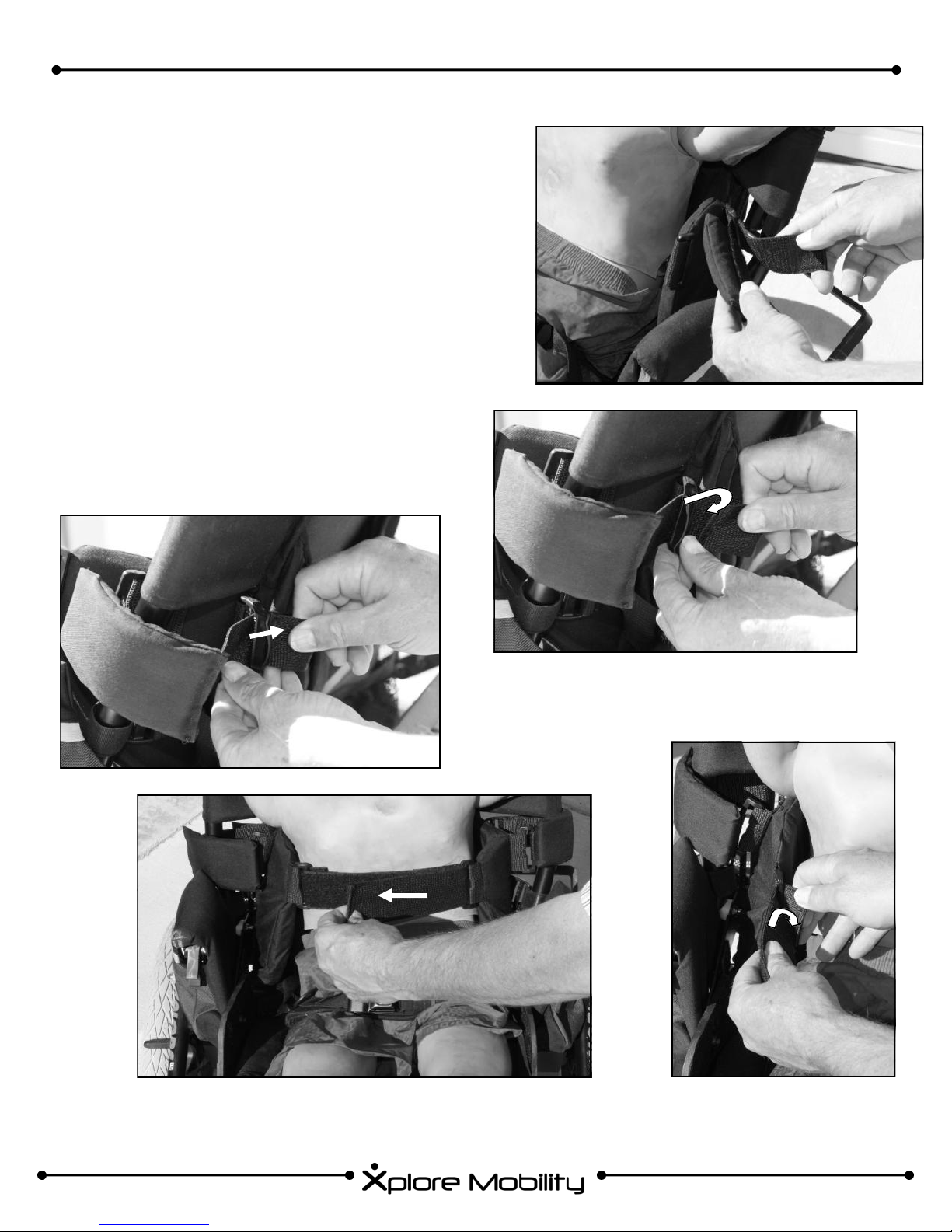
RESPOND™ LT TRUNK SUPPORT INSTALLATION & ADJUSTMENT
1. Take the long webbing end of a trunk support side
strap, thread it through adjustment ring on seat
back fabric (figure 69.1). Attach with hook and loop
to back of pad.
2. Thread short webbing around seat back tube,
through three-three bar slide (figure 69.2), back
through three bar slide (figure 69.3) and attach to
itself via hook and loop.
3. Repeat on other side of chair.
4. Loop short end of cross strap through adjustment
ring on trunk support flap. Attach it to itself via hook
and loop fastener (figure 69.5) When in use, take
webbing and pass it across child’s chest through
adjustment ring on other trunk support flap. Adjust
to desired position, and fasten cross strap to itself
via hook and loop fastener. (figure 69.4)
FIGURE 69.1
FIGURE 69.2
FIGURE 69.4
FIGURE 69.3
FIGURE 69.5
25

“Xplore Your World!”
RESPOND™ LT CROSS-OVER HARNESS INSTALLATION
To attach Respond™ LT Cross-Over harness:
1. Insert hook and loop fastener through plastic loop as shown in figure 70.1, then fasten around plastic
loop.
2. Pull harness across chair (figure 70.2) then insert buckle into receiver on cross support near the shoulder.
3. Pull on webbing tab to tighten (figure 70.3) Repeat for other side.
Fig. 70.2 Fig. 70.3
Fig. 70.1
To adjust Respond™ LT Cross-Over harness:
1. Remove buckle from webbing on harness
2. Pass webbing through desired fabric loop to (figure 70.4) to adjust
length.
3. Reattach buckle to webbing on harness. Continue with normal use.
RESPOND™ LT LUMBAR SUPPORT & LOWER THORACIC SUPPORT
Attach Lower Thoracic or Lumbar Support with provided hook and
loop fasteners in the locations as shown in figures 71.1 and 71.2.
Figure 71.1: Lumbar Support Figure 71.2: Lower Thoracic Support
Fig. 70.4
26

“For kids who like to move!”
U. WC-19 BUS TRANSIT OPTION (Available only on the DYNO™ with RESPOND CX SEATING)
ATTENTION! AT THE TIME OF
PUBLICATION OF THIS MANUAL,
THE TRAK™ AND BE™ CON-
FIGURATIONS OF THE XPLORE
MOBILITY WHEELCHAIR HAVE
NOT BEEN DYNAMICALLY
TESTED AND DO NOT CONFORM TO THE REQUIREMENTS
OF ANSI/RESNA WC/Vol1.Section 19.
ATTENTION:
We recommend that whenever possible, wheelchair users be transferred to the seats installed in a motor vehicle
and use the corresponding vehicle-installed restraint system when feasible.
The DYNO™ wheelchair conforms with the requirements of ANSI/RESNA WC/Vol 1.—Section 19 (a.k.a. WC-19)
The DYNO™ wheelchair has been dynamically tested to the procedures of Annex A with a wheelchair-anchored
belt restraint.
A wheelchair-anchored belt restraint is provided to the user when the Bus Transit option is ordered. This belt re-
straint conforms with sections 4.9.2 through 4.9.5, and 5.2 of the WC-19 and has been dynamically tested to the
procedures of Annex A.
WARNING! DO NOT USE ANY BELT RESTRAINT OTHER THAN THE ONE PROVIDED WITH THE Bus Transit
option. DOING SO SIGNIFICANTLY INCREASES THE CHANCES OF SERIOUS INJURY OR EVEN DEATH.
Wheelchair securement points are located both in
the front (fig. 72.1) and rear (fig. 72.2) of the wheelchair (only if the Bus Transit option is included with
your wheelchair). All securement points will have
symbols similar to figure 72.3 on them.
Range of User Sizes:
ADJUSTABILITY DYNO™
Seat Depth 18-36cm
Seat Width 18-36cm
Front Securement Points
Fig. 72.1
Rear Securement Points
Fig 72.2
Lower Leg Length 20-36cm
Back Height 31-51cm
Chest Width Range 16.5-33cm
Weight 14-36kg
ATTENTION: A head support
is required for use with WC-
19 Bus Transit Option
Fig 72.3
27

“Xplore Your World!”
The belt restraint included in the Bus Transit option and a four-point wheelchair tiedown system in compliance
with SAE J2249 Wheelchair Tiedown and Occupant Restraint Systems for Use in Motor Vehicles should be used
at all times during transit.
The lap belt restraint anchor-points are con-
veniently located near the junction of the
seat back and seat bottom (fig. 73).
The pelvic belt should be worn low across
the front of the pelvis, so that angle of the
pelvic belt is within the preferred zone of 45°
to 75° to the horizontal, or the optional zone
of 30° to 45° to the horizontal, as shown in
figure 74.
Belt restraints should not be held away from
the body by the wheelchair components or
parts, such as the wheelchair armrests or
wheels, as illustrated in figure 75.
Figure 73
Figure 74
Upper torso (shoulder) belts should fit over the shoulders.
Belt restraints should be adjusted as snugly as possible, consistent
RESTRAINTS SHOULD NOT BE
HELD AWAY FROM BODY BY
WHEELCHAIR COMPONENTS
with user comfort.
Belt webbing should not be worn twisted in a manner that significantly
reduces the are of contact of the belt with the occupant.
BELT RESTRAINT ACCOMODATION RATING:
Wheel Chair
Configuration
DYNO™ 22.8kg B 13.6mm
Mass of Wheelchair Test Rating* Lateral Stability**
Figure 75
* A = Excellent; B = Good; C = Fair; D = Poor
** “Lateral Stability” is the displacement of the center of gravity on the loaded wheelchair when a platform with the
loaded wheelchair is tilted 45° laterally from the horizontal. Higher numbers indicate less stability.
Please see the next page for user warnings before using wheelchair in vehicle.
28

“For kids who like to move!”
USER WARNINGS FOR BUS TRANSPORT EQUIPPED WHEELCHAIRS:
The wheelchair should be used only for forward-facing seating in motor vehicles.
The wheelchair should be used as indicated in the manufacturer’s instructions.
The wheelchair has been dynamically tested in a forward-facing mode with the ATD restrained by both
pelvic and shoulder belts, and that both pelvic and upper torso belts should be used to reduce the possibility of head and chest impacts with vehicle components.
If the wheelchair provides for anchorage of belt restraints, only belts that comply with the provisions of
4.9.2 through 4.9.5 and 5.2, and that have been dynamically tested in accordance with Annex A and 5.3,
should be installed on the wheelchair for use as a restraint in a motor vehicle.
Postural supports and belts may be used in a moving vehicle in addition to the occupant belt restraint,
but should not be relied upon to replace occupant restraints that have been designed for this purpose.
A side-view pelvic-belt angle of 45° to 75° to the horizontal is preferred to lower pelvic belt angels, along
with the following notes (for illustration, see fig. 72);
NOTE 1: Steeper side-view pelvic-belt angels are especially important if the pelvic belt is intended to be
used for postural support in addition to occupant restraint in a frontal crash. Steeper angles will reduce
the tendency for a vertical gap to develop between the user and the belt due to compliance of the seat
cushions and belt movement, thereby reducing the tendency for the user to slip under the belt and for
the belt to ride up on the soft abdomen during normal use.
NOTE 2: Steeper belt angles also reduce the tendency for upper-torso belts to pull the pelvic belt onto
the abdomen during frontal impact loading.
If the wheelchair is not equipped with a belt restraint that complies with 4.9.2 through 4.9.5, and 5.2, and
that as been dynamically tested in accordance with Annex A of 5.3, or if the wheelchair user chooses no
to use such a wheelchair-anchored belt restraint, a vehicle-anchored belt restraint should be used.
Auxiliary wheelchair equipment should be effectively secured to the wheelchair, or removed from the
wheelchair and secured in the vehicle, during transit, whenever possible, so that it does not break free
and cause injury to vehicle occupants in a crash.
To reduce the potential of injury to vehicle occupants, wheelchair-mounted trays not specifically de-
signed for crash safety should:
i) Be removed and secured separately in the vehicle, or
ii) Be secured to the wheelchair but positioned away from the occupant with energy-absorbing padding
placed between the tray and the occupant.
The wheelchair manufacturer (Xplore Mobility) should be consulted in case of questions about using the
wheelchair for seating in a motor vehicle.
29

“Xplore Your World!”
Alterations or substitutions should not be made to the wheelchair structural and frame parts or compo-
nents without consulting the manufacturer.
Back rest of wheelchair should not be tilted to more than 30° to the vertical when occupied during transit
in a motor vehicle, unless absolutely necessary.
If wheelchair is equipped with the ACTIVATOR™ Dynamic Seating Option, the chair should be placed in
the most upright, “static” position when occupied during transit in a motor vehicle.
Recommended clear zones for occupants restrained by both pelvic and shoulder restraints is indicated in
figures 76 and 77 (dimensions are in mm)
650
Figure 76
1200
650
Figure 77
30

“For kids who like to move!”
VI. LIMITED WARRANTY
A. This warranty is extended only to the original purchaser of our products.
B. FOR LIFETIME
Xplore Mobility warrants the frame and quick-release axles of this chair against defects in materials and
workmanship for the life of the original purchaser. The expected life of this frame is five years.
C. FOR ONE (1) YEAR
We warrant all Xplore Mobility-made parts and components of this wheelchair against defects in
materials and workmanship for one year from the date of the first consumer purchase.
D. LIMITATIONS
1. We do not warrant:
• Tires & tubes, upholstery, push handle grips, and armrests.
• Damage from neglect, misuse or from improper installation or repair.
• Damage resulting from transit use.
• Damage from exceeding the weight limit indicated on the serial number label.
2. This warranty is valid only when the product is used according to the specified conditions and the
intended purposes, following all manufacturer recommendations. It is void otherwise.
3. This warranty shall not apply to problems arising from normal wear, and such evaluation will be
solely determined by Xplore Mobility .
4. This warranty is void if the product is modified without Xplore Mobility’s express written consent
including, but not limited to, modification through the use of unauthorized parts or attachments;
products damaged by reason of repairs made to any component without specific consent of Xplore
Mobility , or to a product damaged by circumstances beyond Xplore Mobility’s control, and such
evaluation will be solely determined by Xplore Mobility .
5. This warranty is void if the original serial number is removed or altered.
6. This warranty applies in the USA only. Check with your supplier if international warranties apply.
E. WHAT MANUFACTURER WILL DO
Our sole liability is to repair or replace covered parts. This is the exclusive remedy for consequential
damages.
F. WHAT YOU MUST DO
1. Obtain from us, while this warranty is in effect, prior approval for return or repair of covered parts.
2. Return the product or part(s), freight pre-paid to Xplore Mobility. Call Xplore Mobility customer service
at (888)-575-9225 for a return address and to obtain a return authorization number (RA#).
3. Pay the cost of labor to repair, remove or install parts.
NOTICE TO CONSUMER
1. If allowed by law, this warranty is in place of any other warranty, written or oral, express or implied,
including a warranty of merchantability, or fitness for a particular purpose.
2. This warranty gives you certain legal rights. You may also have other rights that vary from state to
state.
31

“Xplore Your World!”
VII. MAINTENANCE
Please consult your dealer should you have any questions about proper maintenance of your Xplore Mobility
Chair. Consistent thorough maintenance will extend the useful life of your chair. Improper maintenance will
decrease the chair’s life significantly.
Any damaged parts should be replaced before the chair is used.
A maintenance chart is provided below. The chair should be cleaned regularly and should be serviced by an
authorized dealer at least once per year.
Warranty may be effected if proper maintenance is not performed at the specified intervals. There is a main-
tenance record on page 21 of this manual for your convenience.
Frequency
Xplore Mobility Maintenance Chart
Weekly
Check tire air pressure
Check tires for wear
Check for proper adjustment of wheels locks
Check for proper caster alignment
Verify all fasteners are tight
Verify quick release axles function properly
Check tilt mechanism for proper alignment and
smooth operation.
Check tilt rollers for smooth operation
Check wheels and tires for damage
[ACTIVE] Verify smooth function, tight fasteners
[ACTIVE] Check function of active lock system
[ACTIVE] Check function of active tension
[ACTIVE] Check spring tension preload
Check frame for damage
Check all positioning shell parts for damage
Check foot bed & headrest for damage
Check side plates for damage
Every 3
Months
Every 6
Months
We recommend that the chair be cleaned regularly.
Clean all frame components and plastic parts using mild detergents only.
Fabric parts may be washed at 86° F. If washed in a washing machine,
put them in a linen bag or pillow case. Air dry.
In most cases, wiping with a damp cloth is sufficient.
Do not use your chair in salt water as severe damage may result.
Keep sand or other particles from damaging the wheel bearings.
32
We recommend that the chair
be serviced annually by an au-
thorized dealer.

“For kids who like to move!”
VIII. MAINTENANCE RECORD
Date of purchase and serial number should be recorded on the front cover. Dealer information should be
recorded inside the front cover..
Service By
Company
Date
Name
Contact
Person Description of Service
33
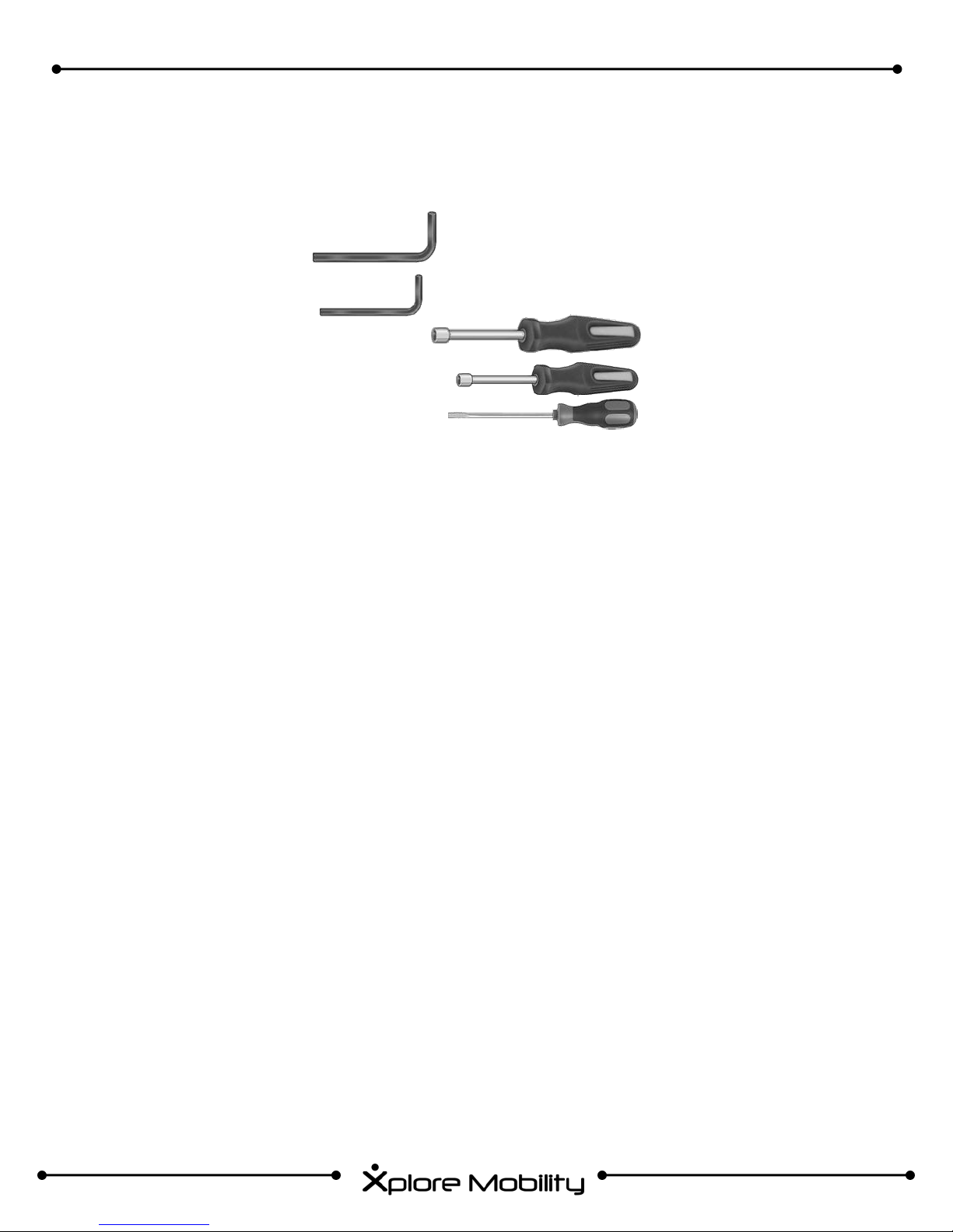
TOOLS NECESSARY FOR MAINTENANCE
Tools Required:
5/32” Hex Wrench
1/8” Hex Wrenches
7/16” Nut Driver or Open End Wrench
3/8” Nut Driver or Open End Wrench
Slotted Screw Driver
“Xplore Your World!”
IX. REPAIR & REPLACEMENT PARTS
A. REPAIR
For all repairs (including tire puncture), contact local authorized dealer
B. REPLACEMENT PARTS
For all replacement parts, contact local authorized dealer.
X. EXPECTED USEFUL LIFE & RECYCLING
A. EXPECTED USEFUL LIFE
Useful life of chair is expected to exceed eight (8) years.
B. RECYCLING
To recycle chair, contact your local authorized dealer for information on recycling.
34

“For kids who like to move!”
- This Page Intentionally Left Blank -
35

pure Functionality
Xplore Mobility
112-1 Rock Road
Belgrade, Montana 59714
PH: 888-575-9225
www.xploremobility.com
© 2011
Xplore Mobility
 Loading...