

Page 1

User Guide
GeneSys Pen Tablet Computer
Page 2

Welcome
Congratulations! We are pleased to add you to the growing list of “Xplorers” who have
chosen our innovative GeneSys® Pen Computing System as their mobile computer platform.
The GeneSys® System has been designed, tested and manufactured with a very specific
objective in mind…to meet the needs of today’s mobile workers. The real world offers
environmental and physical challenges that must be met with a mobile computing system
that not only works the way you do, but also can take the abuses of everyday wear and tear.
The GeneSys System design is based upon years of experience in rugged mobile
applications.
Advanced technology, innovative designs and a rugged body are just a few of the highlights
of your GeneSys System. Equally important is Xplore’s commitment to ensuring you are
treated with the same respect and honesty you offer to your customers and peers every day.
Thank you for choosing Xplore and enjoy your journey through our world of mobile
computing.
The Xplore Team
October 2001 Page 2 P/N 96-000001-017, Version Q301
Page 3

Highlights
As one of the most comprehensive wireless pen computing systems available, your GeneSys System
offers innovative features that allow you to take advantage of the most sophisticated application
software and peripheral configurations available.
§ High visibility Color LCDs, combined with a unique optics technology provides industry-leading
visibility in challenging lighting conditions including direct sunlight.
§ Integrated System that has been designed as a single pen/touch-based mobile computing system
including an innovative Pentium® powered pen computer, comprehensive expansion module(s)
and docking options.
§ Performance Driven Design with Intel® Pentium® III 500 MHz processor integrated into a unique
Main Logic Board design which offers Peripheral Component Interconnect (PCI) BUS technology,
256K of L2 Cache, 8MB of Video memory and other “Performance Accelerators”.
§ Multimedia Ready System with ATI video controller and Sound Blaster compatible audio
components brings applications to life.
§ Rugged Magnesium Housing combined with a patented bumper protection system and
components manufactured for extreme conditions means that the GeneSys is built to last.
§ Advanced Resistive Touch Screen provides exceptional accuracy, a brighter and clearer screen
through enhanced light penetration and heightened reliability.
§ Adaptable Design, which accommodates multiple PC cards for integrated communication options.
Wireless and peripheral expansion that works with today’s technology and can accommodate the
new technology of tomorrow.
§ Rugged Quick Release Docks provide a secured, mechanical docking system that ensures
positive docking and overall reduction in stress on the docking connectors.
§ Dual USB ports are protected in a recessed portion of the patented bumper system and provide
instant connectivity to a growing universe of USB compliant peripherals.
As you “Xplore” your GeneSys Mobile Computing System, you will discover many performance-based
features. A number of accessory and peripheral options are also available to support your entire
system.
Please note: Xplore Technologies® Corp. and its 100% owned subsidiaries, Xplore Technologies®
Corporation of America or Xplore Technologies International may be referenc ed throughout this manual
by various names such as Xplore, XPLORE, Xplore Technologies, etc. Please consider these references
interchangeable.
October 2001 Page 3 P/N 96-000001-017, Version Q301
Page 4

Regulatory Notices
FCC (Notice for users in the United States of America and Canada.)
WARNING – FCC Regulations state that any unauthorized changes or modifications to this
equipment not expressly approved by the manufacturer could void the user’s authority to operate this
equipment.
The GeneSys computer and the Quick Release docking station comply with Part 15,
Class B of the FCC Rules. Operation is subject to the following two conditions: (1) this device may not
cause harmful interference, and (2) this device must accept any interference received, including
interference that may cause undesired operation.
This Class B digital apparatus meets all requirements of the Canadian Interference-Causing
Equipment Regulations.
Trade Name: Xplore Technologies ® Corp.
Model: GeneSys
®
II and GeneSys
®
Maximus
Responsible Party: Xplore Technologies ® Corp.
11675 Jollyville Road, Suite 150, Austin Texas, 78759
Attention: VP of Engineering
This personal computer system consists of the following components:
Component Supplier Address Model Compliance
Computer Assembly SMTC 15700 Long Vista Drive
Computer
Motherboard
Dock Assembly
Delta Electronics, Inc. 186 Ruey Kuang Road, Neihu
Apex Integrated
Manufacturing, Inc.
Austin, Texas 78728
Taipei 114, Taiwan, R.O.C.
8006 Cameron Road
Austin, TX 78754
GeneSys II and
GeneSys Maximus
GeneSys DOC
Xpander and Quick
Release Dock
DOC
DOC
Equipment Classification: FCC Class B Assembly
Type of Product: Pen-Based Computer with Intel ® Pentium ® III 500MHz
Processor and Docking System.
Chipset: Intel ® Pentium III uPGA-2
Manufacturer: SMTC, Delta Electronics
CE (Notice for users in the countries that are part of the European Union)
The European Conformity marking on this product means that this product complies with both the
EMC Directive and the Low Voltage Directive of the European Union. Compliance with these
directives implies conformity with the following European Norms:
§ EN55022=”Limits and Methods of Measurement of Radio Interference Characteristics for
Information Technology Equipment”
§ EN50082-1=”Electromagnetic Compatibility-Generic Immunity Start Part 1: Residential,
Commercial, and Light Industry”
§ EN60950=”Safety of Information Technology Equipment”
October 2001 Page 4 P/N 96-000001-017, Version Q301
Page 5

Safety Information
General Information
• Except as described elsewhere in this manual; refer all servicing to qualified personnel.
Immediately shut off the computer and refer for servicing under the following conditions:
• When the power cord or plug is damaged or frayed.
• If the computer has been dropped and the housing has been damaged.
• Turn off the computer and disconnect the AC cord before cleaning.
Battery Information
Handling
• Never put the battery pack in a fire, as it could explode and cause injury.
• Do not attempt to open or alter the battery pack.
• Do not allow liquids to come in contact with the battery pack.
• Do not solder to the battery terminals.
• Remove battery from system before shipping or storing.
Charging
• Charge the battery pack only with the AC and/or DC adapter(s) or desktop chargers provided by
Xplore.
Discharging
• Do not use the battery pack for any purpose other than powering the GeneSys computer.
Storage
• Store the battery pack in a cool and dry place.
• Recharge the battery pack after storage, before use.
• If the GeneSys is scheduled to be away from a power source (AC or DC) for any length of time,
please remove the battery pack from the GeneSys and properly store it until further use is
required.
Conditioning
• Must be conditioned prior to initial use to ensure optimal battery performance and life.
CAUTION:
If a battery is incorrectly replaced there is danger of explosion. Replace only with the same or
equivalent type recommended by the manufacturer. Discard used batteries according to the
manufacturer’s instructions.
FOR A COMPLETE ELECTRICAL DISCONNECTION, PULL OUT THE AC/DC PLUG AND
REMOVE THE BATTERY.
Copyright
It is the intent of XPLORE that this product be used in full compliance with the copyright laws of the
United States and Canada as well as countries where Xplore is actively selling its products. In
addition, it is also the intent of Xplore that prior permission be obtained from copyright owners
whenever necessary.
Product Information and Customer Assistance
For Product Information and Customer Assistance:
Inside North America Call: 1-888-449-7567 Xplore Technologies Corp.
Outside North America Call: 358-9-8545-800 Xplore Technologies International
October 2001 Page 5 P/N 96-000001-017, Version Q301
Page 6

About this Manual
Disclaimer
This manual has been validated and reviewed for accuracy. The instructions and descriptions it
contains are accurate for the GeneSys Pen Computers at the time of this manual’s production.
However, succeeding computers and manuals are subject to change without notice. Xplore assumes
no liability for damages incurred directly or indirectly from errors, omissions or discrepancies between
the computer and the manual.
Information in this manual is subject to change without notice and does not represent a commitment
on the part of Xplore Technologies Corp. or Xplore Technologies Corporation of America, (“Xplore”).
Xplore shall not be liable for technical or editorial errors or omissions contained herein; nor for
incidental or consequential damages resulting from the furnishing, performance, or use of the
material.
Xplore strongly recommends that separate permanent written records be kept of all important data.
Data may be lost or altered in virtually any electronic memory product under certain circumstances.
Therefore, Xplore assumes no responsibility for data lost or otherwise rendered unusable whether as
a result of improper use, repairs, defects, battery replacement, use after the specified battery life has
expired, or any other causes.
Xplore assumes no responsibility directly or indirectly, for financial losses or claims from third persons
resulting from the use of this product and any of its functions, such as stolen credit card numbers, the
loss or alteration of stored data, etc.
Last Revised: October 2001.
Copyright
© 1997, 1998, 1999, 2000, 2001 Xplore Technologies Corp. All rights reserved. Under the
copyright laws, this manual cannot be reproduced in any form without the prior written permission of Xplore. No patent liability
is assumed, with respect to the use of the information contained herein.
GeneSys User Guide – 2nd Edition, October 2001
Trademarks
Xplore Technologies® and GeneSys® are registered trademarks of Xplore Technologies Corporation of America.
Intel® Pentium® is a registered trademark of Intel® Corporation.
IBM and PS/2 are trademarks of International Business Machines Corporation.
Microsoft, MS-DOS, Windows, and the Windows Logo are trademarks of Microsoft Corporation.
All other brand and product names not mentioned here, but referenced throughout this document are trademarks or registered
trademarks and are the property of their respective holders.
Warranties
Xplore’s Standard Limited Warranty included with every shipment applies to all Xplore products. No other Warranties, whether
implied or actual, will be authorized by Xplore.
October 2001 Page 6 P/N 96-000001-017, Version Q301
Page 7

General Precautions
Xplore computers are designed to optimize safety, minimize strain and withstand the rigors of
portability. However, certain precautions should be observed to further reduce the risk of personal
injury or damage to the computer.
Be certain to read the general precautions below and to note the cautions included in the text of the
manual.
Heat Injury
Avoid prolonged physical contact with the exposed metal surfaces on the front and back of the
computer. If the GeneSys computer is used for long periods, its surface can become warm. While the
temperature may not feel hot to the touch, if you maintain physical contact with the computer for a
long period of time (if you rest the computer on your lap for a defined period of time, for example)
your skin might suffer low -heat injury.
PC Card Overheating
Some PC Cards (or PCMCIA) can become hot with prolonged use. This is the same for any mobile
computer. If two cards are installed, both can become hot even if only one is used extensively.
Overheating of a PC Card can result in errors or instability in the PC Card operation. Also be careful
when you remove a PC Card that has been used for a long period of time.
Pressure or Impact Damage
Do not apply heavy pressure to the computer or subject it to repetitive strong impacts. Excessive
pressure or impact can cause damage to computer components or otherwise cause malfunctions.
Drops
The GeneSys computer is a full-powered, mobile computer and as such is weighted accordingly.
Although the weight is equally distributed to ensure proper balance, the actual weight of the computer
could cause injury if dropped onto someone’s person. Please take care not to drop the computer on
any vulnerable areas.
Cumulative drops of the computer may result in damage and is not recommended. Continual or
excessive drops due to misuse or abuse will not be covered by Xplore’s warranty program.
October 2001 Page 7 P/N 96-000001-017, Version Q301
Page 8

Contents
Chapter 1: GeneSys System Overview 9
Provides a brief overview of the GeneSys Pen Computer and descriptions of key product features.
Chapter 2: Quick Start 13
Provides step-by-step instructions to help you setup and begin using the computer as quickly as
possible. You should read this chapter first before you undertake any operations.
Chapter 3: Basic Operations 16
Explains the basic operations of power sources, pen and touch inputs and peripheral connections.
Chapter 4: Power Management and Battery 23
Describes how to effecti vely manage power and use the battery packs.
Appendices 27
Provides advice on the routine care and maintenance of the computer, technical specifications, and
how to run the setup utility to change system settings.
Appendix A: Setup Utility 27
Appendix B: Care and Maintenance 40
Appendix C: Specifications 42
Appendix D: Glossary 43
October 2001 Page 8 P/N 96-000001-017, Version Q301
Page 9

CHAPTER 1
Rubber
Power Button, Control
Docking Locator Pads
Display
Logo
Power Jack and
USB Host Port
GeneSys Overview
This Chapter provides an overview of your GeneSys Mobile Computer along with a brief description
of key features and functions.
Xplore Your GeneSys
Grips
(Right & Left
Sides)
Keypad & Indicators
GeneSys II
Screen
USB Ports
AC/DC Input Jack
USB Hub Port
Power Button, Control
Keypad and Indicators
Display Screen
USB Host Port
AC/DC Input Jac k
USB Hub Port
Docking Locator Pads
Logo Plate
Rubber Gri ps
Figure 1.1 – Front and Right Side View of GeneSys II
Plate
The power button is located on the membrane keypad. In addition, the keypad has screen
brightness control buttons as well as indicators for Pow er, Docking, Battery and Hard Drive
activity. Also, a hidden PC speaker provides basic system sounds. See Chapter 3 for more
details.
The LCD displays high-contrast text and graphics. See Appendix for specifications.
A USB host is also called a “root” and controls all traffic on the bus. It is typically
implemented as a separate peripheral device with a cable that plugs into a port on the hub.
Can also act as a hub. An example would be a USB floppy drive.
The AC and/or DC adapter plugs connect to this socket. Use only the model of adapter that is
supplied by Xplore. Using the wrong adapter can damage your computer.
Hubs are wiring concentrators and enable the multiple attachment characterist ics of the USB.
Each hub converts a single attachment point into multiple attachment points. Hubs can detect
attach and detach at each downstream. An example would be a USB hub port used to
connect multiple USB devices.
These are rubber pads designed to protect the top and bottom of your computer and to assist
you in properly docking your computer. More detail is provided later in this manual.
This is the plate where the Xplore Technologies brand logo is placed.
The rubber grips are provided to aid in shock protection of your computer and to provide a
tactile, ergonomic surface for holding your computer. Facing the front of the computer, the
upper left and both right hand grips are assembled at the factory and should not be removed.
The lower left grip is removable in order to access the battery compartment. See procedure
for accessing the battery later in this manual.
(Top & Bottom)
October 2001 Page 9 P/N 96-000001-017, Version Q301
Page 10

Rubber
Power Button, Control
Display
Power Jack and
GeneSys Maximus
Docking Locator Pads
Grips
(Right & Left
Sides)
Figure 1.2 – Front View of GeneSys Maximus
Keypad & Indicators
Screen
(Top & Bottom)
USB Ports
Power Button, Control
Keypad and Indicators
Display Screen
USB Host Port
AC/DC Input Jack
USB Hub Port
Docking Locator Pads
Rubber Grips
The power button is located on the membrane keypad. In addition, the keypad has screen
brightness control buttons as well as indicators for Power, Docking, Battery and Hard Drive
activity. Also, a hidden PC speaker provides basic system sounds. See Chapter 3 for more
details.
The LCD displays high-contrast text and graphics. See Appendix for specifications.
A USB host is also called a “root” and controls all traffic on the bus. It is typically
implemented as a separate peripheral device with a cable that plugs into a port on the hub.
Can also act as a hub. An example would be a USB floppy drive.
The AC and/or DC adapter plugs connect to this socket. Use only the model of adapter that is
supplied by Xplore. Using the wrong adapter can damage you r computer.
Hubs are wiring concentrators and enable the multiple attachment characteristics of the USB.
Each hub converts a single attachment point into multiple attachment points. Hubs can detect
attach and detach at each downstream. An example would be a USB hub port used to
connect multiple USB devices.
These are rubber pads designed to protect the top and bottom of your computer and to assist
you in properly docking your computer. More detail is provided later in this manual.
The rubber grips are provided to aid in shock protection of your computer and to provide a
tactile, ergonomic surface for holding your computer. Facing the front of the computer, the
upper left and both right hand grips are assembled at the factory and should not be removed.
The lower left grip is removable in order to access the battery compartment. See procedure
for accessing the battery later in this manual.
October 2001 Page 10 P/N 96-000001-017, Version Q301
Page 11

Docking
Connector Port
Certification
Seale
d Battery
Product
Guide Pin Holes for Dockin
g Carry Handle Holes
IRDA Lens
Antenna Port Hole
Label
Figure 1.3- Back and left side view of GeneSys II
Docking Connector Port
Sealed Battery
Compartment
Product Label
Certification Label
Compartment
Label
This port allows the GeneSys computer to dock to the Xpander and Quick Release docking
stations. More details are provided later in this manual.
Located behind the outer lower, left rubber grip is the battery compartment. Instructions are
provided later in this manual.
This label includes the product brand name and unit serial number as well as bar code.
The appropriate emissions and safety certification labels are strategically located on the
back of the tablet in pre-defined cut-out sections.
IRDA Lens
Carry Handle Holes
Guide Pin Holes for
Docking
Antenna Port Hole
(optional)
Figure 1.4- Top View of GeneSys II
Infrared communication device that allows communications with other IRDA devices i.e.
computers, printers, PDAs.
These holes are used to affix the carry handle to the GeneSys tablet.
These holes are used as locators to ensure positive docking connections to the GeneSys
docking stations.
A cable, upon which an antenna will be mounted, exits this hole. This hole is integrated into
the GeneSys tablet when an internal wireless option is ordered.
October 2001 Page 11 P/N 96-000001-017, Version Q301
Page 12

Key Features
The GeneSys incorporates the following features:
Microprocessor
Level 2 Cache
Memory
Video RAM
Display
Graphics Controller
Digitizer
Battery Pack
Backup Batteries
Built-in Hard Drive
Docking Interface Port
Stylus (pen or touch)
Plug and Play
The GeneSys computer is equipped with an Intel Pentium® III processor. It operates at 500MHz
and incorporates a math co-processor and 256K of internal L2 cache memory. A power
management system called ACPI is used to save battery power.
A 256KB level 2 cache is provided to maximize performance.
The GeneSys computer comes with 64 Megabytes (MB) of Random Access Memory (RAM),
expandable to 256MB.
The GeneSys computer provides 8MB of RAM for video display.
GeneSys II
A 10.4” Ultra Hi-Brite TFT color LCD panel supports high-resolution video graphics and employs a
PCI bus for superior performance.
GeneSys Maximus
A 12.1” Active Transflective color LCD panel viewable in all lighting conditions.
The graphics controller incorporates the PCI bus to maximize performance and enable flicker-free
display. It also enables up to 16.7 million touches on the computer’s LCD panel.
The GeneSys computer has an integrated resistive digitizer that accepts both pen and touch input.
The digitizer is embedded into the glass to maximize performance and accuracy.
A rechargeable Lithium Ion battery pack powers the GeneSys tablet.
An internal battery backs up the internal Real Time Clock (RTC) and calendar.
The GeneSys computer has an integrated 2.5” ruggedized hard drive (HDD) with a capacity up to
20 GB.
This port enables connection to any of the GeneSys docking stations and aides further expansion.
The stylus is an intuitive input device for operating a computer. It provides the functionality of a
mouse with the familiarity of a regular pen or the touch of a finger. The stylus can be used for
basic pointing and tapping or for handwriting right onto the integrated digitizer.
When you connect an external device to the computer or vehicle dock, Plug and Play capability
enables the system to recognize the connection and makes the necessary configurations
automatically. This feature is effective only with Windows® 9x or 2000.
Special Features
The following features are either unique to the GeneSys or are advanced features, which make the
computer more convenient to use.
Hardware Setup
Pen/Touch Utility
Automatic Display
Standby
Automatic HDD
Power Off
Low Battery
Automatic Suspend
Heat Dispersal
Magnesium Housing
This program lets you customize your hardware settings according to the way you work with your
GeneSys computer and the peripherals you use.
This program lets you customize your digitizer settings according to the way you work with your
GeneSys computer. The pen/touch interface can be configured by the user to accommodate their
style.
Power is automatically turned off to the LCD panel when there is no pen, touch or keyboard input
for a time specified in the hardware setup program. Power is restored when the stylus or finger is
touched on the screen or any key on the optional keyboard is pressed. Content is not lost when
display goes into standby mode, however battery performance is improved.
Power is automatically turned off to the hard disk drive when it is not accessed for a time specified
in the hardware setup program. Power is restored when the hard disk is accessed.
When battery power is exhausted to the point that the computer operation cannot be continued,
the system provides a visu al warning that the battery is low and the system will be shut down. An
audio warning in the form of a beep is also emitted. After approximately 60 seconds, the system
will enter low power state “suspend mode”. It is important to note that AC or DC pow er must be
applied to the unit as quickly as possible after the warning has been issued. Once external power
has been connected, a new fresh battery can be swapped in or the user can continue to use
external power.
The Pentium® processor has relatively high power consumption compared to earlier CPU’s.
Therefore, it has greater potential for overheating, especially at higher processing speeds. To
protect from overheating the GeneSys computer uses special materials to move heat away from
the processor to the computer’s case and out into the air. It is normal for the case to become
warm to the touch after prolonged operation, and this is expected as part of a thermal
management system.
The GeneSys housing is designed for harsh environments. The metal structure is much stronger
than plastics and provides enhanced protection for the internal electronics.
October 2001 Page 12 P/N 96-000001-017, Version Q301
Page 13

CHAPTER 2
Attach AC/DC
Attach cord
GeneSys
Quick Start
Your computer is designed and pre-configured for easy setup and use. This chapter describes the
steps you should follow to get your GeneSys System up and running as quickly as possible. You
should read this chapter first. Although many of the instructions and recommendations are common
sense, we want to ensure that you have your GeneSys System configure d as quickly as possible.
We recommend that you read the entire manual for a comprehensive overview of the entire GeneSys
system and its operation.
Connecting to AC Power
The rechargeable battery pack, AC adapter or DC adapter can power the computer. See the next
chapter for more information on power sources. The first time you use the computer, be sure to
perform the steps below:
1. Make sure the computer is turned off.
2. Connect the AC adapter cord to the computer.
3. Connect the AC power cord to the AC adapter.
[WARNING] – Always use the AC adapter supplied with the computer. Using other
AC adapters may damage the computer. Always hold the AC adapter cord by its
plug.
4. Plug the AC power cord into a wall outlet.
GeneSys Tablet
Input
Figure 2.1 Connecting to AC Pow er Figure 2.2 Turning Power ON
Note: Alternatively power may be provided by an optional external DC automobile adaptor or
connected directly via the GeneSys Xpander and Quick Release Docks for in-vehicle, forklift or
mobile communication cart installation.
AC Brick/ adapter
set
Power Controls
October 2001 Page 13 P/N 96-000001-017, Version Q301
Page 14

Turning Power On
Screen
Figure 2.3 Screen Brightness Adjustment
for GeneSys II
Figure 2.4 Screen Brightness Adjustment for GeneSys Maximus
Screen
Although we are sure these instructions are unnecessary, we have included these simple instructions
for reasons of completeness. To turn on the power follow these steps:
1. Connect the computer to AC power
2. Press the power button, which is located on the membrane switch (see Chapter 3)
3. Depress the power button for approximately 2 seconds to initiate system response
Note: Do not turn power off immediately after turning on the system. Instead, wait until the operating
system completes booting.
When the power is turned on, the power indicator (on the gray panel above the LCD) lights and the
computer starts.
Adjusting the Screen Brightness
Brightness adjustment buttons have been provided to allow for adjustment for maximum rea dability.
Brightness
Brightness
Removing the Grips
All grips will require minimal effort to remove. However, in the event that the us er experiences
difficulty removing any grip, use the follow these steps:
1. Remove the grip above the grip that covers the battery cover (top left grip).
2. Place the edge of the grip on the edge of a table or firm surface (See Figure 3).
3. Slowly but firmly push the tablet down while a table or firm surface supports the edge of the
grip. (See Figure 4).
4. Remove the grip by hand.
October 2001 Page 14 P/N 96-000001-017, Version Q301
Page 15

Shutting Down the System
To power off the computer, from the Windows 98 or 20 00 Start menu, select Shut Down and then
click Okay. The computer shuts down automatically.
Note: If a file is not saved yet, then a dialog box will appear asking you if you want to save the file
or not.
[WARNING]
• Turning off the power without using the Windows Shut Down feature or resetting the
computer may damage or even wipe out the data.
• Before turning the computer back on, wait at least 3 seconds after turning off the computer.
Turning the power off and on in rapid succession can damage the computer’s electrical
circuitry and/or operating system.
Resetting the System
Software Reset
You can reset the software if you encounter software problems, which lock up the computer. To
reset the system or “reboot”, press Ctrl+Alt+Del keys simultaneously (if the optional keyboard is
attached). Then follow the instructions on the screen: press the Ctrl+Alt+Del keys again. The
computer restarts. This is known as a “warm boot”. If you do not have the optional keyboard
attached then use the power button as outlined below.
[WARNING] Resetting may cause data loss. Use the software reset only if the normal Windows
Shut Down does not work because of software malfunction. Although resetting will not damage
the system, you may lose the data you are processing.
Power Button
You can turn off the computer with the power switch if you encounter hardware or software
problems, which lock up the system. Hold the power button for a few seconds and the computer
will shut down.
[WARNING] Before turning the computer back on, wait at least 3 seconds after turning off the
computer. Turning the power off and on in rapid succession can damage the computer’s electrical
circuitry. By tapping the power button in Windows 98 or 2000 will initiate Windows shutdown.
October 2001 Page 15 P/N 96-000001-017, Version Q301
Page 16
CHAPTER 3
P
ower
F2
Warm
Screen
Figure 3.1 GeneSys
II
Membrane Overview
Screen
Power
F2
Warm
Screen
Screen
Figure 3.2 GeneSys Maximus Membrane Overview
Basic Operations
This chapter describes the basic operations you can perform with your GeneSys Pen Computer.
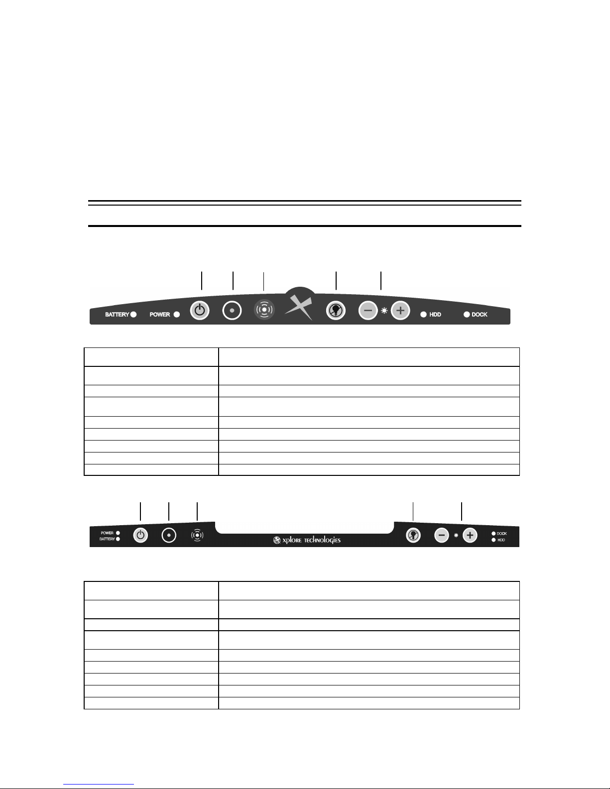
Tablet Membrane
The GeneSys membrane contains several control options as well as indicators to aid in system
use.
Docking
Blackout
Brightness
Power Indicator
Battery Indicator
Power Button
F2 Function Button
Emergency Panic Button
Blackout Screen Button
Screen Brightness Buttons
Hard Drive Indicator
Docking Indicator
Docking
Power Indicator
Battery Indicator
Power Button
F2 Function Button
Warm Docking Button
Blackout Screen Button
Screen Brightness Buttons
Hard Drive Indicator
Docking Indicator
Lets the user know the status of the system; a red light shows when the system is
on or when the system is connected to an external power so urce.
Signals when the battery is in use, being used or is fully charged; a green light
shows when running battery power only and amber when the battery is charging.
Used to turn the system on or off if the system is locked up.
Allow for quick access to the bios during bootup; can also be programmed for
Windows applications.
Sends emergency message; can also be programmed for Windows applications
Turns off power to the backlight while the unit remains on.
Controls the level of brightness for the screen.
Lets the user know when the hard disk drive is in use.
Signals when the system is docked in one of the GeneSys docking solutions.
Blackout
Lets the user know the status of the system; a red light shows when the system is
on or when the system is connected to an external power source.
Signals whe n the battery is in use, being used or is fully charged; a green light
shows when running battery power only and amber when the battery is charging.
Used to turn the system on or off if the system is locked up.
Allow for quick access to the bios during bootup; can also be programmed for
Windows applications.
Sends emergency message; can also be programmed for Windows applications
Turns off power to the backlight while the unit remains on.
Controls the level of brightness for the screen.
Lets the user know when the hard disk drive is in use.
Signals when the system is docked in one of the GeneSys docking solution s.
Brightness
October 2001 Page 16 P/N 96-000001-017, Version Q301
Page 17

Programming Function Button
To program the F2 Function Button use the following steps:
1. Create a shortcut for function on the Windows Desktop.
2. Right click on the shortcut icon and select the Properties option.
3. In the Shortcut Key box delete the word None (default option) then while the cursor is still
in the box press the F2 button on the membrane.
4. After this is done F2 should be displayed in the Shortcut Key box. Select the OK or
Apply button to activate this change
Note: If the user wants to chang e the function key to another function then the current function
must be deleted from the Shortcut Key box. Leave the box blank and press OK or Apply. The
user must re -enter the shortcut for the new function and repeat steps 1-4 for the new function.
Choosing a Power Source
The computer is designed to operate with one of the following power sources:
• AC power from a wall outlet – (external power source 100 to 240 volts).
• DC power from a cigarette lighter in a vehicle – (external power source 11 to 28 volts).
• Lithium Ion battery pack provided with your computer or available as an option.
It is recommended that you use external power whenever possible, relying on the battery pack
only when external power is unavailable or in a mobile only application need.
Using the AC Adapter
The AC adapter provides power for operation and to charge the battery when the AC adapter is
connected to a wall outlet. The AC input voltage can range anywhere from 100 to 240 volts,
making it suitable for use virtually anywhere in the world with the appropriate plug adapter.
The AC power cord provided with the power brick is appropriate for the voltage of your
local area. If you attempt to connect the computer to a wall outlet other than your local
area, check the voltage of the outl et and use an AC power cord appropriate for the outlet.
Using the DC Adapter
The DC adapter provides power for operation and to charge the battery when the DC adapter is
connected to a vehicle cigarette lighter. The DC input voltage can range from 11 to 28 volts,
making it suitable for use in virtually any vehicle. Use only the DC cable supplied by Xplore.
Using the Battery Pack
The rechargeable battery pack allows you to operate the computer without an external power
source. When fully charged, a Li-Ion battery pack can supply power to your computer for up to 4.0
hours (based on APM and normal backlight settings).
The amount of time a battery charge will last depends on the computer’s usage. Applications,
which heavily use the peripherals, like the floppy disk drive, will experience shorter power time.
October 2001 Page 17 P/N 96-000001-017, Version Q301
Page 18
Charging the Battery
To recharge the battery, connect the AC adapter to the computer as described in the previous
section. The external power source used and whether or not the computer is on influences the
charging of a low battery. Using the Xplore provided AC charger will render charging periods of
about 5 hours when the computer is turned off. When the computer is turned on, fully charging a
low battery will take approximately 13 hours.
Alternatively, you can insert the battery pack into the optional desktop charger. Place the battery
pack into the charger with the contact points in place (the battery will stand vertically). The
battery-charging indicator will light red indicating that the battery is charging. Using the Rapid
Rate desktop charger, approximately 1.5 hours are required to fully charge a low battery. When
the battery is fully charged, the indicator light will turn green.
It is recommended that when you initially receive your GeneSys Pen Computer, you run AC
power to the unit, with the battery installed for a minimum period of 8-10 hours. This will provide
a solid initial charge for your battery.
If you have not used the computer for a long period of time, the battery may become
completely discharged. In such a case, recharging may take more time than usual.
Important Note: If you are planning to leave your GeneSys Computer idle, away from either an
AC or DC power source, for any length of time, please remove the battery pack from the
computer.
Checking the Battery Level
Check the battery level as follows:
Shut down the unit as per standard shut down procedures and remove the battery from the
battery enclosure. Press the round tab on the battery pack to light the charge bar (only if battery
shipped with GeneSys has this external battery reader -not all are equipped). The green indicator
will identify the approximate charged state of the battery, i.e. 100%, 75%, etc… It is highly
recommended that when your battery meter reads 25% (or one bar), AC or DC power be applied
to the unit in order to recharge the battery. Alternatively, the battery can be removed and
charged in an external desktop charger. The computer may then be turned back on after
connecting to AC or DC power.
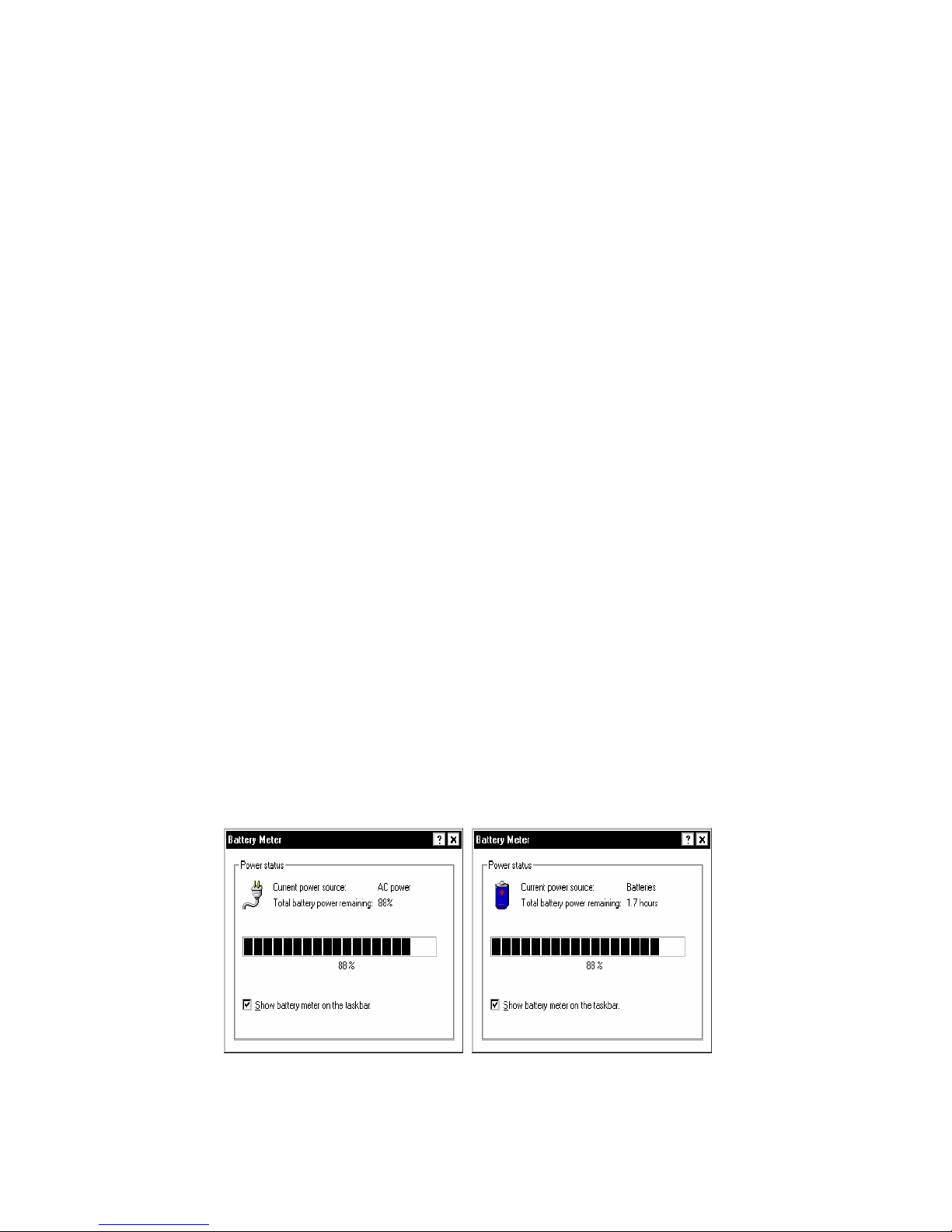
Battery power may also be checked using the battery meter in the System Tray. Double tap on
the battery icon on the System Tray, near the clock. A window will appear indicating the
approximate life of the charge and the percentage of charge left in the battery.
Figure 3.3 Two, Battery Power Status Window
October 2001 Page 18 P/N 96-000001-017, Version Q301
Page 19

The remaining battery amount and remaining time are estimates based upon calculated values. Depending on the actual
usage, the remaining time may be shorter than that indicated.
Using Pen/Touch
In addition to the passive pen, your computer allows you to use your finger as a pointing device.
Most software applications require the use of the “left” mouse button. By tapping on the screen,
your finger, much like the pen, acts as if the left mouse button is being pressed. Your finger or
any other pointing device, will act very much the same. Refer to the Pen instructions below.
Important Note : Please do not use sharp objects or ink-based pens to input to your computer
screen. Damage caused to the screen by inputting via non-approved methods may void the
screen warranty.
Using the Pen
Your computer features a passive pen (stylus) pointing device. The pen combines high-resolution
control and an ergonomic design equally suitable for left -handed and right-handed users. Most
software applications require the use of the “left” mouse button. By tapping on the screen the pen
acts as if the left mouse button is being pressed.
The Pen/Stylus
Figure 3.4 Pen/Stylus
Holding the Pen
Place the pen in your right or left hand in a comfortable writing position.
Move the Pen
The pen acts like an un-tethered mouse. As you move the pen across the display, the pointer on
the screen moves in the same direction across the screen as the pen in your hand. The screen is
very sensitive and will track your movements (you can set this option to your preference, see Pen
Configuration below).
Point and Tap
When you have placed the pen (cursor on the screen) over an icon, menu item or command that
you wish to execute, you can tap on the screen twice rapidly to execute the command. This
procedure is called “point and tap”.
Drag and Drop
You can execute commands or move files by using “drag and drop”. In drag and drop, you
activate a file by pointing and holding the pen down to it. Do not lift the pen. You can then drag
October 2001 Page 19 P/N 96-000001-017, Version Q301
Page 20
the active file around the screen by moving the pen. When you have placed the file where you
want it, for example in a new directory, lift the pen. The file will drop into the new location.
Right clicking
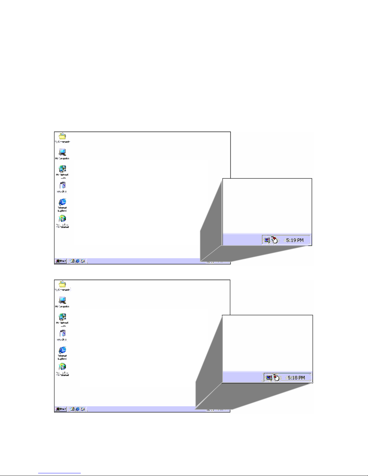
Using the context sensitive menus available with a “right click” facilitates some applications. Since
the stylus used with the GeneSys is passive, a pen switcher utility has been included to allow
right clicking. Open the PenSwitcher utility from the system tray (See Figure 3.2). The ‘mouse’ will
appear. By tapping on this window the stylus will register the “other” click. When the pen touches
the screen the right click menu will appear. After this the click function will automatically revert
back to the left mouse click sett ing. The stylus will remain in this mode until the switcher is
clicked again. Note: The color “Red” on the mouse denotes the active button mode.
Figure 3.5 Right-click Mouse Icon in System Tray
Figure 3.6 Normal Left-click Mouse Icon in System Tray
October 2001 Page 20 P/N 96-000001-017, Version Q301
Page 21
Pen Configuration
Calibrating the pen will ensure better accuracy for your personal use. Since each person holds
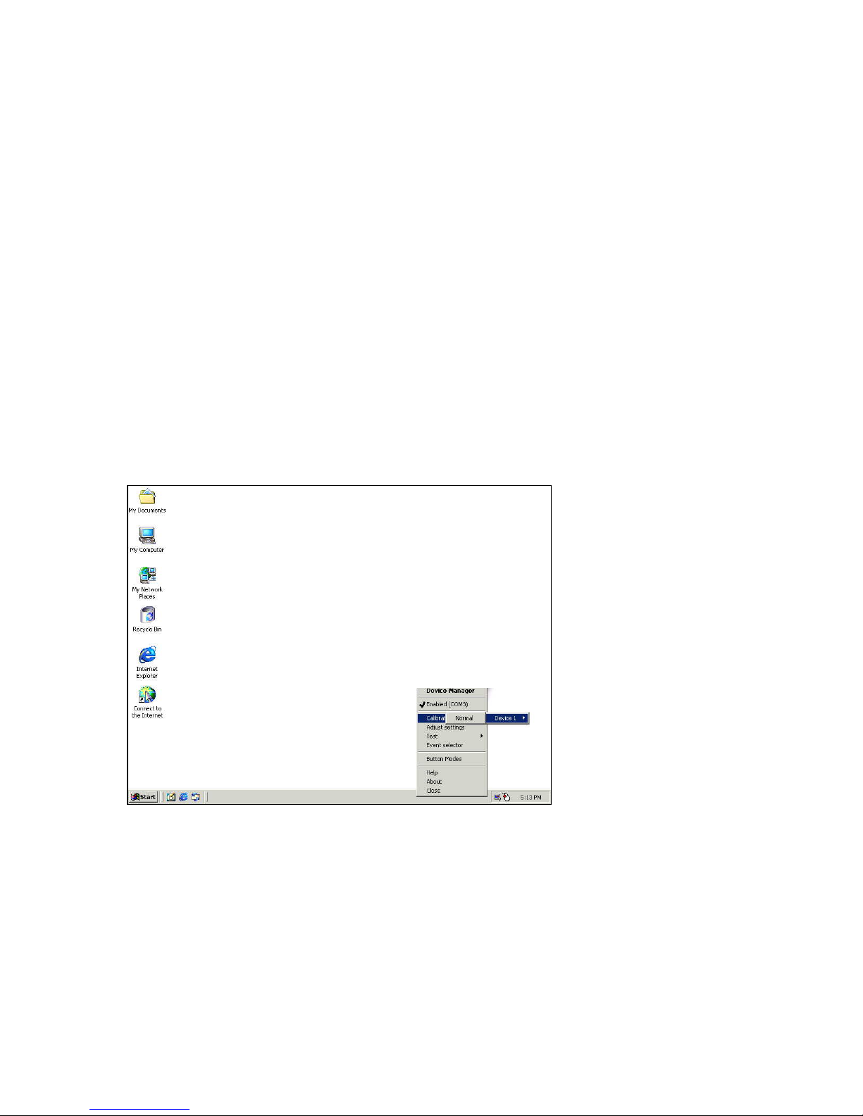
the pen slightly different, it is best to set up the pen for your use. To calibrate the pen for your
particular requirements use one of two paths:
Via the System Tray:
In System Tray double tap the pen on the PenControl Icon on your Windows desktop. A menu will
appear. Choose the Calibrate option then choose Device and then Normal. After this selection
has been made the calibrate screen will appear (See Figure 3.5). Follow the instructions on the
screen and touch the “X” ‘s on the screen as they appear. Tap each “X” only once. Tap the
OK/Close button to return to Windows.
Via the Start Menu:
Select Start then Programs then Touch Screen Utilities. Select the Calibrate option or
Settings then the Calibrate button. This will open a window with a number of tabs. Tap the pen
on the Calibrate button. Follow the instructions on the screen and touch the “X” ‘s on the screen
as they appear. Tap the each only “X” once. Tap the OK/Close button to return to Windows.
Note: It is important to hold the pen as you would during normal operation. This will ensure a
more realistic training exercise with the pen calibration being trained to your particular style. Do
not rest your hand on the screen as you use the pen. This will cause the computer to misread
your actions.
Figure 3.7 Pen Calibration from the System Tray
October 2001 Page 21 P/N 96-000001-017, Version Q301
Page 22
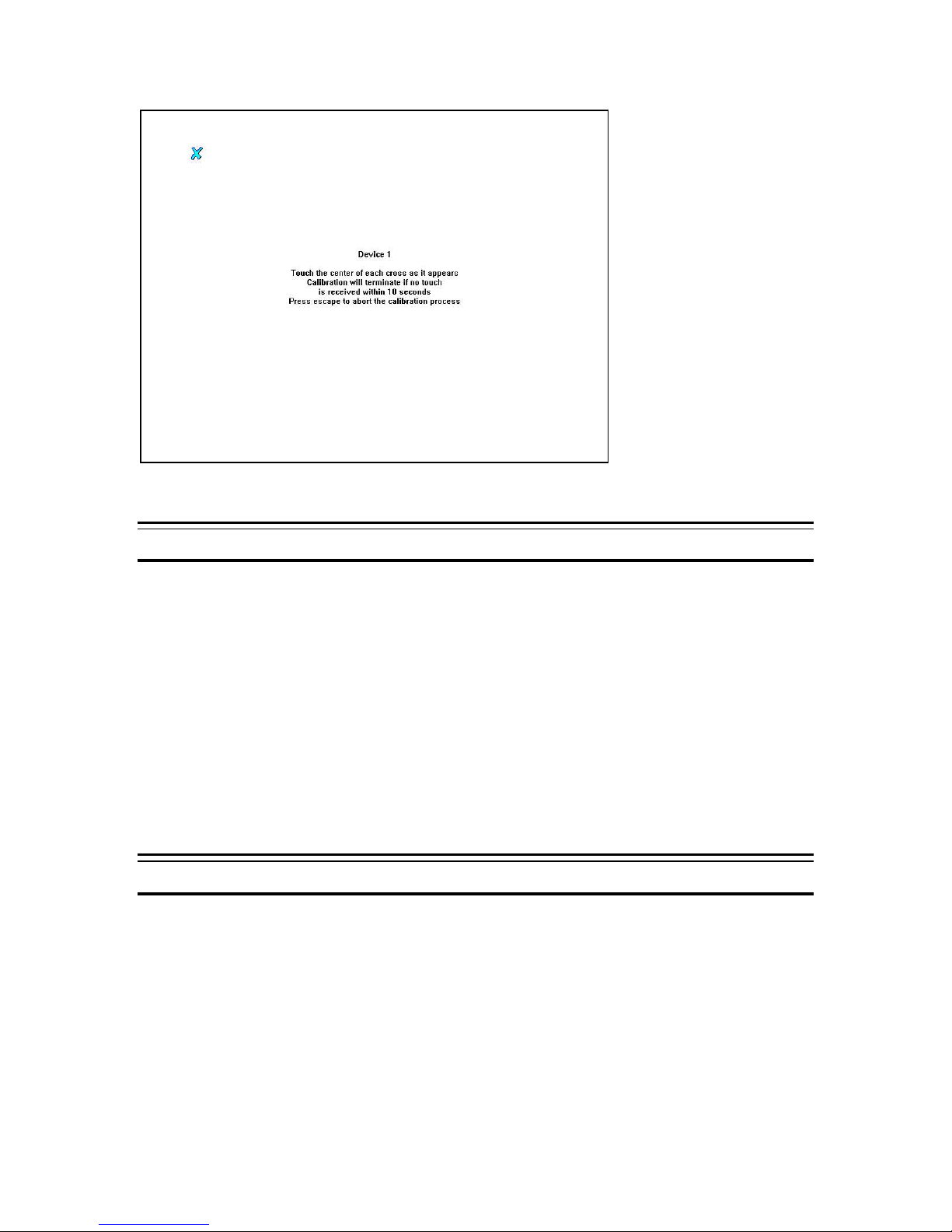
Figure 3. 8 Pen Calibration Screen
Warm Docking
To utilize the warm docking capabilities of the GeneSys utilize the following steps:
1. If the computer is docked and is powered on then press the red warm docking button.
2. Once the system message has appeared on the screen, the tablet can be safely removed
from the dock.
3. Once the tablet has been removed, press the “Okay” button in the message box.
4. This system can now be used remotely as needed.
5. To re -dock the tablet onto the dock, simply re-mount the tablet onto the dock.
6. Once the green dock indicator light appears, the tablet is ready to be utilized again.
Note: It may take a few seconds for the green dock indicator light to appear and for all peripherals
connected to the dock to be recognized by the tablet after re-docking. This function is only
available on the Xpander Plus and GeneSys Quick Dock Plus.
If the system is already powered on, but it has not been undocked and the user wants to dock the
tablet, then follow steps 5 and 6.
Approved Accessory Drivers
The drivers for Xplore’s accessories can be accessed in the X_Disks folder, which resides in the
Options folder under the Windows folders. These drivers can be accessed when a new
accessory is added to the system during the hardware setup browsing process.
October 2001 Page 22 P/N 96-000001-017, Version Q301
Page 23

CHAPTER 4
Power Management and Battery
This chapter explains how to better manage the computer’s power resources and the use of
additional battery packs.
Activating Power Management
Your GeneSys computer incorporates power management feat ures, which allows you to extend
battery life. You should think of your computer’s power conservation features as being organized
into several, sometimes overlapping, levels of management, which together provide both manual
and automatic control over which components of the computer are drawing current at any given
time.
Changing Power Configuration Settings
Power management configurations are set at the factory prior to shipping. However, you can
configure or change the power management settings using the Power menu of the Setup Utility.
Power settings allow you to control current drain by peripheral devices and put them in suspend
mode when not in use. By continually monitoring the state of these devices, and shutting off the
flow of current to idle devices , battery life can be preserved, thereby extending the amount of time
that you can use your computer from battery power.
You can access the Power menu of the Setup Utility to set power management parameters
in the following way:
Press the F2 button when prompted on the screen just after you have turned on or reset the
computer and before Windows starts. To perform this function at least one of the following must
be used
§ USB mouse,
§ USB keyboard or
§ PS/2 keyboard or mouse when docked
Press the “ALT” key to highlight the menu choice. Then press the left or right arrow key to select
the Power menu at the top of the Setup Utility screen.
It is important to note that the following power configuration elements are set at the factory for
maximum battery performanc e. It is highly recommended that these settings not be modified
unless absolutely necessary.
October 2001 Page 23 P/N 96-000001-017, Version Q301
Page 24
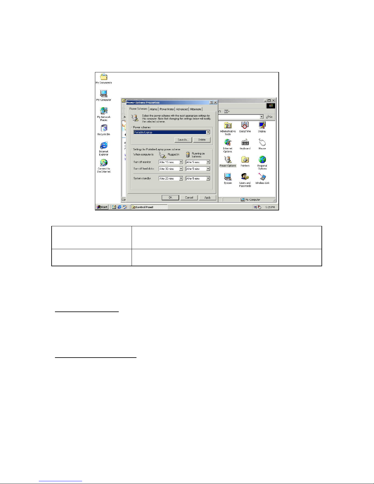
For Power Management under Windows 98 and 2000:
Go to Start then Settings then Control Panel. In Control Panel double -click on the Power
Management icon.
Figure 4.1 –Power Management Properties
Power Savings
LCD Backlight
Allows the user to enable or disable and select power management settings. When
this option is Off, all power management settings specified are ignored. When set to
Maximum Power Savings (the default), Maximum Performance, or Custom power
management is enabled.
When power management is activated, the LCD display will “go to sleep” after a
minute of inactivity. The screen can then be activated by either the touch of the pen
or finger or via the keyboard. This setting is controlled as a screen saver.
Suspend Mode
Suspend mode is the lowest power consumption level your GeneSys computer can
sustain.
Entering Suspend Mode
Suspend mode can be activated in any of the following ways:
• By tapping Suspend on the Windows Start menu, or
• By allowing the unit to enter “sleep” mode due to inactivity
Resuming from Suspend Mode
Normally, resuming from a suspend mode is triggered as follows:
• By tapping any of the keys on the keyboard (if attached), or
• By tapping the stylus to the screen.
• By pushing the Power button.
When a resume event occurs, the system returns to where it was when suspend mode was
entered, e.g. software applications open, the display reappears, etc. It may take several
seconds to return from suspend mode.
October 2001 Page 24 P/N 96-000001-017, Version Q301
Page 25
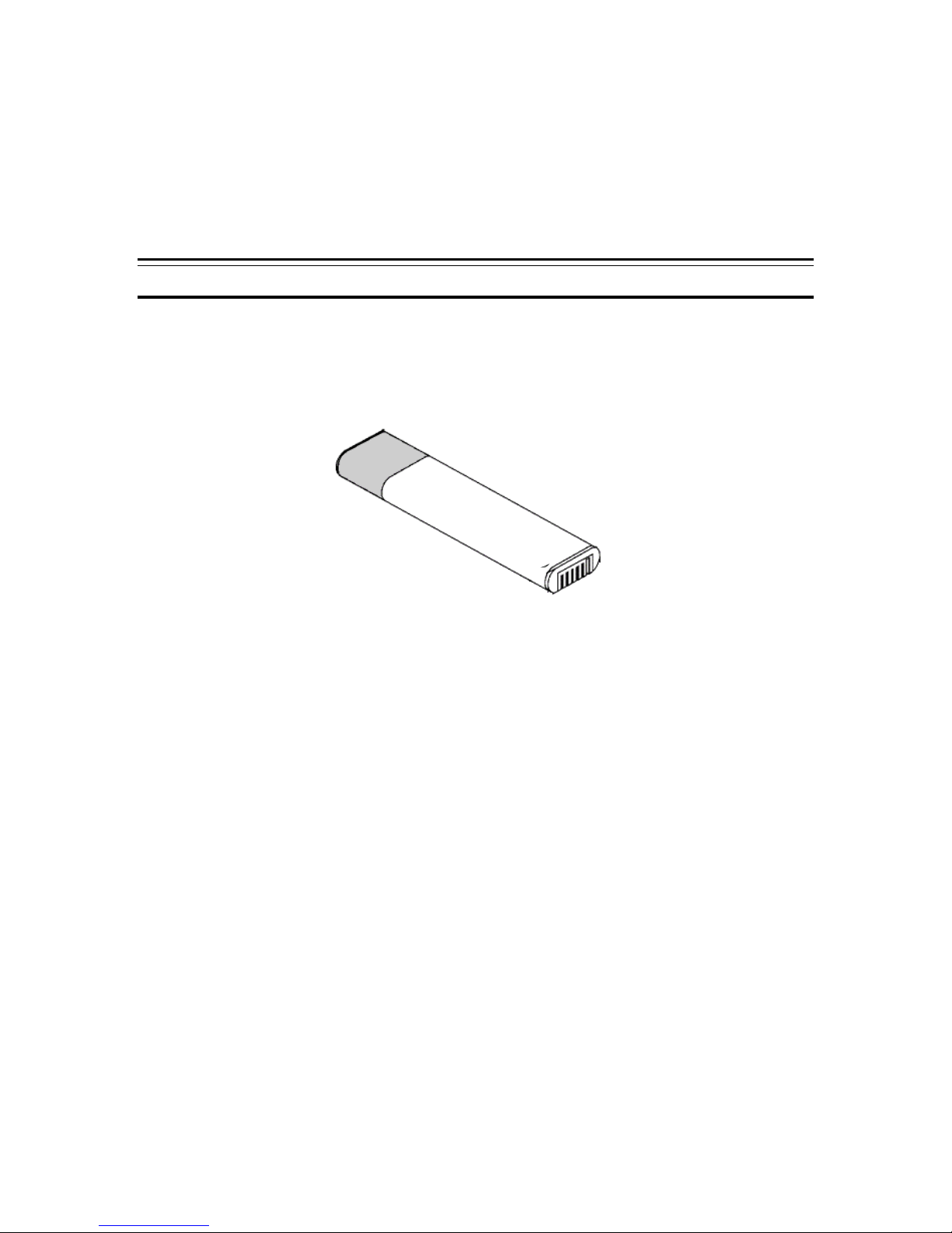
WARNING: When entering or returning from suspended mode, be sure to observe the following
Figure 4.2
-
Lithium Ion Battery
precautions. Otherwise, the computer may not operate correctly after it has resumed from the
suspend mode.
• Do not operate the keyboard (if attached) in the process of entering or returning from
suspended mode
• Before activating suspended mode, terminate any optical or modem communications
Using Battery Packs
The rechargeable battery pack allows you to operate the GeneSys Computer without an external
power source. When fully charged, a battery pack can supply power to your computer for up to 4
hours (based on power management and normal backlight settings).
Your GeneSys Computer supports Lithium Ion battery packs.
To recharge the battery, connect the AC or DC adapter to the computer as described earlier in
this manual. Approximately 3 hours are required to fully charge a low battery.
Alternatively you can recharge the battery by docking the computer into the vehicle dock or by
inserting the battery pack into the optional desktop charging station. See below for more details
regarding this item.
NOTE: Use only battery packs provided by and/or authorized by Xplore. There is a danger of
explosion if the wrong battery type is used. For environmental reasons, do not throw away a
spent battery pack. Please follow you local guidelines for disposing of battery packs.
If you need to operate your GeneSys on battery power for an extended period of time, you may
need to change or “swap” the battery pack to continue battery -powered operation.
Replacing a Battery Pack
Use the following steps to replace a battery pack:
1. Turn off the computer and disconnect the external power. For safest method, disconnect
any peripherals as well. (“Warm Swapping” is not recommended.) Place the computer on
the right side so that the right end is sitting on a flat surface.
2. Remove bottom left grip and open battery door cover.
3. Pull the ribbon on the battery pack to slide it out of the battery chamber.
4. Insert another battery pack into the battery chamber, making sure the battery label faces
the front of the computer (i.e. towards the LCD screen). Ensure that you slide the battery
October 2001 Page 25 P/N 96-000001-017, Version Q301
Page 26

all the way into the chamber so you can actually feel it connect to the internal battery
connector at the other end of the battery chamber.
5. Return the battery door cover and the rubber grip to their original positions. Be sure to
line up grip edges with the slots on the GeneSys tablet to insure ease of replacement and
proper fit and to avoid damage to the grip apparatus.
While you can install an optional battery pack into the computer and charge it like the standard
battery, you can also use the optional battery charger to charge it. See the section below for more
information.
Using the Battery Charger
You can use the optional desktop battery charger to charge battery packs.
Installing a Battery Pack into the Desktop Charger
1. Locate the five (5) pins within the chamber on the battery charger and the five (5) notches on
the bottom of the battery pack.
2. Set the battery onto the 5 pins so that the battery is standing up (vertical) and secure in its
position.
3. Connect the supplied AC adapter to the charger and the wall outlet.
4. You will see the power and charging status lights come on.
NOTE: Some battery chargers have two bays, meaning that you can charge two batteries in the
same charger. These chargers will charge one battery first (first installed) to a complete charge,
then charge the second battery (second installed) to a complete charge.
Reading the Indicators
Power Indicator Meaning
ON (red) The external power source is connected
OFF The external power source is not connected
Battery Charger Indicator Meaning
ON (green) The battery is fully charged
ON (red) Waiting to charge
ON (amber) The battery is charging
Fully charging a battery takes approximately 1.5 hours with the fast charger. The sound
that the charger makes while in operation is the internal fan used to cool the electrical
circuits.
October 2001 Page 26 P/N 96-000001-017, Version Q301
Page 27
Appendix A
Running the Setup Utility
Your GeneSys® computer has been properly set up and configured prior to delivery. However,
you may find it necessary to use the Setup Utility to change system configuration information,
such as date and time, port assignments, or power management settings. The Setup Utility can
be accessed when “Press <F2 > to enter setup” appears at boot time.
The settings you specify with the Setup Utility are recorded in a special area of memory called
CMOS RAM. An independent battery backs up this memory so that it will not be erased when you
turn off or reset the system. Whenever you turn on the power, the system reads the settings in
CMOS RAM and compares them to the equipment check conducted during the power-on-selftest. If an error occurs, an error message is displayed on screen.
Contents of the Setup Utility
The Setup Utility consists of one main page with six (6) menus, which are as follows:
• Startup: time/date, boot controls and passwords (Boot and SCU)
• Memory: cache
• Disks: internal FDC, diskette drives and internal HDC, IDE settings
• Components: COM ports, LPT ports and keyboard
• Power: battery low beep, power saving, suspend controls and resume timer
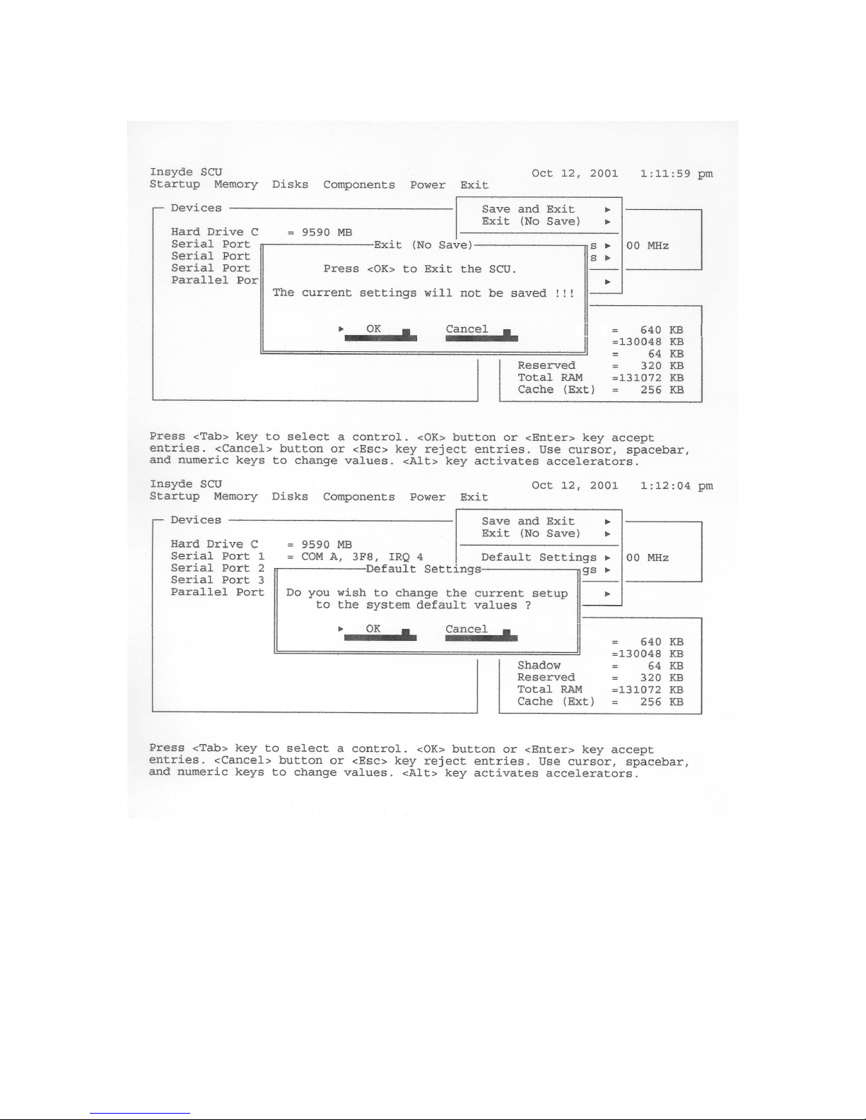
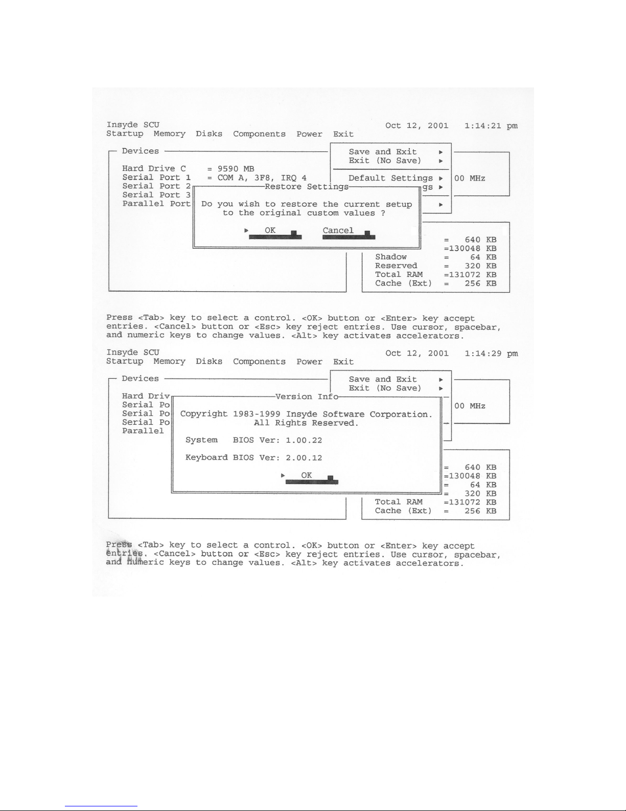
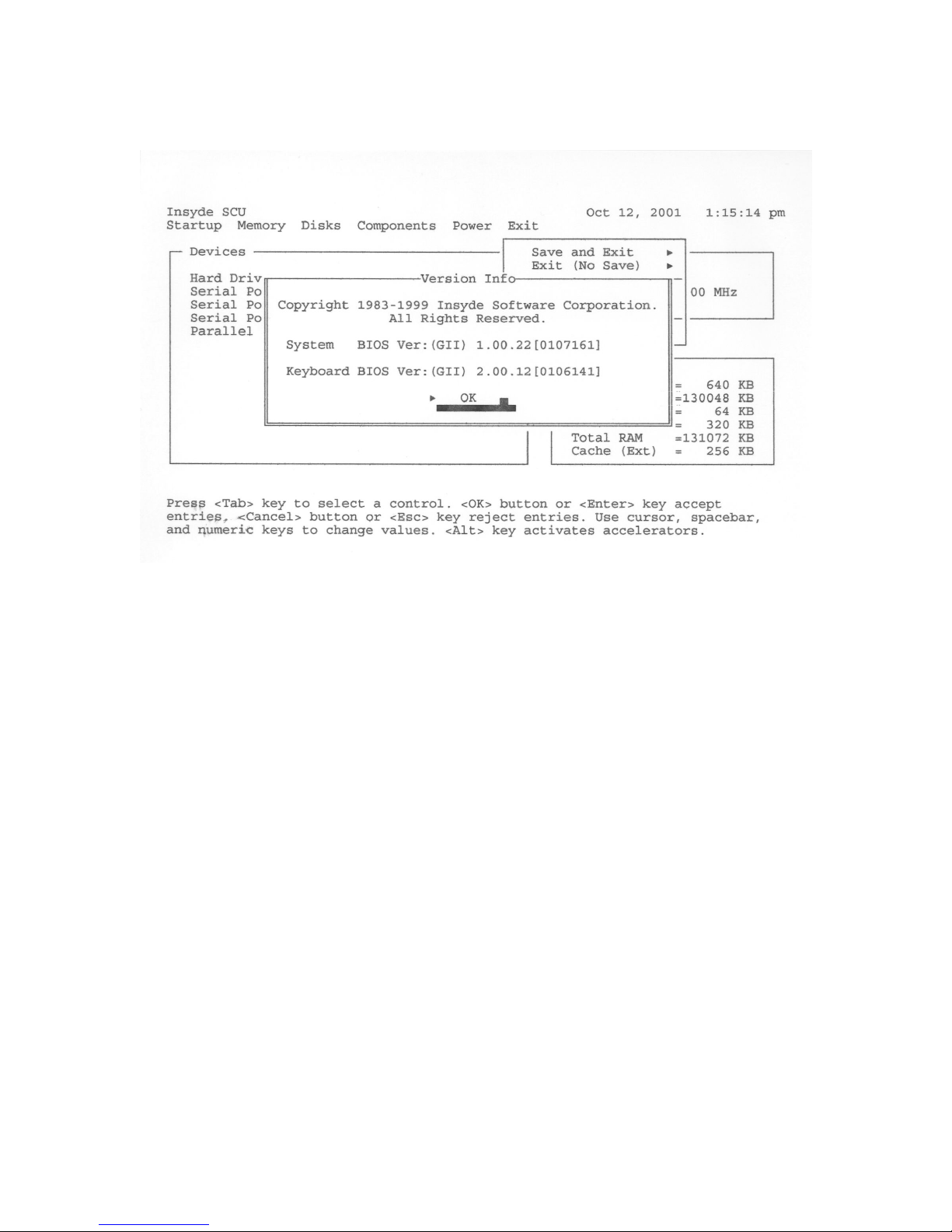
• Exit: exit the Setup Utility, restore settings and bios version information
October 2001 Page 27 P/N 96-000001-017, Version Q301
Page 28
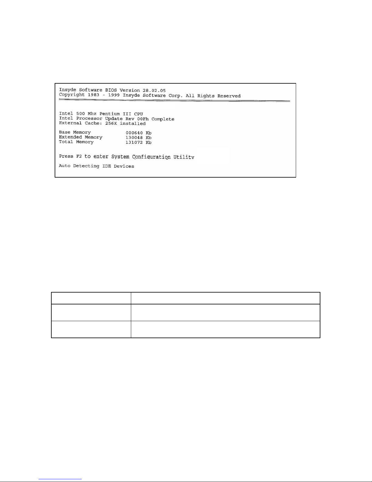
How to Run the Setup Utility
NOTE: You must have a keyboard attached to the GeneSys in order to enter the Setup Utility.
1. Turn on the computer.
2. When Press <F2> to enter SETUP appears, press F2 to display the Setup Utility screen.
3. Change the desired settings.
4. Press ESC to get back to the main Setup Utility screen then use arrow keys to select the Exit
menu.
5. Select one of the following exit methods, then press Enter
• Save and Exit
• Exit (No Save)
• Default Settings
• Restore Settings
• Version Info
6. When Save and Exit or Exit (No Save) is chosen then the system will reboot
Using the Setup Utility
The following keys are used to maneuver among the Setup options and to change values:
Cursor Keys (arrow keys)
Spacebar key
ESC key
Use the cursor keys to move from one option to another.
Press the Space key to increase the numeric value or change the next value of an
option.
Press this key to enter the Exit menu. From the Exit menu, you can make default
settings or load previous value s and so on.
Or you can use the build-in PS/2 mouse to move around and select options.
October 2001 Page 28 P/N 96-000001-017, Version Q301
Page 29
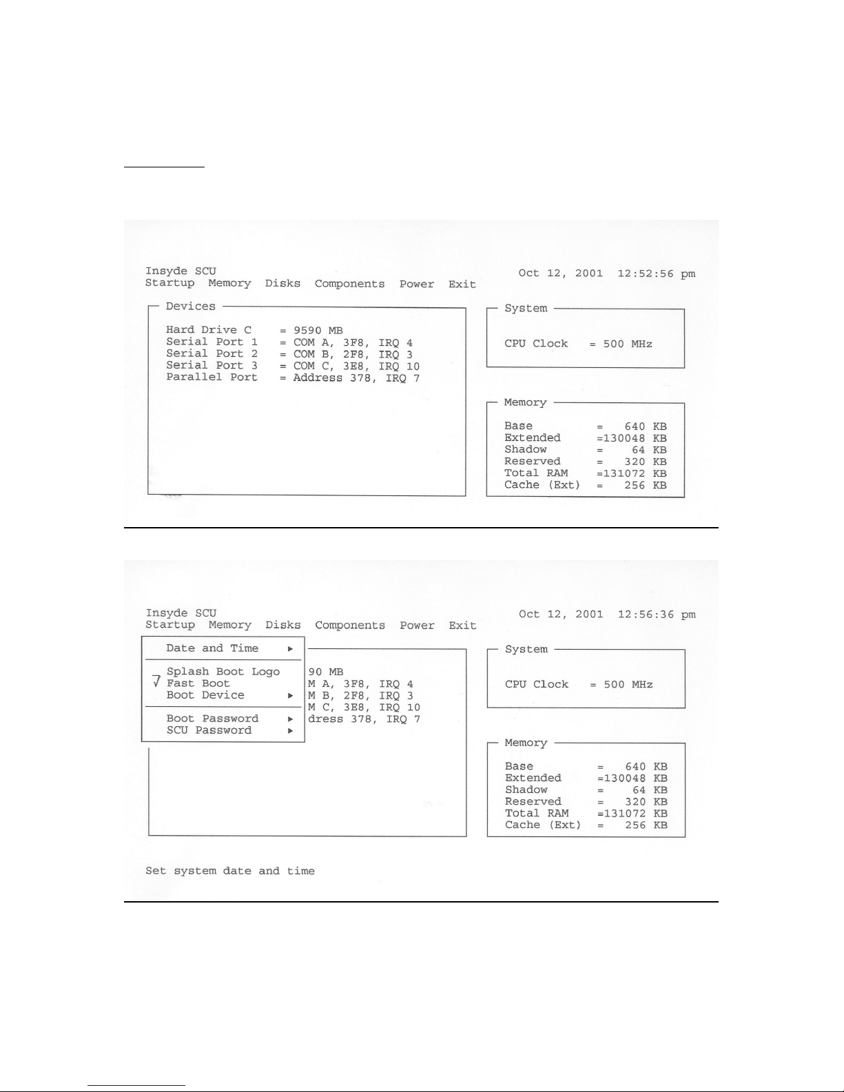
Settings That You Can Change
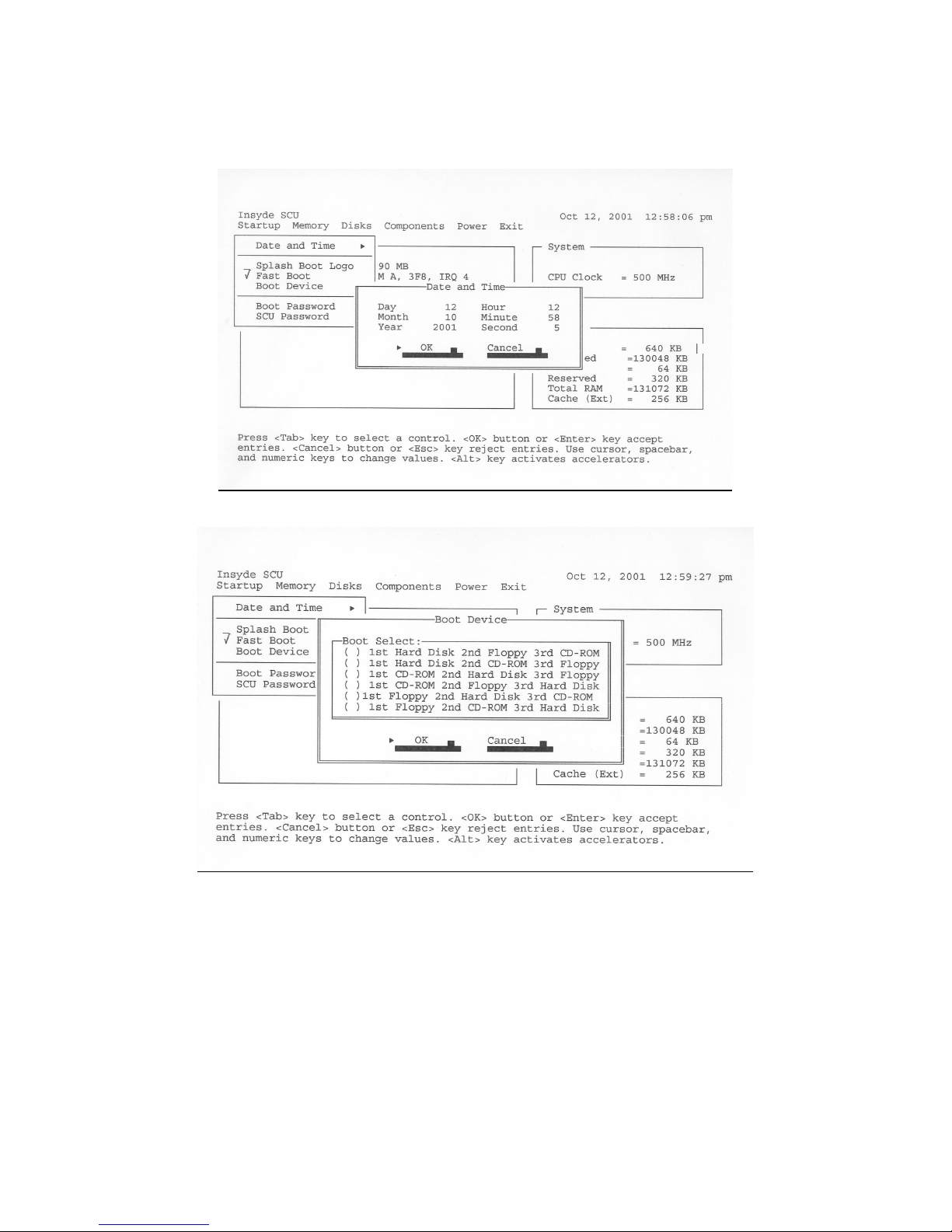
Startup Menu
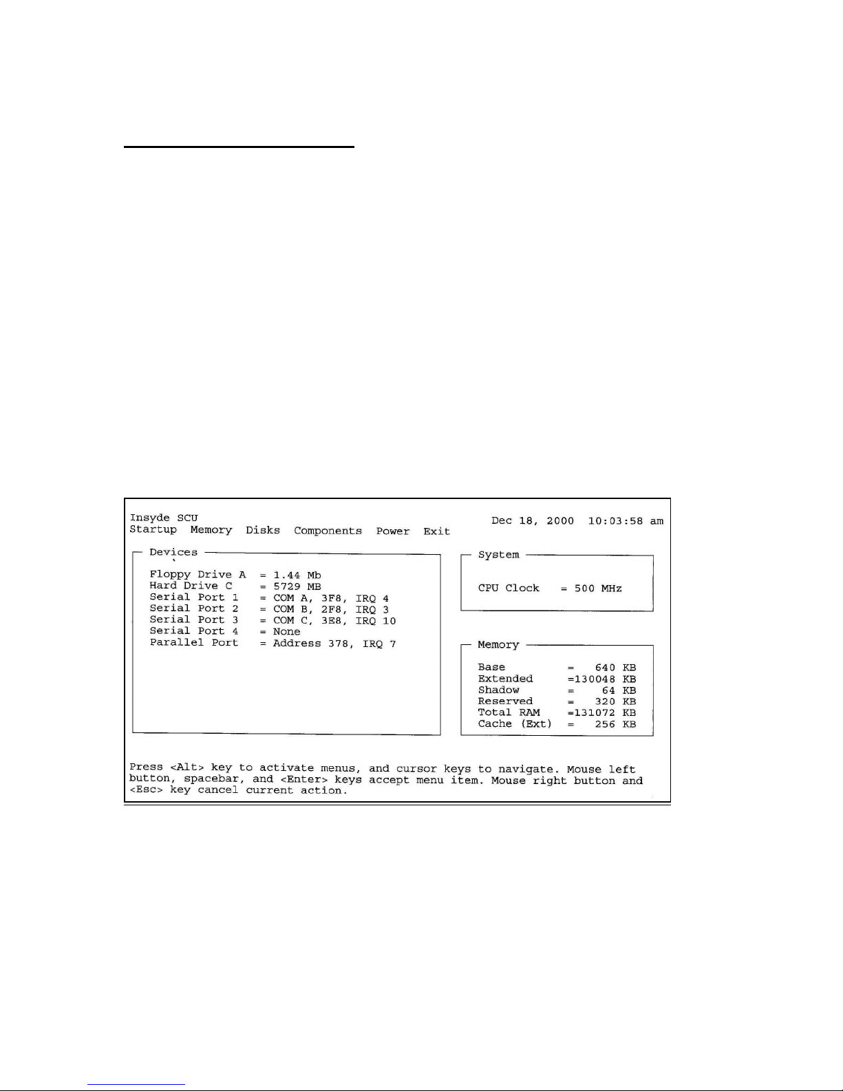
The Main setup page of the Setup Utility, illustrated below, allows you to change the
following information:
October 2001 Page 29 P/N 96-000001-017, Version Q301
Page 30
·
October 2001 Page 30 P/N 96-000001-017, Version Q301
Page 31
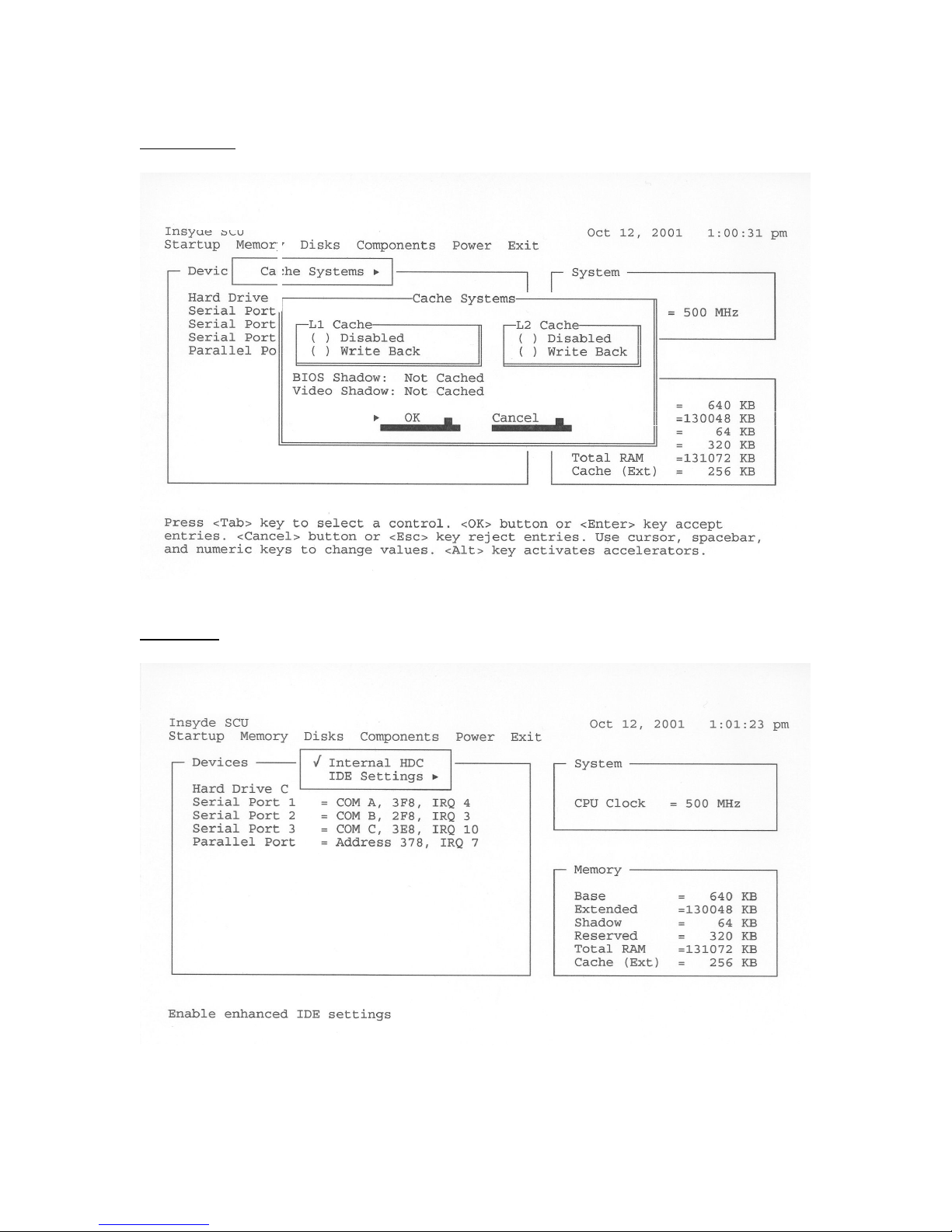
Memory Menu
· ·
Disks Menu
October 2001 Page 31 P/N 96-000001-017, Version Q301
Page 32
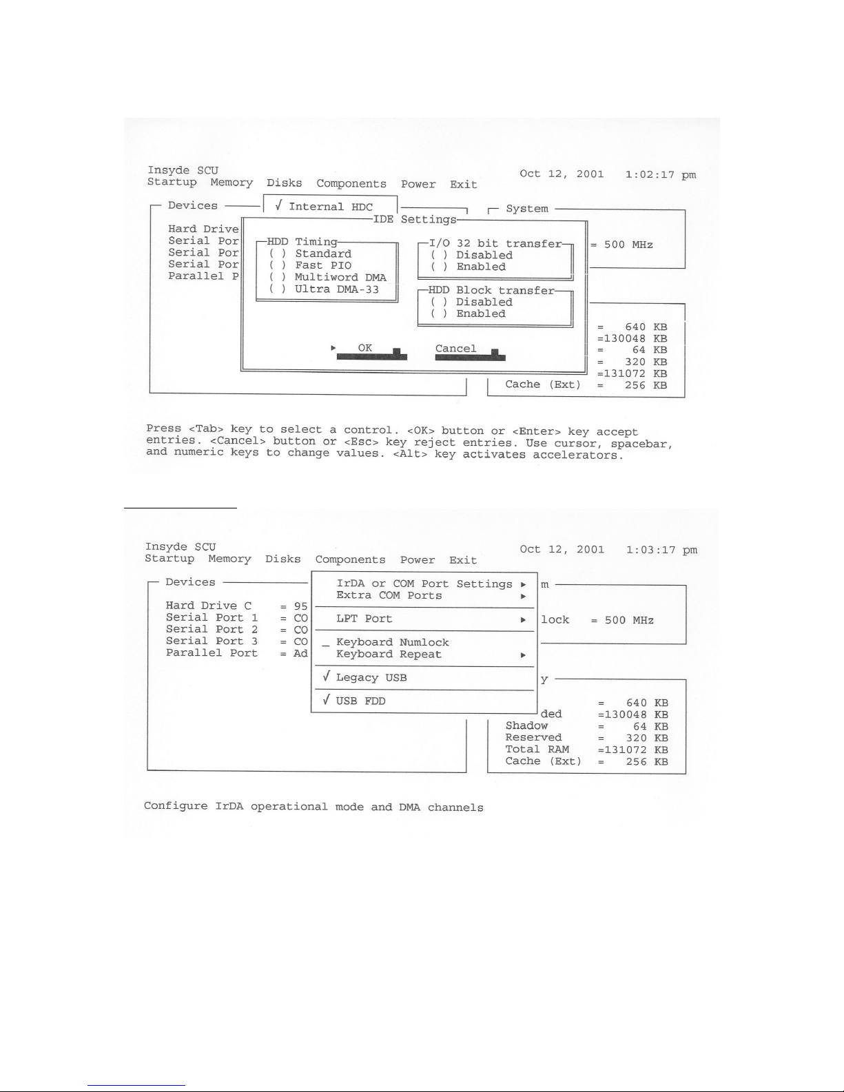
Components Menu
· · ·
October 2001 Page 32 P/N 96-000001-017, Version Q301
Page 33
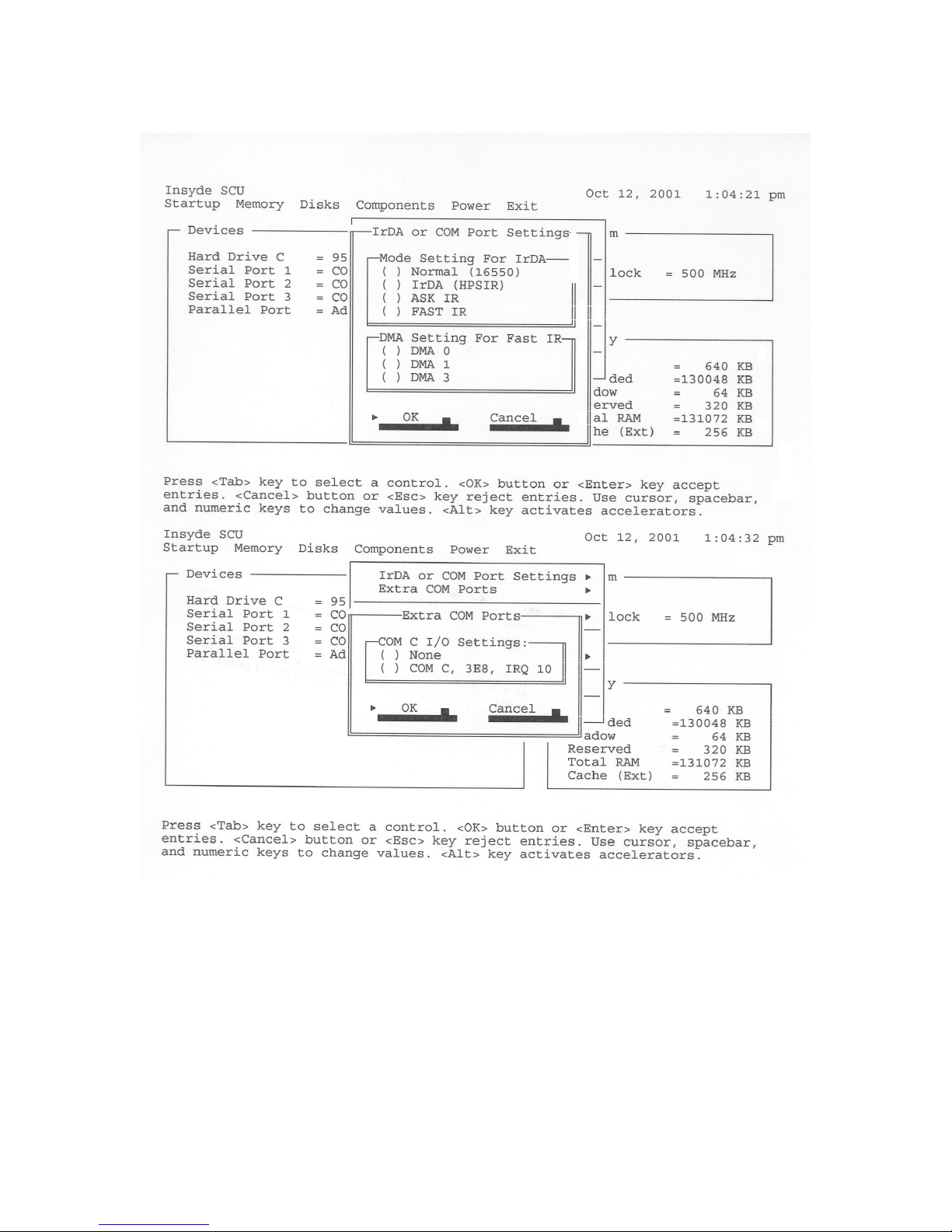
· · ·
October 2001 Page 33 P/N 96-000001-017, Version Q301
Page 34
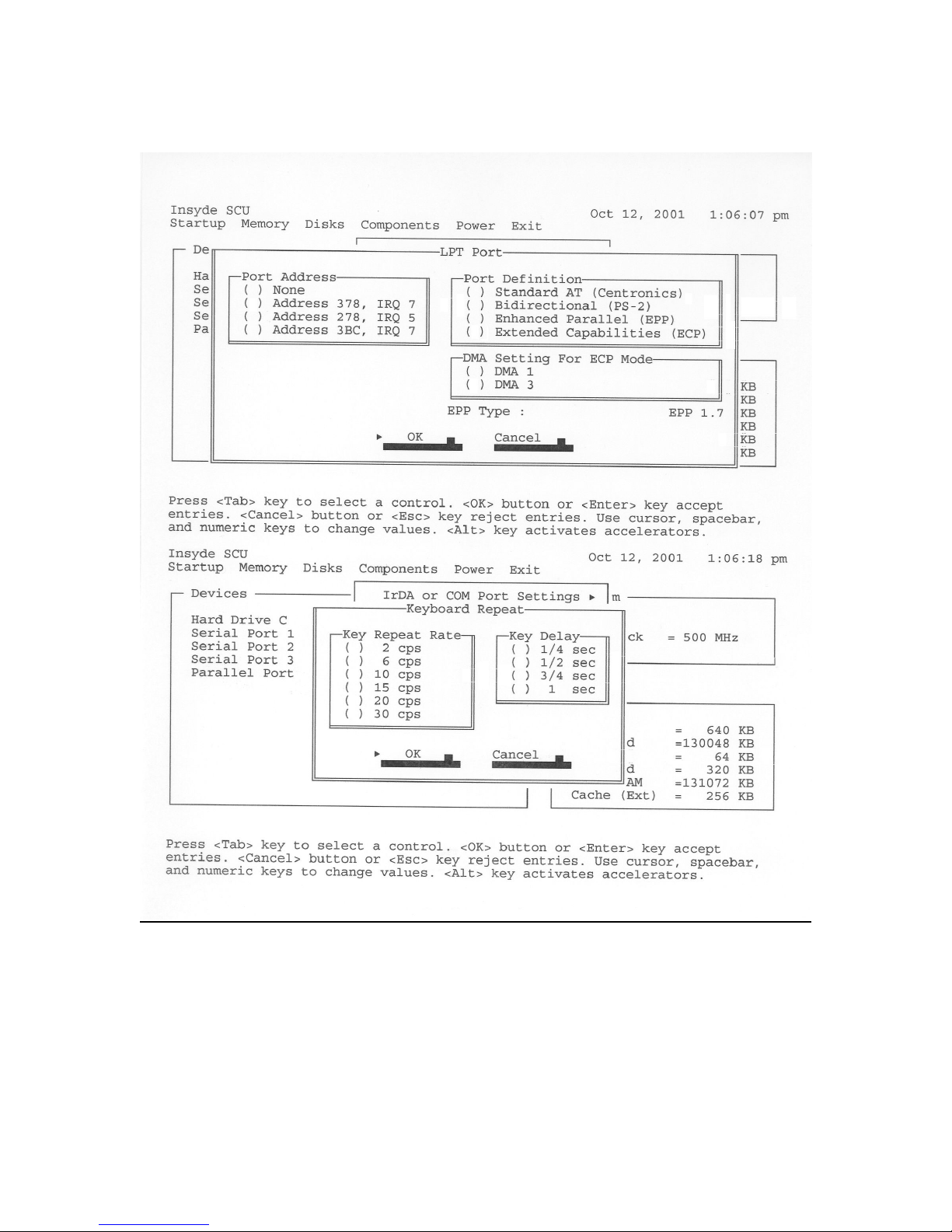
· ·
· ·
·
October 2001 Page 34 P/N 96-000001-017, Version Q301
Page 35
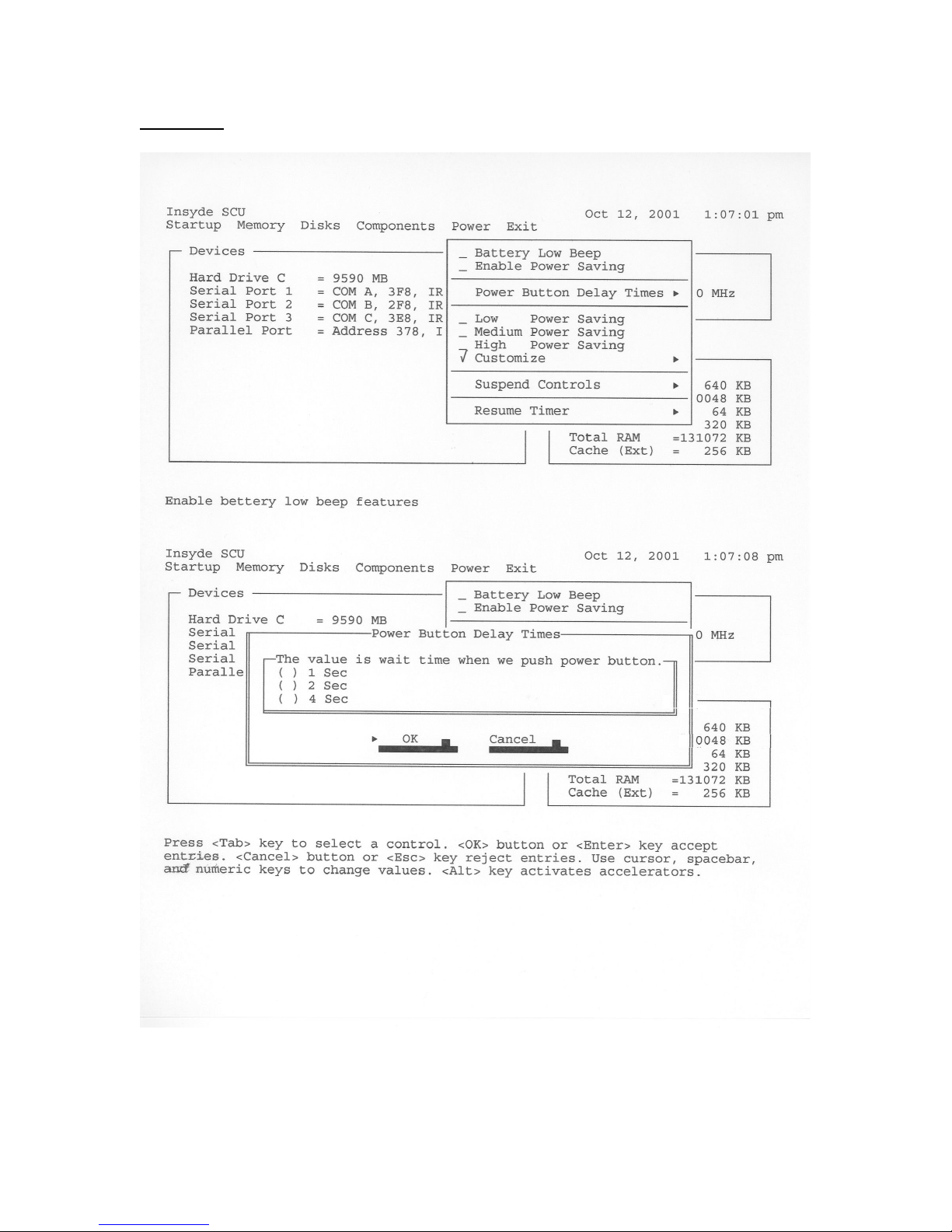
Power Menu
·
October 2001 Page 35 P/N 96-000001-017, Version Q301
Page 36
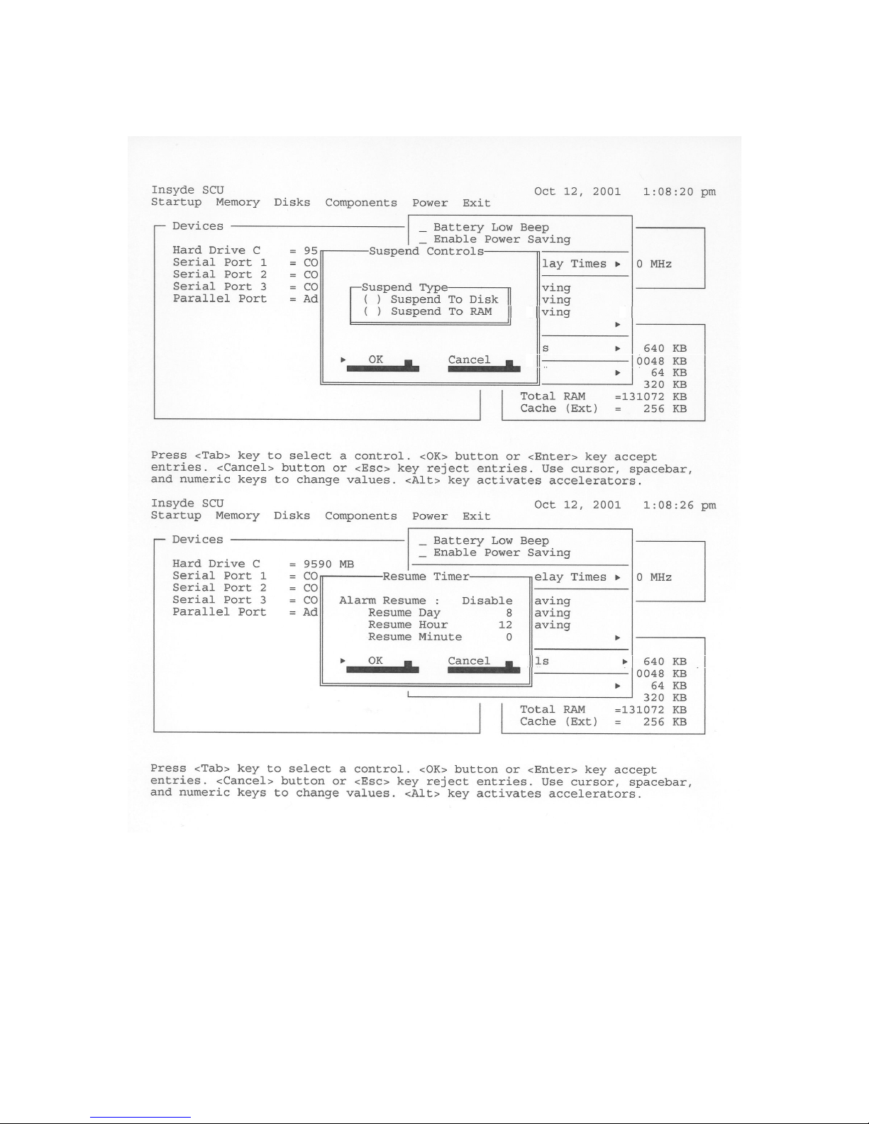
·
October 2001 Page 36 P/N 96-000001-017, Version Q301
Page 37
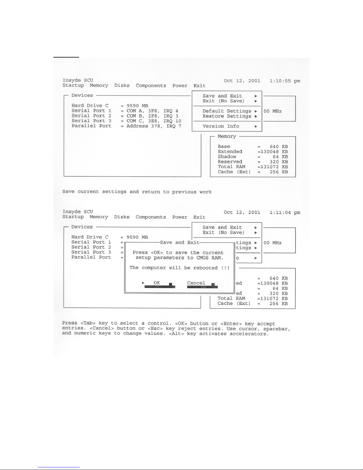
Exit Menu
October 2001 Page 37 P/N 96-000001-017, Version Q301
Page 38
October 2001 Page 38 P/N 96-000001-017, Version Q301
Page 39
October 2001 Page 39 P/N 96-000001-017, Version Q301
Page 40
October 2001 Page 40 P/N 96-000001-017, Version Q301
Page 41

Appendix B
Care and Maintenance
This appendix provides you with informatio n on how to maintain the GeneSys computer in top
working condition.
Maintenance
The GeneSys computer requires little physical maintenance. As with any piece of electrical
equipment, however, you should follow a few simple maintenance routines and
precautions so that your GeneSys can provide outstanding performance for many years to
come.
• Check the AC and DC power cords and power connectors periodically for damage. Replace
the power cord immediately if damage is found.
Keeping the Computer from Being Damaged
• Avoid scratching the surface of the screen with sharp objects.
• Your GeneSys computer is designed to sustain a multiple axis drop to a non-yielding surface.
However, please do not intentionally drop your GeneSys as the cumulative effect of
multiple drops may damage your computer.
• Do not place anything heavy on your GeneSys computer.
• Do not disassemble the computer.
• Remove the battery pack and keep it in a cool place if you will not be using the computer for
a long period of time.
• Insert a diskette straight into the external diskette drive. Inserting it at an angle can damage
the front of the external diskette drive.
• Keep the GeneSys computer at least 5 inches (13 cm) away from any electrical appliance
that generates a strong magnetic field such as a motor, magnet, TV, refrigerator, or large
audio speakers.
Cleaning Your GeneSys
Housing
Apply a small amount of mild cleaning solution to a dry, lint-free cloth and wipe the
housing with the cloth.
Screen
In order to maintain optimum performance between the pen and digitizer you should keep your
screen clean. This can be accomplished by lightly spraying isopropyl alcohol onto the screen and
wiping with a soft cloth or paper towel.
NOTE: Do not use any harsh chemicals to clean the screen as this may affect the performance of
your digitizer.
October 2001 Page 41 P/N 96-000001-017, Version Q301
Page 42

Detailed Product Specification
Super Rugged Construction
The GeneSys has been engineered for the most demanding applications. Extreme environments, high
mobility or specific application challenges are met by Xplore’s innovative and patented designs.
• Magnesium alloy case with impact resistant design
• Patented industrial grips or bumper protection system protects internal electronics
• Sealed and gasketed enclosure provides maximum security
• Award winning industrial and mechanical design- ideal for portable applications
• Size: 12.0" (305 mm) x 9.0" (229 mm) x 1.5" (38 mm) (WxHxD)
• Weight: 5.0 lbs. (2.27 kg)
• Proprietary thermal management system
Ultra Hi-Brite Color LCD Display and Enhanced Video
The brightest color LCD in the rugged pen tablet industry. Can be viewed in ALL lighting conditions
including direct sunlight, dim or intense florescent lighting. Advanced video memory and graphics
capabilities result in superior visual multimedia.
• 10.4" TFT SVGA color LCD for the GeneSys II and 12.1” Active Tr ansflective color LCD for the
GeneSys Maximus
• 800 x 600 resolution
• Display control ATI 3D RAGE LT PRO graphics accelerator
• 2x AGP Bus - 64 bit
• HW 3D graphics user interface
• 8 MB SGRAM video memory is standard
• An Xplore-designed main logic board using advanced technology results in a high performance,
very powerful mobile computing system.
• Intel® Pentium® III processor PIII 500 MHz with 256K L2 cache
• System memory options of 128 and 256 MB SDRAM
• Shock mounted hard disk options up to 20 GB
Powerful, Industry-Leading Performance
The most powerful rugged pen tablet in the industry and the first Pentium III 500 MHz!
• Intel Pentium III @ 500 MHz
• 256 KB internal L2 pipeline burst cache
• 128 or 256 MB of DRAM, 3.3 V, self refreshing, low power DIMM
• Hard disk size 10 or 20 G 2.5" ultra DMA shock & vibration damped HDD
Flexible Wireless (WAN/LAN) Capabilities
Factory integrated PC Card slots allow for virtually unlimited wireless expansion. A wide variety of
wireless Wide Area and Local Area Network options exist using current and emerging wireless
technologies.
• 2x Type II or 2x Type III PC Card slots internal to the GeneSys II
• Performance-matched antennas and shielded cabling
• CardBus support
• Current support for CDPD, Spread Spectrum, GPS, more. As new wireless technologies emerge,
the GeneSys II will support their integration.
Extended Portable Power
Smart Lithium-Ion Battery technology results in extended battery life while away from the AC/DC,
vehicle or desktop docking stations, which power and charge the battery. Ideal for highly mobile
applications.
• Up to 4 hours typical operating time for the GeneSys II and up to 6 hours for the GeneSys
Maximus– actual operating time depends on power management modes
• Power input 10 - 20 VDC
• Battery charging input power 20 VDC
• Li-Ion Power Smart Battery
• Integrated Smart Battery Charger. Max rate: 1000 mA/h with 20 VDC external power source
• ACPI v1.1 Power Management – Full Operation, Doze, Sleep and Suspend modes
• Batteries recharge (fast) in Tablet or Docking Stations
Protected Onboar d Connectors and Ports
One of the most flexible, rugged pen tablet computers with a wide range of onboard connectors in a
sealed and durable portable computer.
• IrDA Data Port (v1.1) – FIR-4Mbps/SIR-115.2Kbps as option
• 2x USB – Integrated USB type A connect ors
Multiple Input Options and Controls
Highly responsive and technologically advanced touch/pen digitizer represents the primary input
method. Additional input options are supported through an extensive membrane switch panel, external
rugged keyboards, mice and voice.
• Touch Screen – resistive touch screen - touch/pen operation
• Hard coated polyester top cover
• Extensive LED indicators on the main membrane panel:
o Docking Status Indicator
o Charging status of Battery
o Power Indicator
o HDD Activity
• Membrane Panel Keys Include:
o Power On/Off/Reset
o Brightness Controls Up and Down
o “Lights Out” Control Key for immediate backlight shutdown
o Emergency Call Button
o 1 Programmable Hot Key
o External rugged backlit keyboard, ideal for in-vehicle applications.
Superior Audio Quality
Enhanced audio technologies result in high quality audio output.
• 3D positional stereo surround support – via external speaker system
• ESS Allegro – 1 PCI audio accelerator
• Sound Blaster Pro compatible (external audio)
• Mic-in & Stereo Line-out via 3.5 mm JACK connector in Quick Release Plus Docks
Variety of Supporting Software Options
A range of operating systems, combined with various supporting software programs, provides maximum
flexibility depending on each user’s specific requirements.
• Operating Sys tems: Windows ® 98, Windows ® 2000 Professional, Windows ® NT 4.0 Workstation,
consult Xplore Technical Support for other OS
Appendix C
• CIC PenX v2.01 Pen Services
• On-Screen keyboard
• Industry standard Plug & Play BIOS, flash upgradeable
GeneSys XPanders – Expand Connectivity
Xplore’s Xpander and Xpander Plus can be attached to the GeneSys II Computer to provide a vast array
of expansion options. XPander provides external connectivity via:
• 1x RS232 Port
• 2x USB Ports
• PS/2 keyboard and PS/2 mouse ports
• DC Power Jack in
• XPander Plus provides additional connectivity with:
o PC Card Slot (2T2 or 1T3)
o 1x Parallel (EPP/ECP)
o 1x Additional RS232 Ports (total of 2)
o External dual speaker and mic capabilities in support of voice activation and sound output
applications – RCA Jacks
o External CRT port
Durable and Reliable Family of Quick Release Docking Stations
Xplore’s Quick Release (QR) Docking Systems are ideally suited for applications that require multiple
docking and undocking actions. Docking systems are available for vehicle, mo bile communication carts,
forklifts, service bays and other challenging docking environments.
• Quick dock and undock function result in an easy -to-use and user friendly option
• Formed stainless steel construction
• Tilt/Swivel functions for use from either side of the vehicle
• Connection points on the QR Dock Heads include:
o 1x RS232 Port
o 2x USB Ports
o PS/2 keyboard and PS/2 mouse ports
o DC Power Jack in
o XPander Plus provides additional connectivity with:
§ PC Card Slot (2T2 or 1T3)
§ 1x Parallel (EPP/ECP)
§ 1x Additional RS232 Ports (total of 2)
§ External dual speaker and mic capabilities in support of voice activation and sound
output applications – RCA Jacks
• The GeneSys II QR Docks mount to a variety of 3rd party mounting posts that have been
customized for specific markets.
Service Warranty
• Manufactured under strict ISO quality standards
• One year warranty included for GeneSys II and 3 year warranty for GeneSys Maximus
• Extended warranties available
• Range of professional services
Options
• AC/DC Power Supply 100 - 240 VAC international
• External battery charges, printers, bar code scanners, finger print readers, magnetic card readers
• Carrying Cases
• External USB 24x CR-ROM
• Cigarette Lighter Adaptor
• External USB 1.44MB floppy disk drive
Environmental Specific ation
• Temperature: According to MIL-STD 810 F, Method 514.1
• Humidity: According to MIL- STD 810 F, Method 507.4
• Altitude: Accord ing to MIL-STD 810 F, Method 500.4
• Shock: According to MIL-STD 810 F, Method 516.5
• Vibration: According to MIL-STD 810 F, Method 514.5
• Enclosure Class (rain and dust):
• Radiation:
• Approvals
Xplore Technologies and GeneSys are registered trademarks of Xplore Technologies Corporation of America. All trademarks
acknowledged. Our policy is continuous development and improvement. We therefore reserve the right to alter technical data
without notice. Xplore Commitment to Excellence.
§ External CRT port
o Operating Temp: –25º to +60º C (-4º to 140º F)
o Storage Temp: –40º to +75º C (-40º to 167º F)
o 5% to 95% RH, Non- condensing
o 15,000 ft. operating
o 40,000 ft. storage, altitude change rate: 2,000 ft./min
o Operating: 30 g, 11 ms, sawtooth wave
o Non-operating: 40 g, 11 ms, sawtooth wave
o Operating
: Category 20, Ground Vehicle Test
: Figure 514.5 C-3 Composite Wheeled Vehicle
: 5-500 Hz Random
: 2.18g rms (vertical)
: 1.60g rms (transverse)
: 1.96g rms (longitudinal)
o Non-Operating
: Category 24, Basic Integrity Test
: Figure 514.5 C-17 (8g rms random)
: 0.04 g2/Hz, 20-1000 Hz
: -6 dB/active 1000 – 2000 Hz
o According to MIL-STD 810 F, Method 506.4
§ Nema 3
§ IP 54
§ 4”/hr rate @ 40 mph
o FCC Part 15, Subpart B, Class B
o EMI: FCC Part 15 Class B
o CE Marking
October 2001 Page 42 P/N 96-000001-017, Version Q301
Page 43

Appendix D
Glossary
Abbreviations
AC: Alternating current MS-DOS: Microsoft Disk Operating
System
ANSI: American National Standards
Institute
APM: Advanced power management PCB: Printed circuit board
ASCII: American Standard Code for
Information Interchange
BIOS: Basic Input Output System PCMCIA: Personal Computer Memory
OCR: Optical character recognition
PCI: Peripheral component
interconnect
Card International Association
CD-ROM: Compact Disk-Read Only
Memory
CMOS: Complimentary metal-oxide
semiconductor
CPU: Central processing unit ROM: Read only memory
CRT: Cathode ray tube RTC: Real time clock
CLA: Cigarette lighter adapter SCSI: Small computer system
DC: Direct current SIO: Serial input/output
DDC: Display data channel SVGA: Super video graphics adapter
DOS: Disk operating system TFT: Thin-film transistor
DMA: Direct memory address UART: Universal asynchronous
ECP: Extended capabilities port USB: Universal serial bus
EGA: Enhanced graphics adapter VGA: Video graphics array
FDD: Floppy disk drive VRT: Voltage reduction technology
HDD: Hard disk drive
IDE: Integrated drive electronics
I/O: Input / output
IRQ: Interrupt request
KB: Kilobyte
LCD: Liquid crystal display
MDA: Monochrome display adapter
RAM: Random access memory
RGB: Red, green, blue
interface
receiver / transmitter
October 2001 Page 43 P/N 96-000001-017, Version Q301
Page 44

A
Adapter: a device that provides an interface between
two dissimilar electronic devices. For example, the AC
adapter modifies the power from a wall outlet for use by
the computer.
Advanced Power Management (APM): a facility
consisting of one or more layers of software that
support power management in computers with power
manageable hardware. The APM software interface
allows applications, operating systems, device drivers,
and the APM BIOS to work together to reduce power
consumption, without reducing system performance.
Alternating Current (AC): electric current that
reverses its direction of flow at regular intervals.
Analog Signal: a signal whose characteristics such as
amplitude and frequency vary in proportion to (are an
analog of) the value to be transmitted. Voice
communications are analog signals.
Application Program: a program that performs
specific tasks on your computer, such as word
processing or creating spreadsheets.
ASCII: American Standard Code for Information
Interchange. ASCII code is a set of 256 binary codes
that represent the most commonly used letters,
numbers, and symbols.
Asynchronous: lacking regular time relationship. As
applied to computer communications, asynchronous
refers to the method of transmitting data that does not
require a steady stream of bits to be transmitted at
regular time intervals.
ATA PC Card: a PC Card with an AT attachment hard
disk drive interface such as a storage device PC Card.
AUTOEXEC.BAT: a batch file that executes a series of
MS-DOS commands and programs each time you start
the computer.
B
Backup: a duplicate copy of files kept as a spare in
case the original is destroyed.
Batch File: a file that can be executed from the system
prompt containing a sequence of operating system
commands or executable files. See also
AUTOEXEC.BAT.
Binary: the base two number system composed of
zeros and ones (off or on), used by most digital
computers. The rightmost digit of a binary number has
a value of 1, the next a value of 2, then 4, 8, 16, and so
on. For example, the binary number 101 has a value of
5.
BIOS: programs that contain such basic hardware
operations as an interaction with diskette drives, hard
disk drives, and the memory.
Bit: a binary digit, representing the smallest unit of data
used by a computer.
Board: a circuit board. An internal card containing electronic
components called chips, which perform a specific function or
increase the capabilities of the system.
Boot: to load a program or operating system into system
memory.
BPS: bits per second. In serial transmission, the instantaneous
bit speed with which a device or channel transmits a character.
Buffer: the portion of the computer’s memory where data is
temporarily stored. Buffers often compensate for differences in
the rate of flow from one device to another.
BUS: an electrical circuit within the system, used to transmi t
signals, data or electric power.
Byte: a group of eight contiguous bits.
C
Cache Memory: high speed memory which stores data that
increases processor speed and data transfer rate. When the
CPU reads data from main memory, it stores a copy of this data
in cache memory. The next time the CPU needs that same
data, it looks for it in the cache memory rather than the main
memory, which saves time. The computer has two cache levels.
Level one is incorporated into the processor and level two
resides in external memory.
Card: synonym for board, see board.
CardBus: an industry standard bus for 32-bit PC Cards.
Capacity: the amount of data that can be stored on a magnetic
storage device such as a diskette (floppy disk) or hard disk. It is
usually described in terms of kilobytes (KB), where one
KB=1024 bytes and megabytes (MB), where one MB=1024 KB.
CD-ROM: a Compact Disk-Read Only Memory stores data on
metal-plated plastic discs. Your GeneSys® computer can read
such disks that have been pre-recorded in a variety of standard
formats.
Chip: a small semiconductor containing computer logic and
circuitry for processing, memory, input/output functions and
controlling other chips.
Clock: an electrical timer, used to synchronize system
operations.
CMOS: a special type of low-power memory that records and
stores information about your computer’s configuration. CMOS
is not erased when you power off the computer.
Cold Start: starting a computer that is currently off (turning on
the power).
COMx: the alias that the operating system and software
applications use to identify serial ports, where x refers to the
number of the port.
Command: an instruction you issue to direct the actions of the
computer or its peripheral devices.
Communications: the means by which a computer transmits
and receives data to and from another computer or device. See
parallel interface; serial interface.
October 2001 Page 44 P/N 96-000001-017, Version Q301
Page 45

Compatibility: 1) the ability of one computer to accept
and process data in the same manner as another
computer without modifying the data or the media upon
which it is being transferred. 2) the ability of one device
to connect or communicate with another system or
component.
Components: elements or parts (of a system) which
make up the whole (system).
Computer Program: a set of instructions written for a
computer that enables it to achieve a desired result.
Computer System: a combination of hardware,
software, firmware, and peripheral components
assembled to process data into useful information.
Configuration: the specific combination of hardware
components of the computer, and their operating
status. The configuration of your computer includes pre defined memory, type and speed of microprocessor,
type of and size of hard disk drive, etc.
Controller: built-in hardware and software that controls
the functions of a specific internal or peripheral device
(e.g. digitizer controller)
Co-processor: a circuit built into the processor that is
dedicated to intensive math calculations.
Cursor: a small, blinking rectangle or line that indicates
the current position on the display screen.
D
Data: the information the system stores and processes.
Default: the parameter value automatically selected by
the system when you or the program do not provide
instructions. Also called a preset value.
Delete: to remove data from a disk or other data
storage device. Synonymous with erase.
Device Driver: a program that controls communication
between a specific peripheral device and the computer.
Diskette: a flat magnetic-coated material used to store
programs and data. Unlike a hard disk drive, which is
rigid, a diskette is flexible and therefore often referred to
as a “floppy” disk.
Disk Drive: the physical device that allows the system
to read from, and write to, a disk. A floppy disk drive
allows you to insert and remove diskettes, while a hard
disk drive is permanently sealed inside a disk drive.
Display: a CRT, plasma screen, LCD, or other image
producing device used to view computer output.
Documentation: the set of manual and/or other
instructions written for the users of a computer system
or application. Computer system documentation
typically includes procedural and tutorial information as
well as system functions.
Double-tap: to press and release the pen/stylus twice
within a time frame defined by the user, without moving
the pointer off the choice.
Driver: software that allows an application program to
communicate with a particular piece of equipment, such as a
printer or the pen/stylus.
E
Expanded Memory: special additional memory designed to
extend the 640KB limit imposed by DOS, and recognized by
many, but not all, DOS application programs.
Extended Memory: memory beyond the first 1 MB of memory
recognized by DOS.
F
File: a collection of related information; a file can contain data,
programs, or both.
Firmware: a set of instructions built into the hardware which
controls and directs the microprocessor’s activities.
Floppy Disk: see diskette.
Floppy Disk Drive(FDD): an electromechanical device that
reads and writes to floppy disks.
Format: the process of readying a blank disk for its first use.
Formatting establishes the structure of the disk that the
operating system expects before it writes files or programs onto
the disk.
Folder: an icon Windows uses to store documents or other
folders.
H
Hard Disk Drive (HDD): a sealed mass storage device used for
storage and fast retrieval of programs and data. The factory
installs this disk and only a trained engineer can remove it for
servicing.
Hardware: the physical electronic and mechanical components
of a computer system: typically, the computer itself, CPU,
memory, etc.
Hertz: a unit of wave frequency that equals one cycle per
second.
Host Computer: the computer that controls, regulates, and
transmits information to a device or another computer.
I
Icon: a small graphic image displayed on the screen or in the
indicator panel. In Windows, an icon represents an object that
the user can manipulate.
Instruction: statements or commands that specify how to
perform a particular task.
Interface: 1) hardware and/or software components of a
system used specifically to connect one system or device to
another. 2) to physically connect one system or device to
another to exchange information. 3) the point of contact
between user, the computer, and the program (e.g. the
pen/stylus or a menu).
October 2001 Page 45 P/N 96-000001-017, Version Q301
Page 46

Interrupt Request (IRQ): a signal that gives a
component access to the processor.
I/O: refers to acceptance and transfer of data to and
from a computer.
I/O Devices: equipment used to communicate with the
computer and transfer data to and from it.
Modem: a device that connects your computer to a telephone
line, allowing it to communicate with another computer at
another location.
Motherboard: a name sometimes used to refer to the main
printed circuit board in processing equipment. It usually
contains integrated circuits that perform the processor’s basic
functions and provides connectors for adding other boards that
perform special functions. Sometimes called a main logic board.
J
Jumper: a small clip or wire that allows you to change
the hardware characteristics by electrically connecting
two points of a circuit.
K
Keyboard: an input device containing switches that are
activated by manually pressing marked keys. Each
keystroke activates a switch that transmits a specific
code to the computer.
Kilobyte (KB): a unit of 1024 bytes measuring storage
space, typically in memory or on storage media such as
a diskette or hard disk drive.
L
LAN: local area network. Assembly of separate
computers into an integrated network which connects
the various computers together and to common devices
such as printers, fax machines, etc…
Light Emitting Diode (LED): a semiconductor device
that emits light when a current is applied.
Liquid Crystal Display (LCD): liquid crystal sealed
between two sheets of glass coated with transparent
conducting material. Applying a voltage between the
glass sheets darkens the liquid crystal to provide
contrast to lighted portions of the display.
Lithium-ion Battery: a type of rechargeable battery
pack that your computer can support.
M
Main Logic Board (MLB): see motherboard.
Megabyte (MB): a unit of data storage equal to 1024
kilobytes.
Megahertz: a unit of wave frequency that equals 1
million cycles per second.
Menu: a software interface that displays a list of options
on the screen.
Microprocessor: a hardware component contained in
a single integrated circuit that carries out instructions.
Also called the central processing unit (CPU), one of
the main parts of the computer.
Mode: a method of operation, for example, the boot
mode or the resume mode.
N
Non-system Disk: a formatted diskette (floppy disk) you can
use to store programs and data but you cannot use to start the
computer. See system disk.
Nonvolatile Memory: usually read-only (ROM) that is capable
of permanently storing information. Turning the computer’s
power off does not alter data stored in nonvolatile memory.
O
On-line State: a functional state of a peripheral device when it
is ready to receive or transmit data.
Operating System: a group of control programs that direct the
internal operation of a computer.
Output: the results of a computer operation. Output commonly
indicates data 1) printed on paper, 2) displayed at a terminal, 3)
sent through the serial port or internal modem, 4) stored on
some magnetic media.
P
Parallel: refers to two or more processes or events that can
occur simultaneously, and without interfering with each other.
Parallel Port: a type of interface through which data is
transferred in groups data bits (binary units).
Partition: a logical unit created on a hard disk drive, which
appears to the operating system as a separate drive.
Password: a unique string of characters used to identify a
specific user. The computer provides various levels of password
protection.
PC Card: a plug-in accessory card that conforms to the
PCMCIA standard.
PCI Bus: a means for connecting devices to a computer which
is electrically coupled to and operates at the same speed as the
microprocessor’s external clock.
Pen: see stylus.
Peripheral Device: an I/O device that is external to the central
processor and/or main memory such as a printer or scanner.
Pixel: picture elements (tiny dots) that compose a screen
image.
Port: the electrical connection through which the computer
sends and receives data to and from devices or other
computers.
Printed Circuit Board: a hardware component of a processor
to which integrated circuits and other components are attached.
October 2001 Page 46 P/N 96-000001-017, Version Q301
Page 47

The board itself is typically flat and rectangular, and
constructed of fiberglass, to form the attachment
surface.
Power-on Self Test: a diagnostic program the
computer performs automatically whenever it is
powered on or reset.
Program: a set of instructions a computer can execute
to tell the system what to do and how to do it.
Prompt: a mes sage the computer provides indicating it
is ready for or requires information or an action from
you.
R
Random Access Memory (RAM): a hardware
component of your computer that temporarily stores
active program code and data.
Reset: that act of reloading the operating system.
Resolution: the number of pixels displayed on the
screen. A higher resolution provides greater clarity and
allows more information to be displayed on the screen
at once.
Restart: resetting a computer without turning it off (also
called warm boot or soft reset).
Resume: a return to active, operational state of the
system.
ROM: the portion of your computer’s memory that
contains permanent instructions, and which cannot be
modified.
RS-232: the Electronic Industries Association (EIA)
interface standard that describes the connector
interface and control, data, and status signals that allow
asynchronous communications between computers,
printers, communications and other peripheral devices.
Super VGA: a video interface which offers higher resolution
and/or deeper color depths than standard VGA.
Suspend Mode: a power conservation mode in which electrical
current is removed from most components of the system.
Synchronous: having a constant time interval between
successive bits, characters or events.
System Disk: a disk, which contains the core, files of an
operating system, and which can boot the operating system.
T
TFT: a color LCD technology that applies individual transistors
to each pixel enabling fine dis play control and excellent screen
legibility.
U
Universal Serial Bus: this serial interface lets you
communicate with several devices connected to the computer.
V
VGA: video graphics array is an industry standard video
adapter that lets you run any popular software.
Volatile Memory: random access memory that stores
information as long as the computer is powered and operating.
W
Warm Start: restarting or resetting a computer without turning it
off.
Window: a portion of the screen that can display its own
application or document.
Write-protection: a method for protecting a diskette (floppy
disk) from accidental erasure.
S
SCSI: small computer system interface is an industry
standard interface for connection of a variety of
peripheral devices.
Serial Interface: a type of interface through which data
is transferred one bit, or binary unit, at a time.
Serial Port: a communications port to which you can
connect devices, such as a modem, mouse, or serial
printer.
Software: the set of programs, procedures and related
documentation associated with a computer system.
Specifically refers to computer programs that direct and
controls the computer system’s activities.
Status In dicator (LED): a light above the LCD screen
which indicates the current status of a particular device
or hardware component.
Stylus: a writing instrument. For pen computers, the
stylus is used to interface with the LCD and digitizer.
October 2001 Page 47 P/N 96-000001-017, Version Q301
X
Y
Z
Page 48

October 2001 Page 48 P/N 96-000001-017, Version Q301
 Loading...