

Page 1
Do’s and Don’ts.Do’s and Don’ts.
Do read all the instruction leaflet before commencing installation.
Do install each fan with a double pole-isolating switch.
Do make sure the mains electricity supply is switched off before attempting to make
electrical connections or carry out any maintenance or cleaning.
Guarantee
Customers outside UK - see international below.
UK: The fan is guaranteed against defects for 3 years from date of purchase.
Please keep you purchase receipt.
If you have any problems, contact Xpelair’s Head Office at address shown below.
Technical advice and serviceTechnical advice and service
Customers outside UK - see international below.
UK: Xpelair have a comprehensive range of services including:
Free technical advice help-desk from Engineers on all aspects of ventilation.
Free design service, quotations and site surveys.
Service and maintenance contracts to suit all requirements.
Please ask for details:
By telephone on Techline: +44(0) 8709 000430
By fax on Techfax: +44(0) 8709 000530
At the address below
International
Guarantee - Contact your local distributor or Xpelair direct for details.
Technical advise and service - Contact your local Xpelair distributor.
R
R
Applied Energy Products Ltd
Morley Way
Peterborough
PE2 9JJ
t 01733 456789
f 01733 310606
www.applied-energy.com
Xpelair is a registered trademark of Applied Energy Products Limited.
Applied Energy Products reserve the right to alter product specifications
or appearance without prior notice. All finishes and diagrams in this
booklet are as accurate as printing processes allow.
Leaflet Part No. 22750AA (Revision C)
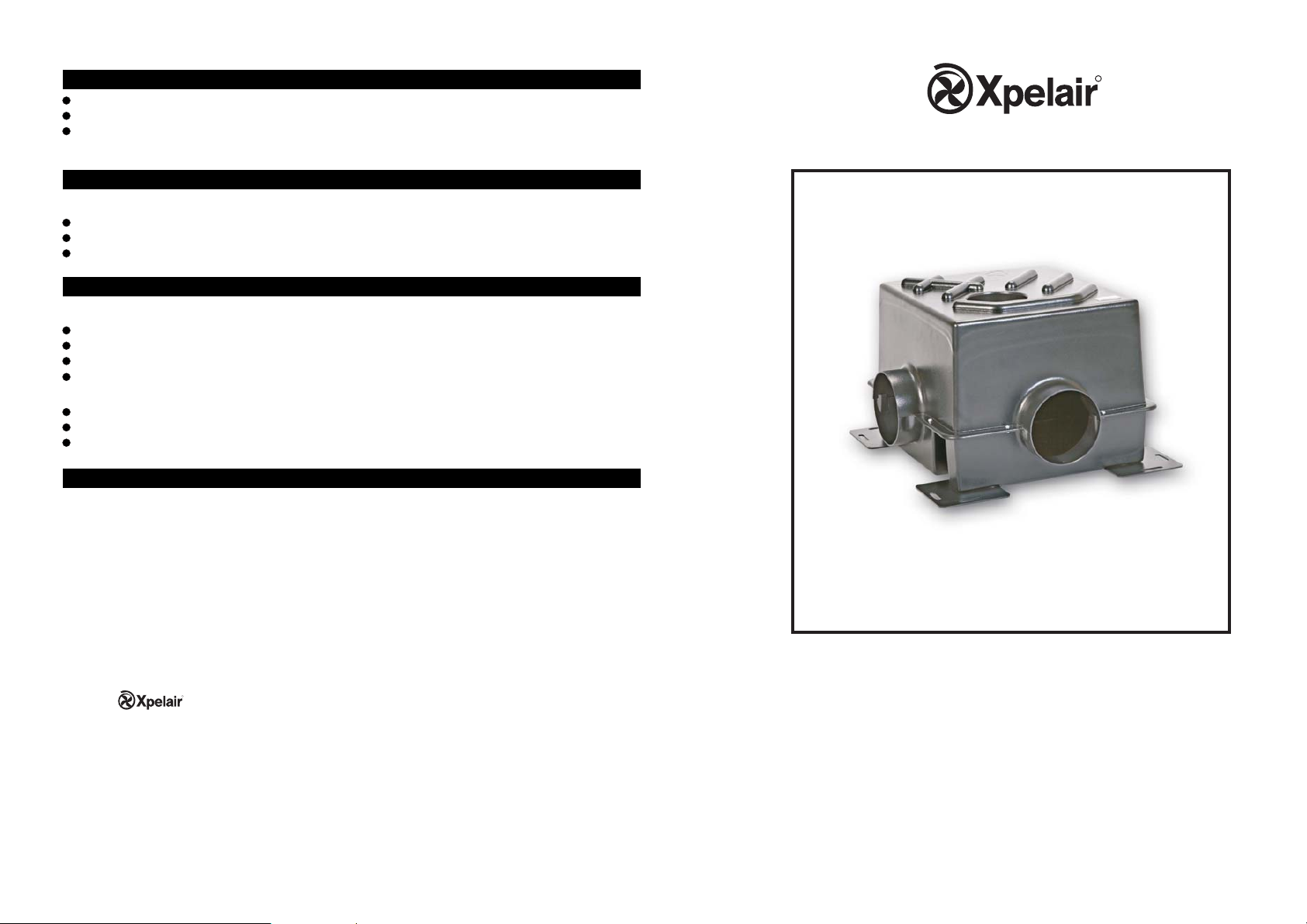
Xplus multipoint
ventilation unit
Xplus 275
Page 2
Xpelair Multipoint ventilation unit
Installation and Operating Instructions
PLEASE LEAVE THIS LEAFLET WITH THE FAN,
FOR THE BENEFIT OF THE USER
Installing the fanInstalling the fan
These products are intended for
connection to fixed wiring.
Check that the electrical rating shown
on the products matches the mains
supply.
WARNING: THIS PRODUCT IS FOR
CONNECTION TO 1 PHASE SUPPLY
ONLY, DO NOT CONNECT TO
3 PHASE SUPPLY.
WARNING: THIS APPLIANCE MUST
BE EARTHED.
All installations must be supervised
by a qualified electrician.
Installation and wiring must conform
to current IEE regulations (UK), local
or appropriate regulations
(other countries).
If there is damage to the fitted lead
this must be replaced by the
manufacturer or service agent.
If you have any queries before
installing these products or after they
are installed, call the
Xpelair Technical Hotline +44 (0) 8709
000430. Our engineers are there to
help during normal office
hours (UK only) and may be faxed at
all other times on +44 (0) 8709 000530.
Customers outside the UK please
contact your local Xpelair distributor,
details of which are available
from the UK office.
Description
Xplus 275
3 speed when used with an appropriate
controller (not supplied).
Extract only.
Suitable for continuous operation.
What the installer will needWhat the installer will need
A means for disconnection in all poles
must be incorporated in the fixed wiring in
accordance
Speed controller.
Suitably rated cable.
Ducting long enough to connect from the
position of the air intake positions of the
air outlet via the fan.
Ducting accessories, including internal
and external grilles and fasteners.
For flexible ducting, you will need
worm drive clips (available from Xpelair)
to attach the ducting to the fan inlets
and outlet.
If installing in a position where
condensation is likely to run back towards
the fan, you will need a suitable
condensation trap.
with the wiring regulations.
Where to locate itWhere to locate it
Position of air intake
As far as possible from and opposite
to the main source of air replacement
to ensure airflow across the room
(eg, opposite an internal doorway).
Near the source of steam or odours.
Not where ambient temperatures
are likely to exceed 50 C. or above
a cooker hob or eye level grill.
If installing in a room containing a
fuel burning device, it is the
installer’s responsibility to ensure
that there is enough replacement
air to prevent fumes being drawn
down the flue when the fan is
operating up to maximum extract.
Refer to Building Regulations for
specific requirements.
Exhaust air must not be discharged
into a flue used for exhausting
fumes from appliances supplied
with energy other than electric.
Requirements of all authorities
concerned must be observed for
exhaust air discharge.
When installed for use in possible
chemical corrosive atmospheres,
consult our Technical Service
Department. (For overseas markets
contact your local Xpelair
Distributor).
The inlet grilles should be situated
at least 0.5m distance from the
discharge outlet of a flued heating
or cooking appliance.
o
Position of the fan
The fan can be mounted to a suitably
strong wall or roof member.
Position of the air outlet
At least 0.5m away from open door or
window, or the inlet of another ventilation
device.
Installing the ductingInstalling the ducting
Detach the appropriate inlet covers
1.
after removing the fixing screws.
Note: do not detach cover from any
inlet not being used.
Install the ducting to connect the fan to
2.
the air intakes and to the outlet. If the
ducting is suspended, ensure that it is
adequately supported.
Fit intake and outlet grilles as required.
3.
If installing in a position where
4.
condensation is likely to run back
towards the fan, install a condensation
trap as near to the fan as possible.
Mounting the fanMounting the fan
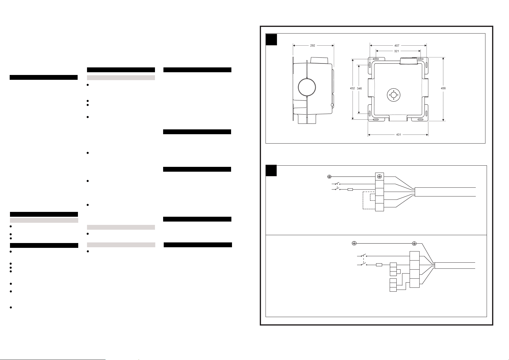
Mount the fan, using appropriate
1.
fasteners through the mounting
holes provided. For fan dimensions,
see Fig. A.
Attach the ducting over the inlets and
2.
outlet and secure it with worm
drive clips.
Connecting the fanConnecting the fan
Switch off the mains electrical supply
1.
and remove fuses.
Wire the fan as shown in fig. B.
2.
Connect the cable from the isolating
3.
switch to the electrical supply wiring.
Refit fuse before turning on the
4.
electricity supply.
Note:
For fixed wiring circuits, the
protective fuse for the appliance must
not exceed 5A.
Connecting the fanConnecting the fan
The fan can be operated using the
1.
controller (not supplied). The fan has
3 speed settings:
High(H), Medium (M) and Low (L).
Cleaning
Before cleaning isolate completely from
1.
the mains supply.
Wipe the inlet covers carefully with
2.
a damp cloth.
Dry thoroughly.
3.
Never use solvents to clean.
4.
Apart from cleaning, no other
maintenance is required.
A
B
N
L
Xplus 275 WIRING INSTRUCTIONS
Xplus 275 WIRED THROUGH THE THREE SPEED SWITCH REF.91457AW
FUSE
DOUBLE POLE
ISOLATING SWITCH
LOW SPEED
HIGH
SPEED
LINK WIRES.
CONNECT TO
OBTAIN REQUIRED
SPEED
N
L
DOUBLE POLE
ISOLATING SWITCH
MEDIUM
SPEED
GREEN/YELLOW
BLUE
N
BROWN
L
BLACK
M
H
BLACK/WHITE
Link to obtain speeds as follows
L = Low Speed
L - M = Medium Speed
L - H = High Speed
FUSE
P
P
P
T1
T2
T3
SWITCH
TERMINALS
GREEN/YELLOW
N
L
M
H
CABLE FITTED TO FAN
BLUE
BROWN
BLACK
BLACK/WHITE
CABLE FITTED TO FAN
 Loading...