

XPEECH 2S, 2O, 4S, 4O, 2S2O Operation Manual
...

THE SPECIFICATIONS AND INFORMATION REGARDING THE PRODUCTS IN THIS MANUAL ARE
SUBJECT TO CHANGE WITHOUT NOTICE. ALL STATEMENTS, INFORMATION, AND
RECOMMENDATIONS IN THIS MANUAL ARE BELIEVED TO BE ACCURATE BUT ARE PRESENTED
WITHOUT WARRANTY OF ANY KIND, EXPRESSED OR IMPLIED. USERS MUST TAKE FULL
RESPONSIBILITIES FOR THEIR APPLICATION OF THE PRODUCTS.
THE SOFTWARE LICENSE AND LIMITED WARRANTY FOR THE ACCOMPANYING PRODUCT ARE SET
FORTH IN THE INFORMATION PACKET THAT IS SHIPPED WITH THE PRODUCT AND ARE
INCORPORATED HEREIN BY THIS REFERENCE.
NOTWITHSTANDING ANY OTHER WARRANTY HEREIN, ALL DOCUMENT FILES AND SOFTWARE OF
THESE SUPPLIERS ARE PROVIDED “AS IS” WITH ALL FAULTS. PRODUCT AND THE ABOVE-NAMED
SUPPLIERS DISCLAIM ALL WARRANTIES, EXPRESSED OR IMPLIED, INCLUDING, WITHOUT
LIMITATION, THOSE OF MERCHANTABILITY, FITNESS FOR A PARTICULAR PURPOSE AND
NONINFRINGEMENT OR ARISING FROM A COURSE OF DEALING, USAGE, OR TRADE PRACTICE.
IN NO EVENT SHALL THE PRODUCT OR ITS SUPPLIERS BE LIABLE FOR ANY INDIRECT, SPECIAL,
CONSEQUENTIAL, OR INCIDENTAL DAMAGES, INCLUDING, WITHOUT LIMITATION, LOST PROFITS
OR LOSS OR DAMAGE TO DATA ARISING FROM THE USE OR INABILITY TO USE THIS MANUAL, EVEN
IF THE PRODUCT OR ITS SUPPLIERS HAVE BEEN ADVISED OF THE POSSIBILITY OF SUCH
DAMAGES.
Operation Manual V2.9
COPYRIGHT ©2007 All rights reserved.

Contents
1. Introduction....................................................................................................1
Product Overview.........................................................................................................................................1
Hardware Description...................................................................................................................................2
2. Installation and Applications......................................................................13
Network Interface.......................................................................................................................................13
Telephone Interface Description................................................................................................................17
3. Setting the Gateway through IVR...............................................................20
IVR (Interactive Voice Response)..............................................................................................................20
IP Configuration Settings of WAN Port......................................................................................................23
4. Setting a Gateway with WEB Browser .......................................................26
Network Settings (WAN)............................................................................................................................27
Network Settings (LAN)..............................................................................................................................32
QoS Settings..............................................................................................................................................34
NAT/DDNS.................................................................................................................................................36
Caller ID .....................................................................................................................................................38
Telephony Settings.....................................................................................................................................40
SIP..............................................................................................................................................................46
Private Network..........................................................................................................................................53
Calling Features.........................................................................................................................................55
Advanced Options......................................................................................................................................57
Digit Map....................................................................................................................................................62
Phone Book................................................................................................................................................66
Caller Filter.................................................................................................................................................66
CDR Settings .............................................................................................................................................67
Language ...................................................................................................................................................67
Transit Call Control.....................................................................................................................................68
Long-Distance Control Table......................................................................................................................69
Long Distance Exception Table..................................................................................................................69
CPT/Cadence Settings...............................................................................................................................70
System Information....................................................................................................................................76
RTP Packet Summary................................................................................................................................77
STUN Inquiry..............................................................................................................................................77
Ping Test.....................................................................................................................................................77
NTP............................................................................................................................................................78
Backup/Restore..........................................................................................................................................78
Provision Settings ......................................................................................................................................79
System Operations.....................................................................................................................................80
Software Upgrade......................................................................................................................................81
Logout ........................................................................................................................................................81
5. IP Sharing Functions...................................................................................82
6. Coding Principle..........................................................................................86
Instruction...................................................................................................................................................86
Dialed Number Processing Flow................................................................................................................86
Example for Call Out via VoIP – Contents of Invite....................................................................................86
Example for Match phone numbers invited by callers...............................................................................87
7. Advanced Feature .......................................................................................89

Static Route................................................................................................................................................89
RIP (Routing Information Protocol)............................................................................................................89
Port filtering................................................................................................................................................90
IP Filtering..................................................................................................................................................90
MAC Filtering..............................................................................................................................................91
Virtual Server .............................................................................................................................................91
DMZ............................................................................................................................................................91
URL Filter...................................................................................................................................................92
Special Applications................................................................................................................................... 92
DoS Prevention Settings............................................................................................................................93
8. VPN IPSEC ※ ..............................................................................................94
Notice................................................................................................................99

SIP Operation Manual
1
1. Introduction
Product Overview
The stand-alone VoIP Gateway carries both voice and facsimile over the IP network. It
supports SIP industry standard call control protocol to be compatible with free registration
services or VoIP service providers’ systems. It works in two different modes: UA (User Agent)
or Server. As a standard user agent, it is compatible to all well-known Soft Switches and SIP
proxy servers. While running the optional server software, the gateway can be configured to
establish a private VoIP network over the Internet without a 3
There are 3 types of gateways in the same series: 2 ports, 4 ports and 8 ports (voice ports,
FXS and/or FXO). The gateway can be seamlessly integrated to existing network by
connecting to a phone set, PBX, key telephone system, fax machine or PSTN line. With only a
broadband connection such as ADSL bridge/router, Cable Modem or leased line router, it
allows you to gain access to voice and fax services over the IP in order to reduce the cost of
international and long distance calls.
In addition, the in-built 4 ports Ethernet switch supports comprehensive Internet gateway
functions to accommodate other PCs or IP devices to share the same broadband stream. QoS
function allows voice and data traffic to flow through where voice traffic is transmitted in the
highest priority. With TOS bit enabled, it guarantees voice packets to have first priority to pass
through a TOS enabled router.
With the support of DDNS, it makes the gateway reachable by its domain name where the ISP
dynamically assigns the IP address. It helps users to host a web site or mail server in a PPPoE
or DHCP network. By enabling the CDR function & setting up a simple server, administrators
are allowed to log in and view all call records such as call duration, time and date of calls and
latency.
The gateway can be assigned with a fixed IP address or by DHCP, PPPoE. It adopts the G.711,
G.726, G.729A or G.723.1 voice compression format to save the network bandwidth while
providing real-time and toll quality voice. In addition, in the event that the power supply fails or
Internet connection is lost, the gateway can automatically divert the FXS end to the PSTN
network on the FXO port so users can still use the conventional PSTN line to make calls. This
feature is especially useful while dialing emergency calls (i.e. 911).
rd
party SIP Proxy Server.

2
A
Hardware Description
2 ports gateway model: 2S / 2O / 1S1O
Front Panel
VoIP Gateway
Power Indicator: Green light indicates a normal power supply.
Run Indicator: Blinking green light indicates normal operation.
WAN, LAN indicators Status indicatorsVoice ports indicators
L4 L3 L2 L1 WAN
P2 P1
SIP Operation Manual
larm RUN Power
Alarm Indicator: When the system starts up, the red light will blink. It also indicates the
gateway’s abnormal operation.
Voice ports indicators: Indicate connection and activity on the port 1 – 2.
WAN stands for the WAN Port Indicator.
L1 – L4 stands for the LAN Port Indicator.
When starting up the system, the Alarm, Run, and Power indicators will light up. Af ter about 40
seconds, the Alarm indicator will go off, the Run indicator will blink green, and the Power
indicator will stay green (under normal operating conditions). If the Alarm indicator continues
to blink, then the system is attempting to connect with your ISP and has yet to obtain an IP
address.
Once the WAN is connected, the WAN indicator will light up green and, if data is being
transmitted over the Internet, the indicator blinks green and orange.
To restore factory default settings (IP address, User’s Name, Password):
(1) Disconnect the power plug.
(2) Press and hold the reset button.
(3) Reconnect the power plug while pressing down on the reset button.
(4) Release the reset button after 6 seconds. Factory settings will be restored.
SIP Operation Manual
y
3
Model Description
2S: P1-P2 stand for Phone1-Phone2. Connect to your analog telephone.
2O: P1-P2 stand for Line1-Line2. Connect to your original telephone line on the wall jack with
RJ-11 cable.
1S1O : P1 stand for Phone1 and P2 st and for Line1. Phone port is connected to your analog te lephone,
and Line port is connected to your original telephone line on the wall jack with RJ-11 cable. P1 will be
relayed to P2 for emergency calls before the power is connected or in the occasion of a power failure.
WARNING: DO NOT (1) connect the phone ports to eac h other (FXS to FXS) or (2) connect any
phone port directly to a PSTN line (FXS to PSTN) or to an internal PBX line (FXS to PBX
extension). Doing so may damage your VoIP gateway.
Rear Panel
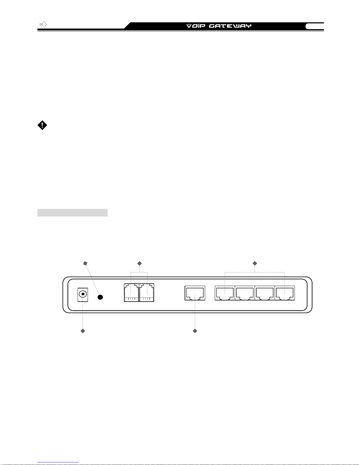
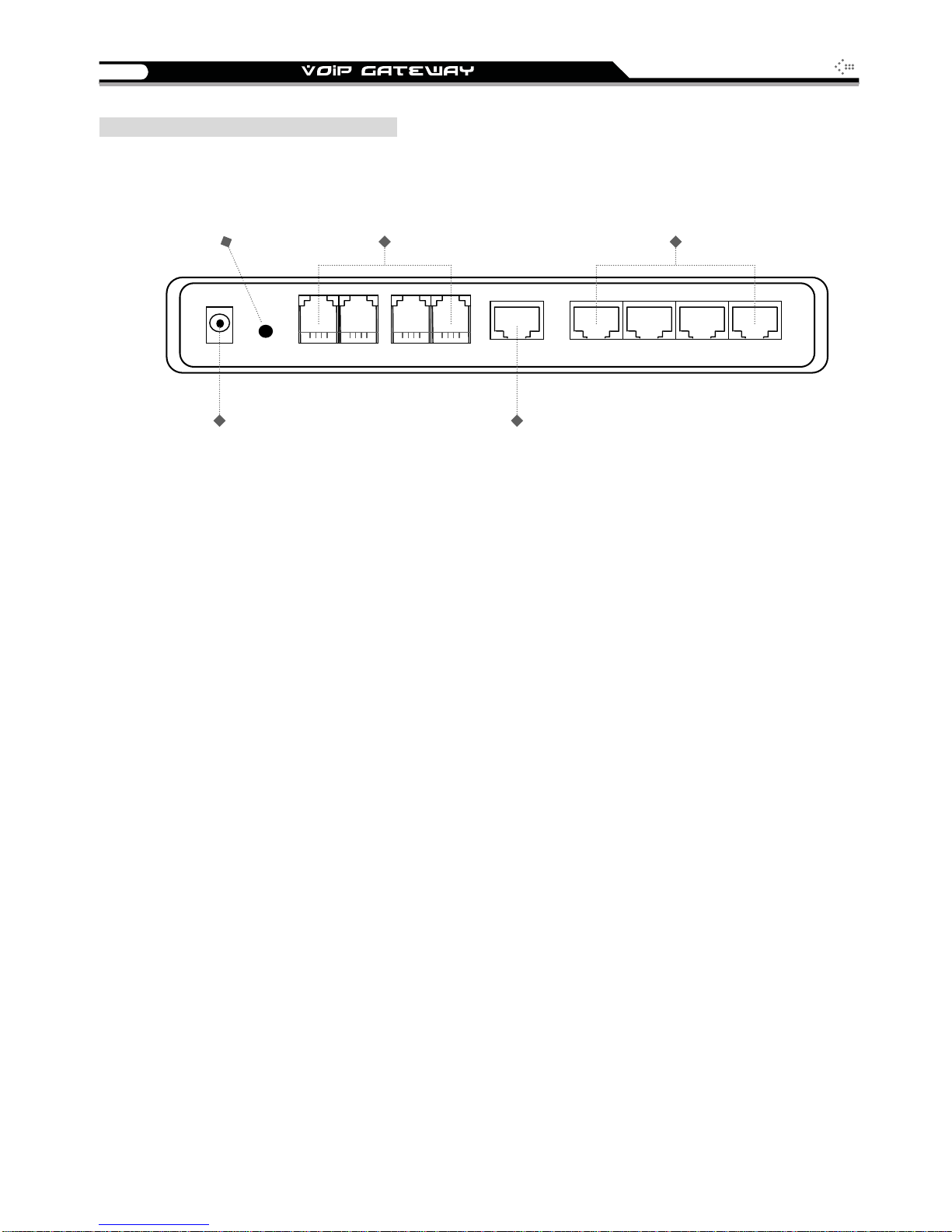
2S Model (2 FXS ports)
RESET
To reset the
gateway
Or to restore
factor
settings
FXS ports 1,2
(telephone connectors)
Phone sets connection
LAN ports 1 ~ 4
(built-in Ethernet switch)
Connect LAN hosts here
to share WAN connection.
IP sharing features enabled
DC+12V Reset P1 WAN L1
POWER
Connects to the power
adapter (comes with
the gateway)
P2 L2 L3 L4
WAN port
Connects to broadband
Networks such as AD SL,
Cable Modem or Router
4
y
y
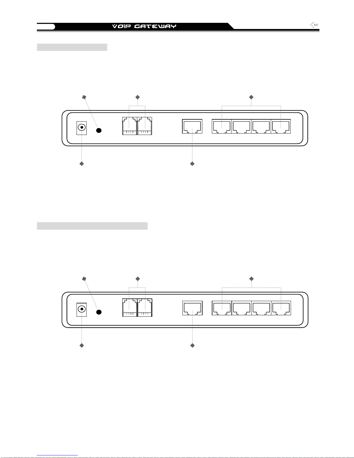
2O Model (2 FXO ports)
RESET
To reset the
gateway
Or to restore
settings
factor
FXO ports 1 ~ 2
(PSTN line connectors)
Connect to PSTN lines
SIP Operation Manual
LAN ports 1 ~ 4
(Built-in Ethernet switch)
Connect LAN hosts here
to share WAN connection.
IP sharing features enabled
DC+12V Reset WAN L1
P2 L2 L3 L4
POWER
Connects to the power
adapter (comes with
the gateway)
1S1O Model (1 FXO and 1 FXS ports)
RESET
To reset the
gateway
Or to restore
settings
factor
FXS port: 1
FXO port: 2
FXS connects to phone set;
FXO connect to PSTN line
WAN port
Connects to broadband
Networks such as AD SL,
Cable Modem or Router
LAN ports 1 ~ 4
(built-in Ethernet switch)
Connect LAN hosts here
to share WAN connection.
IP sharing features enabled
DC+12V Reset P1 WAN L1
POWER
Connect to the power
adapter (comes with
the gateway)
P2 L2 L3 L4
WAN port
Connects to broadband
Networks such as AD SL,
Cable Modem or Router

SIP Operation Manual
y
A
5
4 ports gateway model: 4S / 4O / 2S2O / 3S1O
Front Panel
VoIP Gatewa
WAN, LAN indicators Status indicators
Voice ports indicators
L1
WAN
P2P3P4L2L3L4 Power
P1
larm
RUN
Power Indicator: Green light indicates a normal power supply.
Run Indicator: Blinking green light indicates normal operation.
Alarm Indicator: When the system starts up, the red light will blink. It also indicates the
gateway’s abnormal operation.
Voice ports indicators: Indicate connection and activity on the port 1 – 4.
WAN stands for the WAN Port Indicator.
L1 – L4 stands for the LAN Port Indicator.
When starting up the system, the Alarm, Run, and Power indicators will light up. Af ter about 40
seconds, the Alarm indicator will go off, the Run indicator will blink green, and the Power
indicator will stay green (under normal operating conditions). If the Alarm indicator continues
to blink, then the system is attempting to connect with your ISP and has yet to obtain an IP
address.
Once the WAN is connected, the WAN indicator will light up green and, if data is being
transmitted over the Internet, the indicator blinks green and orange.
To restore factory default settings (IP address, User’s Name, Password):
(1) Disconnect the power plug.
(2) Press and hold the reset button.
(3) Reconnect the power plug while pressing down on the reset button.
(4) Release the reset button after 6 seconds. Factory settings will be restored.
6
y
SIP Operation Manual
Model Description
4S: P1-P4 stand for Phone1-Phone4. Connect to your analog telephone.
4O: P1-P4 stand for Line1-Line4. Connect to your original telephone line on the wall jack with
RJ-11 cable.
2S2O: P1-P2 stand for Phone1-Phone2 and P3-P4 stand for Line1-Line2. Phone ports are connected
to your analog telephone, and Line ports are connected to your original telephone line on the wall jack
with RJ-1 1 cable. Each FXS is relayed to each FX O symmetrically before the power is connected or in
the occasion of a power failure.
3S1O: P1-P3 stand for Phone1-Phone3 and P4 stand for Line1. Phone ports are connected to your
analog telephone, and Line port is connected to your original telephone line on the wall jack with RJ-11
cable. P1 will be relayed to P4 so that emergency calls can be made before the power is connected or
in the occasion of a power failure.
WARNING: DO NOT (1) connect the phone ports to eac h other (FXS to FXS) or (2) connect any
phone port directly to a PSTN line (FXS to PSTN) or to an internal PBX line (FXS to PBX
extension). Doing so may damage your VoIP gateway.
Rear Panel
4S Model (4 FXS ports)
RESET
To reset the
gateway or to
restore
settings
factor
DC+12V Reset P1 WAN L1
POWER
Connects to the power
adapter (comes with
the gateway)
FXS ports 1 ~ 4
(telephone connectors)
Connects to phone sets
P2 P3 P4 L2 L3 L4
LAN ports 1 ~ 4
(built-in Ethernet switch)
Connect LAN hosts here
to share WAN connection.
IP sharing features enabled
WAN port
Connects to broadband
Networks such as AD SL,
Cable Modem or Router
SIP Operation Manual
y
y
7
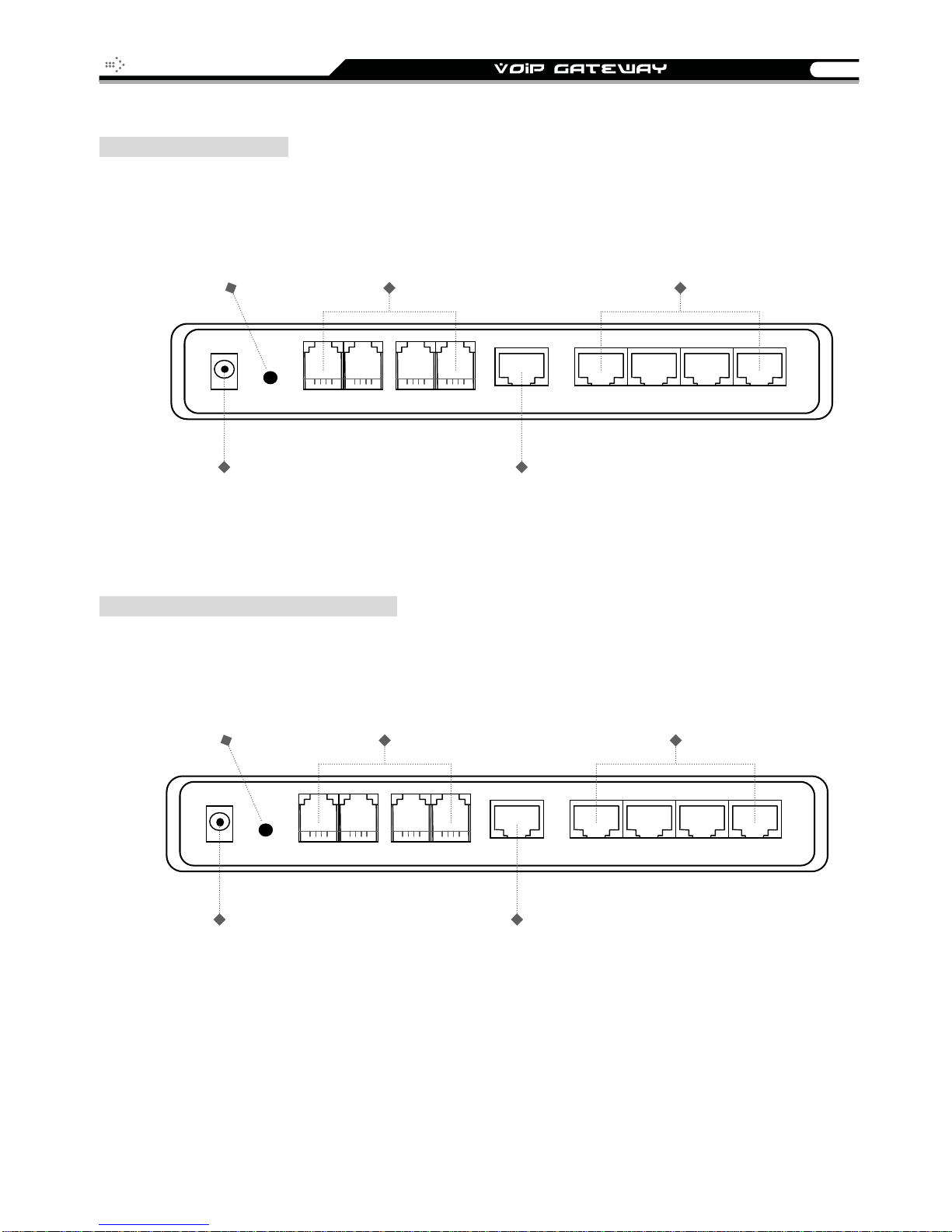
4O Model (4 FXO ports)
RESET
To reset the
gateway
or to restore
settings
factor
DC+12V Reset P1 WAN L1
FXO ports 1 ~ 4
(PSTN line connectors)
Connects to PSTN lines
P2 P3 P4 L2 L3 L4
POWER
Connects to the power
adapter (comes with
the gateway)
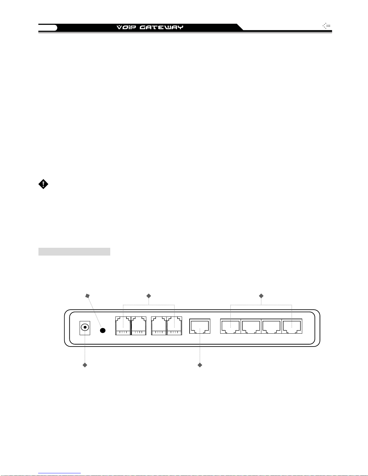
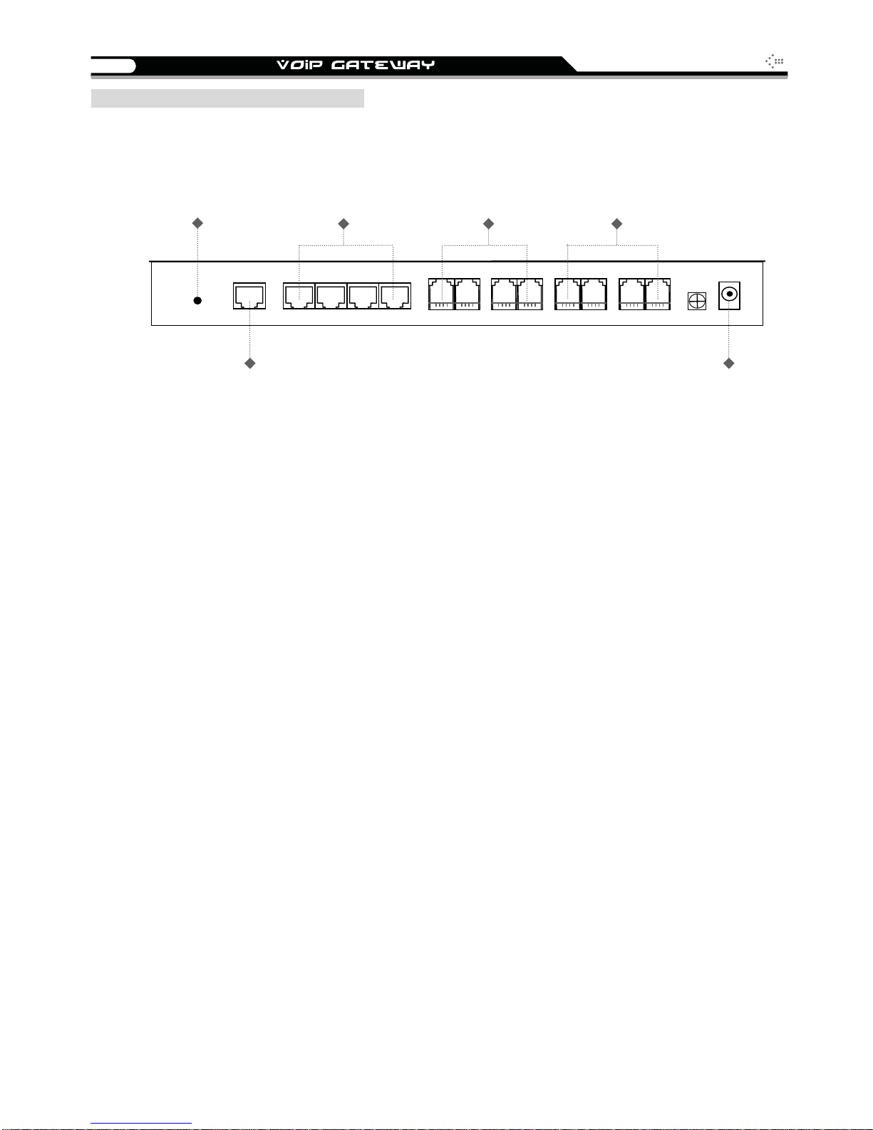
2S2O Model (2 FXS and 2 FXO ports)
RESET
To reset the
gateway
Or to restore
factor
settings
FXS ports 1,2
FXO ports 3,4
FXS to telephone set;
FXO to PSTN lines
LAN ports 1 ~ 4
(built-in Ethernet switch)
Connect LAN hosts here
to share WAN connection.
IP sharing features enabled
WAN port
Connects to broadband
Networks such as AD SL,
Cable Modem or Router
LAN ports 1 ~ 4
(built-in Ethernet switch)
Connect LAN hosts here
to share WAN connection.
IP sharing features enabled
DC+12V Reset P1 WAN L1
POWER
Connects to the power
adapter (comes with
the gateway)
P2 P3 P4 L2 L3 L4
WAN port
Connects to broadband
Networks such as AD SL,
Cable Modem or Router
8
y
3S1O Model (3 FXS and 1 FXO ports)
RESET
To reset the
gateway
Or to restore
factor
settings
FXS ports : 1, 2, 3
FXO ports : 4
FXS to telephone set;
FXO to PSTN lines
SIP Operation Manual
LAN ports 1 ~ 4
(built-in Ethernet switch)
Connect LAN hosts here
to share WAN connection.
IP sharing features enabled
DC+12V Reset P1 WAN L1
POWER
Connects to the power
adapter (comes with
the gateway)
P2 P3 P4 L2 L3 L4
WAN port
Connects to broadband
Networks such as AD SL,
Cable Modem or Router

SIP Operation Manual
A
y
9
8 ports gateways model: 8S / 8O / 6S2O / 4S4O
Front Panel
Voice ports indicators
P5
P6P7P8
P1P2P3P4
WAN, LAN indicators Status indicators
VoIP Gatewa
larm
L1
L2L3L4
WAN
RUN
Power Indicator: Green light indicates a normal power supply.
Run Indicator: Blinking green light indicates normal operation.
Alarm Indicator: When the system starts up, the red light will blink. It also indicates the
gateway’s abnormal operation.
Voice ports indicators: Indicate connection and activity on the port 1 – 8.
WAN stands for the WAN Port Indicator.
L1 – L4 stands for the LAN Port Indicator.
When starting up the system, the Alarm, Run, and Power indicators will light up. After about 40
seconds, the Alarm indicator will go off, the Run indicator will blink green, and the Power
indicator will stay green (under normal operating conditions). If the Alarm indicator continues
to blink, then the system is attempting to connect with your ISP and has yet to obtain an IP
address.
Once the WAN is connected, the WAN indicator will light up green and, if data is being
transmitted over the Internet, the indicator blinks green and orange.
To restore factory default settings (IP address, User’s Name, Password):
(1) Disconnect the power plug.
(2) Press and hold the reset button.
(3) Reconnect the power plug while pressing down on the reset button.
(4) Release the reset button after 6 seconds. Factory settings will be restored.
Power

10
SIP Operation Manual
Model Description
8S: P1-P8 stand for Phone1-Phone8. Connect to your analog telephone.
8O: P1-P8 stand for Line1-Line8. Connect to your original telephone line on the wall jack with
RJ-11 cable.
6S2O: P1-P6 stand for Phone1-Phone6 and P7-P8 stand for Line1-Line2. Phone ports are connected
to your analog telephone, and Line ports are connected to your original telephone line on the wall jack
with RJ-1 1 cable. P1 will be relayed to P7, and P2 is relayed to P8 to reach PSTN before the power is
connected or in the occasion of a power failure.
4S4O: P1-P4 stand for Phone1-Phone4 and P5-P8 stand for Line5-Line8. Phone ports are connected
to your analog telephone, and Line ports are connected to your original telephone line on the wall jack
with RJ-1 1 cable. Each FXS is relayed to each FX O symmetrically before the power is connected or in
the occasion of a power failure.
WARNING: DO NOT (1) connect the phone ports to eac h other (FXS to FXS) or (2) connect any
phone port directly to a PSTN line (FXS to PSTN) or to an internal PBX line (FXS to PBX
extension). Doing so may damage your VoIP gateway.
Rear Panel
8S Model (8 FXS ports)
RESET
To reset the
gateway
Or to restore
factory settings
RESET
WAN
WAN port
Connects to broadband
Networks such as ADSL,
Cable Modem or Router
LAN ports 1 ~ 4
(built-in Ethernet switch)
Connect LAN hosts here
to share WAN connection.
IP sharing features enabled
L1
L2 L3 L4
P1
P2 P3 P4
FXS ports 1 ~ 8
(telephone connectors)
Connects to phone sets
P5
P6
P7 P8
GND DC12V
POWER
Connects to the power
Adapter (comes with
the gateway)
SIP Operation Manual
11
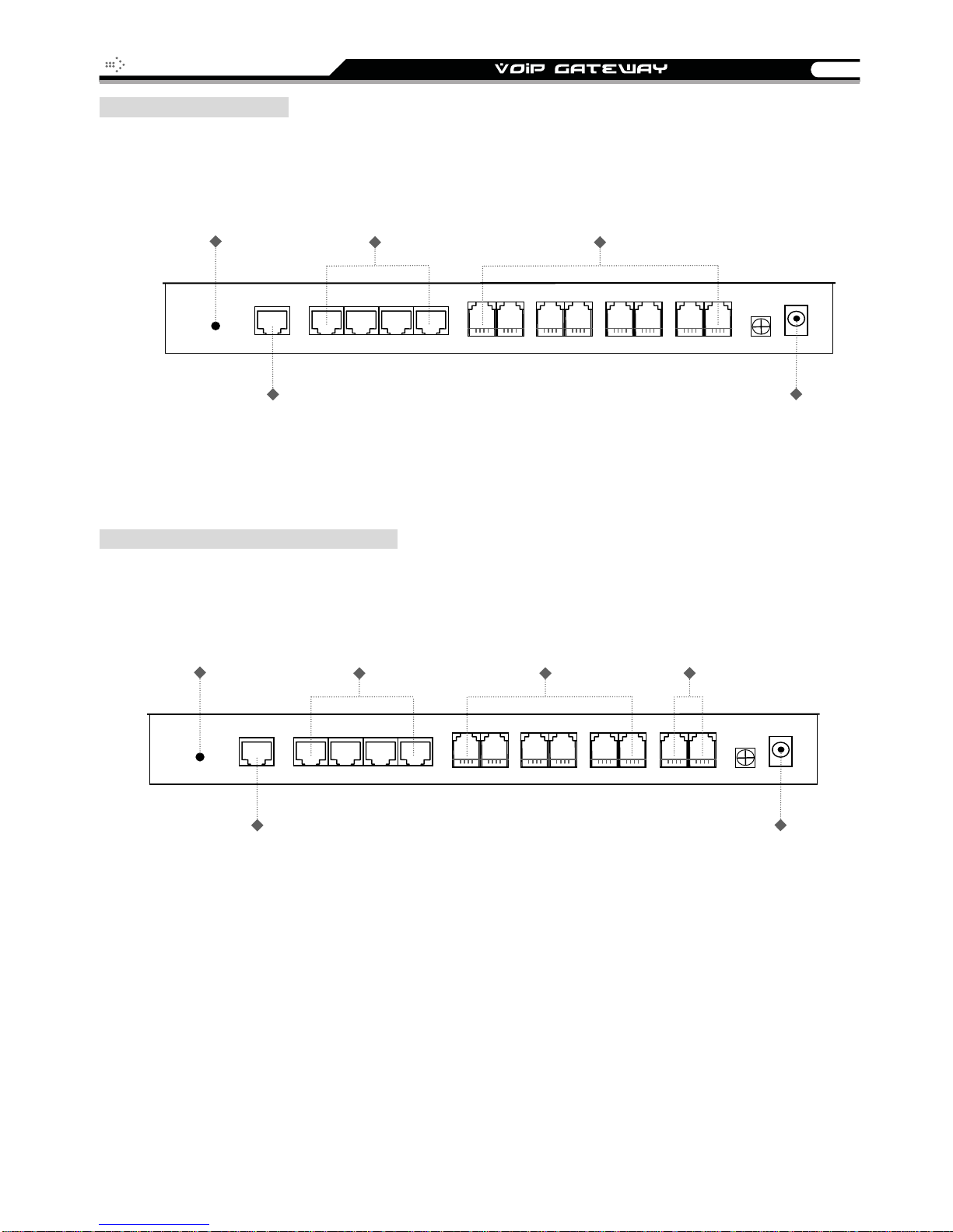
8O Model (8 FXO ports)
RESET
To reset the
gateway
or to restore
factory settings
RESET
WAN
LAN ports 1 ~ 4
(built-in Ethernet switch)
Connect LAN hosts here
to share WAN connection.
IP sharing features enabled
L2 L3 L4
L1
WAN port
Connects to broadband
Networks such as ADSL,
Cable Modem or Router
6S2O Model (6 FXS and 2 FXO ports)
RESET
To reset the
gateway
or to restore
factory settings
LAN ports 1 ~ 4
(built-in Ethernet switch)
Connect LAN hosts here
to share WAN connection.
IP sharing features enabled
FXO ports 1 ~ 8
(PSTN line connectors)
Connects to PSTN lines
P1
P2 P3 P4
FXS ports 1 ~ 6
(telephone connectors)
Connects to phone sets
P6
P7 P8
P5
FXO ports 7,8
(PSTN line connectors)
Connects to PSTN lines
GND DC12V
POWER
Connects to the power
adapter (comes with
the gateway)
RESET
WAN
L1
WAN port
Connecst to broadband
Networks such as ADSL,
Cable Modem or Router
L2 L3 L4
P1
P2 P3 P4
P5
P6
P7 P8
GND DC12V
POWER
Connects to the power
adapter (comes with
the gateway)
12
4S4O Model (4 FXS and 4 FXO ports)
RESET
To reset the
gateway
or to restore
factory settings
LAN ports 1 ~ 4
(built-in Ethernet switch)
Connect LAN hosts here
to share WAN connection.
IP sharing features enabled
FXS ports 1 ~ 4
(telephone connectors)
Connects to phone sets
SIP Operation Manual
FXO ports 5~8
(PSTN line connectors)
Connects to PSTN lines
RESET
WAN
WAN port
Connects to broadband
Networks such as ADSL,
Cable Modem or Router
L1
L2 L3 L4
P1
P2 P3 P4
P5
P6
P7 P8
GND DC12V
POWER
Connects to the power
adapter (comes with
the gateway)
SIP Operation Manual
13
2. Installation and Applications
Network Interface
The network interface is divided into 4 basic modes as described below:
Gateway can be assigned with a Public IP Address
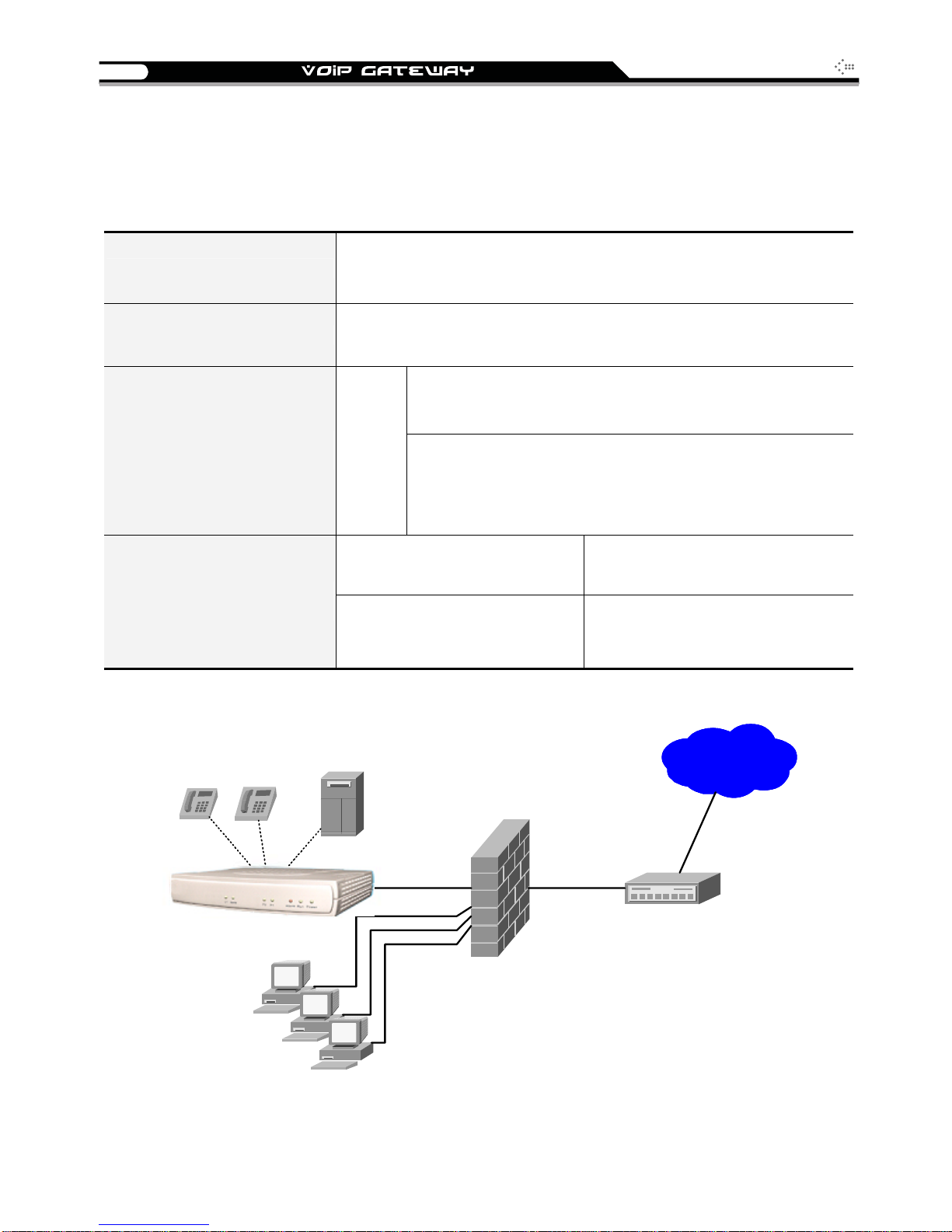
Gateway can be built under the existing NAT
Gateway can be assigned with a Public IP address and serves as an IP sharing router.
Gateway can be assigned with a Public IP address and serves as a bridge
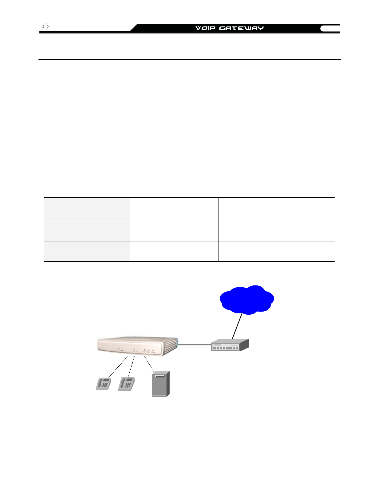
Gateway Assigned with a Public IP Address
The gateway will have a Public IP address for Internet connection regardless of whether it is a
static IP address, DHCP (using a Cable Modem), or PPPoE (Dialup / ADSL).
Gateway IP Settings
NAT/STUN Settings Unnecessary (Disabled)
DDNS Settings Unnecessary (Disabled)
Need to be set up as static
IP, DHCP, or PPPoE
WAN
Leased line / AD SL / C ab l e modem
InternetInternet
Phone
Phone
PBX
14
SIP Operation Manual
Gateway in a NAT network
The gateway uses a virtual IP address and the IP sharing function of other systems to connect
to the Internet.
Please avoid IP address 192.168.0.1-192.168.8.254 (You may need
LAN IP address of IP sharing
to change the settings of IP sharing or change SIP series Gateway
LAN Port IP address)
Gateway IP Settings
NAT /STUN Settings
DDNS Settings
Set as static IP address, and assign the LAN IP address of the IP
sharing to the Default Gateway.
If the WAN of the IP sharing device has static IP address,
then the NAT IP address is set as the Public IP address of
the IP sharing.
Enable
If the WAN of the IP sharing device uses a dynamic IP
address, then it has to comply with the DDNS settings.
When suing NAT, you must enter the URL (Uniform
Resource Locator) that is registered to the DDNS server.
The WAN of the IP sharing
device has a static IP address.
The WAN of the IP sharing
device has a dynamic IP
address.
Disabled
Enabled: enter the registered URL
(Uniform Resource Locator) into
NAT / DDNS→NAT Public IP
InternetInternet
Phone
Phone
PC
PC
PBX
PC
WAN
Leased l ine / ADSL / C able m odem
Firewall / NAT
SIP Operation Manual
15
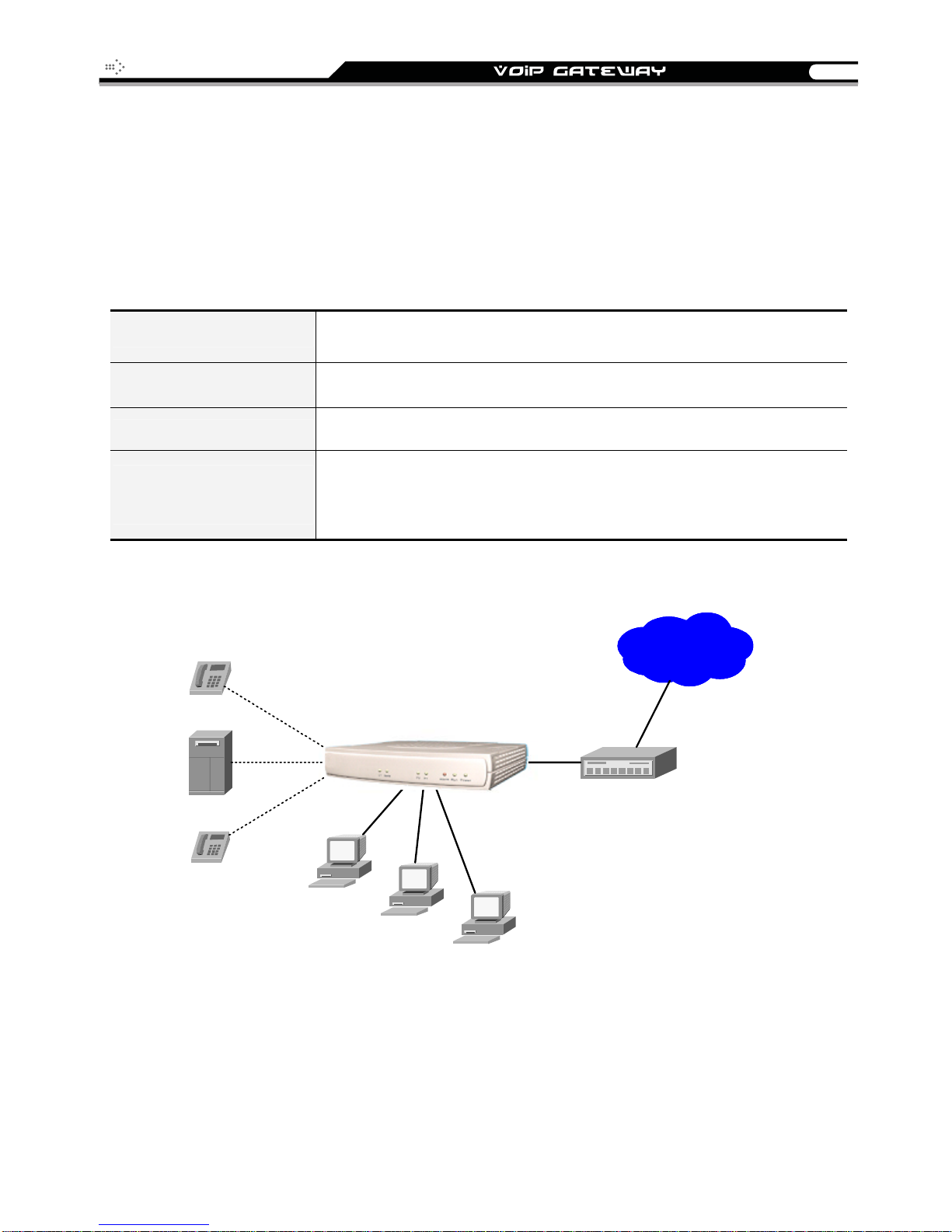
Gateway assigned with a Public IP Address and serving as an IP
sharing device
The gateway will have a Public IP address regardless of whether it is a static IP application,
DHCP (using a Cable Modem), or PPPoE (To connect to your ADSL account), which can then
use the functions of built-in IP sharing function to allow other PCs to be on-line at the same time.
Gateway IP Settings Need to be set up as static IP, DHCP, or PPPoE
NAT/STUN Settings Unnecessary (Disabled)
DDNS Settings Unnecessary (Disabled)
For settings at PC end,
please refer to
IP sharing functions
Phone
PBX
Phone
VoIP gateway serving as an IP sharing device
PC uses a static IP address ranging from: 192.168.8.1-192.168.8.253
Subnet Mask:255.255.255.0
Default Gateway:192.168.8.254
InternetInternet
WAN
WAN
LAN
PC
Leased lin e / ADSL / Cable mod em
PC
PC
16
SIP Operation Manual
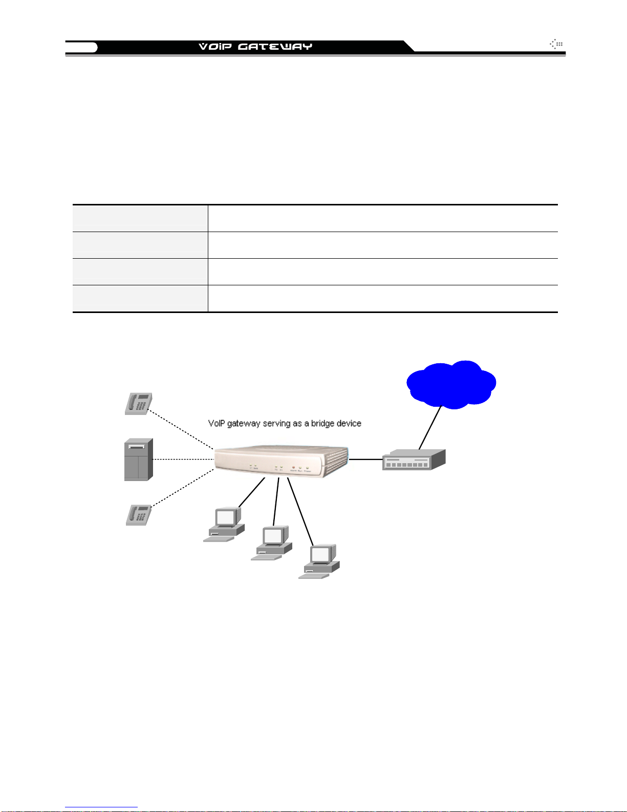
Gateway assigned with a Public IP Address and serving as a
bridge
The gateway will have a Public IP address regardless of whether it is a static IP application,
DHCP (using a Cable Modem), or PPPoE (To connect to your ADSL account), which can then
use the functions of built-in Bridge function to allow a PC to be on-line at the same time.
Gateway IP Settings Need to be set up as static IP, DHCP, or PPPoE
NAT/STUN Settings Unnecessary (Disabled)
DDNS Settings Unnecessary (Disabled)
For settings at PC end PC uses the original IP address
Phone
PBX
Phone
VoIP gateway serving as an IP sharing device
WAN
WAN
LAN
Leased lin e / ADSL / Cable mod em
PC
PC
PC
InternetInternet
SIP Operation Manual
17
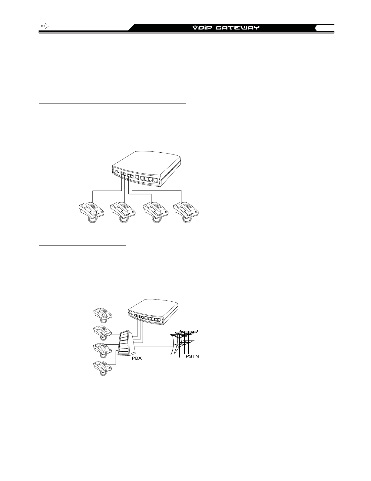
Telephone Interface Description
Example for 4S gateway:
4S gateway connecting directly to phone sets
After connecting telephone sets to P1-P4, users can make direct calls, (P1-P4 are FXS interfaces).
Each set acts as an independent extension line.
Integrating the 4S with PBX
P1-P4 is FXS interfaces, and some of them can be connected to telephone sets for direct calls.
Others can be connected to the PBX so other extension lines can make VoIP calls.

18
SIP Operation Manual
Example for 4O gateway:
4O model connecting directly to the Telephone Line of a PSTN
P1-P4 is FXO interfaces and can all be connected to a PSTN to serve as a bridge between the
PSTN and other VoIP telephones. The system also allows a call to be made from a traditional
telephone line to connect with a user behind the gateway.
Integrating the 4O with PBX
P1-P4 is FXO interfaces and can be connected with PBX extension lines (exclusively for analog
interface, not applicable for digital type).
SIP Operation Manual
19
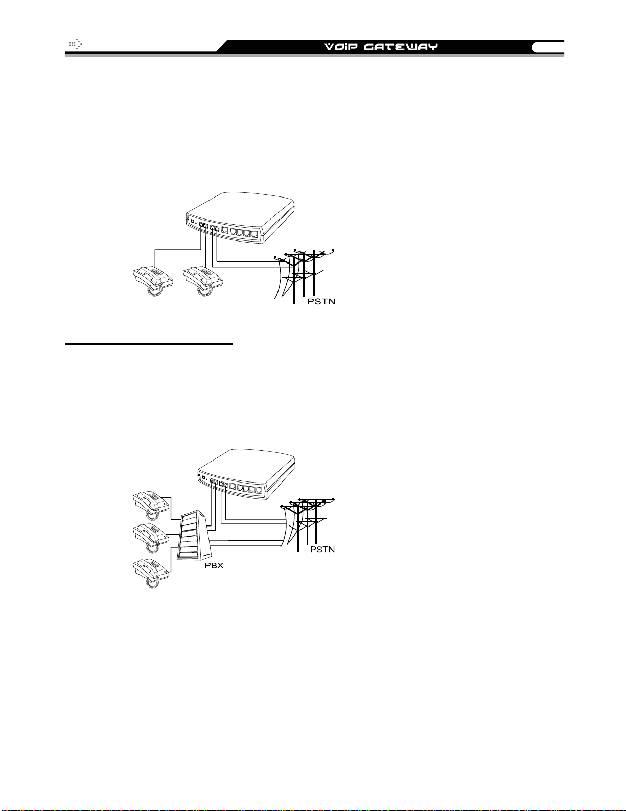
Example for 2S2O gateway:
P1-P2 is FXS interfaces and can be directly connected to a telephone set for direct calls. P3-P4 is
FXO interfaces and can be connected to a PSTN to serve as a bridge between the PSTN and
other VoIP telephones. The system also allows a call to be made from a traditional telephone line
to connect with a gateway user.
Integrating the 2S2O with PBX
P1-P2 is FXS interfaces and can be connected to a PBX CO or an analog telephone; P3-P4 is
FXO interfaces and can be connected to a PSTN to act as a bridge between the PSTN and other
VoIP telephones. The system also allows a call to be made from a traditional telephone line to
connect with a gateway user.

20
SIP Operation Manual
3. Setting the Gateway through IVR
VoIP transmits voice data (packets) via the Internet. One effect of this is that telecommunications
quality is closely related to the condition and status of the network environment. If any of the parties
involved in VoIP communications has insufficient bandwidth or frequent packet loss, the
telecommunication quality will be poor. Therefore, excellent telecommunication can only happen
when the gateway is connected to the Internet and when the network environment is stable.
Preparation
Install the gateway according to instructions. Connect the power supply, telephone set,
telephone cable, and network cable properly as described in Installation and
Applications.
If a static IP is used, confirm the correct IP settings of the WAN Port (IP address, subnet
mask, and default gateway). Please contact your local Internet Service Provider (ISP) if
you have any questions.
If using dialup ADSL (PPPoE) for network connection, confirm the dialup account number
and password.
If you intend to operate the gateway under a NAT, the gateway WAN port IP address and
LAN port should not use the same range in order to avoid phone failures.
The gateway provides two setting modes:
1. Telephone IVR Configuration Mode
2. Browser Configuration Mode
The IVR provides basic query and setting functions, while the browser provides a full setting
function.
IVR (Interactive Voice Response)
The gateway provides convenient IVR functions. Users only need to pick up a handset and enter
the function code for the query and setting without using a PC.
NOTE: After finishing the setup, make sure the new settings are saved. This will enable the new
settings to take effect after the gateway is restarted.

SIP Operation Manual
21
Instructions
FXS Port: Connect FXS port to a telephone. To access IVR mode, you should enter factory
default code “** #” . If it requires password, enter ** password #”. Character to number
conversion information is provide in the PPPoE Character Conversion Table. After
entering the correct IVR password, you will hear an indication tone after which the gateway
is in IVR setup mode. Enter function codes to check or set the gateway configuration.
(Please refer to IVR Function Table for function codes).
Example: If your password is “1234”, enter **1234#
Next enter a function code to check or configure the gateway. If your password is “admin”,
enter ***4144534954#
FXO Port: Use extension line to dial the phone number of FXO port. You will hear the
instruction “enter value”, enter factory default code ** #
password, enter ** password #
PPPoE Character Conversion Table. After entering the correct IVR password, you will
hear an indication tone after which the gateway is in IVR setup mode. Enter function codes
to check or set the gateway configuration.
Once the first setting or query has been completed, you will hear a dial tone. Use the same
procedure to make a second query or setting. To exit IVR mode, simply hang up the phone.
Example: enter **#
address) the gateway responds with an IP address you can continue with more
settings or queries: enter 111
address).
.
. Character to number conversion information is provide in the
(You are now in IVR mode) enter 101 (to query about the current IP
(to set a new IP address) enter 192*168*1*2 (new IP
so that you are now in IVR setup mode.
to access IVR mode. If it requires
Save Settings
After completing all of your settings, dial 509 (Save Settings). Wait for about 3 seconds, you should
hear a confirmation tone “1.” You can now hang up the phone. Please reboot the gateway to
enable new settings.
To inquire about the current gateway’s WAN Port IP address
After completing all of your settings, dial 101. The gateway will repeat the current WAN Port IP
address. If the gateway does not repeat the IP address, this indicates that the gateway is not
currently connected to the Internet. Please check to be certain that the cable connection, account
number, and password are all correct.
Software Upgrade
IVR provides online upgrades. Once in IVR mode, enter “209” and you will hear “Enter Value“.
Enter your IP address followed by “#” (i.e.: 61*30*25*89#
Enter the Listen Port Number followed by “#” (i.e.: 69#
NOTE: Please contact your servi ce provider for software upgrade.
). You will hear a second “Enter Value“.
).

22
A
IVR Functions Table:
SIP Operation Manual
Function
Code
111/101 WAN Port IP address Set/Query
112/102 WAN Port Subnet Mask Set/Query
113/103 WAN Port Default Gateway Set/Query
114/104
118 Restart
311/301 LAN Port IP address Set/Query
312/302 LAN Port Subnet Mask Set/Query
131/132 Play/Record greeting message
133 Saving greeting message
217/207
109 Restoring factory default IP address configuration
Description Example / Notes
Current Network IP Access Set/Query (1: Static IP,
2.DHCP, 3.PPPoE)
Set/Query the gateway web configuration interface
port number
Use function code 114 to select
1 for Static IP connection then
setup the IP address
static IP address for WAN Port
IP:192.168.1.2
Subnet Mask:255.255.255.0
Default Gateway:192.168.1.254
409 Restoring factory default settings
509 Save settings
Setting IVR and the language used on the Web GUI
900
209 Software Upgrade
(1: English, 2: Traditional Chinese, 3: Simplified
Chinese)

SIP Operation Manual
23
IP Configuration Settings of WAN Port
Static IP Settings
NOTE: Complete static IP settings should include a static IP (option 1 under 114), IP address (111),
Subnet Mask (112
if you have any questions.
Function Command
), and Default Gateway (113). Please contact your local Internet Service Provider (ISP)
Select a Static IP
IP address Settings
Subnet Mask Settings
Default Gateway
Settings
Save Settings and
Restart
After entering IVR mode, dial 114.
After hearing “Enter value”, dial 1 (to select static IP)
After entering IVR mode, dial 111. After hearing “Enter value”, enter your
IP address, followed by “#”.
Example: If the IP address is 192.168.1.200, dial 192*168*1*200#.
After entering IVR mode, dial 112. After hearing “Enter value”, enter your
subnet mask, followed by “#”.
Example: If the mask value is 255.255.255.0, dial 255*255*255*0#.
After entering IVR mode, dial 113. After hearing “Enter value”, enter your
default gateway’s IP address, followed by “#”.
Example: If the default gateway is 192.168.1.254, dial 192*168*1*254#.
To save settings, dial 509
current settings. After hearing “one”, dial 118
for about 40 seconds for the gateway to restart, and then enter 101
check whether or not the IP address is retained. If the IP address is not
repeated, this indicates that the gateway is not properly connected.
Please check to be certain that the cable connection, account, and
password are all correct.
(Save Settings). The gateway will save the
to restart the gateway. Wait
to
Dynamic IP (DHCP) Settings
After entering IVR mode, dial 114.
You will hear “Enter value”, Dial 2 to select DHCP.
Dial 509 to save settings.
Dial 118 to reboot the gateway.
Wait for about 40 seconds for restart, and then enter 101
address is retained.
to check whether or not the IP

24
SIP Operation Manual
ADSL PPPoE Settings
NOTE: Before setting PPPoE, you must have PPPoE account (121) and PPPoE pass word (122) provided
by your local Internet Service Provider (ISP).
Select a PPPoE
After entering IVR mode, dial 114
.
You will hear “Enter value”.
Dial 3 to select PPPoE.
Set PPPoE account
After entering IVR mode, dial 121
.
You will hear “Enter value”.
Enter account number and # (speed up dialing).
Example: If the account is “84943122 @ hinet.net”, please enter 08 0 4 0 9 0 4 0 3 0 1 0 2 0 2 7 1 4 8 4 9 5 4 4 5
60 72 54 45 60 #.
NOTE: It is necessary to enter two digits for each character/number; for example, enter “01” for “1 ” and
“11” for “A”.
PPPoE Password Setting
After entering IVR mode, dial 122
.
You will hear “Enter value”.
Enter password number and # (speed up dialing).
Example: If the password is “3ttixike”, please enter “03 60 60 49 64 49 51 45#”.
Save Settings and Restart
Dial 509
Dial 118
Wait for about 40 seconds for restart, and then enter 101
to save settings.
to reboot the gateway.
to check whether or not the IP
address is retained. If the IP address is not repeated, this indicates that the gateway is not
been properly connected. Please check to be certain that the cable connection, account, or
password are all correct.
Record Greeting File
The gateway allows users to record their incoming call greeting messages when FXO
receives an incoming call.
After entering IVR mode, dial 132
call greeting message. Simply hang up the phone to end recording.
After recording, to listen to the recorded message, press 131. Press 133 to save the
message.
. After hearing “Enter value”, start to record the incoming

SIP Operation Manual
25
PPPoE Character Conversion Table
The table below provides a list of PPPoE conversion codes. The first column in each pair of
columns lists the number, letter or symbol that you want to enter. The second column in each pair
(“Input Key”) tells you what code to enter for the corresponding number, letter or symbol.
Number Input Key
0 00 A 11 a 41 @ 71
1 01 B 12 b 42
2 02 C 13 c 43 ! 73
3 03 D 14 d 44 " 74
4 04 E 15 e 45 $ 75
5 05 F 16 f 46 % 76
6 06 G 17 g 47 & 77
7 07 H 18 h 48 ' 78
8 08 I 19 i 49 ( 79
9 09 J 20 j 50 ) 80
K 21 k 51 + 81
L 22 l 52 , 82
M 23 m 53 - 83
N 24 n 54 / 84
O 25 o 55 : 85
Upper Case
Letter
Input Key
Lower Case
Letter
Input Key Symbol Input Key
•
72
P 26 p 56 ; 86
Q 27 q 57 < 87
R 28 r 58 = 88
S 29 s 59 > 89
T 30 t 60 ? 90
U 31 u 61 [ 91
V 32 v 62 \ 92
W 33 w 63 ] 93
X 34 x 64 ^ 94
Y 35 y 65 _ 95
Z 36 z 66 { 96
| 97
} 98

26
SIP Operation Manual
4. Setting a Gateway with WEB Browser
The VoIP gateway allows users to configure its settings using a web interface (Web UI). You can
access the Configuration Menu by opening a web-browser (e.g., Internet Explorer or Netscape
Navigator) and entering the factory default LAN IP address: 192.168.8.254. The IP address of the
Web UI is same as the default LAN IP noted elsewhere in this user’s manual.
You can also use an ordinary telephone, connect it to the gateway, and dial ”101” to inquire about
the current WAN Port IP address and then use the WAN port to log-in.
Instructions
Open a Web-Browser (e.g., Explorer, Navigator, Opera, Firefox).
Enter the LAN port IP address. The default LAN port IP address is: 192.168.8.254.
The log-in screen below will appear after you connect. The factory default settings for Login
ID and Password are left blank (i.e., no login ID, no password).
Change the default settings of Administrator’s Name, Password and Web UI Login ID,
Password in Advanced Options.
The gateway does not allow multiple people to configure the gateway simultaneously. Please
remember to logout or restart the system if you are not using the web configuration function.
 Loading...