

X-Paq ASG-CT2500 User Manual

ASG-CT2500
ASG-SD2500 Series Screwdriver Controller
ŀ
User’s Guide
Version 2.0.0
June, 2012
Page 1

ASG Precision Fastening ASG-CT2500 User’s Guide
Version 2.0.0
Major Revision: June, 2012
Firmware Revisions
GUI: Firmware Version 2.1.1.0
Controller: Firmware Version C-6.11.0
To download the latest version of this manual visit:
www.asgprecisionfastening.com
ASG Precision Fastening
(888) 486-6163
15700 S. Waterloo Rd.
Cleveland, OH 44110
USA
© 2012 Jergens Inc.
All Rights Reserved
Page 2

Table of Contents
Safety Precautions…………………………………………………………………………..………………………………………………….5
Introduction……………………………………………………………………………………………..…………………………………………6
Installation………………………………………………………………………………………………………….…..………………….……..7
Run Tool Screen………………………………………………………………………………………………………………………………….9
Tool Information Screen
Setup Screen……………………………………………………………………………………………………………………………….…….12
Tool Triggering
Bolt Counts
Bolt Retries
Reverse Settings
Parameter Setup
Prevailing Torque
Bolt Sequences
Task Menu……………………………………………………………………………………………………………….……………...…….18
Renaming and Importing Tasks
Exporting Tasks
Input Programming…………………………………………………………………………………………………….……………...…….20
Task Select.
Enable Bolts.
Remote Start.
Reverse Select.
Remote Reset.
Remote Halt.
Output Programming………………………………………………………………………………………………..……………..……….25
Page 3

Input/Output Port Pin Guide………………………………………………………………….…………………………………………27
Graph Screens…………………………………………………………………………………..………………………………………………29
Graph Data Export
Data Screen……………………………………………………………………………………………………………………………………32
Erasing Data
Downloading Data
System Setup Screen…………………………………………………………………………………………………………..…………35
Passwords
Date/Time Settings
Tool Trigger Sensitivity
Tool Calibration
Controller Information
Firmware Updates
Touch Screen Calibration
LCD Brightness Adjustment
Service & Warranty………………………………………………………………………………………….…………………………….40
Page 4
Safety Precautions
Be sure to read all instructions and precautions contained in this manual, failu
result in personal injury and/or damage to tooling and components.
Do not operate or plug in the controller/system with wet hands or in wet environments.
Failure to observe this may result in injury due to electric shock.
roller is properly plugged in to a grounded electrical receptacle. Do not remove
the ground pin or use any adapter plugs.
Always shut down the controller when changing cables or tools. Failure to do so could damage
ork area clear of clutter and distractions that may cause the operator to lose control of
Tool cable must be properly routed and festooned to avoid tangling and trip hazards.
Always use safety glasses when using electrical
Do not use any part of the system (tool, cable, or controller) for anything other than its
specified application. Use of the system or its components for unintended applications could result in
injury to the operator, failure of the sy
Never modify or disassemble any component of the system. Modification or disassembly of the
system could result in injury and void the warranty.
Ensure the cont
the tool or controller.
re to do so may
Keep w
the tool or the components.
assembly tools.
stem, and could void the warranty.
Page 5
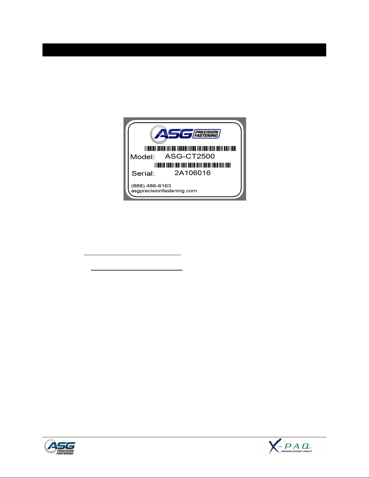
Introduction
Thank you for investing in a ASG-CT2500 Controller from ASG Precision Fastening! This user’s guide will
assist you with setting up your controller.
Please start by finding the serial number label on the bottom of the controller.
Take note of the serial number and record it below with your date of purchase. This information will be
necessary should any service be required in the future.
Serial Number: :
Date of Purchase: :
Page 6
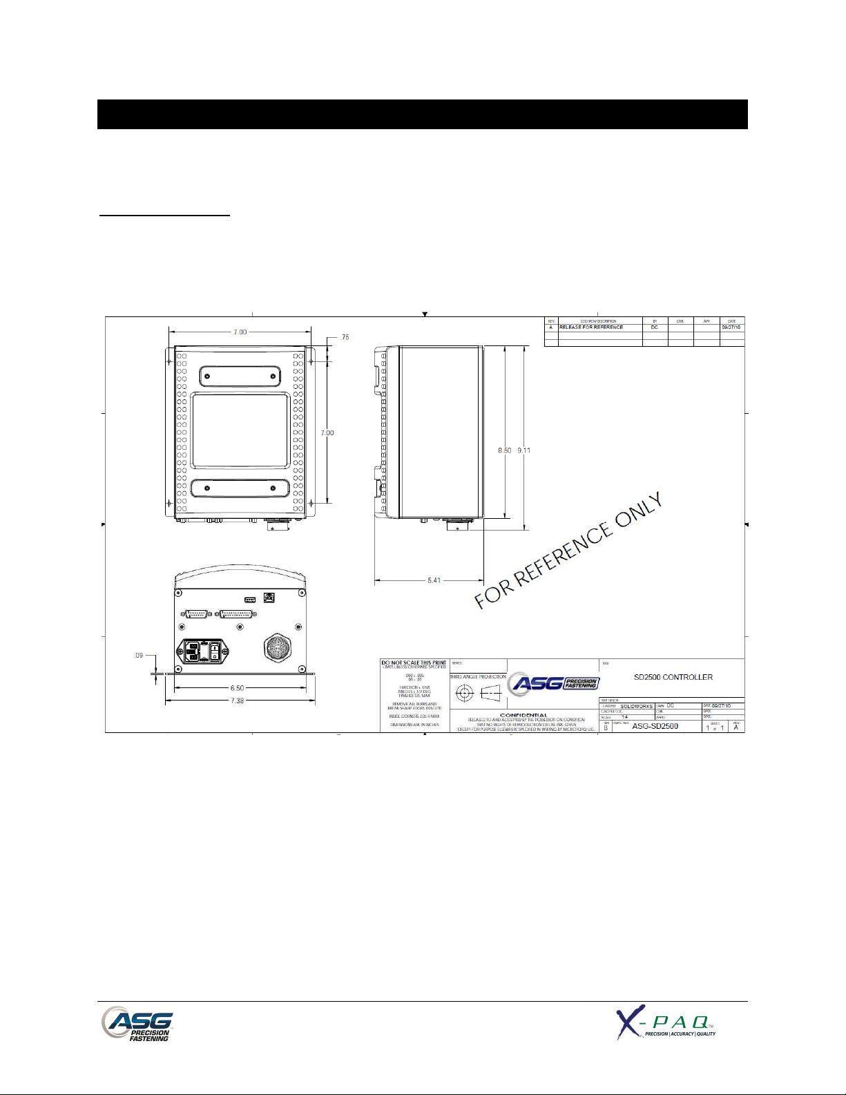
Installation
Installation of the ASG-CT2500 is very straightforward. Follow these steps to connect your system for
the first time:
Controller Mounting:
The ASG-CT2500 comes standard with a mounting plate for attaching to the wall, workbench, or tool
stand. Secure the controller using the (4) provided holes in the mounting plate. These provided holes
are meant for #6 screws, but can be enlarged to suit user’s needs.
Ensure the controller power cord can reach a properly grounded receptacle without creating a trip
hazard in the work area. The controller should also be mounted within view of the operator, and should
be accessible and within reach for programming and modification.
Page 7
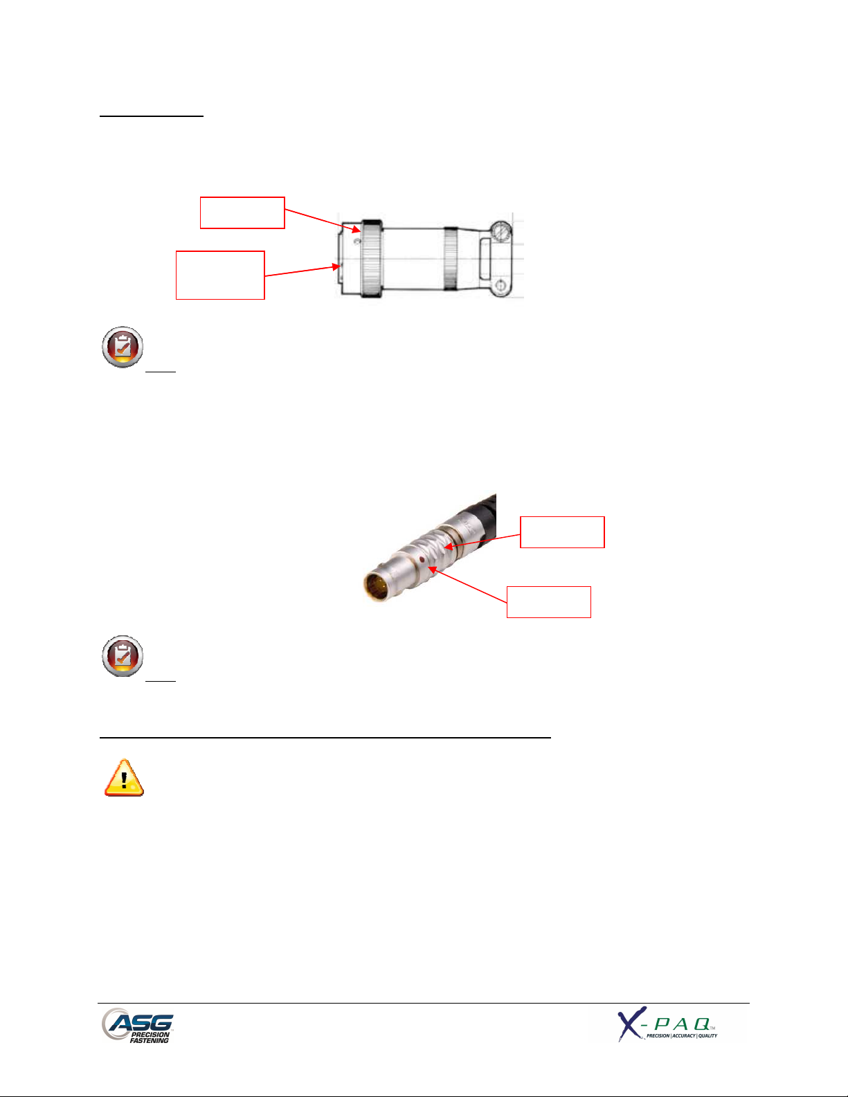
Tool Installation:
Connect the tool cable to the connector on the bottom of the controller by
tabs in the large cable connector. Align these tabs and insert the cable to the cont
lock on the cable connector clockwise until it
: To remove the cable from the controller, rotate the twist
clockwise until it pops free, and then remove the cable
SD2500 tool and identify the slot on the screwdriver connector into which the
screwdriver cable plugs. Find the red dot on the small end of the cable, and align it to the slot in the
cable to the tool firmly until it
: To remove the cable from the tool, slide the grip of the cable connector away from the
tool, then pull the cable out of the tool.
Connect the controller to the power source and power
Do not depress either the push to start spindle or the throttle lever during controller power
doing so will result in a ToolEE Error which will require a reboot of the controller.
Twist
-
lock
Alignment
Tabs
roller, then rotate the
lock on the cable connector
Grip
Dot
twist-
Note
counter-
Obtain the ASG-
screwdriver connector. Insert the
clicks into place.
from the controller.
clicks into place.
identifying
the alignment
-
Note
-up the controller.
-up,
Page 8

Run Tool Screen
1
2
3
4
5
13
7
8 9 10 11 12
6
1. Task Selection: Shows the user the current task, and allows the user to select one of 12
available tasks. Selecting the button with the task name will bring up
the Task Menu where another task may be selected or altered. The
arrow keys will advance to the previous or next task. Settings for bolt
counts, parameters, inputs, outputs, etc will switch with these actions
to the settings of the selected task.
2. Tool Information Button: Displays the Tool Information screen that shows tool characteristics.
3. Final Target: Displays the target value of the active Parameter, either torque or
angle.
4. Torque Reading: Displays the torque seen by the tool during or at the end of the
fastening cycle. This field will color code at the end of a fastening cycle
to denote Pass (green), Fail – High (red), or Fail – Low (yellow) as
defined by high and low limits of the selected Parameter.
5. Angle Reading: Displays the angle seen by the tool during or at the end of the fastening
cycle. This field will color code at the end of a fastening cycle to denote
Pass (green), Fail – High (red), or Fail – Low (yellow) as defined by high
and low limits of the selected Parameter. The field remains unhighlighted when Angle Monitoring is disabled within the Parameter.
6. Inputs: Displays (1) radio button for each of the (8) available inputs. The
appropriate radio button will illuminate blue when the input is active.
Page 9

7. Bolt Sequence Steps: Displays the sequence step and selected parameter. The parameter
name will be highlighted red, yellow, or green at the end of its cycle to
show its status.
8. Setup Button: Takes you to screens where you may set up Tasks, Parameters, Bolt
Sequences, Inputs, Outputs, and System Settings.
9. Graph Button: Displays the most recent fastening cycle graphically as Torque vs. Time,
Angle vs. Time, Torque vs. Angle, Speed vs. Time, and Power vs. Time.
10. Data Button: Displays a table that contains rundown characteristics for the last 100
fastening cycles. Additional data is available in the internal memory and
can be downloaded to a USB flash drive from this screen as well.
11. Repeat Button: Depressing this button keeps the controller on the current bolt in a
batch. The bolt sequence will not advance to the next bolt until the
button is released.
12. Reset Button: Depressing this button resets the fastening bolt count in the event of a
failure, retry lockout, user request. The reset button also resets any
outputs. This button can be disabled when the controller is locked with
a password.
13. Outputs: Displays (1) radio button for each of the (8) available outputs. The
appropriate radio button will illuminate blue when the output is active.
Page 10
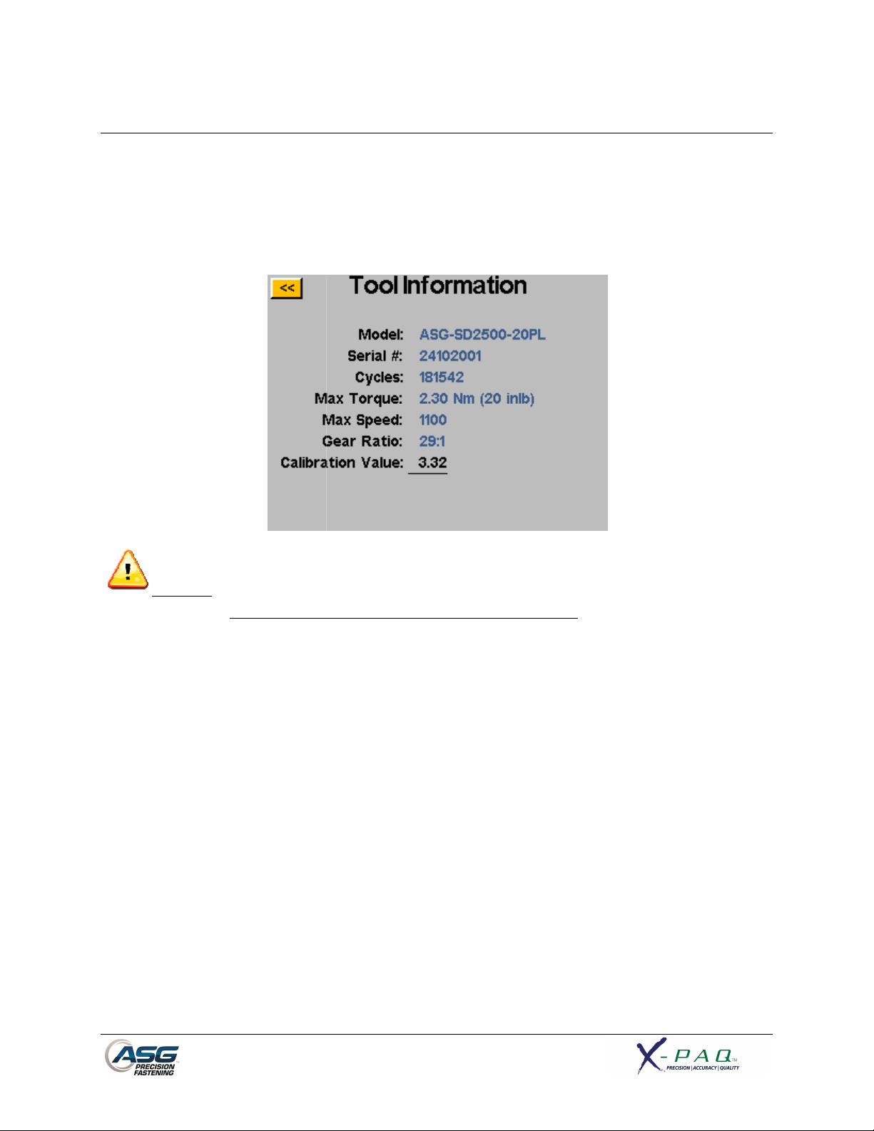
Tool Information Screen
This screen displays characteristics of the tool that is atta
Number of Cycles on the Tool
: Tapping on the Calibration Value will take you to a screen where the value can be
This screen is for qualified calibration technicians only.
lead to inaccurate torque readings and potential tool damage.
CT2500 controller such as:
Improperly changing the
• Model Number
• Serial Number
•
• Max Torque
ched to the ASG-
• Max Speed
• Gear Ratio
• Calibration Value
CAUTION
manually changed.
calibration value of the tool could
Page 11
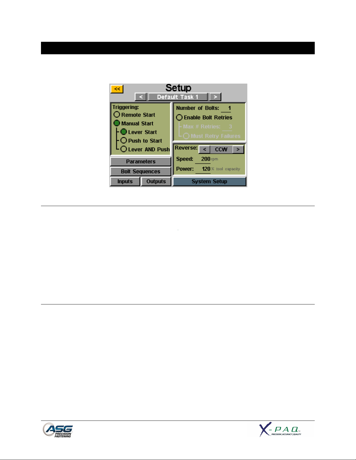
Setup Screen
Entering the setup screen allows you to modify the settings of each task’s parameters, bolt counts, bolt
sequences, inputs, outputs, reverse settings, and triggering.
Tool Triggering:
On the ‘Setup’ screen, each task can be set up to trigger the tool in the way that best fits that task. The
tool can be set up for remote start, lever start (if tool is equipped with a lever), push to start, lever or
push to start (together), or lever and push to start. To select, just tap the radio button next to the
desired option(s).
For remote start applications, the triggering will have to be configured in the ‘Inputs’ section of the Task
Setup screen. See the Input programming section of this manual for more details.
Bolt Counts:
Setting up the bolt counts for each task can be done through the task setup screen. Under the ‘Number
of Bolts:’ window, tap the underlined number to change the number of bolts to be secured on that task.
This will build what some users call a batch. The controller will display the bolt count on the ‘Run Tool’
screen.
The controller will accept up to 999 bolts per task, but once the bolt count rises above 50, individual
bolts cannot be programmed to different parameters in the ‘Bolt Sequences’ screen.
No matter how many bolts are in the batch, a torque or angle control parameter must be assigned to
a given bolt in order for it to run. See the Parameter Setup and Bolt Sequences sections of this
manual for more information.
Page 12
 Loading...