

XOXBOX XOXIO I/O Install Manual

I/O Install Manual ver 1.06
PCB Assembly and install documents created by BOOSTER
All original source documents and material created by BCBOX
Designed by BCBOX (Brian Castro)
The x0xi0 I/O & Overdrive kit is a rear panel mod for the x0xb0x. The kit requires good soldering skills and a general knowledge of electronics to be able to relate the
schematic to the board layout if troubleshooting is necessary. If you built your x0xb0x you can certainly install the kit. The most difficult part for most people will be removing
existing resistors & capacitors if you are installing the kit to a x0xb0x that is already assembled. There are up to (11) components that are removed and replaced with new
components or used as patch points for the mod. If you have very basic soldering skills and not much experience with a desoldering tool or soldering braid you may find it
difficult to remove solder from the pads after you have removed the components. There are step by step instructions for installing the kit so you will not need to refer to the
schematic. The schematic is only needed after completion if you are troubleshooting a section that is not working. Since the majority of the mods are independent of each
other it is very easy to troubleshoot a problem.
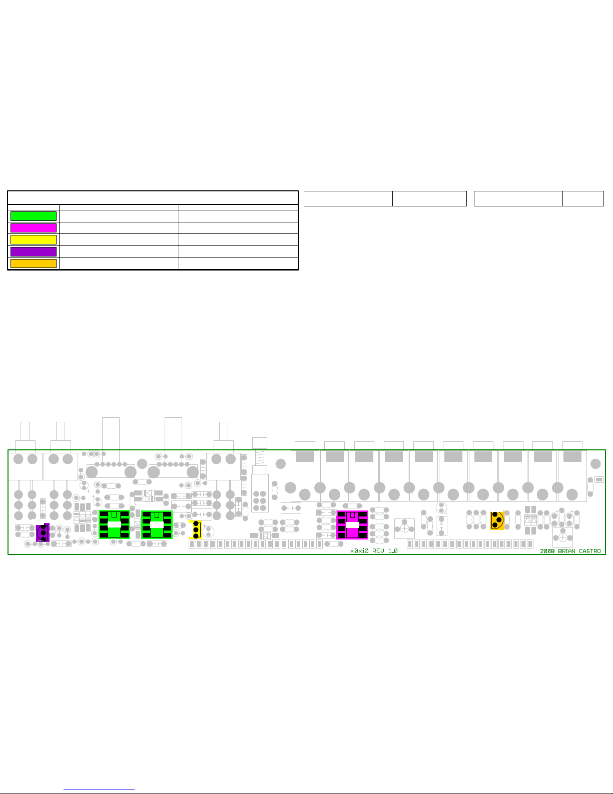
The parts-highlighting-system this document uses should make it a little easier to find the correct locations for all PCB components. Work through each page, installing the
devices listed on each page until all components are fitted. Take note of any special instructions and pictures.
Any multi-instruction pages should be followed in the order - Top left, Bottom left, Top right, Bottom right.
OVERVIEW
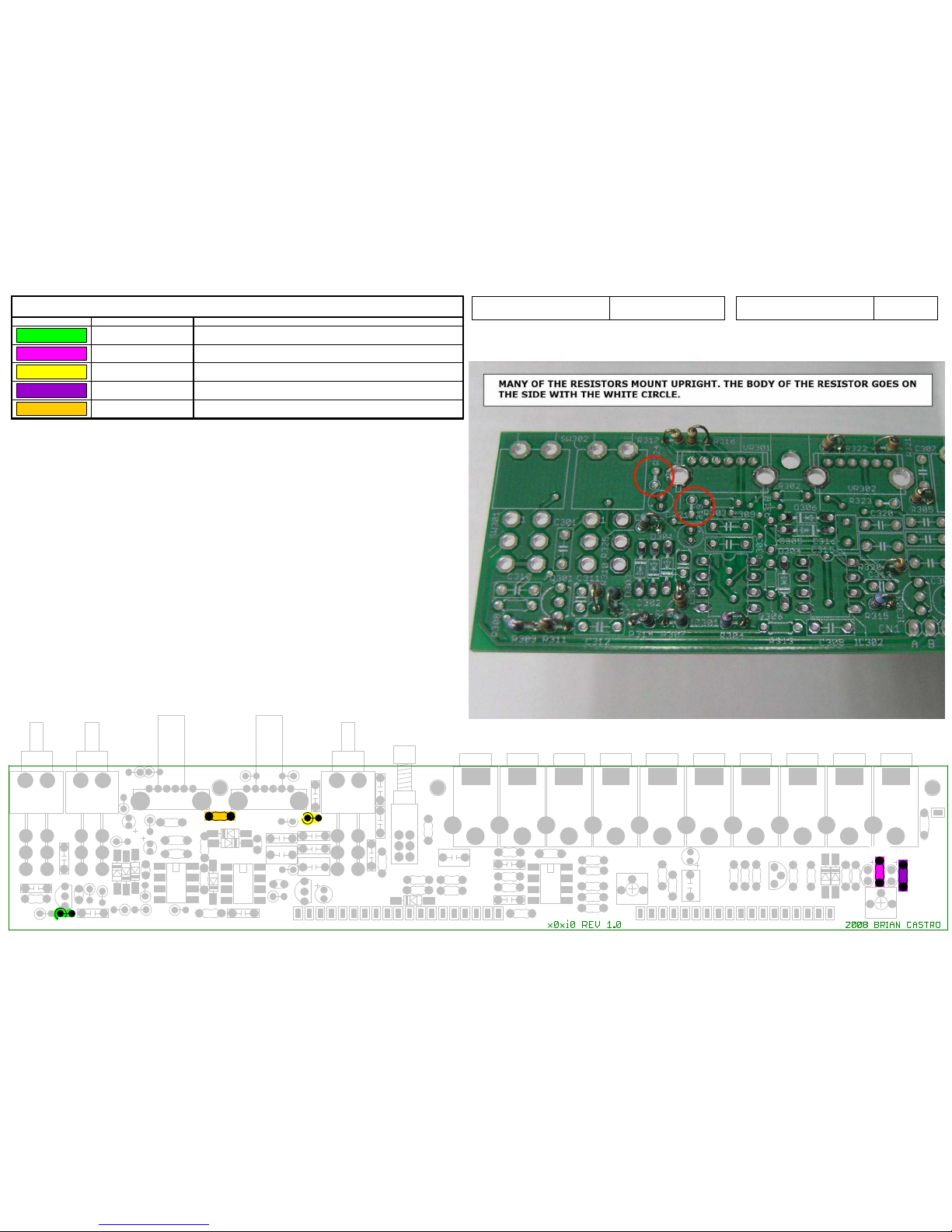
Resistor colour codes:It is recommended to check resistor values before fitting.
Ladyada's website is a great resource:-
http://www.ladyada.net/library/metertut/resistance.html
Introduction
Tools
Soldering Iron
Solder
Diagonal cutters
Wire stripper
#0 & #00 phillips screwdrivers
De-soldering tool or soldering braid
Multimeter
A good pc board holder will make things go a bit easier. It is not completely necessary but if you have one or have access to one it will help.
60/40 .031” Rosin core solder is recommended. 63/37 or 60/40 no clean solder is also OK. Lead free solder is not recommended.
Stuffing the PCB is straight forward but it is recommended to follow the steps here, it will make things easier in the long run. It will take approx. 3 hours to follow the
steps and stuff the PCB.
Preperation
1
2
3
4
SW301 SW302
SW303
J310 J309 J308 J307 J306 J305 J304 J303 J302 J301
VR301
VR302
IC301
IC302 IC304
TM302
TM301
Q302
SW304
Q301
C329
C311
C302
C330
C313
C321
C314
C322
C17
R309
R311
R314
R307
R304
R315
R325
R317
R316
R322
R321
R305
R323
R301
R310
R312
R324
D303
D302
D301
D304
D307
D308
D309
D306
D305
C310
C327
C306
C315
C304
C305
C320
C308
C323
C319
C317
C318
C307
C301
C328
C312
R308
C303
C309
R302
R341
C324
R337
R336
R335
R334
R333
R339
C325
R345
R346
R347
R344
R340
R338
C326
R313
R318
R349
R343
R342
R350
R326
R328
R327
R329
R351
R348
C316
R330
R331
R332
FIX2
FIX1 FIX3
A
B
C
CDE
F
G
HIICC
J KLM
N
N
O
C
P
QRS
T
U
U
V
V
W
X
YZAADC
BB
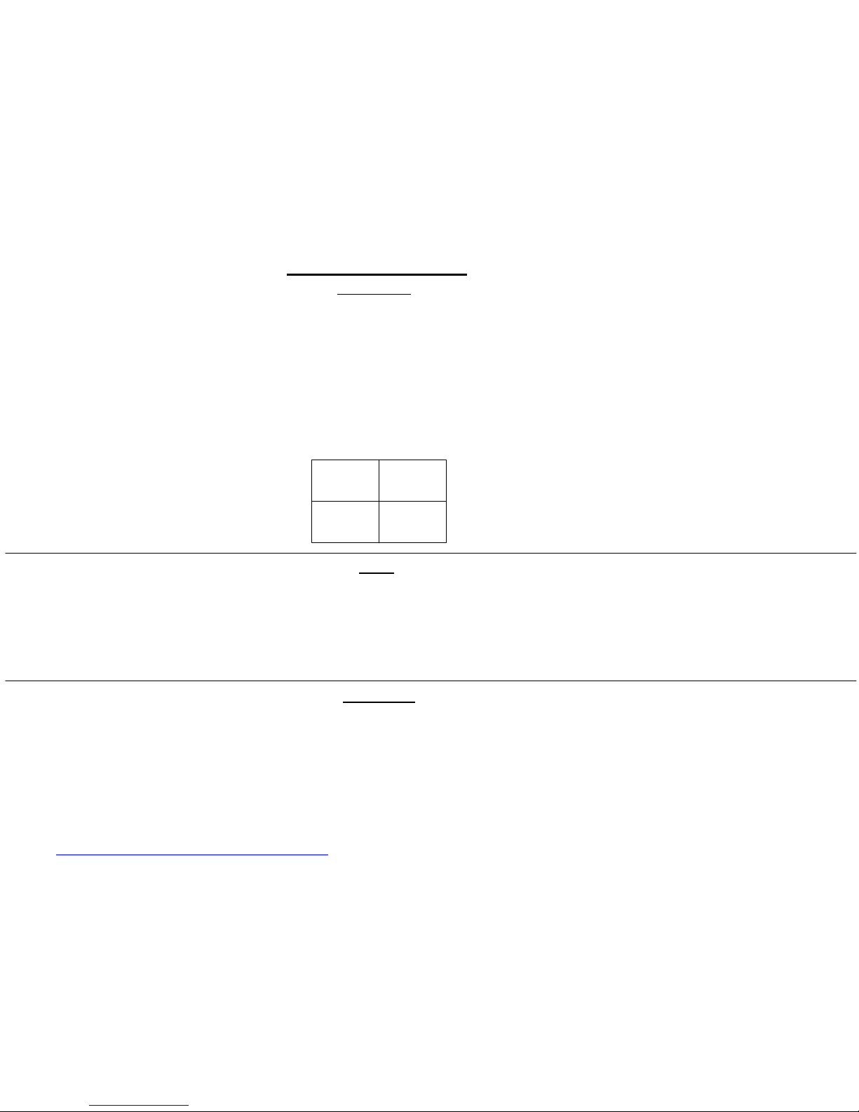
Diodes
Color Part Number Reference
1N4148
D301-D307, D309
1N5237
D308
1.06Instruction Ver.x0xioProduct Name
SW301 SW302
SW303
J310
J309
J308
J307
J306
J305
J304
J303
J302
J301
VR301
VR302
IC301
IC302 IC304
TM302
TM301
Q302
SW304
Q301
C329
C311
C302
C330
C313
C321
C314
C322
C17
R309
R311
R314
R307
R304
R315
R325
R317
R316
R322
R321
R305
R323
R301
R310
R312
R324
D303
D302
D301
D304
D307
D308
D309
D306
D305
C310
C327
C306
C315
C304
C305
C320
C308
C323
C319
C317
C318
C307
C301
C328
C312
R308
C303
C309
R302
R341
C324
R337
R336
R335
R334
R333
R339
C325
R345
R346
R347 R344
R340
R338
C326
R313
R318
R349
R343
R342
R350
R326
R328
R327
R329
R351
R348
C316
R330
R331
R332
FIX2
FIX1
FIX3
A
B
C
C
D
E F
GHIICCJ
KLMNN
O
C
P
QRS
T
U
U
V
V
W
X
YZAADC
BB
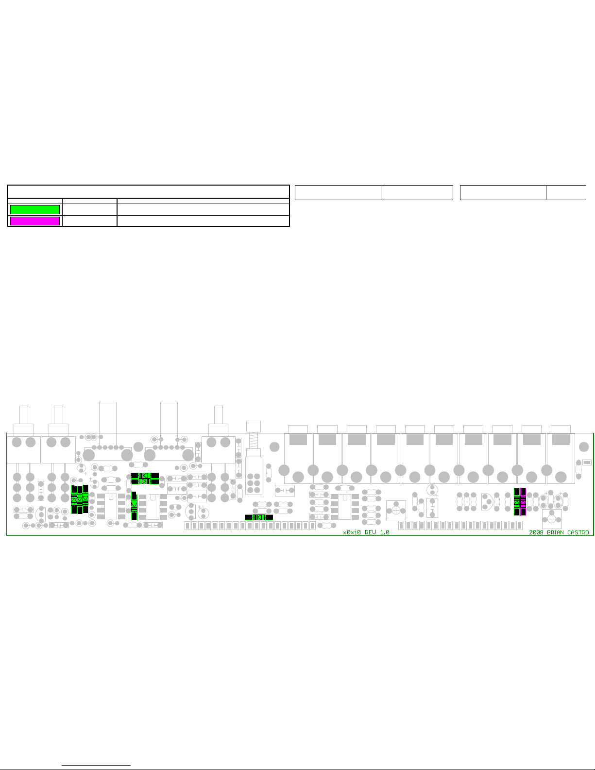
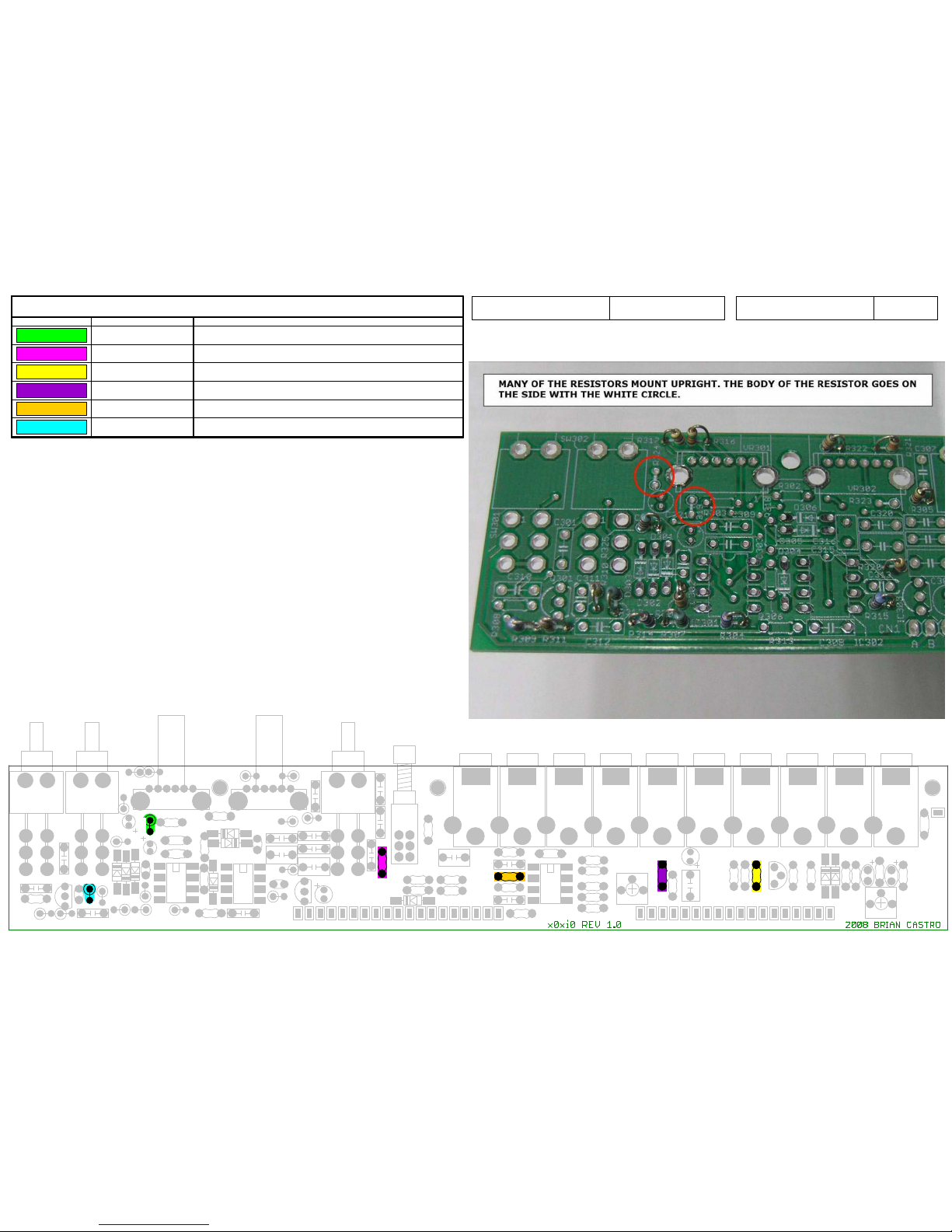
Resistors
Color Part Number Reference
2.2k_1/8W
R320-R321, R327
1k_1/8W
R318, R324-R325, R346
6.8k_1/8W
R322-R323
1M_1/8W
R301, R308
47k_1/8W
R313, R331
Product Name x0xio Instruction Ver. 1.06
SW301
SW302
SW303
J310 J309 J308 J307 J306 J305 J304 J303 J302 J301
VR301
VR302
IC301
IC302
IC304
TM302
TM301
Q302
SW304
Q301
C329
C311
C302
C330
C313
C321
C314
C322
C17
R309
R311
R314
R307
R304
R315
R325
R317
R316
R322
R321
R305
R323
R301
R310
R312
R324
D303
D302
D301
D304
D307
D308
D309
D306
D305
C310
C327
C306
C315
C304
C305
C320
C308
C323
C319
C317
C318
C307
C301
C328
C312
R308
C303
C309
R302
R341
C324
R337
R336
R335
R334
R333
R339
C325R345
R346
R347 R344
R340
R338
C326
R313
R318
R349
R343
R342
R350
R326
R328
R327
R329
R351
R348
C316
R330
R331
R332
FIX2
FIX1
FIX3
A
B
C
CDE
F
G
HIICC
J KLM
N
N
O
C
P
QRS
TUU
V
V
W
X
Y Z AA
D
C
BB
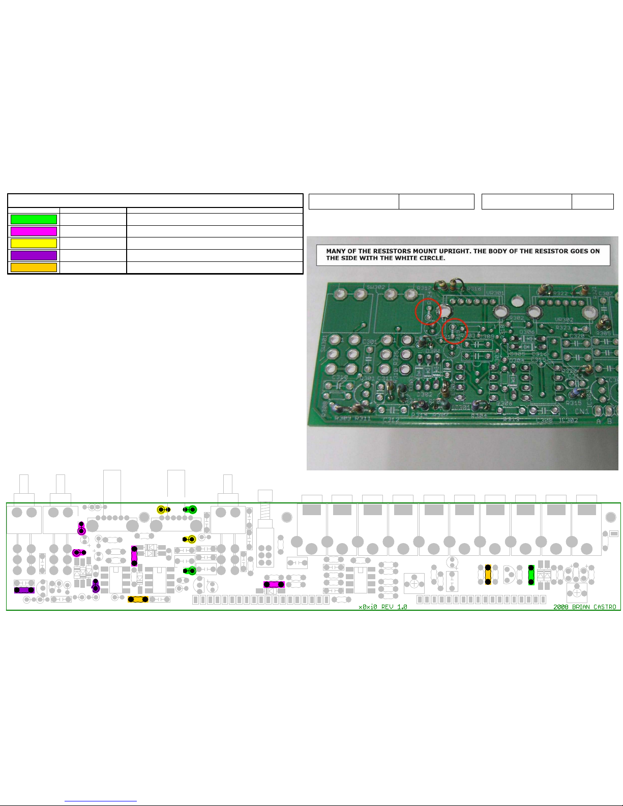
Resistors
Color Part Number Reference
22k_1/8W
R317, R326, R333-R334, R336, R338-R339,
R343-R345
100k_1/8W
R309, R314-R316, R329, R332, R335, R337,
R347, R349
10k_1/8W
R303-R304, R306-R307, R312, R328, R341
Product Name x0xio Instruction Ver. 1.06
SW301
SW302
SW303
J310
J309
J308
J307
J306
J305
J304
J303
J302
J301
VR301
VR302
IC301
IC302 IC304
TM302
TM301
Q302
SW304
Q301
C329
C311
C302
C330
C313
C321
C314
C322
C17
R309
R311
R314
R307
R304
R315
R325
R317
R316
R322
R321
R305
R323
R301
R310
R312
R324
D303
D302
D301
D304
D307
D308
D309
D306
D305
C310
C327
C306
C315
C304
C305
C320
C308
C323
C319
C317
C318
C307
C301
C328
C312
R308
C303
C309
R302
R341
C324
R337
R336
R335
R334
R333
R339
C325
R345
R346
R347 R344
R340
R338
C326
R313
R318
R349
R343
R342
R350
R326
R328
R327
R329
R351
R348
C316
R330
R331
R332
FIX2
FIX1
FIX3
A
B
C
C
D
E F
GHIICCJ
KLMNN
O
C
P
QRS
T
U
U
V
V
W
X
Y Z AA
D
C
BB
Resistors
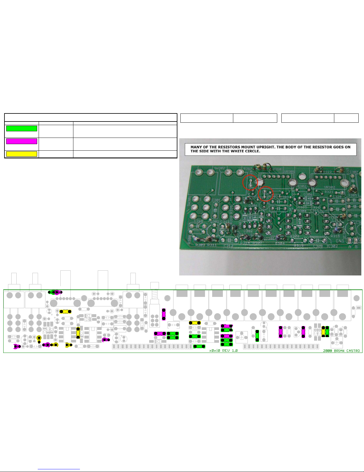
Color Part Number Reference
22_Ohm_1/8W
R311
150_Ohm_1/8W
R350
470_Ohm_1/8W
R305
1.24k_1/8W
R351
3.3k_1/8W
R302
Product Name x0xio Instruction Ver. 1.06
SW301
SW302
SW303
J310
J309
J308
J307
J306
J305
J304
J303
J302
J301
VR301
VR302
IC301
IC302 IC304
TM302
TM301
Q302
SW304
Q301
C329
C311
C302
C330
C313
C321
C314
C322
C17
R309
R311
R314
R307
R304
R315
R325
R317
R316
R322
R321
R305
R323
R301
R310
R312
R324
D303
D302
D301
D304
D307
D308
D309
D306
D305
C310
C327
C306
C315
C304
C305
C320
C308
C323
C319
C317
C318
C307
C301
C328
C312
R308
C303
C309
R302
R341
C324
R337
R336
R335
R334
R333
R339
C325
R345
R346
R347 R344
R340
R338
C326
R313
R318
R349
R343
R342
R350
R326
R328
R327
R329
R351
R348
C316
R330
R331
R332
FIX2
FIX1
FIX3
A
B
C
C
D
E F
GHIICCJ
KLMNN
O
C
P
QRS
T
U
U
V
V
W
X
Y Z AA
D
C
BB
Resistors
Color Part Number Reference
4.7k_1/8W
R319
15k_1/8W
R348
33k_1/8W
R330
150k_1/8W
R342
220k_1/8W
R340
470k_1/8W
R310
Product Name x0xio Instruction Ver. 1.06
SW301
SW302
SW303
J310 J309 J308 J307 J306 J305 J304 J303 J302 J301
VR301
VR302
IC301 IC302
IC304
TM302
TM301
Q302
SW304
Q301
C329
C311
C302
C330
C313
C321
C314
C322
C17
R309
R311
R314
R307
R304
R315
R325
R317
R316
R322
R321
R305
R323
R301
R310
R312
R324
D303
D302
D301
D304
D307 D308
D309
D306
D305
C310
C327
C306
C315
C304
C305
C320
C308
C323
C319
C317
C318
C307
C301
C328
C312
R308
C303
C309
R302
R341
C324
R337
R336
R335
R334
R333
R339
C325R345
R346
R347 R344
R340
R338
C326
R313
R318
R349
R343
R342
R350
R326
R328
R327
R329
R351
R348
C316
R330
R331
R332
FIX2
FIX1
FIX3
A
B C
C D E
F
G
H I I C C J KLM N N
O
C P
Q
R S
T
U U
V
V
W X
Y
Z
AA
D C
BB
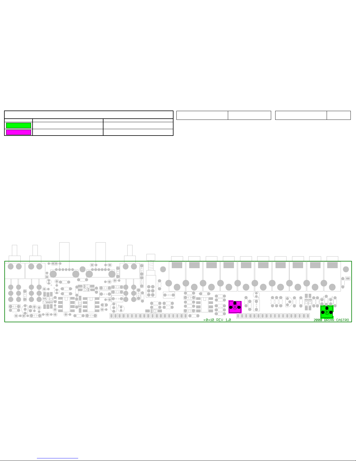
Trimmers
Color Part Number Reference
100_TRIMPOT
TM302
20K_TRIMPOT
TM301
1.06Instruction Ver.x0xioProduct Name
SW301
SW302
SW303
J310 J309 J308 J307 J306 J305 J304 J303 J302 J301
VR301
VR302
IC301 IC302
IC304
TM302
TM301
Q302
SW304
Q301
C329
C311
C302
C330
C313
C321
C314
C322
C17
R309
R311
R314
R307
R304
R315
R325
R317
R316
R322
R321
R305
R323
R301
R310
R312
R324
D303
D302
D301
D304
D307 D308
D309
D306
D305
C310
C327
C306
C315
C304
C305
C320
C308
C323
C319
C317
C318
C307
C301
C328
C312
R308
C303
C309
R302
R341
C324
R337
R336
R335
R334
R333
R339
C325R345
R346
R347 R344
R340
R338
C326
R313
R318
R349
R343
R342
R350
R326
R328
R327
R329
R351
R348
C316
R330
R331
R332
FIX2
FIX1
FIX3
A
B C
C D E
F
G
H I I C C J KLM N N
O
C P
Q
R S
T
U U
V
V
W X
Y
Z
AA
D C
BB
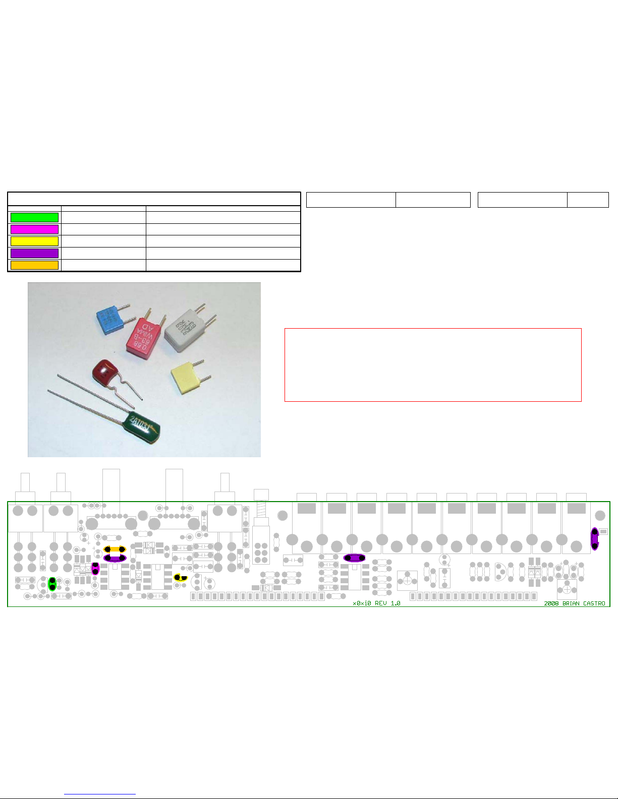
Ceramic Caps
Color Part Number Reference
270pF_CERAMIC
C311
47pF_CERAMIC
C302
100pF_CERAMIC
C313
0.1uF_CERAMIC
C303, C324, C328
680pF_CERAMIC
C309
The ceramic capacitors also have their value marked on
them. The (3) 0.1uF ceramics have 5mm spacing and
say 104 on them. The rest of them have 3mm spacing.
The 47pF is marked 470, the 270pF is marked 271, and
the 100pF is marked 101.
1.06Instruction Ver.x0xioProduct Name
SW301
SW302
SW303
J310 J309 J308 J307 J306 J305 J304 J303 J302 J301
VR301
VR302
IC301 IC302
IC304
TM302
TM301
Q302
SW304
Q301
C329
C311
C302
C330
C313
C321
C314
C322
C17
R309
R311
R314
R307
R304
R315
R325
R317
R316
R322
R321
R305
R323
R301
R310
R312
R324
D303
D302
D301
D304
D307 D308
D309
D306
D305
C310
C327
C306
C315
C304
C305
C320
C308
C323
C319
C317
C318
C307
C301
C328
C312
R308
C303
C309
R302
R341
C324
R337
R336
R335
R334
R333
R339
C325R345
R346
R347 R344
R340
R338
C326
R313
R318
R349
R343
R342
R350
R326
R328
R327
R329
R351
R348
C316
R330
R331
R332
FIX2
FIX1
FIX3
A
B C
C D E
F
G
H I I C C J KLM N N
O
C P
Q
R S
T
U U
V
V
W X
Y
Z
AA
D C
BB
ICs and Transistors
Color Part Number Reference
OP275
IC301-IC302
TLC2272
IC304
TLE2426
IC303
2N5088
Q301
BC549B
Q302
1.06Instruction Ver.x0xioProduct Name
 Loading...