

Page 1
Xorcom USA
2012 W. Lone Cactus Drive
Phoenix, AZ 85027 USA
Tel: 1-866-XORCOM1
info.usa@xorcom.com
www.xorcom.com
Xorcom Ltd.
Teradyon, POB 60
D.N. Misgav 20179, Israel
Tel: +972-4-9951999
info@xorcom.com
Continuous yellow
Indicates that the port is configured as NT
Two fast green blinks
Indicates that E1/T1 layer 1 is active
Single yellow blink
Indicates that ISDN PRI layer 2 is active
1)
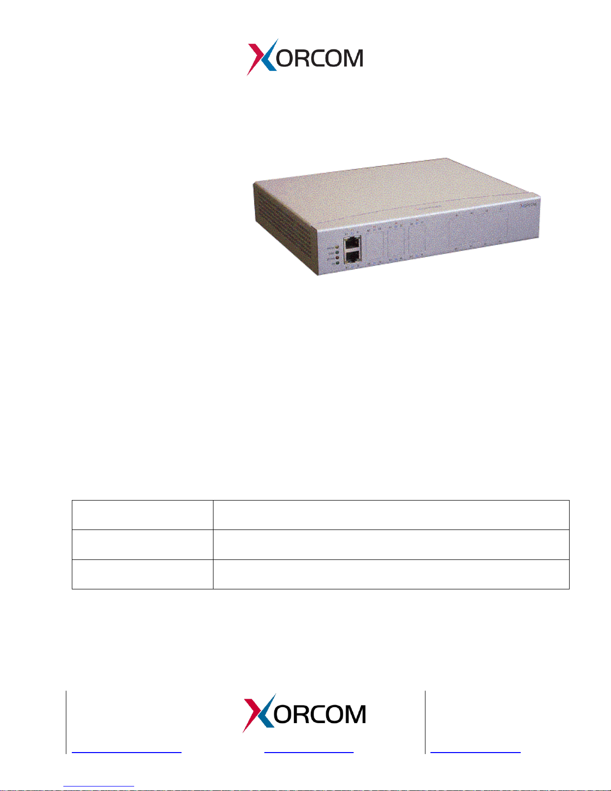
Astribank PRI - Quick Start Guide
Port PINs Layout
The Astribank PRI unit has two
RJ-45 sockets for each PRI
port. Both sockets are
permanently active and can be
used with any configuration
parameters.
The lower socket provides typical E1/T1 TE (CPE) side wiring:
Rx pins: 1, 2
Tx pins: 4, 5
The upper socket provides typical E1/T1 NT (Network) side-wiring:
Rx - pins 4, 5
Tx - pins 1, 2
Port LED Indicators
The green LED of the lower socket indicates the line status when the port is
configured as TE. The yellow LED of the upper socket shows the line status when the
port is configured as NT.
Table 1: Port Status LEDs
1)
More precisely, this indicates that there is some Layer 2 messages exchange.
Sometimes it doesn't mean that the Layer 2 connection has been established.
Page 2

Astribank PRI - Quick Start Guide Page 2 of 4
Xorcom USA
2012 W. Lone Cactus Drive
Phoenix, AZ 85027 USA
Tel: 1-866-XORCOM1
info.usa@xorcom.com
www.xorcom.com
Xorcom Ltd.
Teradyon, POB 60
D.N. Misgav 20179, Israel
Tel: +972-4-9951999
info@xorcom.com
Port Parameter
Configuration File
Configuration Parameter
E1/T1 selection
Zaptel Init Configuration File
1)
XPP_PRI_SETUP
NT/TE selection
a) Zaptel Init Configuration File
1)
b) zapata.conf
XPP_PRI_SETUP
Clock source, framing
type and line encoding
zaptel.conf
span (see Asterisk
documentation)
Configuring an Astribank PRI
Each Astribank PRI port may be configured to work as E1 or T1, TE or NT by changing
the Astribank driver and Asterisk parameters. No jumpers or DIP switches need to be
changed. The following table shows where each Astribank ISDN PRI port parameter is
configured.
Table 2: Astribank ISDN PRI Port Parameter Configuration
1)
The Zaptel Init Configuration File is either:
/etc/default/zaptel (on Debian, Ubuntu, etc.)
/etc/sysconfig/zaptel (on RedHat, CentOS etc).
The information defined in this file is used by Zaptel and some Zaptel utilities. For
example, the “genzaptelconf” utility uses information from XPP_PRI_SETUP for
automatic Asterisk and Zaptel configuration building. Also, the Astribank PRI driver
initializes the ports for E1 or T1 functionality according to the XPP_PRI_SETUP
parameter.
If the XPP_PRI_SETUP parameter is not defined, then each PRI port is assumed to be
of default type E1 TE (CPE).
Format of the XPP_PRI_SETUP
The format of the XPP_PRI_SETUP parameter is as follows:
XPP_PRI_SETUP='<port_address=port_type> <port_address=port_type>'
The <port_address> and the <port_type> are explained in the following sections.
Port Address
The <port_address> may be represented by using either the Astribank XPP protocol
logical XBUS number or the physical USB connector number.
When using the logical XBUS numbers in the <port_address> expression, use the
following syntax:
NUM/XBUS-mm/XPD-nn
Page 3

Astribank PRI - Quick Start Guide Page 3 of 4
Xorcom USA
2012 W. Lone Cactus Drive
Phoenix, AZ 85027 USA
Tel: 1-866-XORCOM1
info.usa@xorcom.com
www.xorcom.com
Xorcom Ltd.
Teradyon, POB 60
D.N. Misgav 20179, Israel
Tel: +972-4-9951999
info@xorcom.com
The value for mm - is the XBUS number and the value for nn - is the XPD number (see
the “Terminology” topic at the end of this document.)
When using a physical USB connector number in the <port_address> expression, use
the following syntax:
CONNECTOR/usb..../XPD-nn
The value for usb... is the USB connector identifier and the value for nn is the XPD
number.
You can get the USB connector identifier from verbose output of the zaptel_hardware
utility when the Zaptel drivers are loaded. For example:
# zaptel_hardware -v
usb:004/004 xpp_usb+ e4e4:1152 Astribank-multi FPGA-firmware
LABEL=[usb:0000108] CONNECTOR=usb-0000:00:03.3-4
XBUS-00/XPD-00: E1_TE Span 1 ZAPTEL-SYNC
XBUS-00/XPD-01: E1_TE Span 2
XBUS-00/XPD-10: FXS Span 3
XBUS-00/XPD-20: FXS Span 4
Port Type
The <port_type> is the port mode and port function group separated by a comma, for
example: E1,TE or T1,NT. Please note that port mode and the function group may
be written in any order. For example, the following will provide the same result:
T1,TE and TE,T1
Now you can define:
XPP_PRI_SETUP='CONNECTOR/usb-0000:00:03.3-4/XPD-00=T1,TE'
The following wild card characters can be used in the port address expression:
* matches zero or more characters.
? matches one character
[xyz] - any of 'x', 'y', or 'z'.
Configuration Examples
To define all PRI ports for T1 with TE (CPE) function groups:
XPP_PRI_SETUP='NUM/*=T1,TE'
To define the first port to be E1 TE and the second port to be E1 NT:
XPP_PRI_SETUP='NUM/XBUS-00/XPD-00=E1,TE NUM/XBUS-00/XPD-01=E1,NT'
Page 4

Astribank PRI - Quick Start Guide Page 4 of 4
Xorcom USA
2012 W. Lone Cactus Drive
Phoenix, AZ 85027 USA
Tel: 1-866-XORCOM1
info.usa@xorcom.com
www.xorcom.com
Xorcom Ltd.
Teradyon, POB 60
D.N. Misgav 20179, Israel
Tel: +972-4-9951999
info@xorcom.com
Terminology
span
Zaptel breaks the channels it knows about into logical units called spans. A port in an
E1/T1/ISDN card is usually a span. A whole analog card is also a span. You can see the
list of spans as the list of files under /proc/zaptel directory or in the output of the
zttool utility.
XBUS
Denotes an Astribank device.
XPD
Basically, this is a logical unit of an Astribank device. It will be registered in Zaptel as
a single span. This can be either an analog (FXS or FXO) module or a single port in
case of a BRI or a PRI module.
 Loading...