

5·100·12
COMPUTER
ASSEMBLY
AND
OPERATING
INSTRUCTIONS
FORWARO
This
Chapter
and
Chapter
manual
Ona,
tasting
Two,
information
up,
up
systems
and
running
Chapter
instructions
Chapter
ordered
with
is
ASSEMBLY,
instructions.
GENERAL
on
utilities,
Three,
for
Four,
the
divided
systems
correctly.
BOARD
each
CP/M,
system.
into
three
contains
OPERATING
hardware
other
and
OPERATING
three
the
of
contains
chapters
initial
the
PROCEDURES,
software.
end
information
MANUALS
contains
computer
the
CP/M
your
for
unpacking,
consists
It
to
boards.
reference
convenience.
assembly,
technical
of
includes
your
get
the
operating
manuals
power
system
if
1
**************TABLE
OF
CONTENTS**************
CHAPTER
1.0
1.1
1.2
1.3
1.4
1.
1.6
1.
1.8
1.9
1.10
1.11
1.12
CHAPTER
2.1
2.2
2.3
2.4
2.5
2.6
2.7
2.8
2.9
2.10
2.11
2.12
2.13
2.14
2.15
2.16
2.17
2.18
2.19
ONE -ASSEMBLY
UNPACKING
INSPECTION
CABINET
POWER
DISK
DISK
5
INITIAL
7
BOARD
SERIAL
COMPUTER
DISK
FINAL
DRIVE
ASSEMBLY
TRANSFORMER
DRIVE
DRIVE
POWER
INSTALLATION
TERMINAL
TERMINAL
OPERATION
CLOSE
NOTES
TWO -GENERAL
SHOCK
HARD
POWER
MONITOR
DISK
BOOTING
BACKING
SAFETY
SERVICE
DISK A DISK
MODIFYING
CP/M
DSYSGEN
DSYSGEN
MP/M
MEANING
SUB
MEMORY
AND
TILT
DISK
SYSTEMS
UP
COMMANDS
BOOT
COMMANDS
THE
UP
PRECAUTIONS
POLICY
XOR
B -
SYSTEM
AND
OPERATING
OPERATING
STEP-BY-STEP
II
SYSTEM
OF
TYPE
FILES
MAP
APPENDICES
PRINTER
CENTRONICS
DIABLO
EPSON
EPSON
ANADEX
TEXAS
DRIVE
SERIAL
MX-80
MX-80
9500
INSTRUMENTS
OPTIONS
CONNECTIONS
OPTIONS
MOUNTING
ON
CONNECTION
CHECKS
CHECKS
OUT
OPERATING
SENSORS
OPERATING
DISK
UTILITIES
SOURCE
GENERATING
SYSTEMS
INSTRUCTIONS
GENERATION
BITS IN
FOR
CODE
SYSTEM
DRIVERS
INTERFACE
SERIAL
PARALLEL
SERIAL
QUME
DT-8
PROCEDURES
SYSTEM
DISK
PROCEDURE
BYTE
BUILDING
SERIAL
PAGE
3
3
3
3
4
4
4
5
5
5
5
6
6
7
8
8
9
10
10
12
14
15
16
20
24
28
32
34
41
43
46
47
48
50
51
52
54
56
2
US
MICRO
SALES
1.0
UNPACKING
We
keep
boxes
return
within
and
your
Please
Report
not
Do
shipper
responsible
1.1
INSPECTION
Inspect
broken
Remove
if
have
shipped
United
packing
computer
unpack
visable
any
attempt
and
for
wires
necessary.
to
having
shipping
Sl
the
wire
or
your
Parcel
materials,
us.
to
carefully
damage
repair
damage
MOD
strands
CHAPTER
ASSEMBLY
Sl00-12
shipping
and
your
to
any
inspected.
damage
assembly
lodged
ONE
2
in
requirements.
should
inspect
local
equipment
~
loose
for
in
separate
ever
it
for
shippers
before
MICRO
US
~
the
boxes
be
shipping
any
screws,
connector
bus
in
Please
necessary
claims
calling
SALES
connectors,
order
keep
damage.
office.
your
is
area.
to
all
to
not
1.2
CABINET
Remove
rear
front
they
on
panels
and
are
each
J;hillips
right
the
to
Install
install
positioned
1.3
POWER
Refer
connections.
reset
plug,
identified
ASSEMBLY
cabinet
the
from
rear
wired
side
screws
within
panels
together.
of
install
side.
the
rubber
to
4
the
the
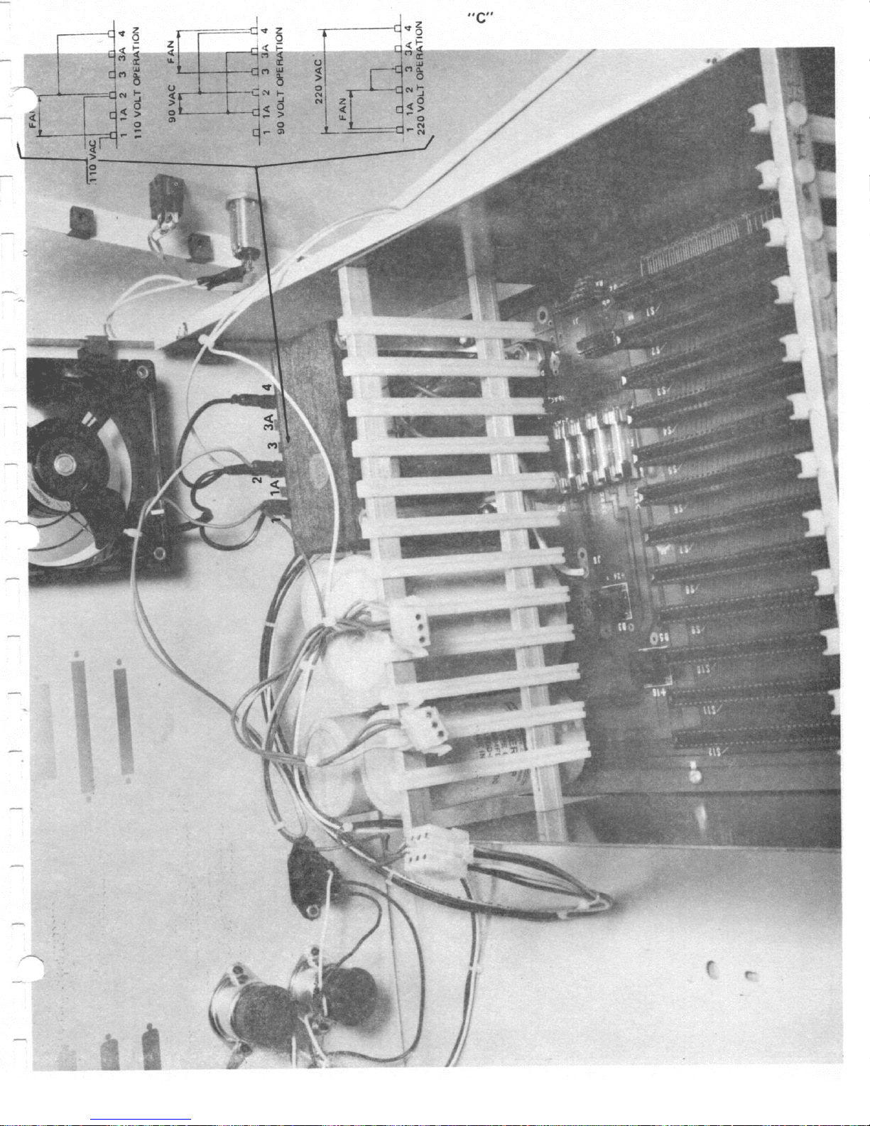
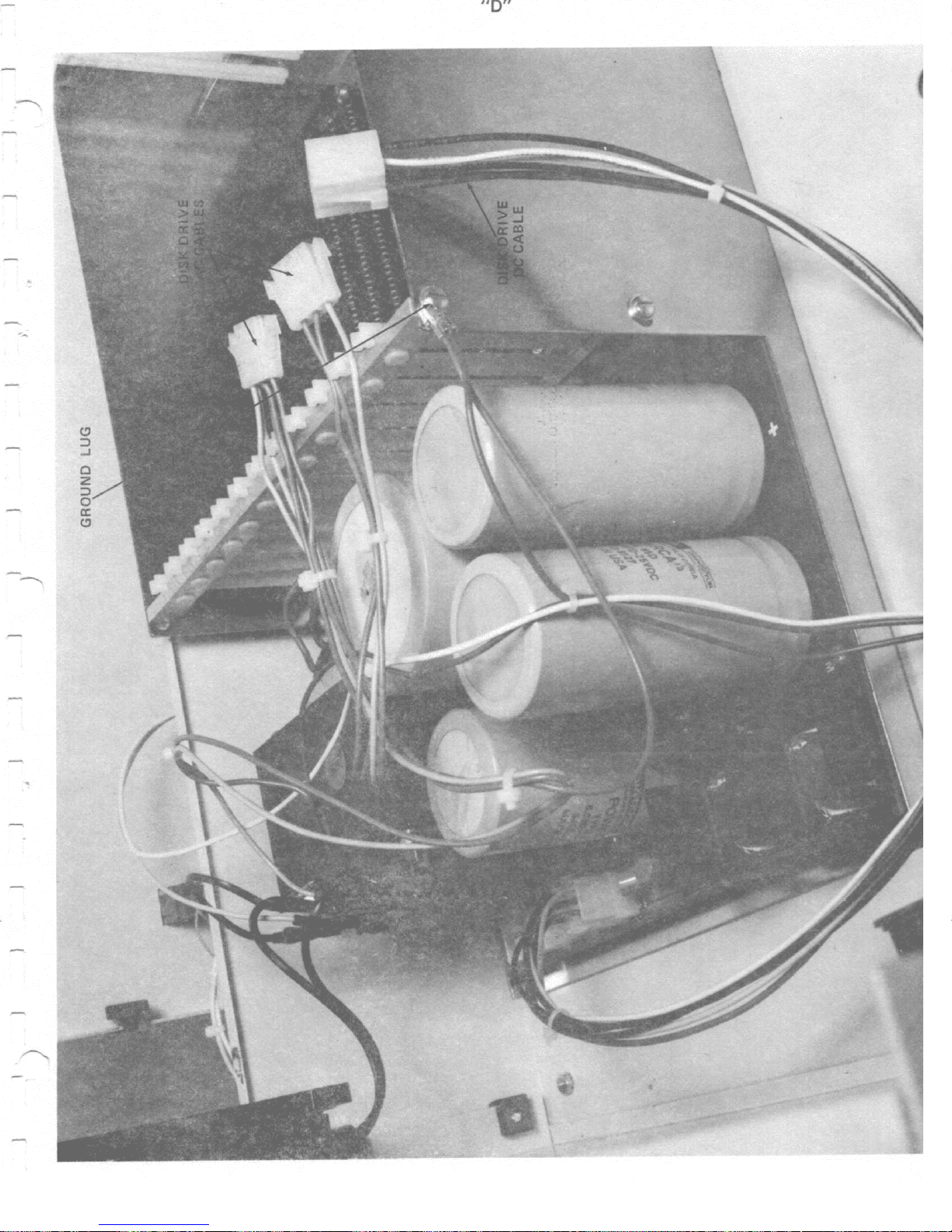
TRANSFORMER
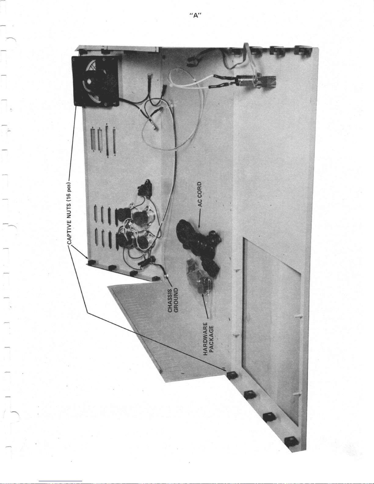
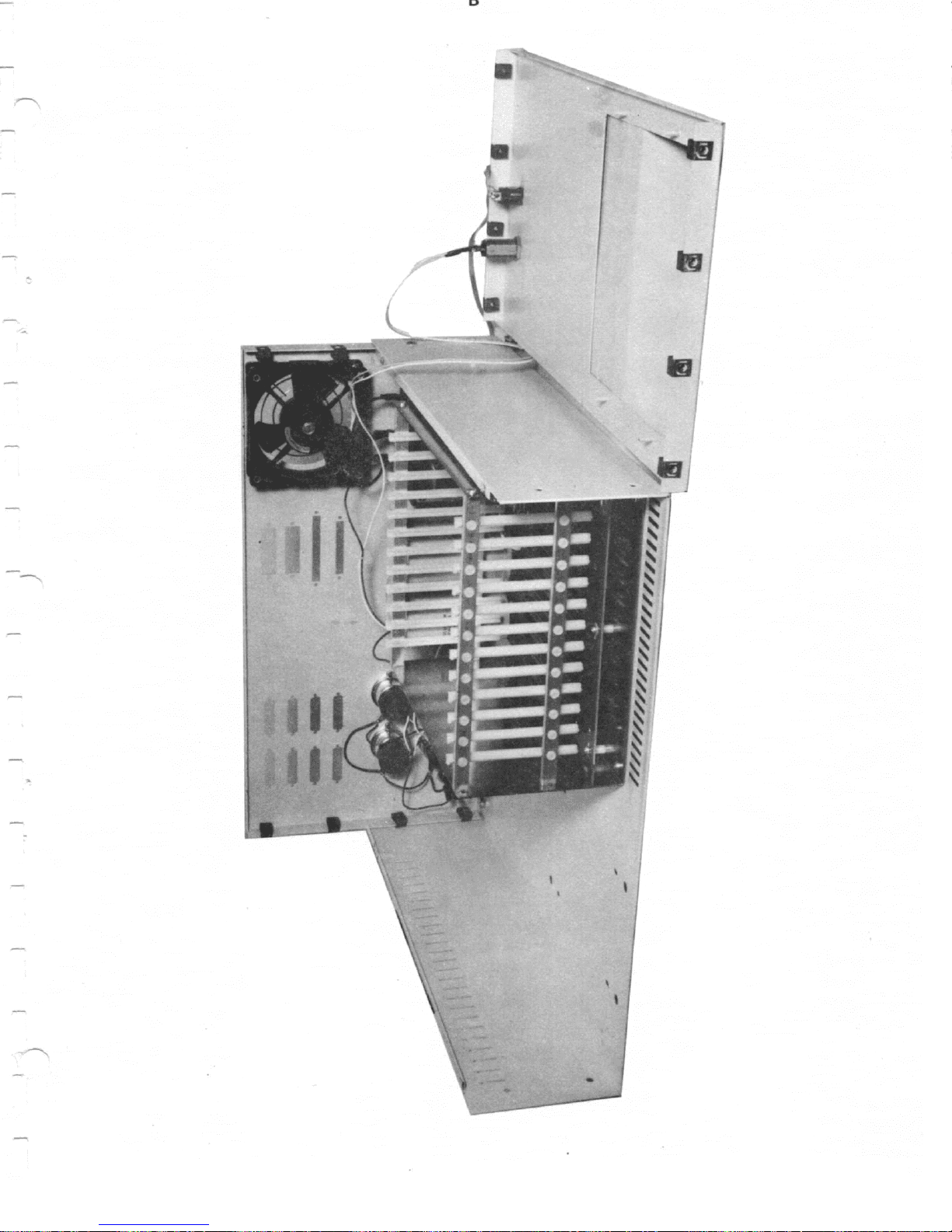
photos
to
The
identified
with
a
the
MOD
Sl
rear.
wiring
yellow
and
top
bottom
the
the
on
See
front
the
assembly.
feet.
(Refer
WIRING
"C"
with
dot.
set
bench
photo
and
rear
to
"D"
&
shown
red
a
(Refer
aside.
half
in
rear
panel
Note
photo
for
is
dot,
of
position,
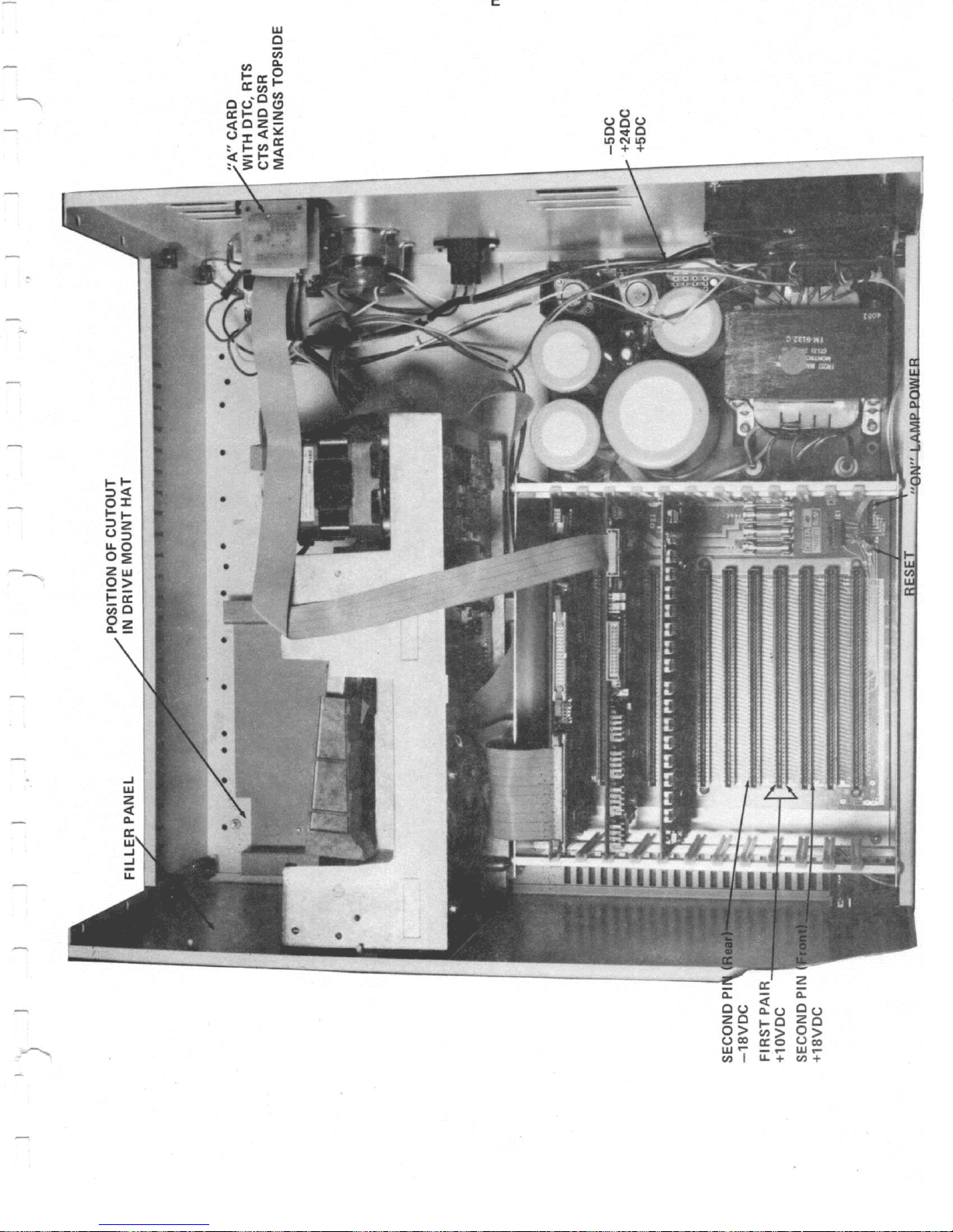
"A".
panels.
only,
the
Use
the
B.)
the
117
for
and
photo
to
Unpack
the
Install
lay
6/32
power
correct
volts.
the
E.)
the
cabinet.
be
8
Using
the
hardware
transformer
reset
front
lay
careful
captive
the
front
transformer
lamp
in
power,
Plug
and
the
as
nuts
10
f
panel
and
is
the

1.4
MICRO
DISK
If
SALES,
you
"B". Each
changes,
refer
DRIVE
are
drive
OPTIONS
installing
they
have
is
to
drive
been
labeled.
notes
shugart
pre-tested
If
you
section
801
wish
1.12
drives
and
jumpered
to
for
received
make
drive
jumper
from
as
"A:
JUmper
options.
US
and
1.5
DRIVE
Refer
the
hat
using
is
a
preliminary
determined
m::iunt.
Final
So
alignment
repositioning
elongated.
the
Close
At
AC
power
of
1/2
out
this
time
drive
transformer.
the
Sl
connections
connectors
1.6
INITIAL
Apply
and
plugging
check
voltages
to
into
line
dropout
for
are
insert
line.
at
protection
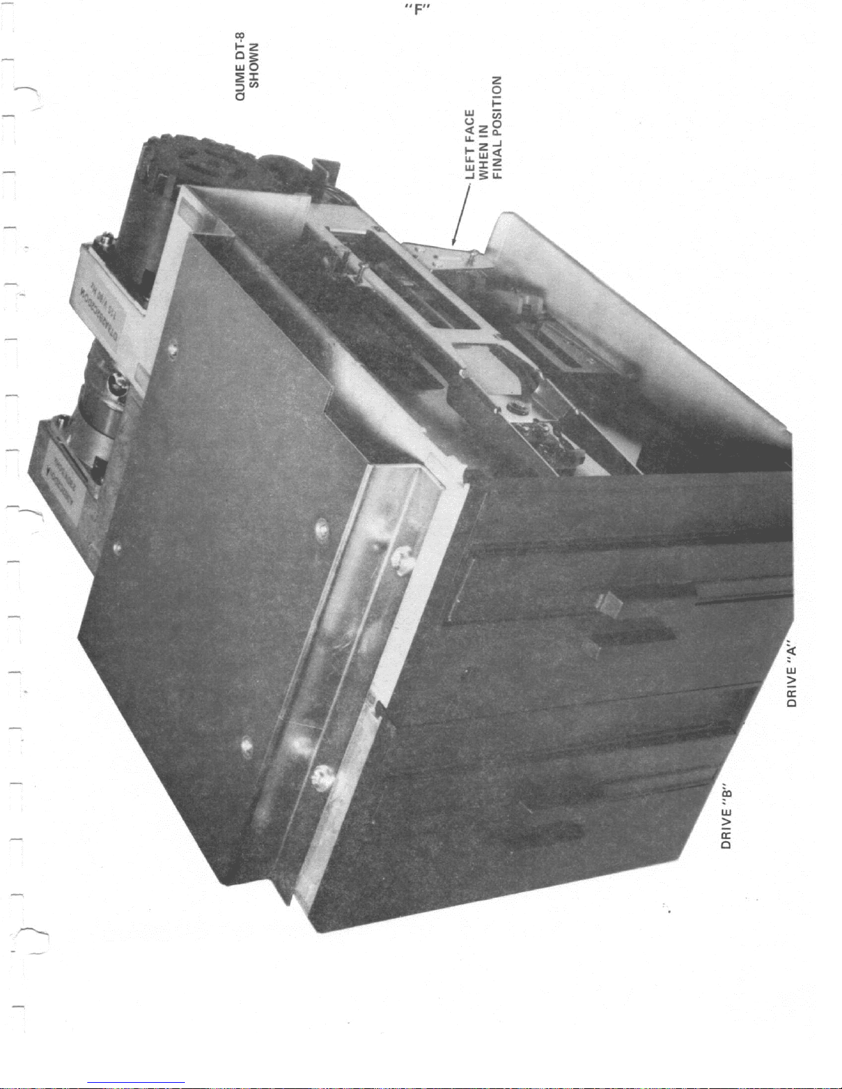
MOUNTING
to
photo"F",
the
fitting
by
drive
do
not
them
Note,
closeout
plates
are
connect
MOD
under
are
polarized.
POWER
power
it
into
proper
slightly
computer
+
The
10
Sl
volts.
8/32
hardware
panel
completely
of
because
because
plate
available
the
are
The
the
by
connecting
a
grounded
voltages
high,
boards
MOD
is
This
margin.
place
as
the
tolerance
the
drives
the
of
hat
if
you
AC
AND
piggy
green
cabinet
at
but
as
designed
allows
the
drives
and
washers
final
tighten
bottom
clearance,
are
at
no
DC
drive
backed
ground
ground
AC
cord
AC
power
points
of
correct
the
circuit
to
a
position
and
also
the
can
mounting
only
charge
power
at
terminals
wire
wire.
to
outlet.
shown
run
better
upside
provided.
on
how
screws
be
accomplished
holes
it
is
installing
from
US
cables.
connects
Note
back
of
in
polarity,
loads
the
will
S-100
power
down and mount
the
many
at
Note,
hat
drives
this
will
time.
this
be
you
by
best
one
MICRO
1
and
to
both
the
Use a
photo
it
bring
+
line
have
to
the
meter
may
8
surge
been
install
drive.
SALES.
Note
3
of
the
the
corner
power
computer
to
"E".
be
If
ok
them
voltage
and
1.7
BOARD
Visually
foreign
Etioto "G"
recommend
Install
Install
keyed,
in
green
install
place.
dot
Install
making
any
easier
Use
the
serial
port.)
INSTALLATION
inspect
matter
for
the
the
the
the
CPU
CPU
on
Disk
serial
the
Install
denotes
the
special
to
make
4/40
these
hardware
terminal
all
the
boards.
correct
controller
and memory
cable
50P
data
the
SOP
pin
50.
RS
232
adapters
jumper
changes
provided.
port
and "A"
computer
Remove
positioning
be
boards,
at
the
cable
cable
refer
at
at
to
at
changes
on
before
is
the
4
boards
if
of
the
installed
be
board,
the
Disk
the
disk
photo
the
the
"G".
cabinet
printer
installation
(Note
CP/M
for
any
necessary.
computer
sure
to
note
controller
drive.
back,
"B"
will
serial
loose
in
seat
the
card,
to
be
lister
parts,
Refer
boards.
position
firmly.
connector
and
Note,
if
you
it
will
the
cabinet.
the
printer
or
to
We
1.
is
lock
the
are
be
CP/M
,,-
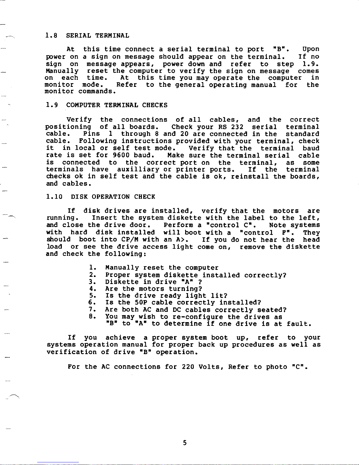
1.8
power
sign
Manually
on
monitor
monitor
SERIAL
At
on a sign
on
each
TERMINAL
this
message
time.
mode.
commands.
time
reset
connect
on
message
appears,
the
At
Refer
computer
this
to
a
serial
should
power
to
time
the
general
appear
down
verify
you
terminal
on
and
the
may
operate
operating
to
the
refer
sign
port
terminal.
on
the
manual
"B".
to
message
computer
step
for
Upon
If
no
1.9.
comes
in
the
1.9
positioning
cable.
cable.
it
rate
is
terminals
checks
and
1.10
running.
and
with
should
load
and
COMPUTER
Verify
in
local
is
connected
ok
cables.
DISK
If
close
hard
or
check
TERMINAL
the
of
Pins
Following
or
set
for
have
in
self
OPERATION
disk
boot
see
Insert
the
disk
into
the
the
1.
2.
3.
4.
5.
6.
7.
8.
drives
drive
following:
Manually
Proper
Diskette
Are
Is
Is
Are
You may
"B"
connections
all
boards.
1
through
instructions
self
9600
to
the
auxilliary
test
the
door.
installed
CP/M
drive
the
the
the
both
to
CHECKS
test
baud.
correct
and
CHECK
are
installed,
system
with
access
reset
system
in
motors
drive
SOP
cable
AC
wish
"A"
to
Check
8
and
mode.
Make
or
the
diskette
Perform
will
an
light
the
diskette
drive
turning?
ready
and
DC
to
re-configure
determine
of
all
your
20
are
provided
Verify
sure
port
printer
cable
a
boot
A>.
come
computer
"A" ?
light
correctly
cables
cables,
RS
connected
with
that
the
on
the
ports.
is
ok,
verify
with
"control
with
If
you
on,
installed
lit?
installed?
correctly
if
one
and
232
your
the
terminal
terminal,
If
reinstall
that
the
label
c•.
a
"control
do
not
remove
correctly?
the
drives
drive
the
serial
in
the
terminal,
terminal
serial
the
the
to
Note
hear
the
seated?
is
correct
terminal
standard
as
terminal
the
boards,
motors
the
systems
F".
the
diskette
as
at
fault.
check
baud
cable
some
are
left,
They
head
If
you
systems
verification
operation
For
the
achieve
of
drive
AC
connections
manual
"B"
a
proper
for
operation.
proper
for
system
back
220
Volts,
5
boot
up
up,
procedures
Refer
to
refer
photo
as
to
well
•c•.
your
as
1.11
you
FINAL
If
may
CLOSEOUT
are
you
install
satisfied
top
the
with
cabinet.
proper
operation
of
all
functions,
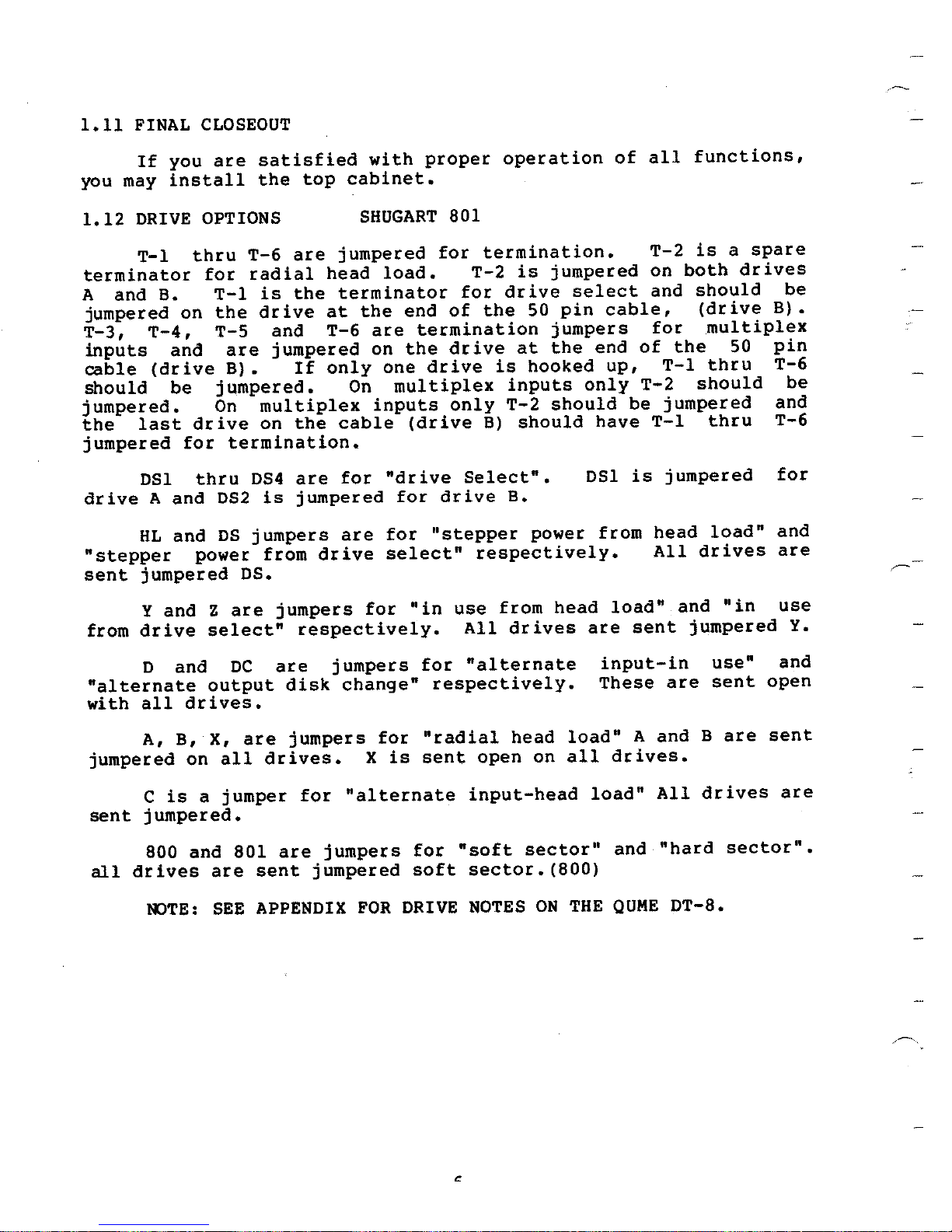
1.12
DRIVE
T-1
terminator
A and B.
jumpered on
T-3,
inputs
cable
should
T-4,
and
(drive
be
jumpered.
the
jumpered
last
for
DSl
and
drive
A
HL
and
"stepper
sent
from
jumpered
and
Y
drive
D and
"alternate
drives.
with
all
OPTIONS
are
for
T-1
the
T-5
T-6
radial
drive
are
B).
the
is
and
jumpered
If
thru
jumpered.
multiplex
On
the
drive
on
termination.
052
os
DS4
is
jumpers
thru
power from
OS.
jumpers
are
z
select"
are
DC
output
disk
SHUGART
jumpered
head
load.
terminator
the
at
are
T-6
on
only
one
On
multiplex
inputs
cable
"drive
for
are
jumpered
are
drive
for
for
select"
for
respectively.
jumpers
change"
801
termination.
for
T-2
for
the
of
end
termination
drive
the
drive
only
(drive
B)
Select".
drive
"stepper
respectively.
use
"in
All
"alternate
for
respectively.
jumpered
is
drive
pin
50
jumpers
the
at
hooked
is
inputs
should
T-2
should
B.
power from
from
head
drives
select
cable,
end
up,
only
have
DSl
load"
are
input-in
These
T-2
on
and
for
of
T-1
T-2
jumpered
be
T-1
jumpered
is
head
All
sent
are
a
is
both
should
(drive
multiplex
the
50
thru
should
thru
load"
drives
"in
and
jumpered
use"
sent
spare
drives
be
B).
pin
T-6
be
and
T-6
for
and
are
,,--
use
Y.
and
open
A, B,
jumpered
is
C
sent
jumpered.
800
drives
all
tVTE:
on
a
and
are
x,
all
jumper
801
are
SEE
jumpers
drives.
for
are
sent
jumpers
jumpered
APPENDIX
"radial
for
sent
is
X
"alternate
for
soft
DRIVE
FOR
head
open
on
input-head
"soft
sector"
sector.(800)
NOTES
ON
load"
all
load"
THE
A and B
drives.
All
and
"hard
QUME
drives
DT-8.
sent
are
are
sector".
\\
•
•
''A''
D
''C''
-
,,
.
'
&
•
n
TOPSIDE
RTS
)
)' J
DSR
OTC,
AND
CARD
CTS
~'A"
WITH
MARKINGS
+24DC
-SOC
+SOC
/
•
•
PAIR
PIN
C
I )
SECOND Pl
-18VDC
0VDC
FIRST
+1
SECOND
+18VD
...--....
.-
CIO
..:.z
o~
wO
~J:
::>
(/)
0
II
F"

0
a:
<
0
al
0
a:
<
0
al
~
I-
z
w
~
w
(.)
<
..J
Q..
0
a:
<
0
al
..J
<
(.)
Q..
~
~

----..
:..I
w
z
C[
'
'
'
/)
CHAPTER
TWO
2.1
Your
sensors
sensor
small
attached
is
glass
display
subjected
capabilities
If
any
red,
broken
write
-
initialed
Some
force
does
the
is
not
responsibility
resolving
the
shipping
shipped
section
entitled
SHOCK
computer
a
rectangular
tube
a
red
to
an
of
package
the
possible
and
dated.
XOR
computer
applied
function
payment
firm
back
to
GENERAL
ANO
TILT
system
to
the
in
the
liquid
impact
US
MICRO
that
following
shipping
to
them.
properly
of
the
for
in
your
US
MICRO
"Service
OPERATING
SENSORS
may
outside
orange
center.
inside
which
SALES
you
on
systems
and
shipper
the
damages.
local
SALES
Policy")
have
of
the
and
The
when
the
approaches
packaging
receive
the
bill
damage".
can
If
you
the
sensor
and
area
(See
PROCEDURES
been
white
sent
shipping
piece
glass
shipping
the
to
carton(s).
of
tube
carton
shock
materials.
has
shock
of
This
lading:
sensors
statement
become damaged
should
you
A
BEFORE
RMA
find
has
to
come
claim
the
Procedure
that
been
must
equipment
you
with
paper
is
designed
which
"Shock
if
the
broken,
to
agreement
be
filed
in
shock
This
with
to
has
been
absorption
are
sensor
should
be
excessive
system
it
on
with
can
a
be
later
a
is
The
arrow-shaped
shipping
some
the
shipping
than
out
and
carton
blue
approximately
remain
Again,
to
note
possible
damage
to
save
WITHOUT
claims
If
is
shipping
any
FIRST
by
broken.
"Tip-N-Tell"
cutout
to
act
crystals
which
carton
out,
if
the
"Tip-N-Tell"
the
fact
damage
damage
found
all
packing
to
is
exist
NOTIFING
modifing
sensor
in
as
fill
be
tilted
sixty
turning
that
the
exists
apparent
inside
material.
THE
or
trying
is
it.
a
The
"This
the
during
degrees,
the
arrow-shaped
sensor
package
on
from
of
FACTORY.
to
a
rectangular
arrow
End
Up"
stem
end
shipment
the
blue
has
has
the
bill
the
outside
the
box
DO
NOT
You
fix
equipment
is
positioned
indicator.
of
the
to
crystals
cutout
been
been
inverted
of
lading.
after
TRY
TO
may
limit
red
tag
arrow.
an
angle
blue.
tripped
of
the
opening,
FIX
BROKEN
your
that
with
There
will
make
and
box
has
an
on
the
are
Should
greater
spill
sure
that
or
any
be
sure
UNITS
damage
been
7
2.2
HARD
DISK
SYSTEMS
All
some
in
form
place
system
of
of
during
that
documentation
THOROUGHLY
the
result
board.
chips
1
MODEM
is
switch
power
2.3
The
in
stop
(
receive
Turn
irrepairable
in
POWER
computer
The
the
bit,
i.e.
data,
the
and
ON
approximately
diagnostics.
•••
it
" and
memory,
MONITOR
F800).
is
Hard
the
locking
shipment.
you
package
BEFORE
without
UP
monitor
following
and no
2 on
pin
and
key
momentarily
half
When
will
it
Disk
device
Systems
holding
Make
are
using
shipped
ATTEMPTING
releasing
damage
way:
the
7
the
has
initializes
9600
The
RS232
is
"ON"
system
PROM
parity.
pin
to
push
second.
a
finished
has
it
with
sign
will
on
give
now
the
sure
(it
with
TURN
TO
head
the
the
to
resident
a
baud,
computer
connector
signal
position,
RESET
the
The
checking
message
a
a number
produced
heads
find
to
ON
be
system)
THE
will
the
or
unit.
monitor
8251
the
data
8
is
is
ground).
turn
button
computer
hex
in
by
and/or
the
included
POWER.
spindle
serial
bits,
up
set
transmit
the
is
itself
saying,
(usually
US
the
manual
and
locks
PROM
1
to
green
down.
running
and
"XOR
MICRO
spindles
on
in
READ
Turning
could
the
on
controller
start
look
like
data,
Wait
system
its
SYSTEM
this
number
have
the
the
IT
on
CPU
bit,
a
3
pin
POWER
for
self-
you
If
the
off
number on
computer
the
The
memory.
disk
that
PROM
PROM
operating
memory
in
is
may
"Special
It
intermediate
q>erating
computer
information
Certain
correct
diagnostics
the
system
computer
from
operating
tools
any
available
further
are
the
monitor
not
is
It
system
underneath
place.
found
be
Hardware
very
is
state
system.
on
can
the
you
utility
problem
a
that
is
the
system
problems.
running
screen
contact
and
PROM
permanently
is
the
Further
the
in
Software
and
important
before
this
In
see
floppy
programs
allowing
by
run
are
going
to
floppy
loaded,
has
disk
the
on
computer
a
anything
is
an
resides
there
loaded
PROM
information
CPU
Conventions".
for
attempting
way,
before
it
disk.
available
are
generally
are
least
at
disk
the
can
with
different
authorized
very
the
in
but
in.
can
It
be
written
about
manual
computer
the
there
if
you
the
computer
able
be
without
more
used
be
RAM
of
64K
than
service
XOR
top
switched
is
design
the
is
to
the
the
or
to
bring
to
a
is
you
damaged
from
have
to
fix
to
to
load
enough
"crashing."
sophisticated
locate
to
memory, and
F800,
person.
of
2K
out
of
even
while
functions
manual
come up
the
in
problem
the
itself.
assure
the
operating
Once
debugging
and/or
shut
system
the
the
CPU
when
the
the
of
entitled
in
CP/M
with
the
valuable
PROM
The
that
you
the
correct
an
to
8
2.4
MONITOR
COMMANDS
There
looking
into
locations.
OOUMP
wish
by
field,
memory
hitting
next
the
the
of
should
so
do
location
L
then
by 8
(LOAD)
followed
end
screen.
in
that
location
screen.
enter
memory
screen
e
locations
in
F
!FILL)
address,
lending)
set
of
eutometicelly
starting
sat.
ere
several
the
- The
accept
locations
enter
to
e
to
2
<CR>.
- The
display
The
If
prompt
you
carriage
will
sequenciel
- The
moves
address,
date.
be
address
computer
dump
commend
4
the
carriage
location
load
contents
the
character
memory
of
merely
return
not
order.
"FILL"
the
to
moves
At
this
executed,
the
end
monitor
or
more
hex
between
numbers
return.
in
B
commend
with
e
or
modified,
be
to
went
commend
to
field,
the
next
point,
filling
ending
commends
modifying
for
will
accept
bytes
those
without
computer
the
will
that
of
will
the
look
series
next
address
two
For
accept
memory
allow
date
et
of
but
accepts
accepts
field
the
system
ell
that
ere
end
hex
4
then
end
addresses.
leading
example,
by
one
you
that
system
carriage
only
e 4
e
end
"FILL"
with
the
eveileble
viewing
bytes,
display
zeros,
you
typing
byte
4
location
replace
to
type
you
memory,
returns.
displayed
byte
second
accepts
commend
memory
date
memory
Jump
ell
If
you
could
02
address
on
whet
onto
you
on
(starting)
4
e 2
between
character
for
to
the
you
mey
dump
<CR>
the
ie
the
can
The
the
byte
byte
will
the
M
the
es
addresses
address
the
moved.
be
(number
V
starting
(640
the
bytes)
initial
appear.
(MOVE)
"FILL"
ere,
bytes
of
- The
the
of
The 2
"MOVE"
commend
respectively,
memory
bytes
in
which
hex)
commend
with
location
the
of
the
the
ere
block
!VIEW) - The "VIEW" commend
the
display
Typing
next
memory
on
display
Location
CRT
the
ceusee
will
screen.
operates
exception
address
which
to
entered
of
sixteen
carriage
sequential
of
the
next
memory
upon
the
in
that
source
the
source
indicate
be
to
receiving
Linea
returns
byte
640
same
the
moved.
of
mennner
4
date
date
is
the
e 4
ASCII
following
blocks
byte
end
to
size
byte
date
to
9
2.5
DISK
BOOT
COMMANDS
There
systems
in
control
C
NOTE:
BE
HELD
DOWN
Once
presented
floppy
Insert
drive'&
a
door.
controller
the
off
of
operation
disk
drives
operating
·F
typing
a
More
two
the
disk
controllers
meinteinence
Conventions"
2.6
three
ere
manufactured
c·c1,
EXECUTE
TO
WHILE
the
en
monitor
"FBOO"
disk
If
board,
disk
under
CP/M.
es
system
will
detailed
manual.
BOOTING
disk
control
ANY
TYPE
YOU
the
to
into
your
computer
typing
into
well
the
on
boot
the
explanations
in
section
OPERATING
THE
boot
by
c·FJ,
F
CONTROL
THE
signed
hes
CRT
the
·c
the
your
If
floppies,
es
first
operating
same
the
of
commends
MICRO
US
end
FUNCTION,
APPROPRIATE
on
(the
Lest
floppy
eyetem
will
load
computer
computer
XOR
tracks
system
the
of
computer
"Special
the
SYSTEM
currently
SALES
control
end
memory
disk
contains
the
snd
typing
the
of
procedures
They
c·AJ.
A
CONTROL
THE
CHARACTER
the
diagnostics
Location
drive
"A"
a
CP/M
operating
allow
system
·A
herd
the
from
system
the
ere
Hardware
being
ere:
end
XOR
you
contains
will
floppy.
for
contained
end
utilized
KEY
KEY.
tested).
close
floppy
to
boot
disk
operating
Software
MUST
have
the
disk
system
begin
herd
the
drive,
in
you
If
is
disk
beet
to
portion
function
eyetem.
information
the
tekee
information
more
One
familiar
switch.
"C".
a
will
hold
drive,
type
code
have
try
there
if
Aleo
on
expertise
of
with
Then,
down
If
appear
never
to
of
if,
the
the
your
without
the
on
bring
the
hae
for
floppy
on e
to
first
the
system
the
operated
up
it
system
been
some
is
eome
reason,
diek,
herd
disk
accomplish.
taste
you
computer
inserting
"CONTROL"
ie
screen.
CRT
computer
XOR
a
the
on
most
first
unapparent
you
is
it
usually
should
momentarily
to
is
diskette
a
on
key
functioning
floppy
a
reliable
or
easily
requires
perform
the
normally,
system
disk.
shipping
system
the
replaced.
push
into
terminal
before,
end
damage
destroy
more
while
floppy
the
keyboard
en
floppy
The
likely
to
Replacing
time
getting
the
reset
disk
"BO"
error
it
to
the
the
end
end
10
With
diskettes.
diskettes.
which
the
designed
(Disk
a
operating
A
third
your
the
ere
to
BJ.
&
diskette
These
They
perts
run
With
computer
diskettes
contain
and
system
CP/M
only,
MP/M
(Disk
system
your
pieces
your
of
you
computer
Ml.
have
you
your
are
utility
needed
computer.
will
have
systems,
received
master
programs
generate
to
If
received
you
operating
end
your
will
two
and/or
two
or
the
computer
diskettes
have
three
system
programs
modify
was
received
The "A"
programs.
CP/M
of
"B"
tables
modified.
specially
description
another
of
the
drives
system!.
of
drive
the
before
you
the
to
before
"CONTROL"
F,etc.J.
disk
these
Digital
Insert
the
and
drive.
hear
door
push
Tha
(e.g.
are
with
The
designed
section
disks
Research
era
The
diskette
the
closing
the
closed.
it
closing
key
diskette
programs
PIP,
subroutines,
the
which
disk
"M"
the
of
this
of
their
and
"A"
the
available
label
along
label's
Insert
the
sound
Take
the
ell
the
on
on
DDT,
the
contains
run
to
contents
manual
programs
manuals
diskette
use
the
on
the
Long
disk
the
door.
crunching
of
the
way
door.
the
terminal
contains
this
ASH, SUBMIT).
ED,
assembly
operating
under
these
of
(Saa
included
into
one
the
diskette
edge
adga
to
should
firmly
the
If
disk
the
Having
approximately
disk
subroutines
farthest
plastic
out
rear
are
files,
system
MP/M, A
diskettes
Table
explained
is
your
in
floppy
the
the
on
should
ba
allow
and
and
of
is
or
reinsert
the
door
accomplished
keyboard
tools
the
The
and
generated
is
utility
and
listing
can
Contents).
of
in
documentation.
disk
left
from
parallel
difficult
down
as
on
be
the
it
paper,
slot
and
twenty
and
programs
the
ba
this
drive
you
the
face
the
to
stay
to
to
do
making
it
in
this,
type
utilities
on
equate
and/or
programs
and
found
The
manual
(if
face
left
of
face
in
close
not
the
hold
C
five
the
brief
in
use
and
two
the
face
the
of
place
or
force
sure
drive
the
(or
the
If
second
momentarily
on"
monitor
is
diek
that
"10",
XOR
and
message
Perhaps
appear
that
controller
the
"20"
Disk
computer
display
pushing
appear
to
the
before
system
the
not
disk
Controller
drive
and
a
the
most
is
be
"DB"!
Manual.
does
"sign
reset
the
on
attractive
the
able
able
not
is
can
not
on"
switch
CRT
system
to
to
ready.
deciphered
be
boot
message,
and
feature
attempts
reporting
do
coma
up.
within
down,
once
An
Other
by
approximately
resat
again
to
the
waiting
typing
having
of
boot
errors
of
"BO"
typical
reading
error
the
computer
the
for
the
a
floppy
should
coda
errors
your
half
"sign
·c.
system
disk
means
(e.g.
orange
a
by
the
11
If
will
you
system
size
wes
and
read,
commanda,
Research
Guide")
with
your
CP/M
the
have
now
version
the
you
(beginning
which
system.
number
type
At
should
are
operating
the
on
and
diskette
of
this
point,
start
with
included
CRT
Last
in
system
statement
a
date
off
if
reading
the
the
signed
has
indicating
modification,
of
which
of
are
you
the
"CP/M
Features
documentation
on
operating
the
unfamiliar
manuals
and
package
successfully,
operating
the
system
the
system
with
from
CP/M
Digital
Facilities
received
Digital
D.R.
manual
makes
has
microcomputers.
better
CP/M
ordered
be
learning
mistake
received
format
for
Handbook"
through
is
It
to
which
with
a new
proceeding
tha
COpy,
operating
that
from
correct
program].
you
using
2.7
system
it.
BACKING
Computers
times
when
computer
be
can
backing
portable,
problems
"goes
quite
up on a
external
information
Research's
the
already
learning
by
our
a
use
destroys
tha
floppy
further
any
operation
disks
will
be
era
down"
costly.
stored
tacit
assumption
had
how
are
to
Zacks.
Sales
There
Rodney
the
experience
computer
computer.
disk
and
(Sae
of
wise
is
It
for
able
to
UP
extremely
an
occur.
after
There
regular
media
tha
in
manuals
some
experience
several
CP/M,
use
Department.
that
system,
master
a
We,
copy
your
DFOCO,
the
to
future
identify
The
are
you
ona
is
basis.
(usually
computer's
written
not
are
that
tha
in
books
XOR
quite
The
stocks
ha
that
best
often
will
operating
therefore,
master
the
"XOR-OSK
Operation
Double
use
four
and
damaged
a
to
make
powerful
inconvenience
relying
sure
way
Backing
floppy
memory
for
parson
the
are
of
this
book
while
occasionally
system
suggest
disks
density
five
or
number
disk
tool,
that
quite
minimize
to
means
up
diskettes]
system.
beginners.
reading
operation
much,
these
and
person
a
onto
Manual"
FDrmat
copies
tha
and
but
occurs
heavily
copying
is
it
make a
diskette
that
it
of
copies
refrain
there
that
tha
the
of
much
"The
can
is
you
before
for
and
the
so
are
when a
it
on
cost
to
vital
already
tha
work
it
like
to
up
seem
the
your
worth
to
may
is
time
than
computer
of
back
This
are
copying
However,
expensive
should
hours
minutes
a
back
time
system
the
in
a
is
redundant
stored
the
up
would
it
down".
"go
computer,
smell
12
procedure
the
in
data
take
insurance
since
computer's
is
re-enter
to
you
If
spending
premium
much,
heve
two
to
the
much
that
two
pay,
data
memory.
to
three
to
you
less
data
four
.~.
It
diskettes.
data.
both
be
father/son
disk
set
Therefore,
would
you
bsst
is
The
that
In
damaged.
type
"A",
if
have
hsvs
to
computer
case,
of
and
the
wiser
A
backup
back
something
data
available
to
could
original
method
system
the
up
should
hsve
more
"go down"
disk
of
where
next
wrong
go
from
the
then
while
and
doing
you
time
while
previous
one
the
backup
e
beck
using
set
is
it
backup
one
up
disk
you're
beck
back
of
backing
disk
having
is
time
set
backing
up.
up
up
could
a
using
"B".
up,
The
bundling
is
time
one
department
diskette
tape
back
sales
drivel.
up
department,
preferred
ell
using
of
(ore
The
disks
method
the
of
"SUBMIT"
the
a company
single
cartridge
accounting
would
as
etc.
of
pertinent
utility
could
department
inventory
the
backing
files
back
taps
of
up
if
in
up
and
CP/M.
its
you're
would
control
CP/M
the
becking
In
data
own
using
have
environment
them up
this
way,
on s
the
own
its
department,
ell
single
XOR
set
at
each
-17
of
the
13
 Loading...