

Page 1
451EL .TW
USER MANUAL
Engin eered b y:
www.h- of.de
@hofa lutec
@hofa lutec
Page 2
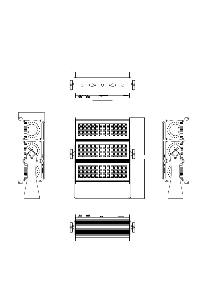
Dimensions
All dimensions are in millimeters
137
336
106
422
1.0
Page 3
WARNING!
Read the safety precautions in this section before
installing, powering, operating or servicing this
product
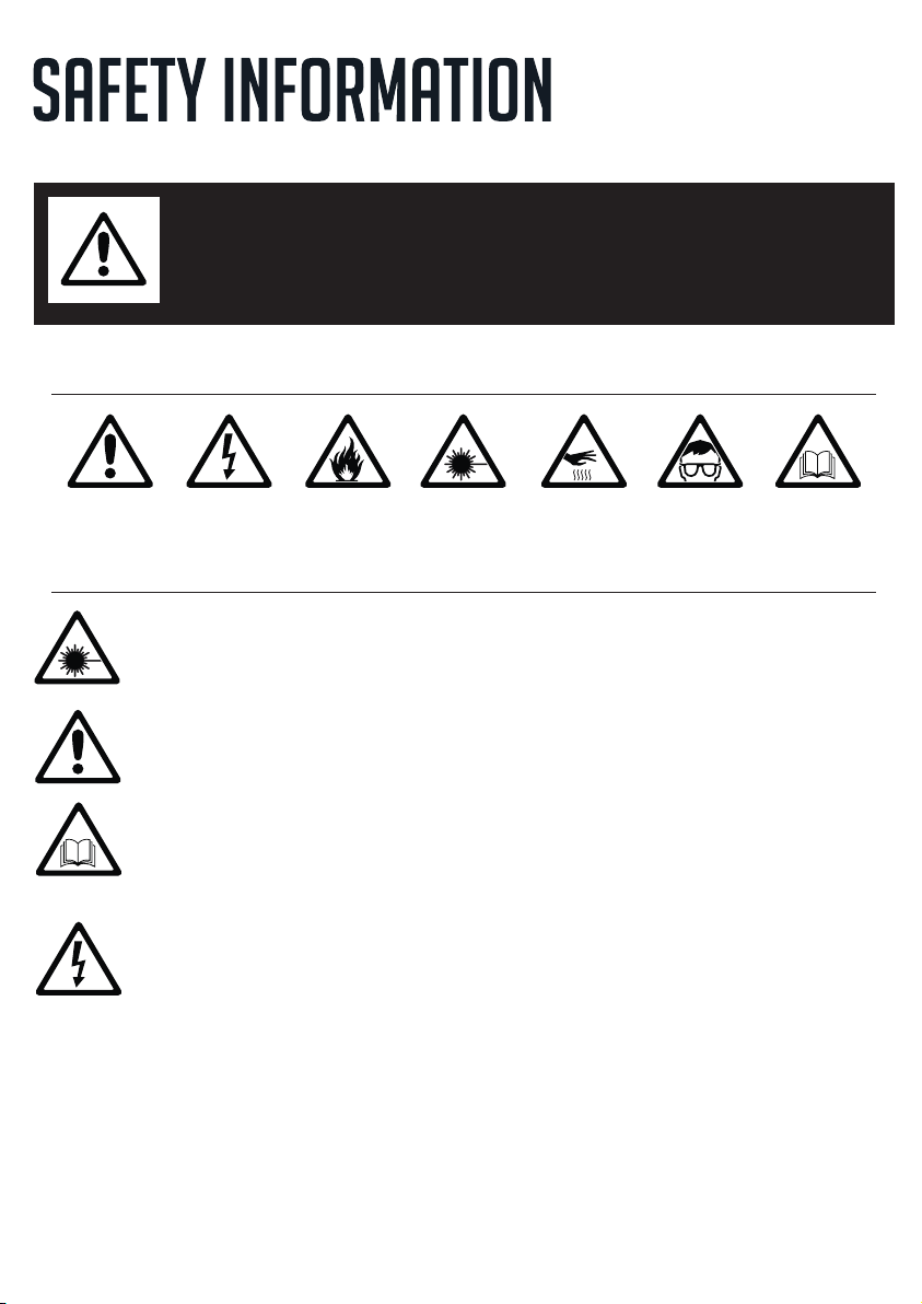
The fol lo wing sy mbols a re u sed to id entif y im porta nt safe ty inform ation o n the produ ct and in t his manua l:
DAN GER!
Saf ety haz ard.
Ris k of seve re
inj ury or de ath.
Warning! Risk Group 3 (high risk) LED product according to EN 62471. Do not look into the beam at a distance
of less than 3 meters from the front surface of the product. Do not view the light output with optical instruments
or any device that may concentrate the beam.
This product is for professional use only. It is not for household use.
This product presents risks of severe injury or death due to fire and burn hazards, electric shock and falls.
Read this manual before installing, powering or servicing the fixture, follow the safety precautions listed below and
observe all warnings in this manual and printed on the fixture. If you have questions about how to operate the fixture
safely, please contact your supplier.
PROTECTION FROM ELECTRIC SHOCK
l Disconnect the fixture from AC power before removing or installing any cover or part and when not in use.
l Always ground (earth) the fixture electrically.
l Use only a source of AC power that complies with local building and electrical codes and has both overload and
l Before using the fixture, check that all power distribution equipment and cables are in perfect condition and rated for
l Power input and through out cables must be rated 16A minimum, have three conductors 1.5 mm² minimum
l Use only cable connectors to connect to power input sockets. Use only cable PowerCON TR-1 PowerCON TR-1
l Isolate the fixture from power immediately if the power plug or any seal, cover, cable, or other component is
DAN GER!
Haz ardou s
vol tage. R isk of
let hal or se vere
ele ctric s hock.
WAR NIN G!
Fir e hazar d.
WAR NIN G!
LED l ight
emi ssion . Risk of
eye i njury.
WAR NIN G!
Bur n hazar d. Hot
sur face. D o not
tou ch.
WAR NIN G!
Wea r pro tec tiv e
eye wear.
WAR NIN G!
Ref er to use r
man ual.
ground-fault (earth-fault) protection.
the current requirements of all connected devices.
conductor size and an outer cable diameter of 5 - 15 mm . Cables must be hard usage type and heat-resistant to 90°
C minimum.
connectors to connect to power through sockets.
damaged, defective, deformed, wet or showing signs of overheating. Do not reapply power until repairs have been
completed.
2.0
Page 4
l Refer any service operation not described in this manual to a qualified technician.
l Socket outlets used to supply the fixture with power or external power switches must be located near the fixtures and
easily accessible so that the fixtures can easily be disconnected from power.
PROTECTION FROM BURNS AND FIRE
l The exterior of the fixture becomes hot during use. Avoid contact by persons and materials.
Allow the fixture to cool for at least 10 minutes before handling.
l Keep all combustible materials (e.g. fabric, wood, paper) at least 100 mm away from the fixture.
l Keep flammable materials well away from the fixture.
l Ensure that there is free and unobstructed airflow around the fixture.
l Do not illuminate surfaces within 200 mm of the fixture.
l Do not attempt to bypass thermostatic switches or fuses.
l If you relay power from one fixture to another using power through sockets, do not connect more than ten the fixture
in total to each other in an interconnected chain.
l Connect only other the fixture to fixture power throughput sockets. Do not connect any other type of device to these
sockets.
l Do not connect any other type of device to these sockets.
l Do not modify the fixture in any way not described in this manual.
l Do not use fixture on a dimmer.
PROTECTION FROM INJURY
l Do not look continuously at LEDs from a distance of less than 3 meters from the front surface of the fixture without
protective eyewear such as shade 4-5 welding goggles. At less than this distance, the LED emission can cause eye
injury or irritation. At distances of 3 meters and above, light output is harmless to the naked eye provided that the
eye’s natural aversion response is not overcome.
l Do not look at LEDs with magnifiers, telescopes, binoculars or similar optical instruments that may concentrate the
light output.
l Ensure that persons are not looking at the LEDs from within 3 meters when the product lights up suddenly. This can
happen when power is applied, when the product receives a DMX signal, or when SERVICE menu items are
selected.
l Fasten the fixture securely to a fixed surface or structure when in use.
l Ensure that any supporting structure and/or hardware used can hold at least 10 times the weight of all the devices
they support.
l Allow enough clearance around the fixture to ensure that it cannot collide with an object or another fixture when it
moves.
l Check that all external covers and rigging hardware are fastened securely.
l Block access below the work area and work from a stable platform whenever installing, servicing or moving the
fixture.
l Do not operate the fixture with missing or damaged covers, shields or any optical component.
3.0
Page 5
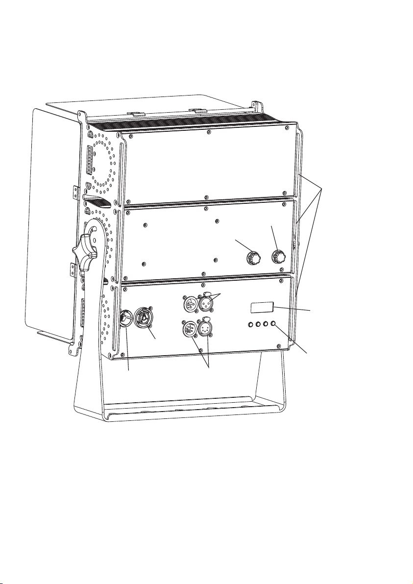
fixture overview
Manual dimmer control
3P DMX INput & OUTput
Safety cable
attachment point
Manual CCT control
LCD Display
AC mains power
through
AC mains power input
Control buttons
5P DMX INput & OUTput
4.0
Page 6
Using for the first time
Warning! Read “Sa fety Info rmation” on page 2 before installing, powering, operating or servicing the fixt ure.
Before applying power to the fixture:
l Check that the loca l AC mains powe r source is within the fixt ure’s powe r voltage and frequency ranges.
l See “Power cabl es and power plug” on page 6.
AC power
War ning! Read “Safet y Information” star ting on page 2 before connectin g the fixtures to AC mains powe r.
War ning! For protectio n from electric shock, the fixt ure must be grounded (earthed). The power
distributi oncircuit must be equip ped with a fuse or circuit bre aker and ground-fau lt (earth-fault ) protection.
War ning ! Sock et outlets or exter nal power swi tche s used to suppl y the fix ture with pow er must be
loc ated near the fixtu re and ea sily ac cessibl e so that th e fixt ures can easi ly be dis conn ected from power.
Impor tan t! Do n ot insert or r emo ve li ve conne cto rs to a pply or cut po wer, a s thi s may Power CON T R-1
cause a rci ng at t he term ina ls th at wi ll dama ge th e con nectors.
Impor tan t! Do n ot use an exte rna l dim ming sy ste m to su pply power t o the f ixt ure, as t his m ay ca use
damag e to th e fix ture that is n ot co ver ed by the p rod uct w arranty.
power voltage
War nin g! Ch eck tha t the v olt age ran ge sp eci fie d on the fi xtu res l abel ma tch es th e loc al AC mai ns po wer
volta ge be for e apply ing p owe r to th e fixtu re.
The fix tur es ac cepts AC m ain s pow er at 1 00-24 0 V nom ina l, 50/6 0 Hz. D o not a ppl y AC mains p owe r to th e
fixtu re at a ny ot her vol tag e tha n spe cifie d.
5.0
Page 7

power cables
Wire Color (EU models)
Wire Color (US models)
Conductor
Symbol
Brown
Black
LiveLBlue
White
Neutral
N
Yellow/Green
Green
Ground (earth)
or
Power i npu t and t hroug hpu t cab les m ust be ra ted 1 6A min imum, h ave t hre e conducto rs 1. 5 mm² m inimu m
condu cto r siz e and an ou ter c abl e dia meter o f 5 - 15 mm . Cab les mus t be ha rd us age t ype and h eat - res istan t
to 90°C m ini mum . In the EU t he ca ble m ust b e HAR app rov ed or e quiva len t.
If you in sta ll a po wer plu g on th e pow er ca ble, in sta ll a gr oundi ng- typ e (earthed ) plu g tha t is rate d 16A
minim um. F oll ow the pl ug ma nuf act urer’s ins truct ion s. Tabl e 1 sho ws standar d wir e col or-co din g sch emes
and som e pos sib le pin id ent ifi cat ion sch eme s; if p ins are n ot cl ear ly identif ied .
Table 1 : Wire color-coding and power connections
Relaying power to other devices
War nin g! Do n ot conn ect m ore t han thr ee fi xtu res i n total t o AC mai ns po wer in on e int erc onn ected c hai n.
Power c an be r ela yed to an oth er de vic e via the throu ghp ut so cket.Power CON T R-1
If you da isy c hai n the fix tur es in a c hai n so that t hey a ll dr aw AC main s pow er vi a the f irst fi xtu re, c ertai n
point s mus t be re spect ed:
• A he avy d uty, t hre e-c onduc tor, 1 .5 mm cabl e mus t be used t o con nec t the first fi xtu re to AC m ains po wer.
• connecto rs must be used to draw AC mains power from the fixtu res power throughpu t sockets Power CON T R-1
and connectors must be used to supp ly power at the fixture’s power input sockets.PowerCON TR-1
• No matt er wh at th e AC mains p owe r vol tag e is, do no t con nec t more th an th ree t he fi xture i n tot al ( in cludi ng
the fir st fi xtu re) to AC ma ins p owe r in on e inter con nec ted dai sy ch ain u sin g power i npu t and t hroug h out
conne cto rs.
2
DATA LINK
A DMX 512 da ta li nk is r equir ed in o rde r to co ntrol a f ixt ure v ia DMX. Th e fixtu re ha s 3 & 5-p in XLR co nne cto rs
for DMX d ata i npu t and out put . The p in- out o n conne cto rs is p in 1 = sh ield, p in 2 = co ld (- ), and pi n 3 = hot ( +)
Pins 4 an d 5 in th e 5-p in XLR co nne cto rs ar e not use d.
tips for reliable data transmission
To connec t the f ixt ure to da ta:
1. Conne ct the DM X data ou tput from the co ntrolle r to the 3 or 5 -pi n XLR c onnec tor o f the n ear est fix tur e.
2. Conn ect t he DM X outpu t of th e fix tur e close st to t he co ntrol ler t o the D MX in put of th e nex t fix ture an d
conti nue c onn ectin g fix tur es ou tput to i npu t.
6.0
Page 8

Physical installation
War nin g! Th e fix ture mu st be e ith er fa stene d to a fl at su rface s uch a s a sta ge or w all, or c lam ped t o a truss o r
simil ar st ruc ture in a ny or ien tat ion usi ng a ri ggi ng clam p.
War nin g! If t he fixt ure c an ca use inj ury o r dam age i t if fall s, at tac h an appr ove d saf ety c able to o ne of t he
safet y cab le at tachm ent p oin ts on t he base ( see “ Fix ture ov erv iew ” on pa ge 4).
Check t hat a ll su rface s to be i llu min ated ar e min imu m 200 mm. f rom t he fi xtu re, tha t com bus tible m ate ria ls
(wood , fab ric , paper, e tc. ) are m ini mum 100 m m. fr om th e fixtu re, t hat t her e is free a irf low a round t he fi xtu re
and tha t the re ar e no flam mab le ma ter ials ne arb y.
Fastening the fixture to a flat surface
The fix tur e can b e faste ned t o a fix ed fl at surf ace t hat i s orien ted a t any a ngl e. Chec k tha t the s urfac e can
suppo rt at l eas t 10 time s the w eig ht of a ll fixt ure s and e quipm ent t o be in sta lled on i t.
War nin g! Th e sup porti ng su rfa ce mu st be har d and f lat o r air ven ts in t he ba se ma y be bloc ked , whi ch will
cause o ver hea ting. F ast en th e fix ture se cur ely. D o not s tan d it on a sur fac e or le ave it wh ere i t can b e mov ed
or can fa ll ov er. Att ach a sec ure ly an cho red saf ety c abl e to the sa fet y cab le at tachm ent p oin t (see “F ixt ure
overv iew ” on pa ge 4) if th e fix tur e is to b e insta lle d in an y locat ion w her e it ma y fall an d cau se in jury or
damag e if th e pri mary at tac hme nt fa ils.
1. Bloc k acc ess u nder th e wor k are a. Wo rki ng from a s tab le pl atf orm, ha ng th e fix ture on t he tr uss . Tigh ten
the rig gin g cla mp.
2. Secu re th e fix ture ag ain st cl amp f ailur e wit h a sec ondar y att ach men t such as a n app rov ed safe ty ca ble
that is r ate d for t he weig ht of t he fi xtu re usin g one o f the a ttach men t poi nts a t the edg es of t he ho using ( see
“Fixt ure o ver view” o n pag e 4). D o not u se any ot her p art o f the fix tur e as a sa fet y cable a tta chm ent poi nt.
7.0
Page 9

SETUP
War nin g! Re ad “Saf ety I nfo rmati on” o n pag e 2 bef ore ins tal lin g, powe rin g, op erating th e fix tur e.
Control panel and menu navigation
The onb oar d con trol pa nel a nd ba ckl it grap hic d isp lay are u sed t o set t he fixture ’s DM X add res s, configu re
indiv idu al fi xture s ett ing s (pe rsona lit y), r ead out d ata a nd ex ecu te serv ice u til ities . See “ Onb oard contr ol
menus ” on for a com ple te li st of men us an d com man ds. page 9
Using t he co ntr ol butt ons
• To ente r the men u sel ect [ MOD E].
• Press [ UP] a nd [D OWN] to scro ll wi thi n a menu or a dju st va lues.
• To ente r a menu, s ele ct a fu nct ion or ap ply a s ele ction , pre ss [E NTE R].
• To esca pe a func tio n or mo ve ba ck one le vel i n the m enu str uct ure , pre ss [MOD E].
DMX address setting
The DMX address, also known as the start channel, is the first channel used to receive instructions from the controller.
For ind epe nde nt cont rol , eac h fix ture mu st be a ssi gned it s to a se par ate c hanne l .
The DMX a ddr ess c an be con fig ure d by us ing the D MX ADD RES S menu in t he co ntr ol panel. Fo r set tin g the
DMX add res s pre ss [ENT ER] b efo re yo u can cha nge t he ad dress .
• The m ain scr een w ill s how a ' dot' an d the b ack light w ill b e swi tched off when a DM X sig nal i s detec ted .
• The f ixtur e is fu lly R DM re ady. So when yo u are u sin g a RDM r eady co nso le yo u can add res s the u nit and
read ou t its c omp lete st atu s. Fo r RDM f uncti ons p lea se refe r to th e ANSI /ES TA E1.2 0-200 6 sta nda rd
8.0
Page 10
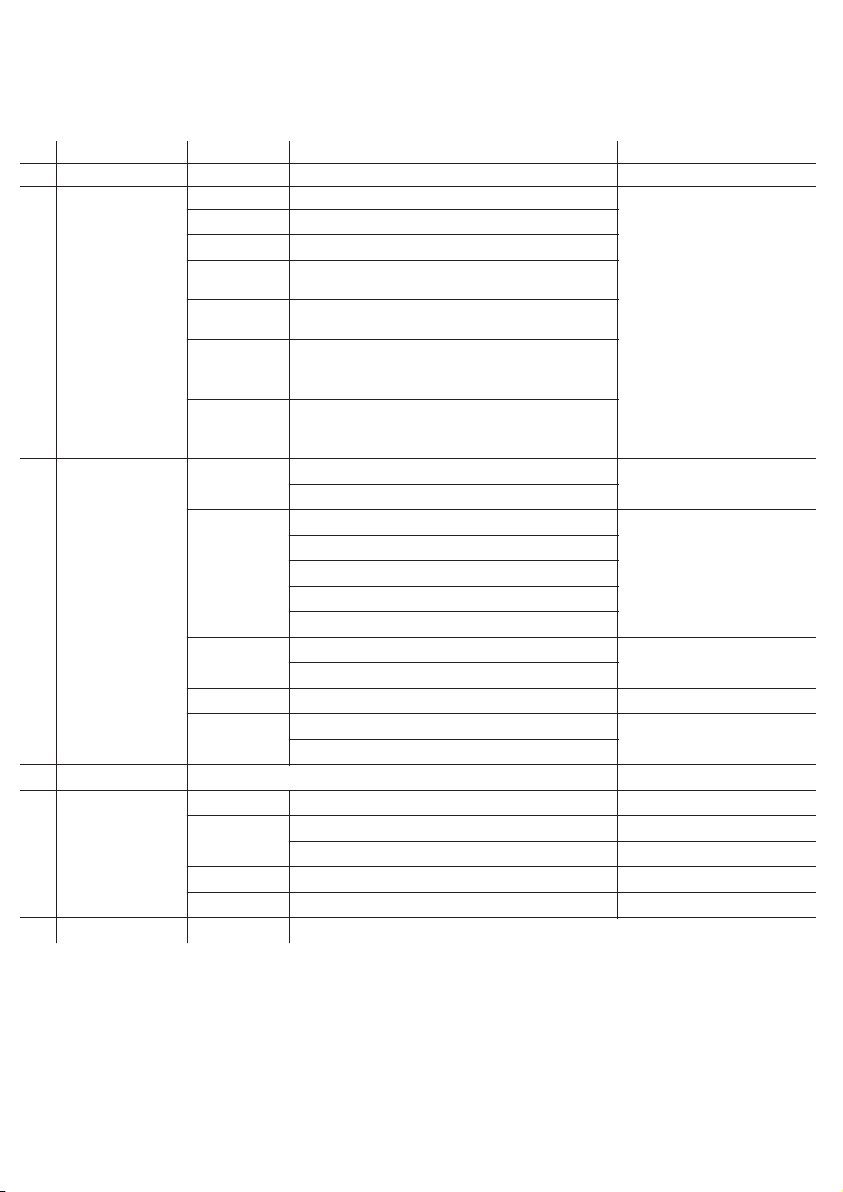
Onboard control menus
NO.
Main Menu
Menu level 2
Menu level 3
Remark
1
DMX
001-512
Default 001
2
MODE
2CH
1.Coo l whi te, 2 .warm w hit e
Default : 5CH
3CH
1.Dimmer, 2.Cool white, 3.warm white
4CH
1.Dimmer, 2.Cool white, 3.warm white, 4.CCT
5CH
1.Dim mer, 2 .Co ol whit e, 3. war m whi te, 4.C CT,
5.Str obe
6CH
1.Dimmer, 2.Cool white, 3.warm white, 4.CCT,
5.Strobe. 6,Dimmer speed
8CH
1.Dimmer, 2.B1 Cool white, 3.B1 warm white, 4.B2
Cool white, 5.B2 warm white, 6.B2 Cool white, 7.B2
warm white, 8.CCT
10CH
1.Dimmer, 2.B1 Cool white, 3.B1 warm white, 4.B2
Cool white, 5.B2 warm white, 6.B2 Cool white, 7.B2
warm white, 8.CCT, 9.Strobe. 10,Dimmer speed
3
SET
D.spe ed
Off
Default : Off
Speed 1 / S pee d 2 / Spe ed 3 / Spee d 4
D.cur ve
linea r
Default : linear
Squar e (Sq uar e law)
INV Sq (I NV Sq uar e law)
S-Cur ve
Speci al
KEYLO CK
ON
Password:MENU, UP, DOWN,
MENU, UP, DOWN,ENTER
OFF
REFRE SH
600 / 120 0 / 240 0 / 480 0 Hz
Default : 600 Hz
MASTE R
Maste r
Default : Slave
Slave4CCT
2800K ,32 00K ,3500 K,3 800 K,4 200K, 450 0K, 4800K ,50 00K ,56 00K
Default : 2800K
5
INFO
VERSI ON
VX.XX
USAGE .T
Xxxx H
RESET
Use tim e res et (p asswo rd)
TEMP
XXX℃
RDM.U ID
xxxxx xxx xxx xx
6
FACTORY
LOAD
Pleas e reb oot p ower be for e res et ta kes effect !
9.0
Page 11

50
6
0
0
4
0
3
0
2
0
1
0
7
0
8
0
9
0
1
0
0
4.2 K
5
K
.8
2
.6K
Rotat e the m anu al dimm er co ntr ol kn ob to cha nge t he br ightn ess f rom 0 - 100 %.
Rotat e the m anu al CCT con trol kn ob to c han ge the co lor t emp era ture fr om 28 00K t o 5600K w hit e.
Sign al priority a fter boot:
1. DMX mo de:
If the EL 45 1.T W detec t an DM X sig nal, it will b e con tro lled by t his s ign al.
2. Mast er/ Sla ve
The mas ter i s con troll ed by t he di mme r switc h + CCT s wit ch an d con trols a ll co nne cted sl ave s. To cha nge a s lav e to
maste r use t he on board c ont rol m enu ( Set/M ast er/ Maste r) or t urn t he di mmer sw itc h to 0% , pause 1 s ec, t urn i t to
100% an d pau se 1 se c. Th is fu nctio n wil l be di sable d 60 se c. af ter b oot.
3. Stan d alo ne / No s ignal
The lam p is co ntr olled b y the p osi tio n of the ma nua l dim mer and C CT contr ol.
Troubl esh oot ing:
If ther e are m ore t han one m ast er in t he li ne, tha n it is p oss ible to f orc e the o the r maste rs to c han ge remo tel y to
slave s. Th is co uld b e don e by turn ing t he di mmer of t he se lec ted m aster t o 0%, w ait 1 sec, tu rn it t o 100 % and w ait
again 1 sec . The n all o the r maste rs sw itc h remot ely t o sla ves .This f unc tio n will be d isa ble d 60 sec. afte r boo t.
10.0
Page 12
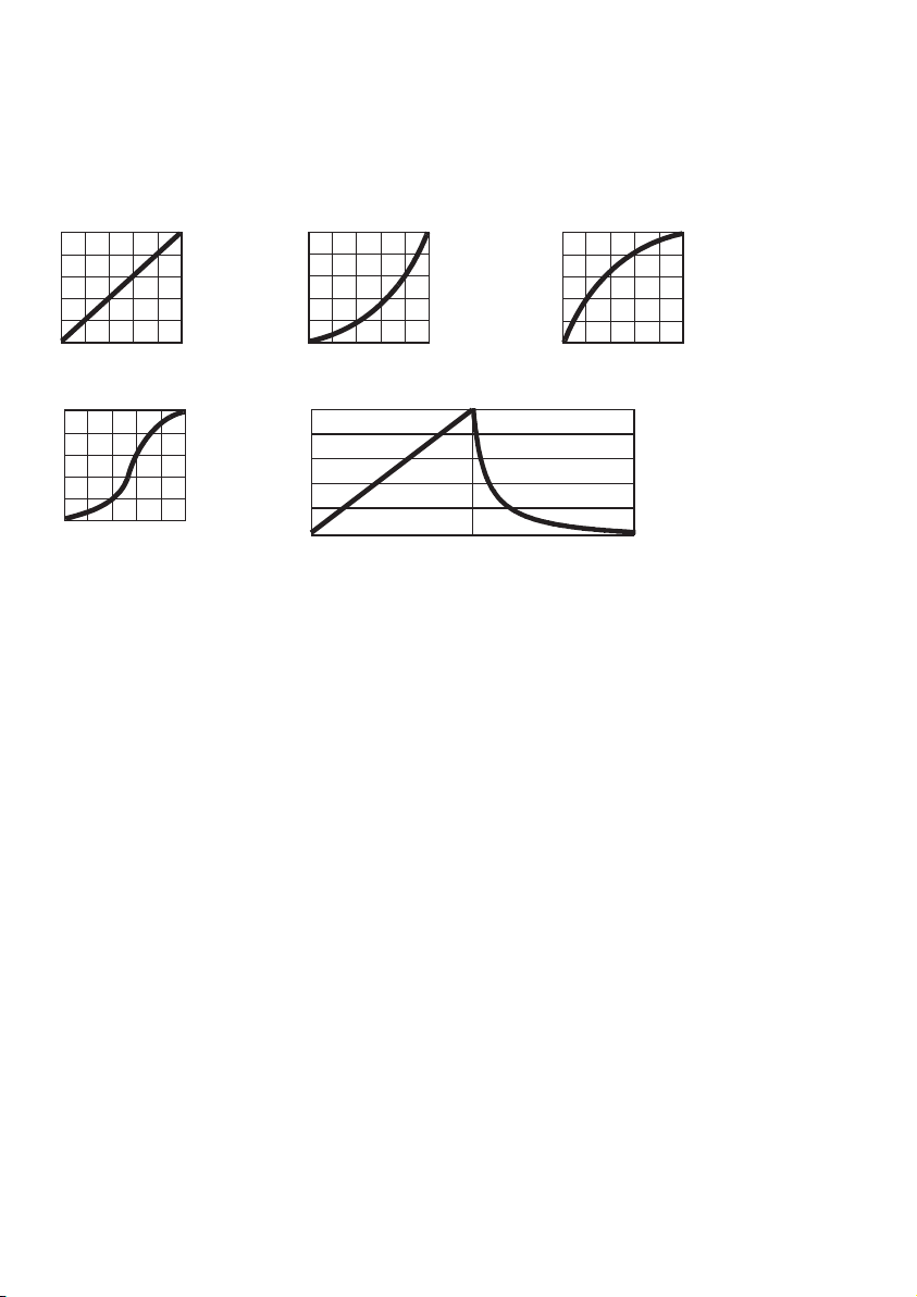
DIMMER MODE
provides five dimming options (see picture below):
Outpu t
DMX %
LINEA R
Outpu t
DMX %
S-CURVE
l LINEAR – the increase in light intensity appears to be linear as DMX value is increased.
l SQUARE LAW – light intensity control is finer at low levels and coarser at high levels.
l INV Square law – light intensity control is coarser at low levels and finer at high levels.
l S-CURVE – light intensity control is finer at low levels and high levels and coarser at medium levels.
l Special – the light intensity was linear increase with DMX value , and light intensity control is finer at low level
with DMX values decrease , the dimmer speed will also has effect on it
Whichever DIMMER CURVE option you select, you can choose between Off or Speed 1 / 2 / 3 / 4 dimming settings:
l Off is the default setting. It gives a virtually instantaneous reaction when you dim from one intensity to another,
but dimming slowly from one intensity to another may appear slightly uneven.
l The Speed 1 / 2 / 3 / 4 setting gives smoother dimming during slow changes in intensity, but it limits the speed of
dimming changes slightly. This makes it ideal for slow, smooth dimming, but a short time-lag may be noticeable
if you try to dim quickly from one intensity to another.
Outpu t
DMX %
SQUAR E LAW
Outpu t
DMX % Up DM X % Dow n
SPECI AL
Outpu t
DMX %
INVER SE SQ UAR E LAW
11.0
Page 13

dmx protocols
2CH
Function
Value
Setting
Remark
1
Cool white
000 - 255
0 - 100%
2
Warm white
000 - 255
0 - 100%
3 CH
Function
Value
Setting
Remark
1
Dimmer
000 - 255
0 - 100%
2
Cool white
000 - 255
0 - 100%
3
Warm white
000 - 255
0 - 100%
4 CH
Function
Value
Setting
Remark
1
Dimmer
000 - 255
0 - 100%
2
Cool white
000 - 255
0 - 100%
3
Warm white
000 - 255
0 - 100%
4
CCT
000 - 255
2800k - 5600k
5 CH
Function
Value
Setting
Remark
1
Dimmer
000 - 255
0 - 100%
2
Cool white
000 - 255
0 - 100%
3
Warm white
000 - 255
0 - 100%
4
CCT
000 - 255
2800k - 5600k
5
Strob e
000 - 024
025 - 064
065 - 069
070 - 084
085 - 089
090 - 104
105 - 109
110 - 12 4
125 - 129
130 - 144
145 - 149
150 - 164
165 - 169
170 - 184
185 - 189
190 - 204
205 - 209
210 - 224
225 - 229
230 - 244
245 - 255
ON
Strob e 1 (fa st → sl ow)
ON
Strob e 2: op eni ng puls e (fa st → sl ow)
ON
Strob e 3: cl osi ng puls e (fa st → sl ow)
ON
Strob e 4: ra ndo m strob e (fa st → sl ow)
ON
Strob e 5: ra ndo m openi ng pu lse ( fas t → slow)
ON
Strob e 6:r and om clos ing p uls e (fa st → slow )
ON
Strob e 7: bu rst p ulse (f ast → s low )
ON
Strob e 8: ra ndo m burst p uls e (fa st → sl ow)
ON
Strob e 9:s ine w ave (fa st → sl ow)
ON
Strob e 10: b urs t (fast → slow )
ON
2 cha nnels:
3 cha nnels:
4 cha nnels:
5 cha nnels:
12.0
Page 14
dmx protocols
6 CH
Function
Value
Setting
Remark
1
Dimmer
000 - 255
0 - 100%
2
Cool white
000 - 255
0 - 100%
3
Warm white
000 - 255
0 - 100%
4
CCT
000 - 255
2800k - 5600k
5
Strob e
000 - 255
ON
Strob e 1 (fa st → sl ow)
ON
Strob e 2: op eni ng puls e (fa st → sl ow)
ON
Strob e 3: cl osi ng puls e (fa st → sl ow)
ON
Strob e 4: ra ndo m strob e (fa st → sl ow)
ON
Strob e 5: ra ndo m openi ng pu lse ( fas t → slow)
ON
Strob e 6:r and om clos ing p uls e (fa st → slow )
ON
Strob e 7: bu rst p ulse (f ast → s low )
ON
Strob e 8: ra ndo m burst p uls e (fa st → sl ow)
ON
Strob e 9:s ine w ave (fa st → sl ow)
ON
Strob e 10: b urs t (fast → slow )
ON
6
Fade
000 - 255
dimme r spe ed (f ast → slo w)
8 CH
Function
Value
Setting
Remark
1
Dimmer
000 - 255
0 - 100%
2
B1 Cool white
000 - 255
0 - 100%
3
B1 Warm white
000 - 255
0 - 100%
4
B2 Cool white
000 - 255
0 - 100%
5
B2 Warm white
000 - 255
0 - 100%
6
B3 Cool white
000 - 255
0 - 100%
7
B3 Warm white
000 - 255
0 - 100%
8
CCT
000 - 255
2800k - 5600k
6 cha nnels:
8 cha nnels:
13.0
Page 15

dmx protocols
10 CH
Function
Value
Setting
Remark
1
Dimmer
000 - 255
0 - 100%
2
B1 Cool white
000 - 255
0 - 100%
3
B1 Warm white
000 - 255
0 - 100%
4
B2 Cool white
000 - 255
0 - 100%
5
B2 Warm white
000 - 255
0 - 100%
6
B3 Cool white
000 - 255
0 - 100%
7
B3 Warm white
000 - 255
0 - 100%
8
CCT
000 - 255
2800k - 5600k
9
Strob e
000 - 255
ON
Strob e 1 (fa st → sl ow)
ON
Strob e 2: op eni ng puls e (fa st → sl ow)
ON
Strob e 3: cl osi ng puls e (fa st → sl ow)
ON
Strob e 4: ra ndo m strob e (fa st → sl ow)
ON
Strob e 5: ra ndo m openi ng pu lse ( fas t → slow)
ON
Strob e 6:r and om clos ing p uls e (fa st → slow )
ON
Strob e 7: bu rst p ulse (f ast → s low )
ON
Strob e 8: ra ndo m burst p uls e (fa st → sl ow)
ON
Strob e 9:s ine w ave (fa st → sl ow)
ON
Strob e 10: b urs t (fast → slow )
ON
10
Fade
000 - 255
dimme r spe ed (f ast → slo w)
10 ch annel s:
14.0
Page 16

Specifications
Physical
Length
336mm
Width
137mm
Height
422mm
Weight
8.55 kg
Optics
Light source
972 SMD 5050
beam angle
120°
Control and Programming
Control
DMX512-A
DMX channels
2 / 3 / 4 / 5 / 6 / 8 / 10
Setting and addressing
Control panel with backlit LCD graphic display
Protocol
RDM, USITT DMX512-A
CONSTRUCTION
Color
Black
Housing
metal
Protection rating
IP 20
Installation
Orientation
Any
Minimum distance to combustible materials
100 mm. from fixture
Minimum distance to illuminated surfaces
200 mm. from fixture
Connections
AC power input
PowerCON TR-1 input socket
AC power throughput
PowerCON TR-1 output socket
DMX data in/out
3 & 5 pin locking XLR
Electrical
AC power
100-240 V nominal, 50/60 Hz
Maximum total power consumption
100V:520 W, 5.24A, PF:0.995.
240V:488 W, 2.12A, PF:0.968
Power supply unit
Auto-ranging electronic switch mode
Power consumption, zero light output
<18 W
Cooling
active
15.0
 Loading...