

XONTEL XT-18AP User Manual
User Manual
XT-18AP-Dual band 1200Mbps Ceiling AP
POE
This is the user manual of XT-18AP, Dual band 2.4G &5.8G, 1200Mbps Ceiling AP, which
will approximate guide you how to set and apply the Ceiling AP, it provide a convenient
graphical interface for network construction and maintenance person, as well as a user
through a simple and accurate operation, and configuration management of the ceiling
wireless access point.
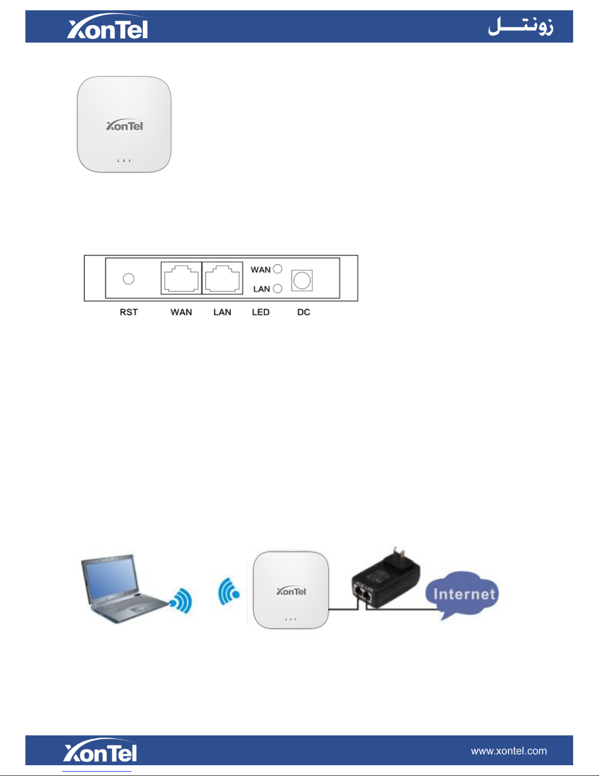
1st Hardware and Operation mode Instruction
LED indicator:
Green: Power Indicator
Blue: W iFi Indicator
AP Interface:
RST: Reset Button, it make AP revert to default data after press it 15 seconds.
WAN: Gigabit WAN Port, connect with ADSL modem or Internet mainly. It will be LAN port under Wireless AP and WiFi
Repeater operation mode
LAN: Gigabit LAN Port to end users
LED: LED Indicator of WAN port and LAN port
DC: DC power connector
Power Supply:
1. PoE Adapter Power Supply:
The connection diagram showed as P1, internet cable connect to PoE adapter’s LAN Port, Ceiling AP’s WAN port
connect to PoE adapter’s PoE Port, then PC will access into ceiling AP through cable or wireless
Pls note, if the PD Wireless AP support 24V passive PoE, then the PoE adapter should be 24V Passive PoE,.
If the PD wireless AP support 48V IEEE 802.3af standard PoE, the PoE adapter should be 48V PoE standard.
P1
2. Powered by PoE Switch
The connection diagram shows as P2, Internet cable from PoE Switch to Ceiling AP’s WAN Port, then PC access into

ceiling AP wired/wireless.
Pls note, if the PD Wireless AP support 24V passive PoE, then the PoE switch should be 24V Passive PoE,.
If the PD wireless AP support 48V IEEE 802.3af standard PoE, m the PoE switch should comply with 802.3af 48V PoE
standard.
P2
Operation Mode:
There are three operation mode on this wireless AP:
P3 Operation Mode
Connect Wireless AP with PC:
Use can connect the PC with wireless AP by Wireless SSID and LAN cable:
The diagram of wireless connection showed as follow:
Pls note: the default SSID is WirelessAP2.4G/5.8G, S SI D ’s p a s sw or d is 6 6 66 66 6 6
The diagram of LAN cable connection showed as follow:
2nd: Login
1)Connect the Ceiling AP with computer
2)Configure the PC’s local connection IP address as 192.168.188.X (X is number from 2 to 254), subnet mask is
255.255.255.0, follow P4 and P5 to finish.
P4 Setting of computer’s IP address
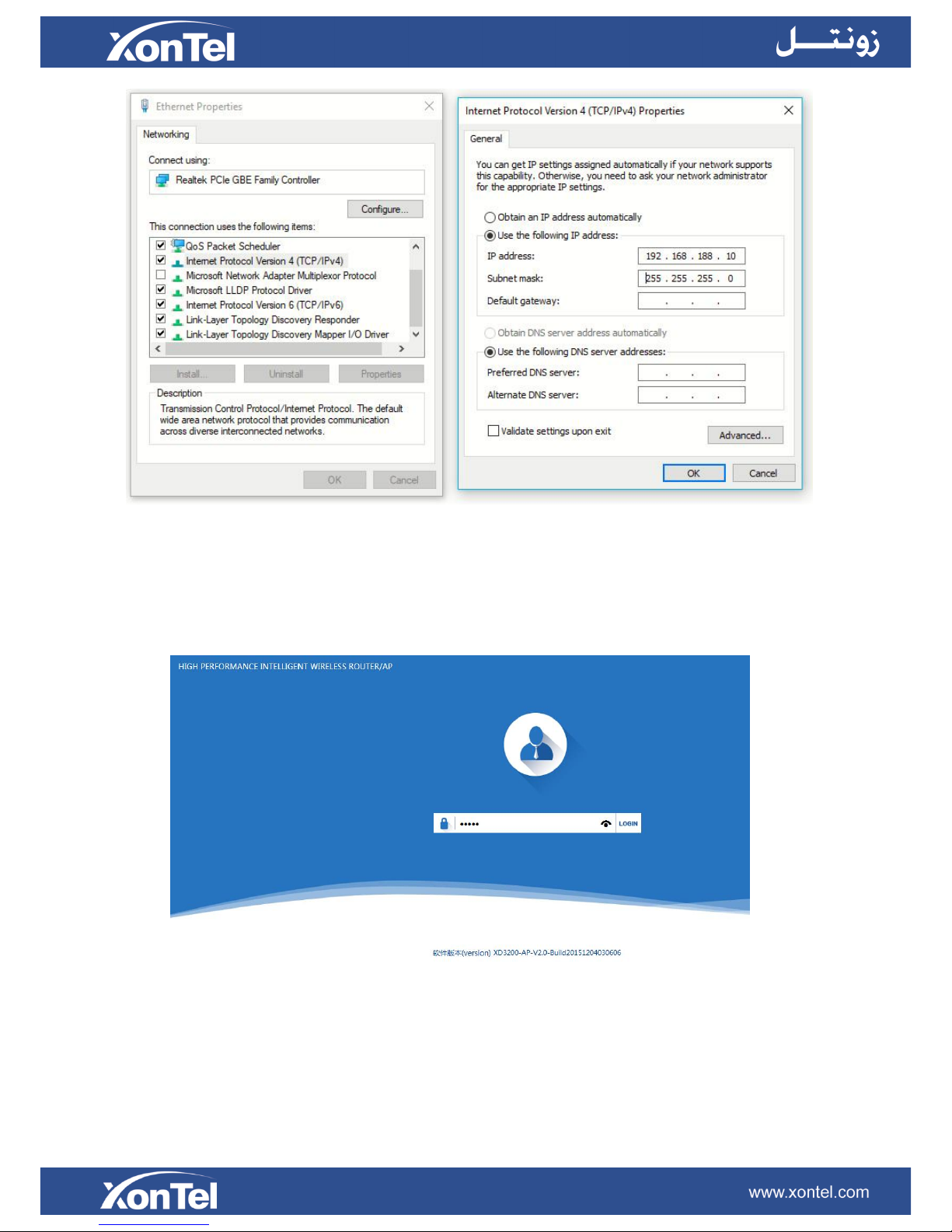
P 5 Setting of computer’s IP address
3) Input 192.168.188.253 into IE browser, then pop up the login page, the default login user name: Admin,
Passwords: admin, pls do following P6
P6 Login
3rd: WEB GUI interface Setting:
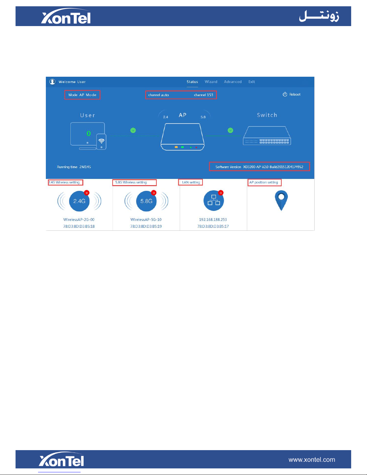
1) Status
After login, then P7 Device Status will be showed:
P7: Device Status
In this ceiling wireless AP, the default operation mode is AP mode.
Then in 2.4G Wireless Setting, GUI configuration page showed as below:
User can configure the SSID, password, band width, channel here, then Apply to finish.
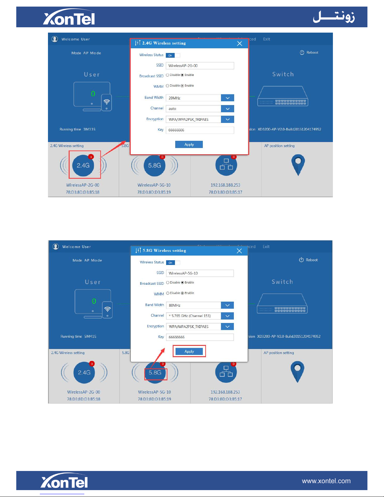
P8. 2.4G Wireless setting
5.8G Wireless Setting GUI configuration setting showed as P8:
P9 5.8G Wireless Setting
LAN Setting to configure the DHCP or Fix IP
 Loading...