

XONTEL S2400 User Manual

S2400 User Manual
Copyright
Copyright 2016 SAHAB Technology Co.. All rights reserved.
No parts of this publication may be reproduced or transmitted in any form or by any
means, electronic or mechanical, photocopying, recording, or otherwise, for any
purpose, without the express written permission of SAHAB Technology Co.. Under
the law, reproducing includes translating into another language or format.
Declaration of Conformity
Hereby, SAHAB Technology Co..declares that XonTel
S2400 is in conformity with the essential requirements and
other relevant provisions of the CE, FCC.
Warranty
The information in this document is subject to change without notice.
SAHAB Technology Co..makes no warranty of any kind with regard to this guide,
including, but not limited to, the implied warranties of merchantability and fitness for a
particular purpose. SAHAB Technology Co..shall not be liable for errors contained
herein nor for incidental or consequential damages in connection with the furnishing,
performance or use of this guide.
WEEE Warning
In accordance with the requirements of council directive 2002/96/EC on
Waste of Electrical and Electronic Equipment (WEEE), ensure that at endof-life you separate this product from other waste and scrap and deliver to
the WEEE collection system in your country for recycling.

S2400 User Manual
Contents
S2400 Overview ........................................................................................................ 1
Introduction ......................................................................................................................... 1
Feature Highlights ............................................................................................................... 1
S2400 Front Panel .................................................................................................................... 2
S2400 Rear Panel .............................................................................................................. 3
Installation ................................................................................................................ 4
S2400 Packing List ................................................................................................................... 4
Specifications and Operating Environment ......................................................................... 4
Placement Instructions ........................................................................................................ 5
Connect Your S2400 ........................................................................................................... 5
Connection of Ethernet Ports .......................................................................................... 5
Connection of FXO Ports ................................................................................................ 5
Power Connection ........................................................................................................... 5
Application Overview .............................................................................................. 7
Getting Started ......................................................................................................... 8
Accessing Web GUI ................................................................................................................. 8
Web Configuration Panel ......................................................................................................... 9
User Management .............................................................................................................. 9
Making and Receiving Calls .............................................................................................. 11
System Settings ..................................................................................................... 12
Network Settings ............................................................................................................... 12
Security Center ................................................................................................................. 13
Security Center ............................................................................................................. 13
Firewall Rules ................................................................................................................ 14
IP Blacklist ..................................................................................................................... 16
AMI Settings .................................................................................................................. 17
Alert Settings ................................................................................................................. 18
Password Settings ............................................................................................................ 19
Date and Time .................................................................................................................. 20
Extensions .............................................................................................................. 21
FXS Extensions ................................................................................................................ 21
VoIP Extensions ................................................................................................................ 27
Trunks .......................................................................................................................... 33
CO Lines ........................................................................................................................... 33
VoIP Trunks ....................................................................................................................... 37
Call Control ............................................................................................................. 41

S2400 User Manual
Outgoing Rules ................................................................................................................. 41
Outbound Route ............................................................................................................ 41
Seize a Line .................................................................................................................. 43
Incoming Rules ................................................................................................................. 44
PIN Settings ...................................................................................................................... 46
Blacklist ............................................................................................................................. 47
IVR ........................................................................................................................... 48
Ring Group ............................................................................................................. 50
Queue ...................................................................................................................... 52
Conference ............................................................................................................. 56
Configure a Conference Room ......................................................................................... 56
Join a Conference Room .................................................................................................. 56
Manage the Conference ................................................................................................... 57
Managing Voice on S2400 ..................................................................................... 58
System Prompt ................................................................................................................. 58
Custom Prompt ................................................................................................................. 61
Music on Hold ................................................................................................................... 62
Voicemail ........................................................................................................................... 64
Voicemail Settings ............................................................................................................ 64
Voicemail to Email ............................................................................................................. 65
How to Check Voicemail? ................................................................................................. 66
How to Change Voicemail Greetings? .............................................................................. 67
Business Calling Features .................................................................................... 69
Feature Code .................................................................................................................... 69
Call Transfer ..................................................................................................................... 71
Blind Transfer ................................................................................................................ 71
Attended Transfer.......................................................................................................... 71
Call Pickup ........................................................................................................................ 71
Group Call Pickup ......................................................................................................... 72
Direct Call Pick .............................................................................................................. 72
Intercom ............................................................................................................................ 73
Spy .......................................................................................................................................... 73
Call Parking ...................................................................................................................... 74
Speed Dialing .................................................................................................................... 74
Auto Recording ...................................................................................................... 76
Auto Recording Settings ................................................................................................... 76
SD Card Management ...................................................................................................... 77
Store Recordings to Network Disk ..................................................................................... 77
Share Recordings ............................................................................................................. 79
PBX Basic Settings ................................................................................................ 82
General Preferences ......................................................................................................... 82

S2400 User Manual
Business Hours ................................................................................................................. 83
Business Days .............................................................................................................. 84
Holidays ........................................................................................................................ 85
SIP Settings ............................................................................................................ 87
General ............................................................................................................................. 87
NAT ......................................................................................................................................... 87
Codecs .............................................................................................................................. 88
Status and Call Reports ................................................................................................. 89
Extension Status ............................................................................................................... 89
Trunk Status ................................................................................................................................. 90
Network Status ............................................................................................................................. 91
System Info ....................................................................................................................... 91
Call Logs ........................................................................................................................... 92
Record Logs ...................................................................................................................... 92
System Maintenance ............................................................................................. 94
Firmware Upgrade ............................................................................................................ 94
Automatic Updates ........................................................................................................ 94
Upgrade through HTTP ...................................................................................................... 95
Upgrade through TFTP ........................................................................................................... 96
Backup and Restore ......................................................................................................... 97
Reset and Reboot ............................................................................................................. 97
System Logs ..................................................................................................................... 98
Packet Tool .......................................................................................................................................... 99

S2400 User Manual
S2400 Overview
This chapter provides the following sections:
□
Introduction
□
Feature Highlights
□
S2400 Front Panel
□
S2400 Rear Panel
Introduction
XonTel S2400 is a fully-fledged PBX that delivers advanced communications features
of a large system to small office. XonTel S2400 maximizes cost-effectiveness with 8
CO lines, 24 analog extensions, 8 SIP extensions, 4 SIP trunks, and the ability to
handle calls with your mobile phone. It provides all the features you need in a plugand-play box, perfectly future proofing your telecom investment.
Feature Highlights
□
Hybrid System
Pre-configured with 8 CO lines, 24 analog extensions, 8 SIP extensions, and 4
SIP trunks.
□
Small Size, Large Capacity
Small size (440*250*44 mm), 1GHz ARM A8 application processor, large
memory (256MB DDR RAM, 256NAND Flash), external SD card, and high
performance C64X DSP for perfect voice quality.
□
Plug and Play
Ready to play out of the box with plug-and-play facility.
□
User-friendly Configuration
Manage the system via user-friendly Web interface without complicate
operations.
□
Personalize Your Extension in Your Way
Various features for extensions: distinctive ring tone, wake-up call, busy camp-on,
voicemail, and user accounts to log in S2400 Web GUI, etc.
□
Embedded Recording Capability
Record calls to monitor the conversation for various purposes required by your
business.
□
Advanced Call Handling
Flexible call routing, effective call queuing and distribution handle incoming calls
automatically.
S2400 User Manual
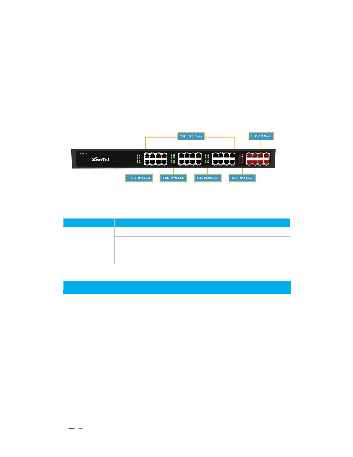
LED
LED Status Description
FXS Ports Status
Solid Green
The port is idle.
Blinking Green
There is an ongoing call on the port.
CO Ports Status
Solid Red
The port is being used.
Blinking Red
The port is idle.
Port
Description
FXS Ports (1-24)
For connection of analog phones/fax machines.
Co Ports (1-8)
For connection of CO lines.
□
Work Anytime Anywhere
Connect to the office telephone system with Linkus Mobile Client and stay
connected. Work on the move anytime, anywhere!
□
Cloud Service
Detect the new firmware from cloud server and upgrade automatically.
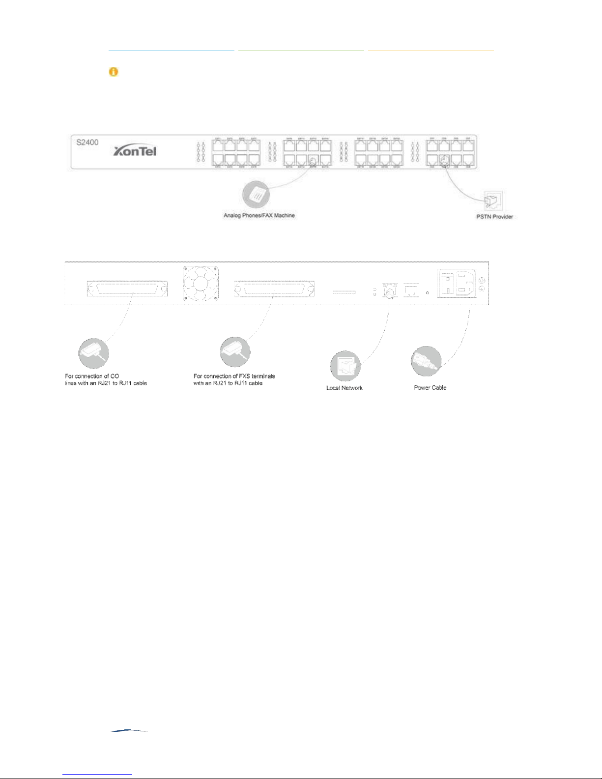
S2400 Front Panel
Figure 1-1 S2400 Front Panel
Table 1-1 S2400 Front Panel - LED Description
Table 1-2 S2400 Front Panels–Port Description
S2400 User Manual
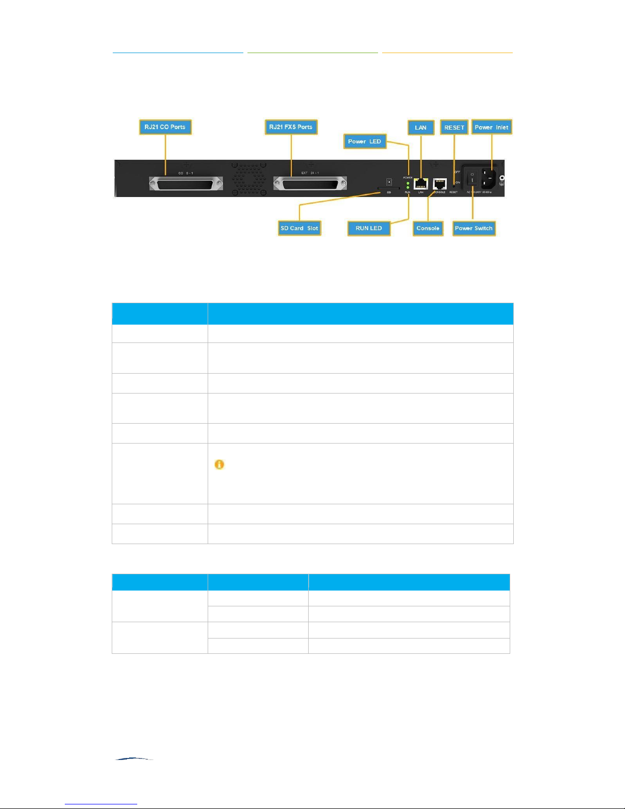
Port
Description
RJ21 CO Ports
For connection of CO lines with an RJ21 to RJ11 cable.
RJ21 FXS Ports
For connection of analog phones/fax machines with an RJ21 to
RJ11 cable.
SD Card Slot
Insert the SD card and restore the recording files.
LAN Port
10/100 Base-TX, connect one end of an RJ-45 Ethernet cable
into the LAN port.
Console Port
Used for service and maintenance.
Reset Button
Press the reset button to restore the factory defaults.
Please make sure that you want to reset, because once
reset the previous configurations would be
erased
automatically.
Power Switch
Power Inlet
For connection of power supply.
LED
LED Status Description
POWER
On The power is switched on.
Off The power is switched off.
RUN
Blinking
S2400 is running properly.
Not Blinking/Off
S2400 goes wrong.
S2400 Rear Panel
Figure 1-2 S2400 Rear Panel
Table 1-3 S2400 Rear Panels–Port Description
Table 1-4 S2400 Rear Panel–LED Description
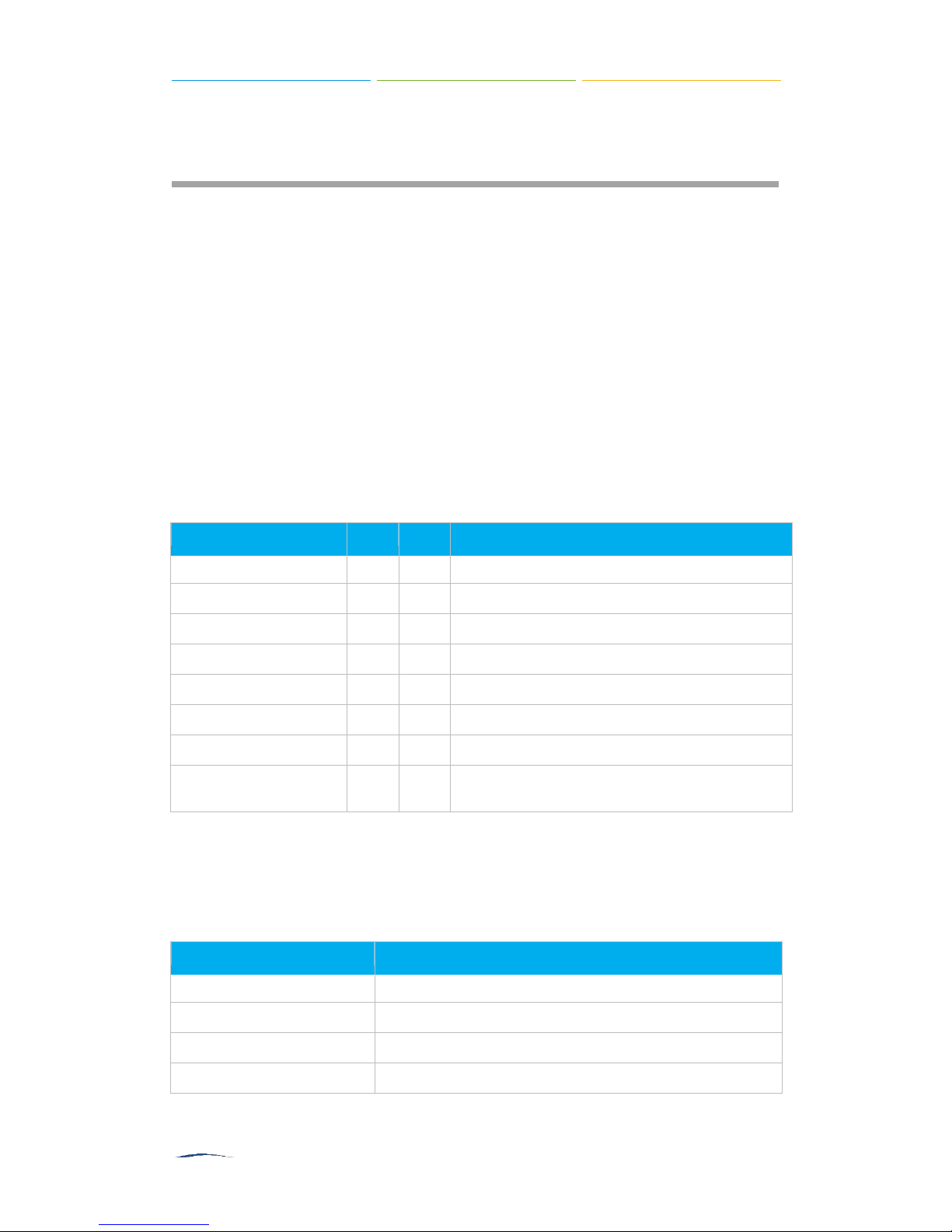
S2400 User Manual
Item
Unit
QTY
Description
S2400
PC 1
S2400 device unit
Power cord
PC 1
For the input of 220V AC power
Network cable
PC 1
Mounting ears
PC 2
Screws
PC 8
8 screws (φ3.0*6 mm) for mounting ears
Grounding stud & nut
Pair 1
Rubber feet
PC 4
Warranty card
PC 1
With Serial Number printed for Repair &
Return
S2400
Descriptio
Size (L×W×H)
440 mm ×250 mm ×44 mm
Power Supply
AC 100-240V 50/60Hz
Operating Temperature
0°C to 40°C, 32°F to 104°F
Storage Temperature
-20°C to 65°C, 4°F to 149°F
Installation
Before getting started with S2400, you need to know how to install the device
properly. This chapter gives detailed installation instructions.
□
S2400 Packing List
□
Specifications and Operating Environment
□
Placement Instructions
□
Connect Your S2400
S2400 Packing List
Upon receiving XonTel S2400 gift box, please open the package and check if all the
items are supplied as S2400 Packing List. If there is any problem, please contact
your provider.
Table 2-1 S2400 Packing List
Specifications and Operating Environment
Table 2-2 Specifications and Operating Environment

S2400 User Manual
Humidity
10% to 90% (non-condensing)
Placement Instructions
To avoid unexpected accident, personal injury or device damage, please read the
following instructions before installing the Gateway.
1. Ambient Temperature: to avoid overheating, please do not run S2400 in the
place where the ambient temperature is above 104°F (40°C).
2. Ventilation: please make sure that the device has good ventilation around.
3. Anti-jamming: there may be some sources of interference that might affect the
normal running of the Gateway. It’s highly recommended that the device
Should be placed away from high-power radio, radar transmitters and high
frequency, and high-current devices.
Is using independent power junction box and effective anti-grid interference
measures have been taken.
4. Mechanical load: Please make sure that the device is placed steadily to avoid any
accident that might cause damage. If placed on the desktop, please ensure it is
horizontally placed.
Connect Your S2400
Connection of Ethernet Ports
S2400 provides one 10/100M adaptive RJ45 Ethernet LAN port.
Connect one end of a network cable to the LAN port of the S2400, and the other end
to any port of company’s LAN switch/router.
Connection of FXO Ports
S2400 supports 8 FXO ports.
Connect the FXO interfaces to the Public TelephoneNetwork (PSTN).
Power Connection
Connect the power cable to the S2400’s powerport, and then plug the power socket
into an electrical outlet.Press the On switch to power on the S2400. The device will
start booting. In the meantime, users would see that the
indicator lights turn on.
―POWER‖
and
―RUN
‖
S2400 User Manual
Please switch off the power before plugging or unplugging the cables.
Connection Diagram
Figure 2-1 S2400 Front Panel Connection Diagram
Figure 2-2 S2400 Rear Panel Connection Diagram
S2400 User Manual
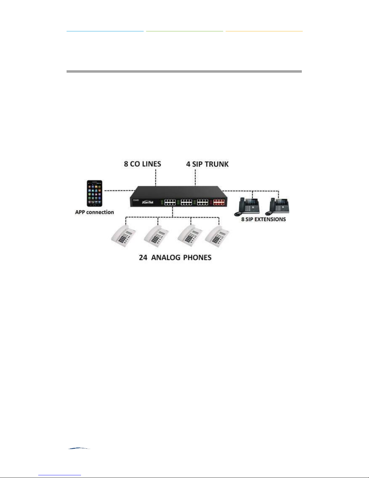
Application Overview
With S2400, in addition to use the functions as traditional PBX, you could expand the
communication flexibly with 4 SIP trunks, 8 SIP extensions. You will enjoy the
as its easy management that you had never experienced on a traditional PBX.
XonTel has developed an App called Linkus for you to access your S2400 wherever
you are with your smart phones, which significantly increase the flexibility and mobility
of your communication.
S2400
Figure 3-1 S2400 Application Overview
S2400 User Manual
Getting Started
In this chapter, we guide you through the basic steps to start with a new
□
Accessing Web GUI
□
Web Configuration Panel
□
User Management
□
Making and Receiving Calls
S2400
:
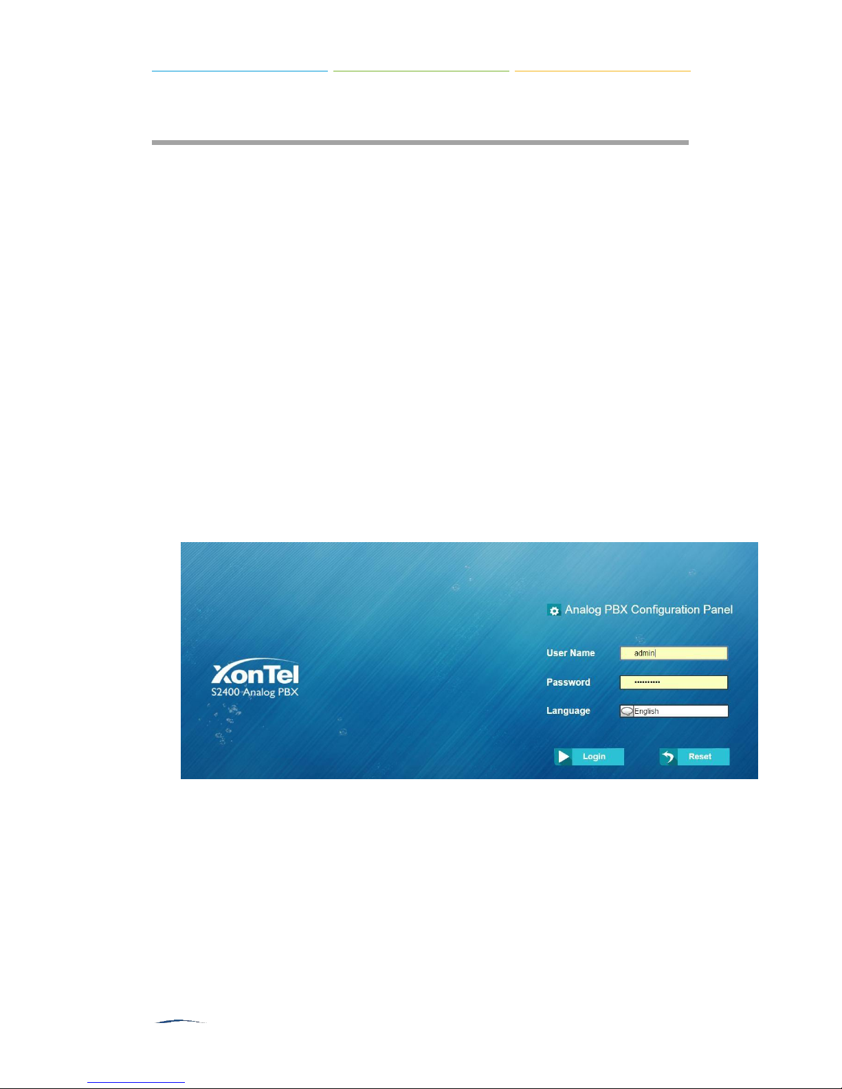
Accessing Web GUI
S2400
The user can manage the device by logging in the Web interface.Check the factory
defaults below:
IP address: http://192.168.5.150
User Name: admin
Default Password: xontel
1. Start the browser on PC. In the address bar, enter the IP address, click
2. Enter the Admin User Name and Password to log in.
provides web-based configuration interface for administrator and account user.
―
Enter‖button and then you can see the Web Configuration Panel login page.
Figure 4-1 S2400 Web Configuration Panel Login Page

S2400 User Manual
Web Configuration Panel
There are 4 main sections on the Web Configuration Panel for users to check the
S2400's
□
□
□
□
status and configure it.
Status:
and CDR.
System:
Time, Password, Backup and Restore, Storage Management, Recording Settings
etc.
PBX:
Settings, Voicemail Settings, SIP Settings etc.
Logout:
check System Status, Extension Status, Trunk Status, Network Status
configure Network Settings, Security related Settings, System Date and
configure extensions, PSTN trunks, Call Routing, Call Features, Audio
log out
S2400
.
Note:
After saving the changes, remember to click the
right of the Web GUI to makethe changes take effect.
―Apply changes‖
button on the upper
User Management
S2400 supports two user types with different privileges.
User Privileges
□
Administrator
pages on
Username: admin
Default Password: xontel
has the highest privilege. The administrator can access all
S2400
Web and make all the configurations on the system.
□
Extension User
auto recordings and CDR. The user can also configure settings and wake-up call
for his own extension.
Username: Extension number (i.e.601)
Default Password: generation password
has the privilege to check voicemails, one-touch recordings,
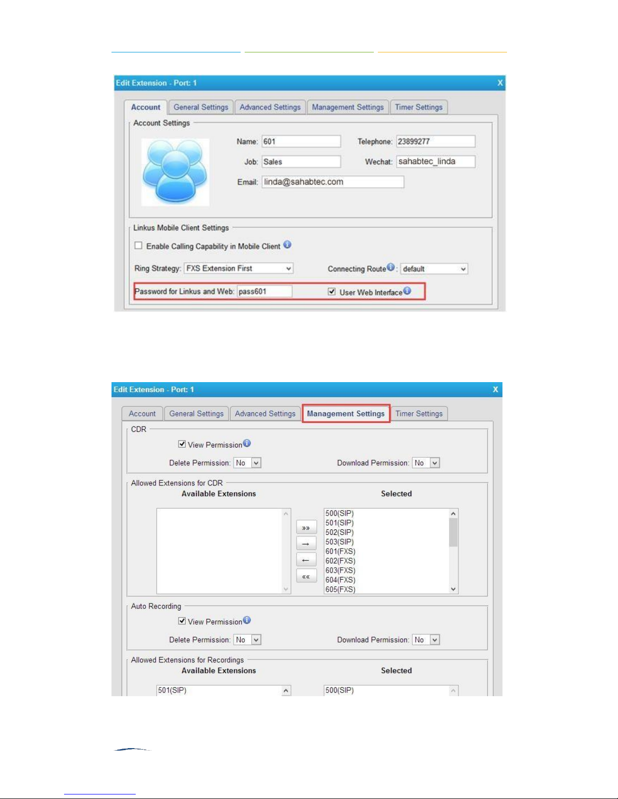
Enable Extension User
To log in
Interface
Login
extension and click edit, check the
S2400
S2400
Web GUI using Extension User, you need to enable
option for the extension.
, go to
PBX→Extensions
and
Trunks→Extensions
User Web Interface
options on
User Web
, choose an
Account
tab.
S2400 User Manual
Figure 4-2 Enable Extension User
Set the privileges of CDR check and Auto Recording check on
Settings
tab.
Management
Figure 4-3 Management Settings

S2400 User Manual
Making and Receiving Calls
S2400 is ready to play out of the box with plug-and-play facility. Power on the device
and connect analog phones and CO lines, you can make internal calls, outbound calls
and inbound calls with
Note:
To custom the configurations according to your situation, you have to connect the
network cable to
□
Internal calls between extensions
Connect analog phones to FXS ports on
extensions just by dialing the other’s extension number. If IP terminals have
registered to
extensions.
Default FXS extension number: 601-624.
□
Outbound calls
Firstly, please connect CO lines to CO ports on S2400. Then the default
extensions are able to seize an available CO line to make outbound calls. Users
could dial digit 9 to seize a CO line first, and dial the external number after
hearing a dial tone.
Users could also use the default outgoing rule to make outbound calls. The dial
pattern of the default outbound route is
8 before the number.
S2400
.
S2400
, then log in the web user interface to change the settings.
S2400
, users could make calls between
S2400
successfully, users could also make internal calls using SIP
―8.‖and strip 1 digit, users should dial digit
□
Inbound calls
When the user calls the trunk number of the CO lines, S2400 would route the call
to the analog phone which is connected to the port EXT1.
S2400 User Manual
Items
Description
DHCP
If this option is set as yes, S2400 will act as DHCP client
to get an available IP address from your local network. We
don’t recommend enabling this, as without the right IP
addressyou cannot access XonTel S2400 PBX.
Enable SSH
By using SSH, you can log in to S2400 and run
commands. It’s disabled by default. We don’t recommend
enabling it if not needed.
Default Port: 8022.
Enable FTP
Users could log in S2400 via FTP if this option is enabled.
Users could access FTP resource on S2400 via Windows
System Settings
This chapter explains system settings on S2400. Click the main menu
top of the Web GUI to check the system settings.
□
Network Settings
□
Security Center
□
Date and Time
□
Password Settings
on the
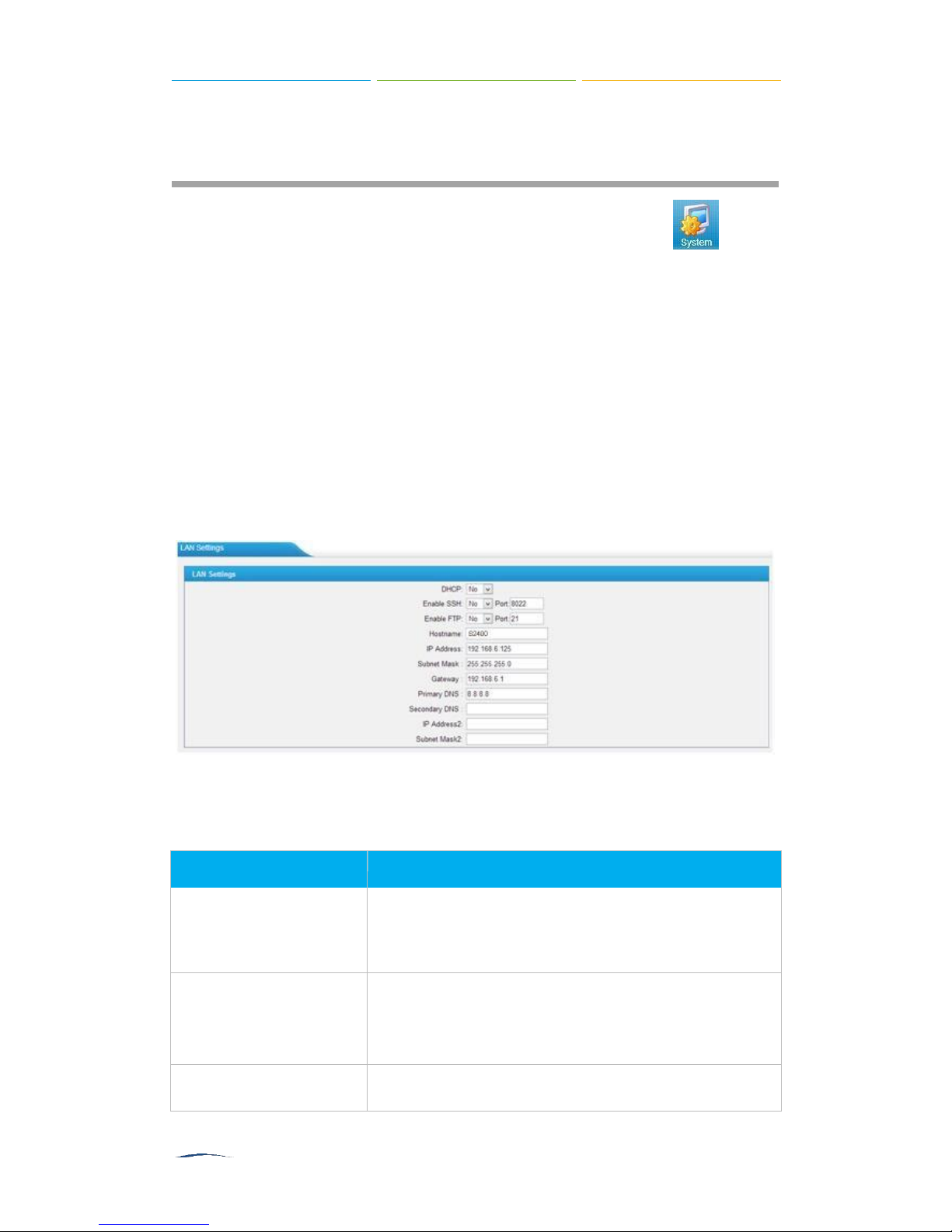
Network Settings
After successfully logging in the S2400 Web GUI for the first time with the factory IP
address, users could go
configure the network for S2400.
System→Network Preferences→LAN Settings
to
Figure 5-1 LAN Settings
Table 5-1 LAN Settings
S2400 User Manual
explorer or Web browser.
FTP default user: root, password: xontel262
Default Port: 21.
Hostname
Set the host name for S2400.
IP Address
Set the IP Address for S2400.
Subnet Mask
Set the subnet mask for S2400.
Gateway
Set the gateway for S2400.
Primary DNS
Set the primary DNS for S2400.
Secondary DNS
Set the secondary DNS for S2400.
IP Address2
Set the second IP Address for S2400.
Subnet Mask2
Set the second subnet mask for S2400.
Security Center
Users are strongly recommended to configure firewall and other security options
on S2400 to prevent the attack fraud and the system failure or calls loss.
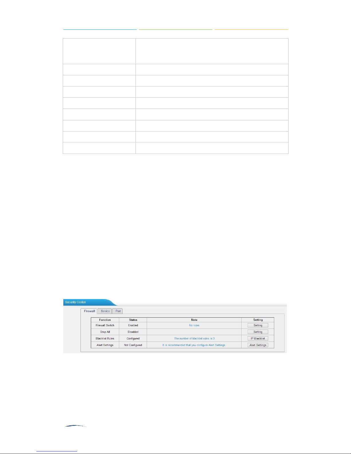
Security Center
All the security settings including Firewall, Service, Port Settings in S2400 are
displayed in Security Center. Users could rapidly check and configure the relevant
security settings here.
Firewall
In the
clicking the relevant button, you can enter the configuration page directly.
―Firewall‖
tab, users could check firewall configuration and alert settings. By
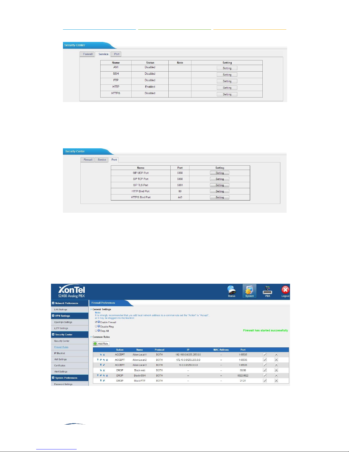
Service
In
according page by clicking the button in
―Service‖
tab, you can check AMI/SSH status. For AMI/SSH, you can enter the
Figure 5-2 Security Center—Firewall
―Setting‖
column.
S2400 User Manual
Figure 5-3 Security Center—Service
Port
In
―Port‖
page by clicking the button in
tab, you can check SIP port and HTTP port. You can also enter the relevant
―Setting‖
column.
Figure 5-4 Security Center—Port
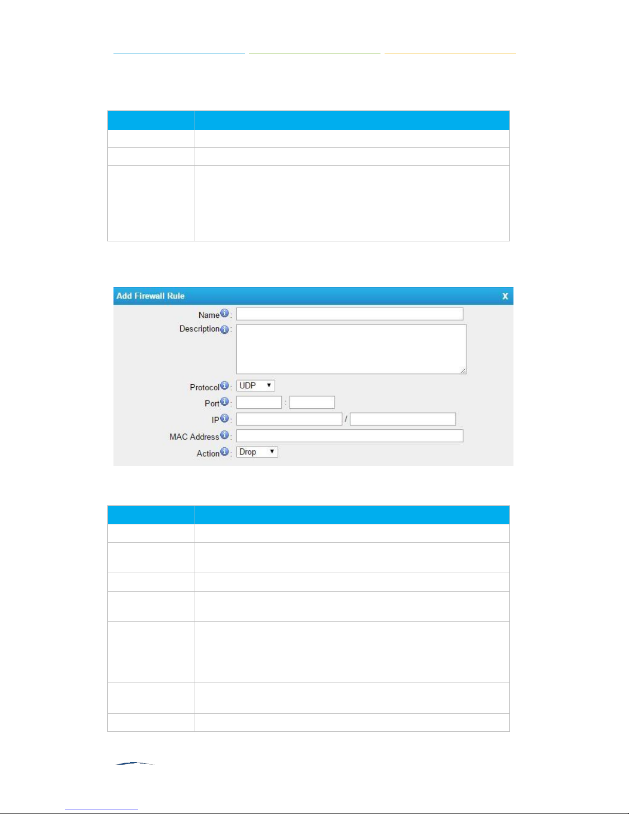
Firewall Rules
Firewalls are used to prevent unauthorized Internet users from accessing private
networks connected to the Internet, especially intranets. All messages entering or
leaving the intranet pass through the firewall, which examines each message and
blocks those that do not meet the specified security criteria.
Figure 5-5 Firewall Settings
S2400 User Manual
Items
Description
Enable Firewall
Enable the firewall to protect the device.
Disable Ping
Enable this item to drop net ping from remote hosts.
Drop All
When you enable
―Drop All‖
feature, the system will drop all packets
or connection from other hosts if there are no other rules defined. To
avoid locking the devices, at least one
―TCP‖
accept common rule
must be created for port used for SSH access, port used for HTTP
access and port sued for CGI access.
Items
Description
Name
A name for this rule, e.g.
―HTTP‖.
Description
Simple description for this rule. E.g. accept the specific host to
access the Web interface for configuration.
Protocol
The protocols for this rule.
Port
Initial port should be on the left and end port should be on the right.
The end port must be equal to or greater than start port.
IP
The IP address for this rule. The format of IP address is: IP/mask
E.g. 192.168.5.100/255.255.255.255 for IP 192.168.5.100
E.g. 192.168.5.0/255.255.255.0 for IP from 192.168.5.0to
192.168.5.255.
MAC Address
The format of MAC Address is XX:XX:XX:XX:XX:XX, X means 0~9
or A~F in hex, the A~F are not case sensitive.
Action
Accept: Accept the access from remote hosts.
1)
General Settings
Table 5-2 Description of Firewall General Settings
2)
Common Rules
There is no default rule; you can create oneas required.
Figure 5-6 Common Rules
Table 5-3 Description of Common Rules

S2400 User Manual
Drop: Drop the access from remote hosts.
Ignore: Ignore the access.
Items
Description
Port
The port you want to auto defense, for example, 8022.
Protocol
Select the protocol. You can select UDP or TCP.
Rate
The maximum packets or connections can be handled per unit
time.For example, if you configure it as below:
Port: 8022
Protocol: TCP
Rate: 10/min
Then, it means maximum 10 TCP connections can be handled in
1 minute. The 11th connection will be dropped.
Note
: the MAC address will be changed when it’s a remote device, so it will not be
working to filter using MAC for remote devices.
3)
Auto Defense
Figure 5-7Auto Defense
Table 5-4 Description of Auto Defense
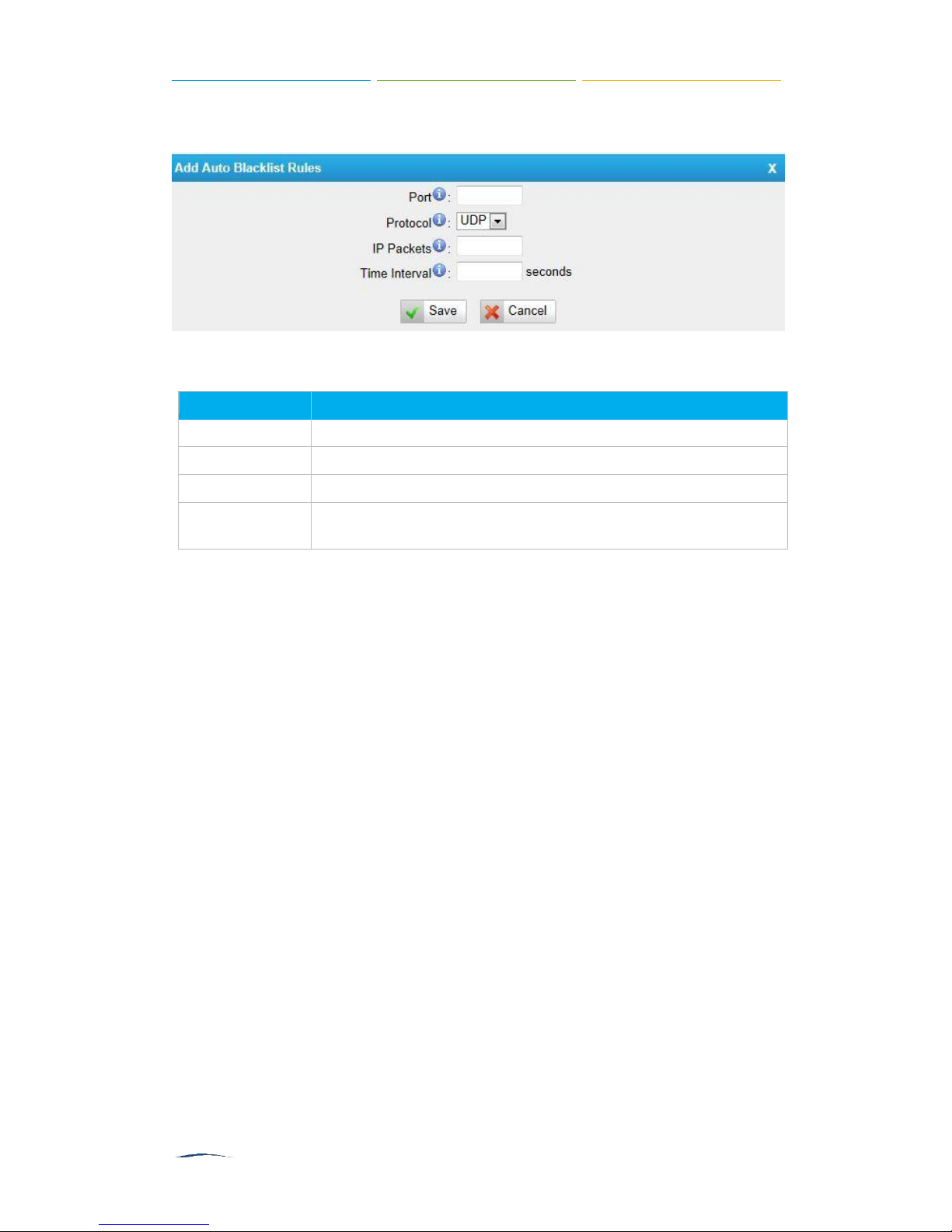
IP Blacklist
You can set some packets accept speed rules here. When an IP address, which
hasn’t been accepted in common rules, sends packets faster than the allowed speed,
it will be set as a black IP address and be blocked automatically.
Figure 5-8 IP Blacklist Settings Page
S2400 User Manual
Items
Description
Port
Auto defense port
Protocol
Auto defense protocol. TCP or UDP.
IP Packets
Allowed IP packets number in the specific time interval.
Time interval
The time interval to receive IP packets. For example, IP packets 90,
time interval 60 means 90 IP packets are allowed in 60 seconds.
1)
Blacklist rules
We can add the rules for IP blacklist rate as demanded.
Figure 5-9 Add Blacklist Rule
Table 5-5 Description of Auto Blacklist Rules
2)
IP blacklist
The blocked IP address will display here, you can edit or delete it as you wish.
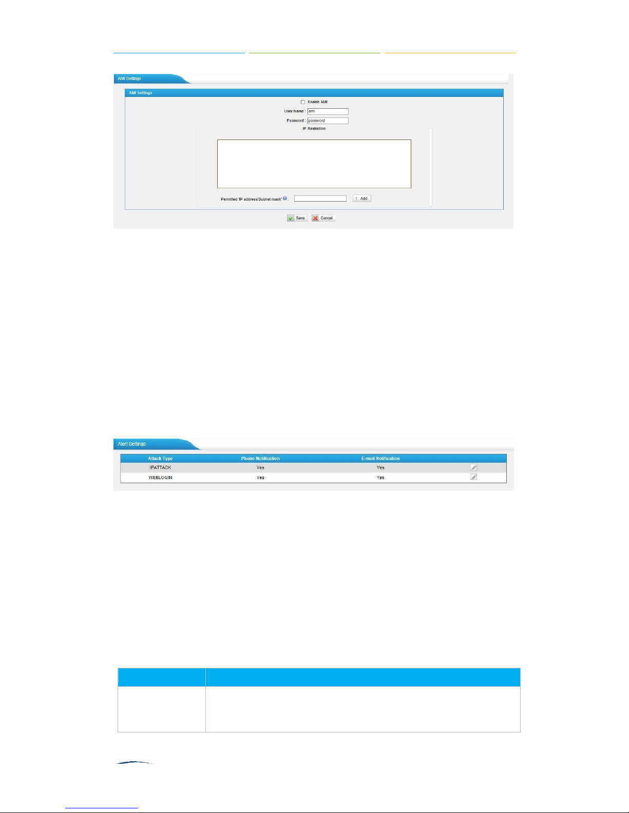
AMI Settings
The Asterisk Manager Interface (AMI) is a system monitoring and management
interface provided by Asterisk. It allows live monitoring of events that occur in the
system, as well enabling you to request that Asterisk perform some action. The
actions that are available are wide-ranging and include things such as returning status
information and originating new calls. Many interesting applications have been
developed on top of Asterisk that take advantage of the AMI as their primary interface
to Asterisk.
There are two main types of messages on the Asterisk Manager Interface: manager
events and manager actions.
The 3rd party software can work with S2400 using AMI interface. It is disabled by
default. If necessary, you can enable it.
S2400 User Manual
Items
Description
Number
The numbers could be set for alert notification; users can setup
multiple extension and outbound phone numbers. Please
separate them by
―;‖.
Figure 5-10 AMI Settings
□
Username & password
After enabling AMI, you can use this username and password to log in S2400
AMI.
□
IP Restriction
You can set which IP is allowed to log in S2400 AMI interface.
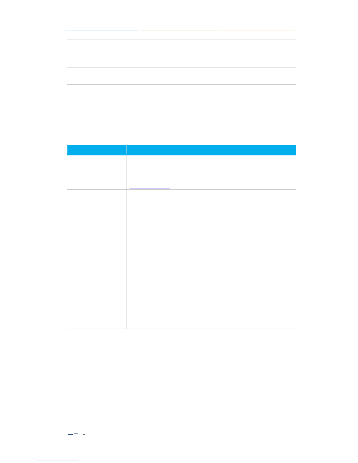
Alert Settings
After enabling this feature, phone notification or email notification will be sent to users
if the system has been attacked via IP or Web.
Figure 5-11 Alert Settings
□
IPATTACK
When the system is attacked by IP address, the firewall will add the IP to auto IP
Blacklist and notify the user if it match the protection rule.
□
WEBLOGIN
Web Login Alert Notification: enter the incorrect password consecutively for five
times will be considered as an attack, the system will limit the IP login within 10
minutes and notify the user.
1)
Phone Notification Settings
Table 5-6 Description of Phone Notification Settings
S2400 User Manual
Example:
―500;991
1‖, if the extension has configured Follow Me
Settings, the call would go to the forwarded number directly.
Attempts
The attempts to dial a phone number when there is no answer.
Interval
The interval between each attempt to dial the phone number.
Must be greater than 3 seconds, the default value is 10 seconds.
Prompt
Users will hear the prompt while receiving the phone notification.
Items
Description
Recipient’s Name
The recipients for the alert notification, and multiple email
addresses are allowed, please separate them by
―;‖.
Example:jerry@XonTel.com;jason@XonTel.com,
456@sina.com .
Subject
The subject of the alert email.
Email Content
Text content supports predefined variables. Variable names and
corresponding instructions are as follows:
$(HOSTNAME) Host name
$(LOCALIP) Local IP address
$(SOURCEIP) Attack source IP address
$(DATETIME) Occurred
$(USERNAME) User name (WEBLOGIN effective)
$(DESTMAC) Attacks destination MAC (IPATTACK
effective)
$(DESTPORT) Attacks destination Port number (IPATTACK
effective)
$(PROTOCOL) Protocol type (IPATTACK effective)
$(INTERFACE) Network interface name (IPATTACK
effective)
2)
Email Notification Settings
Please ensure that all voicemail settings are properly configured on the
PBX→Basic Settings→Voicemail Settings
page before using this feature.
Table 5-7 Description of Email Notification Settings
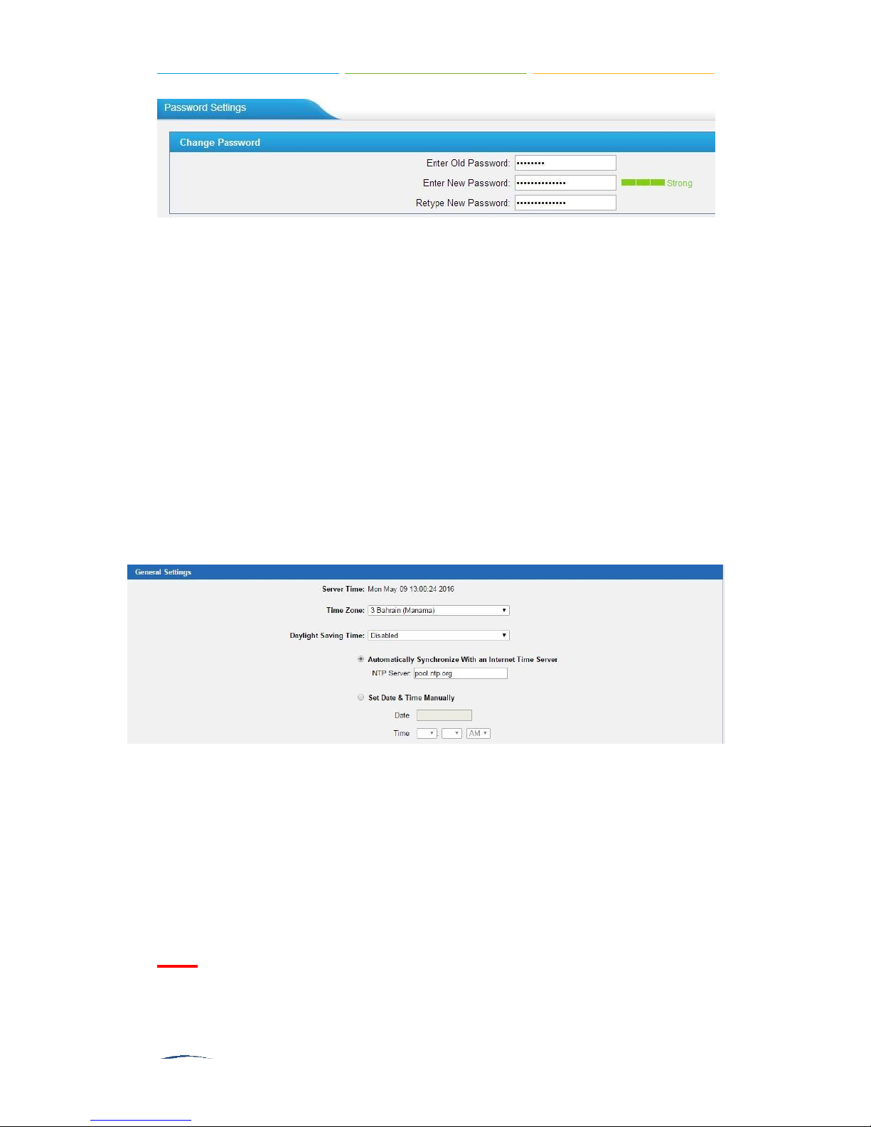
Password Settings
It is highly recommended to change the system’s password after first login. Go to
System→System Preferences→Password Settings
to change the password.
S2400 User Manual
Figure 5-12 Change Password
1. Enter the old password first.
2. Enter a new password and retype the new password to confirm. The password
complexity will be detected, which will help users to set a strong password and
make S2400 safer. A strong password is comprised of letters, numbers and
characters.
3. Save the changes, the user will be automatically logged out.
4. Log in S2400 using the new password.
Date and Time
Please adjust the time of S2400 (including the time zone) consistent with your local
time. Go to
date and time.
System→System Preferences→Date and Time
to configure the system
□
Time Zone
Select your current and correct time zone on S2400.
□
Daylight Saving Time
The option is disabled by default. Enable it when necessary.
□
Automatically Synchronize with an Internet Time Server
S2400 will adjust its internal clock to a central network server. Please note
the S2400 should be able to access to the Internet if you choose this method.
□
Set Date & Time Manually
Enter the time using the numbers on your keyboard.
Note:
You have to reboot the system to make the changes take effect.
Figure 5-13 Configuring Date & Time
S2400 User Manual
Extensions
This chapter explains how to create and configure extensions on S2400. It supports
SIP extensions and FXS extensions, go to
Extensions
□
FXS Extensions
□
VoIP Extensions
page to configure the extensions.
FXS Extensions
There are 24 FXS extensions on S2400. Users could click to edit each FXS
extension.
FXS Extension Configuration
The extension settings are divided into Account, General Settings, Advanced Settings,
Management Settings and Timer Settings.
PBX→ Extensions and Trunks →
1)
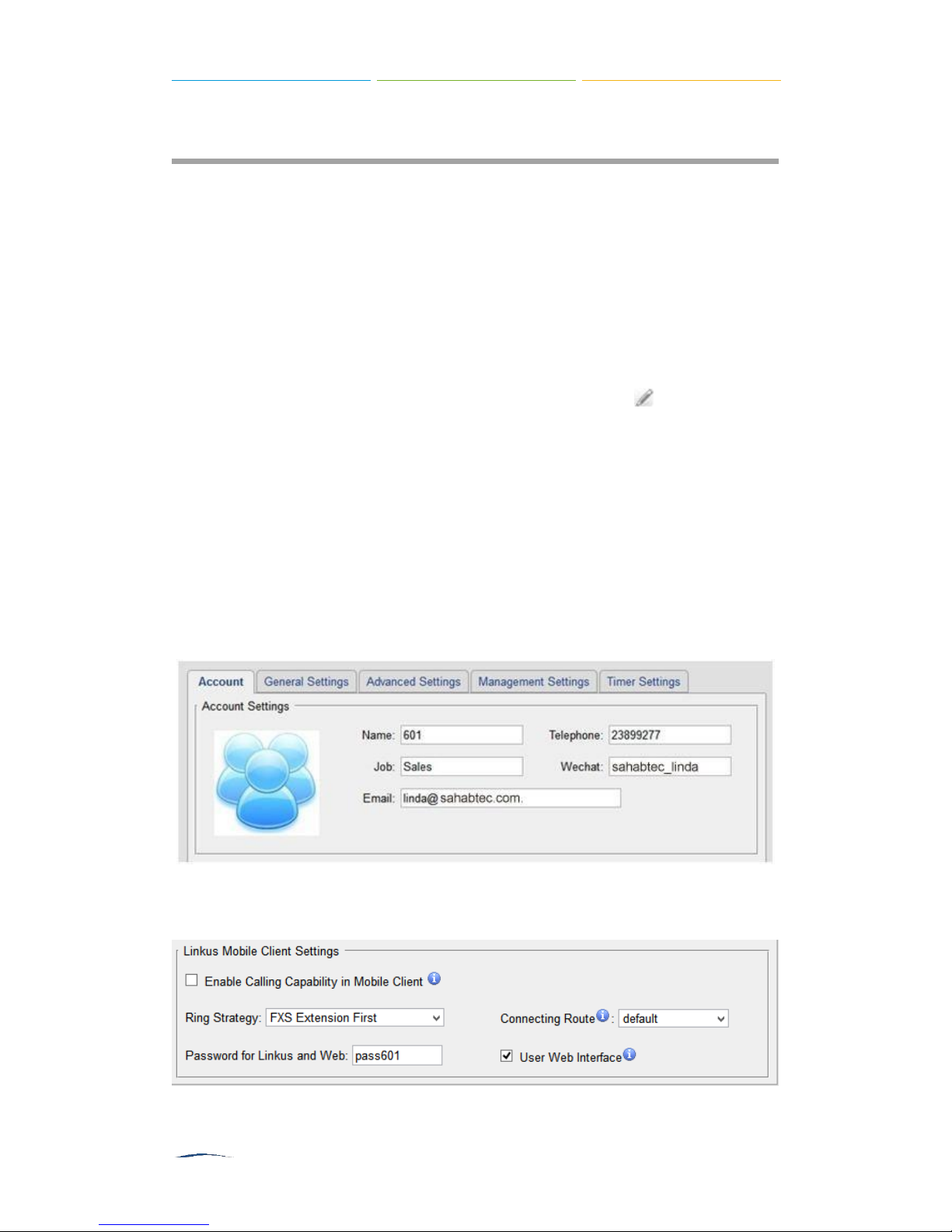
Account
On this page, users could fill in the user information, including Name, Telephone
number, Job, Wechat ID and Email address. If an image of the account was uploaded
via the Linkus App, you could see the account’s image here.
Figure 6-1 Account Information
Configure
Linkus App.
Linkus Mobile Client Settings
if you want to register this extension to the
Figure 6-2 Linkus Mobile Client Settings
S2400 User Manual
Items
Description
Enable Calling
Capability in Mobile
Client
Allow the user to make and receive calls with Links Mobile
Client. Please make sure that the corresponding App has been
installed on your phone.
Ring Strategy
Set ring strategy between the FXS extension and mobile
extension.
FXS Extension First
Mobile Client Extension First
Connecting Route
The route is used to connect Linkus and the PBX, so S2400
will always use this route to dial Linkus.
Password for Linkus
and Web
The password to register mobile extensions and log in the user
Web interface.
User Web Interface
Check this option to allow the user to login to the S2400
User Web interface, which can be used to check voicemail
and extension recordings.
Items
Description
Extension
The numbered extension, which will be associated with this
particular User/Phone.
Caller ID
The Caller ID will be used when this user calls another internal
extension.
Voicemail
Enable Voicemail
Enable voicemail for the user.
Voicemail Access PIN
The voicemail password (digits only) for the user to access
the voicemail box.
Mail Settings
Enable Send Voicemail
Once enabled, the voicemail will be sent to a configured
email address.
Hotline
Enable Hotline: whether to use hotline.
Hotline Number: set a hotline number.
Delay Dial: define how long to make Hotline call after you
pick up the call.
Flash
Sets the minimum/maximum time the phone is on hook before
being detected as a hook flash.
Pickup Group
If this extension belongs to a pickup group, any calls that ring
this extension can be picked up by other extensions in the same
pickup group by dialing the Call Pickup feature code (the default
is *4).
Table 6-1 FXS Extension Linkus Mobile Client Settings
2)
General Settings
Table 6-2 FXS Extension Configuration- General Settings

S2400 User Manual
Note: *4 is the default setting, it can be changed under Feature
Codes→ General → Call Pickup.
Max Call Duration
Setup the max cull duration for every call of this extension, but
it’s only valid for outbound calls. Enter
―0‖ or leave this blank
empty, the value would be equal to the max call duration
configured in the Option Settings page.
Note: this setting will not be valid for internal calls.
Items
Description
Call Waiting
Check this option if the extension should have Call Waiting
capability. If this option is checked, the
―When busy‖
follow me
options will not be available. The call waiting function of IP
phone has higher priority than S2400’s call waiting function.
DND
Don’t Disturb. When DND is enabled for an extension, the
extension will not be available.
Enable Busy
Camp-on
If a dialed extension or a desired line is busy, with this feature,
when the extension or line becomes idle, your telephone will ring
automatically, so you can pick up to speak with the extension or
seize the line and dial an external number.
Ring Out
Check this option if you want to customize the ring time. Ring
tone will stop over the time defined.
Follow me
Call forwarding for an extension can be configured here. The
administrator can configure Follow Me option for this extension.
If you want to transfer the call to an outbound number, please
follow the dial pattern of outbound route filled in the outbound
number.
For example: transferring to your mobile phone number
123456789, the dial pattern of outbound route is
―9.‖, you should
fill in 9123456789 here.
Volume Settings
Rxgain
The Volume sent to FXS extension.
Txgain
The Volume sent out by the FXS extension.
Caller ID Type
Normally, you choose the
―default‖
option except for using
S2400 in Japan, in which case you should choose
―Jap
an‖.
Spy Settings
There are 4 spy modes available:
General spy
You have the permission to use the following 3 modes.
Normal spy
You can only hear the call, but can't talk
Whisper spy
3)
Advanced Settings
Table 6-3 FXS Extension Configuration- Advanced Settings

S2400 User Manual
You can hear the call, and can talk with the monitored
extension
Barge spy
You can hear the call and talk with them both
Example:
If 500 want to monitor extension 501, we need to enable the
―
allow being spied‖
for 501, and choose the spy mode for
extension 500.
Then pick up 500 and dial
―feature codes + 5
01‖ to
start
monitoring when 501 is in a call.
If 500 choose
―normal spy‖, it should dial
―*905
01‖ to
start
monitoring.
If 500 choose
―whisper spy‖, it should dial
―*91501‖ to
start
monitoring.
If 500 choose
―barge spy‖, it should dial
―*92501‖ to
start
monitoring.
If 500 choose
―general spy‖, it can dial
―*9050
1‖,
―*91501‖
or
―*92501‖ to
start monitoring.
4)
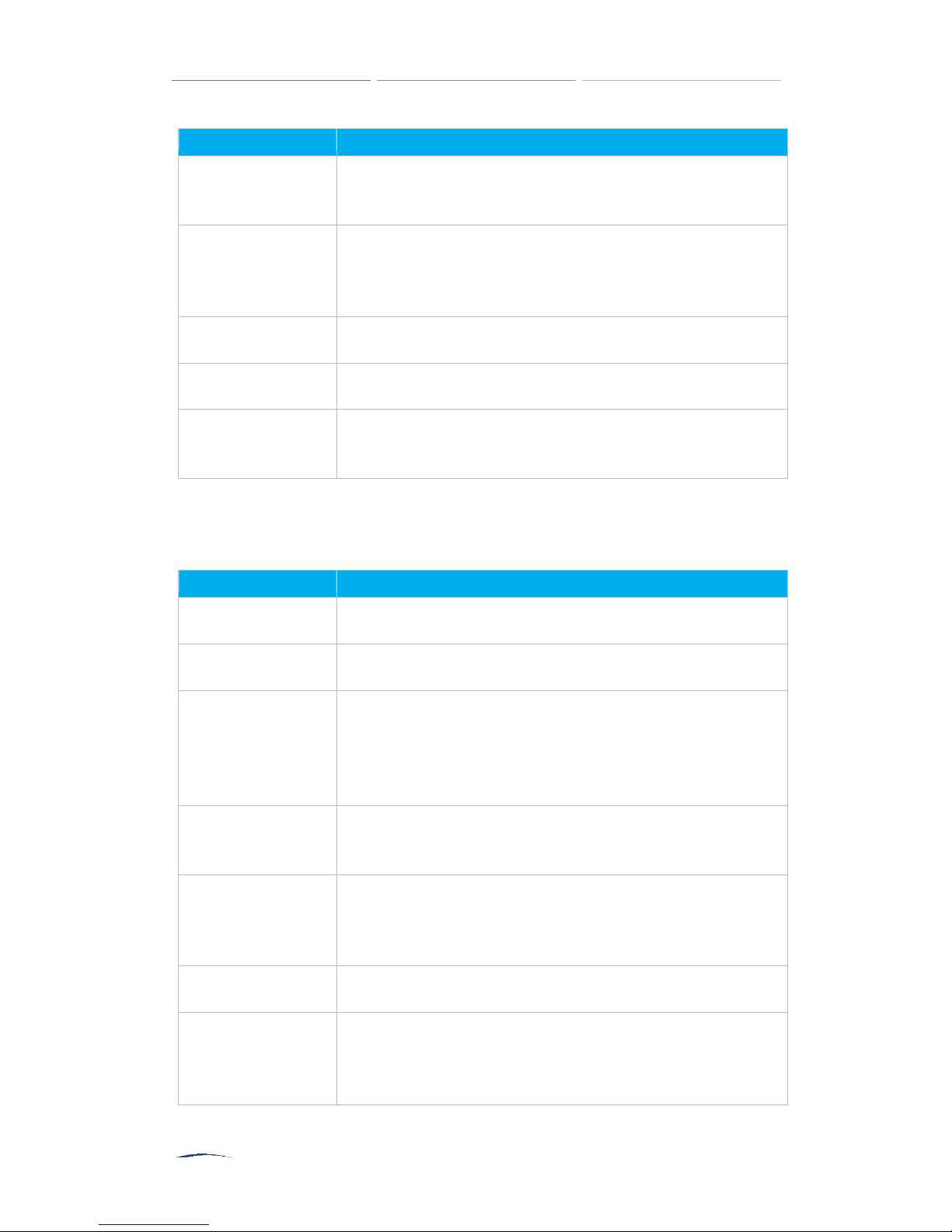
Management Settings
Once you enable
configure the Management settings to set the access permissions.
By default, extension users could check voicemail, one-touch Recordings, and
configure settings of their own extensions when logging in User Web Interface.
If the user wants to manage the CDR and Auto Recordings, you have to set the
access permissions here.
―User Web Interface‖
CDR
View Permission: the permission to view CDR.
Delete Permission: the permission to delete CDR.
Download Permission: the permission to download CDR.
Allowed Extension for CDR: choose which extensions’ CDR is allowed to be
checked/deleted/downloaded by the user.
for the extension, you need to also
S2400 User Manual
Figure 6-3 CDR Permissions for FXS Extensions
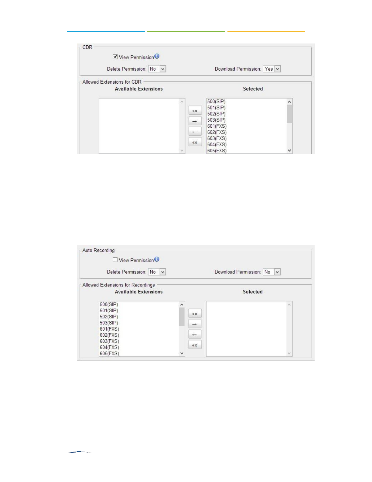
Auto Recordings
View Permission: the permission to check auto recordings.
Delete Permission: the permission to delete recording files.
Download Permission: the permission to download auto recording files.
Allowed Extension for Recordings: choose which extensions’ auto recording
files are allowed to be checked/deleted/downloaded by the user.
Figure 6-4 Auto Recordings Permissions for FXS Extensions
5)
Timer Settings
Want the phone to wake you? Click Timer Settings Section, set your wake-up time
and other options, and give the alarm a name (like
―Good mornin
g‖).
 Loading...