

X O N O X
T e ch n o l o g y G m bH / / 3 5 6 2 5 H u e t t e n b e rg / /G e rm a n y
Operating Manual
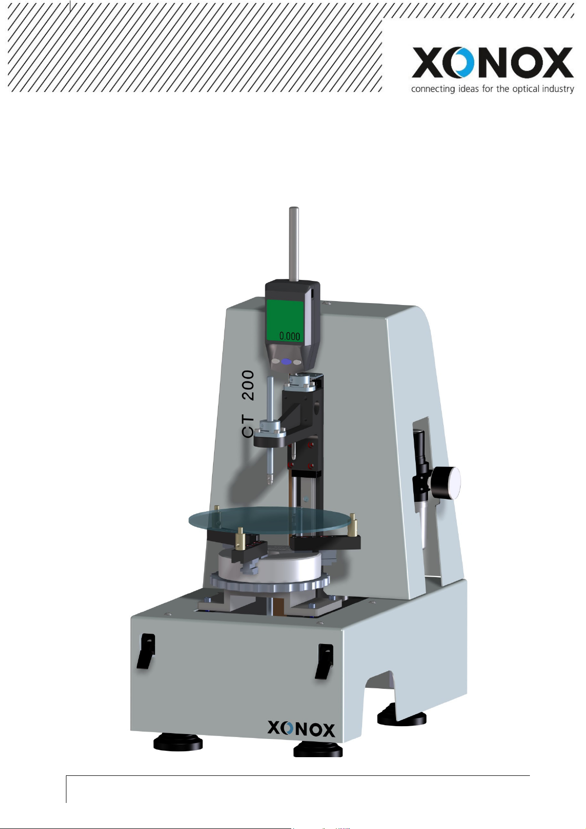
XONOX CT 200
P h o n e + 4 6 6 4 4 1 9 6 3 6 4 0 / / F a x + 4 9 6 4 4 1 9 6 36 4 10 / / w w w . x o n ox - t e c . c o m

X O N O X
T e ch n o l o g y G m bH / / 3 5 6 2 5 H u e t t e n b e rg / /G e rm a n y
P h o n e + 4 6 6 4 4 1 9 6 3 6 4 0 / / F a x + 4 9 6 4 4 1 9 6 36 4 10 / / w w w . x o n ox - t e c . c o m

X O N O X
T e ch n o l o g y G m bH / / 3 5 6 2 5 H u e t t e n b e rg / /G e rm a n y
Operating Manual CT 200
Content
1.
General ........................................................................................................................ 4
1.1. General instructions .................................................................................................................................. 4
1.2. Scope of supply ......................................................................................................................................... 4
2.
Product description ....................................................................................................... 5
2.1. Configuration ............................................................................................................................................ 5
2.2. Operation elements .................................................................................................................................. 6
3.
Installation ................................................................................................................... 7
3.1. Adjustment ................................................................................................................................................ 7
3.1.1. Adjustment of the Lenses...................................................................................................................... 7
3.1.2. Adjustment of the upper and lower measuring key button ................................................................. 8
3.2. Alignment .................................................................................................................................................. 9
4.
Safety Instructions ...................................................................................................... 10
4.1. General safety instructions ..................................................................................................................... 10
5.
Function and measurement ........................................................................................ 11
5.1. Function of the measuring gauge ............................................................................................................ 11
5.2. Calibration ............................................................................................................................................... 11
5.3. Measuring procedure .............................................................................................................................. 12
5.4. Using the probe tips 12
6.
Appendix .................................................................................................................... 13
6.1. Technical Data ......................................................................................................................................... 13
6.2. Pneumatic plan ....................................................................................................................................... 14
P h o n e + 4 6 6 4 4 1 9 6 3 6 4 0 / / F a x + 4 9 6 4 4 1 9 6 36 4 10 / / w w w . x o n ox - t e c . c o m
Page 3 of 14

1. General
1.1. General instructions
Dear Customer,
always keep the instruction manual near to the XONOX CT 200.
Only qualified people are allowed to use the XONOX CT 200.
1.2. Scope of supply
The scope of supply consists of:
-
- XONOX CT 200
- 3x lens support tips short
-
- 3x lens support tips long
- Respective holder
- Gauge block 10mm
- Probe tips 1x steel plan, 2x PEEK 5mm, 2x PEEK 3mm
- Alignment bushing
- Combination pliers
- Allen key 3mm
- Mitutoyo digital gauge 543-564D + remote control
Operating Manual CT 200
General
Page 4 of 14
Ph o ne +4 6 6 4 4 1 9 6 3 6 4 0 / / F a x + 4 9 6 4 4 1 9 6 3 64 1 0/ / w w w . x o n o x- t e c . c o m
X O N O X T e c h n o l og y G m b H / / 3 5 6 2 5 H u e t t e n b e rg / /G e rm a n y
X O N O X
T e ch n o l o g y G m bH / / 3 5 6 2 5 H u e t t e n b e rg / /G e rm a n y
Operating Manual CT 200
Product description
2. Product description
2.1. Configuration
1
7
9
2
3
8
5
4
6
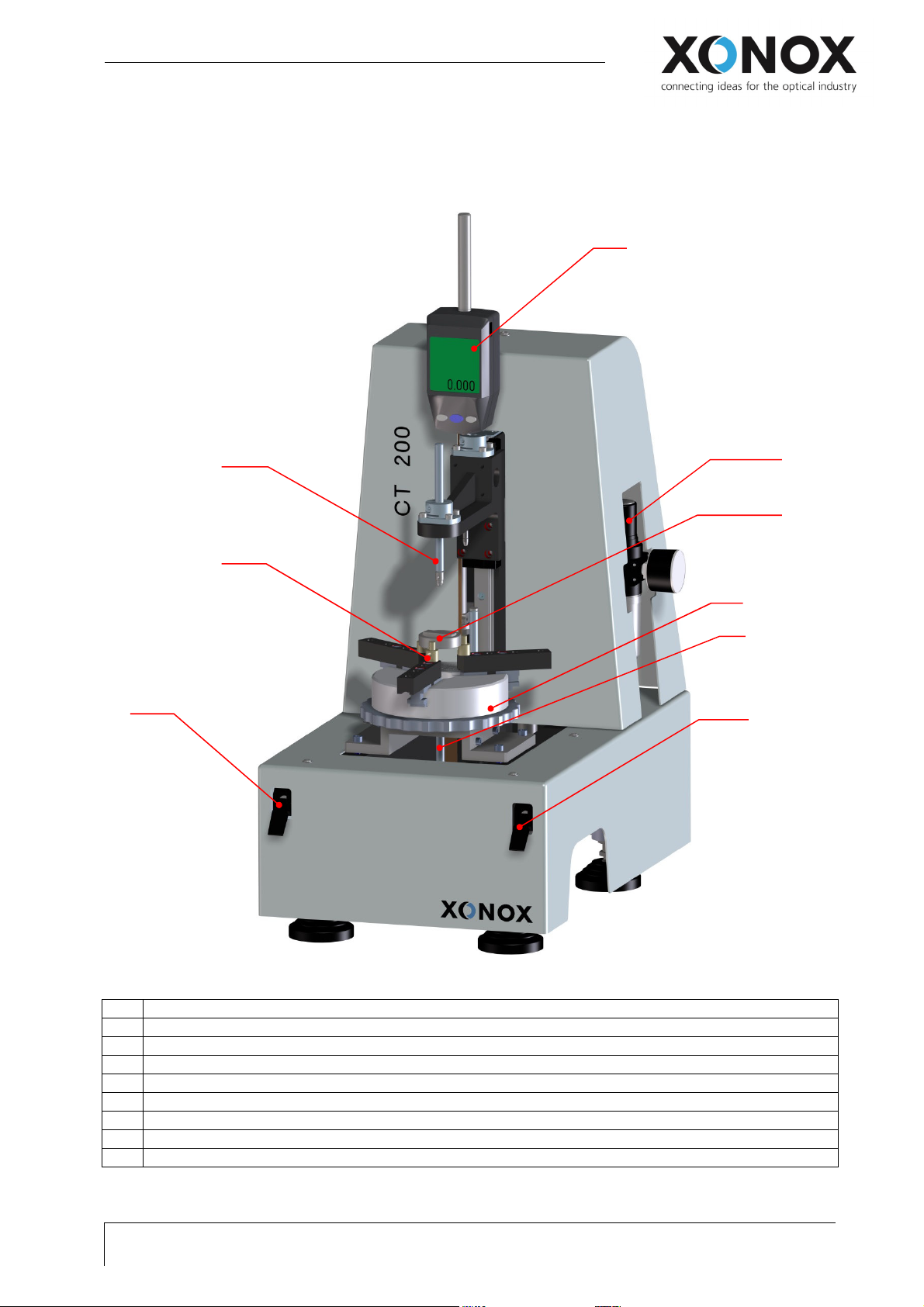
Illustration 1: XONOX CT 200 exposition with inscription
1 Mitutoyo digital gauge 543-564D
2 Input valve (pneumatic)
3 Respective holder + gauge block 10mm
4 Lower probe
5 Manual chuck
6 Switch lower probe UP/DOWN
7 Switch upper probe UP/DOWN
8 Holding adapter for lenses
9 Upper probe
P h o n e + 4 6 6 4 4 1 9 6 3 6 4 0 / / F a x + 4 9 6 4 4 1 9 6 36 4 10 / / w w w . x o n ox - t e c . c o m
Page 5 of 14

2.2. Operation elements
Operating Manual CT 200
Product description
Mituoyo digital gauge 543-564D
- Turn on and off
- Display for indication of measurements
- Adjustment Preset:
See chapter 5.1 or
operating manual measuring gauge 543-564D
Remote control for Mitutoyo digital gauge 543-564D
Manual chuck
centering the lens
Switch for the upper probe
UP / DOWN
Switch for the lower probe
UP / DOWN
Page 6 of 14
Ph o ne +4 6 6 4 4 1 9 6 3 6 4 0 / / F a x + 4 9 6 4 4 1 9 6 3 64 1 0/ / w w w . x o n o x- t e c . c o m
X O N O X T e c h n o l og y G m b H / / 3 5 6 2 5 H u e t t e n b e rg / /G e rm a n y

X O N O X
T e ch n o l o g y G m bH / / 3 5 6 2 5 H u e t t e n b e rg / /G e rm a n y
2a
2b
Operating Manual CT 200
Installation
3. Installation
3.1. Adjustment
3.1.1. Adjustment of the Lenses
1
1. Holding adapter for lenses
2. Manual chuck
3. Adapter for manual chuck
3
2
Illustration 2: Centering device without lens
3
Illustration 3: Change position of holding adapter for lenses
1
2
3
1. Front position oft he holding Adapter for
lenses
2. Change position, depending on lens
diameter
3. Thread for holding adapter for lenses
1. Open the manual chuck
2. attaching the lens
3. Clamp the lens by softly closing the
manual chucks
Illustration 4:Holding oft he lens
P h o n e + 4 6 6 4 4 1 9 6 3 6 4 0 / / F a x + 4 9 6 4 4 1 9 6 36 4 10 / / w w w . x o n ox - t e c . c o m
Page 7 of 14

1
3.1.2. Adjustment oft he upper and lower measuring key button
2
Operating Manual CT 200
Installation
1. Release the clamping
2. Adjust the measuring key
3. Lock the clamping
1;3
Illustration 5: Adjusting the upper probe
1. Hold the lower probe
2. Release the probe
3. Adjust the lower probe
4. Lock the clamping
2;4
3
Illustration 6: Adjust the lower probe
Page 8 of 14
Ph o ne +4 6 6 4 4 1 9 6 3 6 4 0 / / F a x + 4 9 6 4 4 1 9 6 3 64 1 0/ / w w w . x o n o x- t e c . c o m
X O N O X T e c h n o l og y G m b H / / 3 5 6 2 5 H u e t t e n b e rg / /G e rm a n y

X O N O X
T e ch n o l o g y G m bH / / 3 5 6 2 5 H u e t t e n b e rg / /G e rm a n y
Operating Manual CT 200
Installation
3.2. Alignment
2
1
3
1. loose the 4 screws of the adapter for the manual
chuck.
2. Insert the alignment bushing
3. Putting down the upper probe
4. Adjust the manual chuck until upper probe fits
easily through the alignment bushing..
5. tighten the screws of the adapter fort he manual
chuck
Illustration 7: Centering by using the alignment bushing
P h o n e + 4 6 6 4 4 1 9 6 3 6 4 0 / / F a x + 4 9 6 4 4 1 9 6 36 4 10 / / w w w . x o n ox - t e c . c o m
Page 9 of 14

4. Safety Instructions
4.1. General safety instructions
Only qualified people are allowed to use the XONOX CT 200.
While measuring do not put any extremity in operation range (see picture at the bottom).
Consider the risks of injury (cuts) and crushing.
Operating Manual CT 200
Safety Instructions
Illustration 8: area of danger
Page 10 of 14
Ph o ne +4 6 6 4 4 1 9 6 3 6 4 0 / / F a x + 4 9 6 4 4 1 9 6 3 64 1 0/ / w w w . x o n o x- t e c . c o m
X O N O X T e c h n o l og y G m b H // 3 56 2 5 H u e tt e nb e rg / / G e r m a n y

X O N O X
T e ch n o l o g y G m bH / / 3 5 6 2 5 H u e t t e n b e rg / /G e rm a n y
Operating Manual CT 200
Function and measurements
5. Function and measurement
5.1. Function of the measuring gauge
1
Illustration 9: Switch of the Mitutoyo 543-564D
5.2. Calibration
3; 7
1
2
1. On-off button of the measuring gauge
2. Adjusting the preset of 10mm:
- Press and hold the [SET/ZERO] key for long time
Change between INC- and Preset system
- Press the [SET/ZERO] key quickly (Preset-system)
adjustment
- Press and hold the [SET/ZERO] key for long time
(Preset-system)
Leading sign is accentuated
Press Mode to change the leading sign
- Press the [SET/ZERO] key quickly (Preset-system)
Moves to next digit
Adjust the preset of 10mm
- Press the [SET/ZERO] key quickly (Preset-system)
Run over the Preset menu until nothing is
accentuated anymore
- Press SET on the radio control
Preset value is supposed automatically
1. Inlay the gauge block in the respective
holder
2. Clamp the gauge block
3. Upper probe DOWN
4. Lower probe UP
4; 6
5. Reset the value 10mm of the measuring
gauge
6. Lower probe DOWN
7. Upper probe UP
Depending on the operation accuracy, the
calibration should be regularly repeated.
Illustration 10: Operation of calibration with gauge block
10mm
P h o n e + 4 6 6 4 4 1 9 6 3 6 4 0 / / F a x + 4 9 6 4 4 1 9 6 36 4 10 / / w w w . x o n ox - t e c . c o m
Page 11 of 14

5.3. Measuring procedure
Operating Manual CT 200
Function and measurements
1. Upper probe DOWN (1)
2. Lower probe UP (2)
3. Measuring value is shown on measuring
gauge
4. Lower probe DOWN (3)
5. Upper probe UP (4)
1;5 2;4
Illustration 11: Switch for handling oft he measuring key
button
Labels regarding the respective switches for the
control of the measuring key button
Illustration 12: Control of the measuring key button
5.4. Using the probe tips
In order to avoid damages to the polished surfaces by using contaminated plastic balls in the measuring
tips, we recommend using a separate set of probe tips for measuring ground surfaces!
Page 12 of 14
Ph o ne +4 6 6 4 4 1 9 6 3 6 4 0 / / F a x + 4 9 6 4 4 1 9 6 3 64 1 0/ / w w w . x o n o x- t e c . c o m
X O N O X T e c h n o l og y G m b H // 3 56 2 5 H u e tt e nb e rg / / G e r m a n y

X O N O X
T e ch n o l o g y G m bH / / 3 5 6 2 5 H u e t t e n b e rg / /G e rm a n y
Operating Manual CT 200
Appendix
6. Appendix
6.1. Technical Data
Working range 60mm travel of measuring gauge on different adjustable positions
Diameter range 10-200mm
Measuring system Digital gauge with 0.5μ resolution
Accuracy Digital gauge:+/-2,0μ
Repeat accuracy: 1μ
Total accuracy depending on lens geometry
Dimension(WxDxH) 300x460x650mm
Weight Approx. 30kg
Connections Power: 100-240V/50-60Hz
Compressed air 6 bar
Color Light grey RAL7035
P h o n e + 4 6 6 4 4 1 9 6 3 6 4 0 / / F a x + 4 9 6 4 4 1 9 6 36 4 10 / / w w w . x o n ox - t e c . c o m
Page 13 of 14

6.2. Pneumatic plan
Operating Manual CT 200
Appendix
Page 14 of 14
Ph o ne +4 6 6 4 4 1 9 6 3 6 4 0 / / F a x + 4 9 6 4 4 1 9 6 3 64 1 0/ / w w w . x o n o x- t e c . c o m
X O N O X T e c h n o l og y G m b H // 3 56 2 5 H u e tt e nb e rg / / G e r m a n y
 Loading...