

Page 1

COLOR TELEVISION
TS2019
(M2019)
Page 2

CONTENTS
X-RAY RADIATION PRECAUTION………………………………………………………1
SAFETY PRECAUTION…………………………………………………………………..1
PRODUCT SAFETY NOTICE…………………………………………………………….2
INSTALLATION AND SERVICE ADJUSTMENTS………………………………………3
GENERAL INSTRUCTION…………………………………………………………………3
ALIGNMENT ITEMS AND PROCEDURE………………………………………………..3
FACTORY ADJUSTMENT MODE…………………………………………………………4
CHECKING POINT……………………………………………………………………………5
PRESET THE FOLLOWING IN FACTORY…………………………………………………6
FACTORY MENU………………………………………………………………………………6
CONVERGENCE MAGNET ASSEMBLY POSITIONING……………………………..8
COLOR PURITY ADJUSTMENT…………………………………………………………..8
CONVERGENCE ADJUSTMENT…………………………….……………………………..8
CENTER CONVERGENCE ADJUSTMENT …………………………………………..8
CIRCUMFERENCE CONVERGENCE ADJUSTMENT ……………………………..9
USA CHANNEL FREQUENCY TABLE (181 CH)……………………………………… 9
WIRING DIAGRAM……………………………………………………………………….11
BLOCK DIAGRAM………………………………………………………………………...12
IC BLOCK DIAGRAM……………………………………………………………………..13
PART LIST …………………………………………………………………......................18
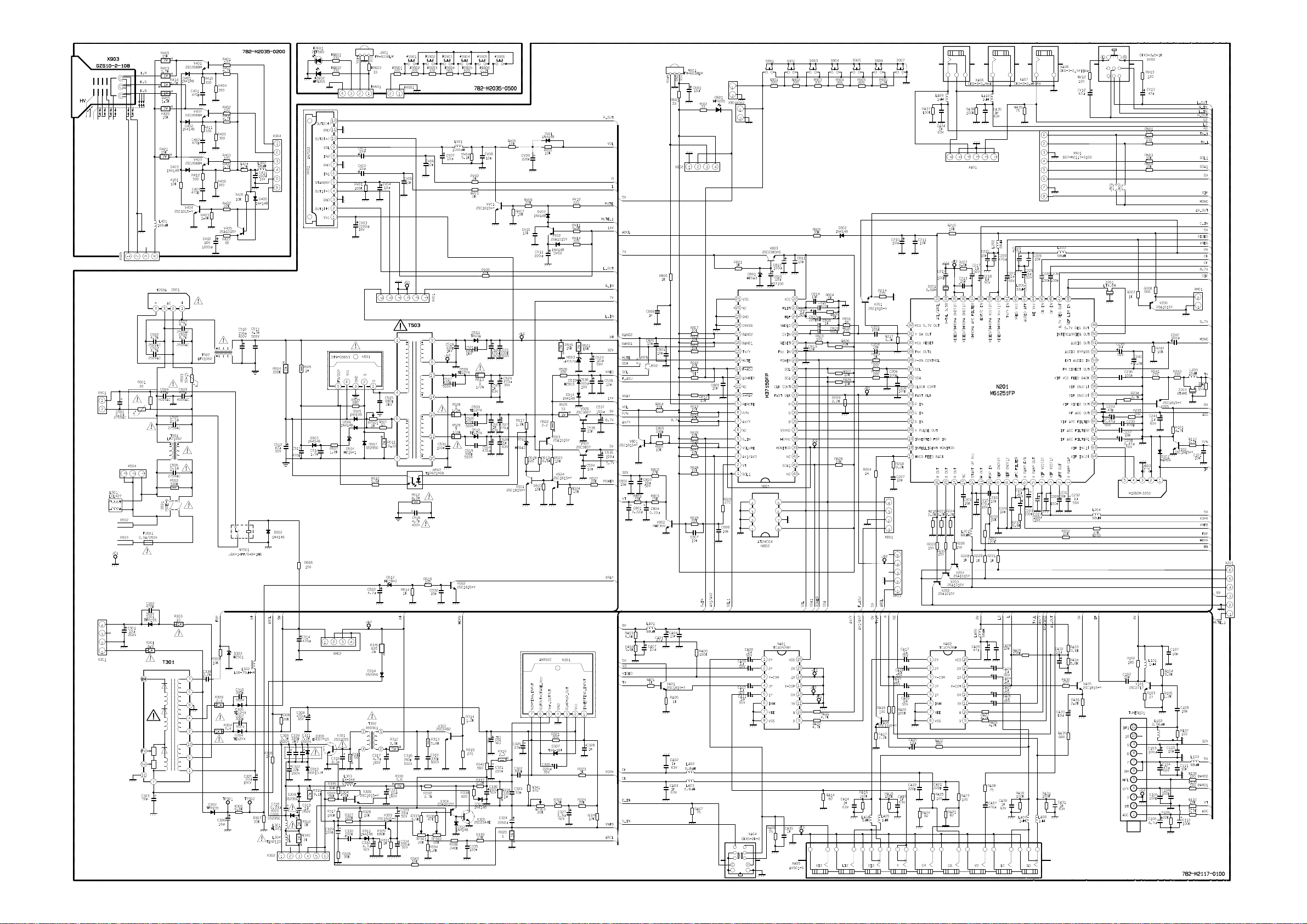
SCHEMATIC DIAGRAM………………………………………………………………..........38
CAUTION: THIS SERVICE MANUAL IS ONLY FOR PROFESSIONAL SERVICE PERSONNEL’S
REFERENCE. BEFORE SERVICING THIS CHASSIS, PLEASE READ THE
FOLLOWING NOTICE ITEMS.
Page 3

SAFETY INSTRUCTION
Before servicing and aligning this equipment, please read the following “X-RAY RADIATION
PRECAUTION” ,“SAFETY PRECAUTION” and “PRODUCT SAFETY NOTICE”.
X-RAY RADIATION PRECAUTION
1. Excessive high voltage can produce potentially hazardous X-RAY RADIATION. To avoid such
hazards, the high voltage must not be above the specified limit. The normal value of the high voltage
of this receiver is 26.5kV(20”) at zero beam current (minimum brightness) under 220V AC power
source. the high voltage must not, under any circumstances, exceed 26.5kV.
2. Each time a receiver requires servicing, the high voltage should be checked following the HIGH
VOLTAGE CHECK procedure in this manual. It is recommended the reading of the high voltage be
recorded as a part of service record. It is important to use an accurate and reliable high voltage meter.
3. This receiver is equipped with a Fail Safe (FS) circuit which prevents the receiver from producing an
excessively high voltage even if the B+ voltage increases abnormally. Each time the receiver is
serviced, the FS circuit must be checked to determine that the circuit is properly functioning,
following the FS CIRCUIT CHECK procedure in this manual.
4. The primary source of X-RAY RADIATION in this TV receiver is the picture tube. For continuous
X-RAY RADIATION protection, the replacement tube must be exactly the same type tube as specified
in the parts list.
5. Some parts in this receiver have special safety-related characteristics for X-RAY RADIATION
protection. For continuous safety, parts replacement should be undertaken only after referring to the
PRODUCT SAFETY NOTICE below.
SAFETY PRECAUTION
WARNING:
Service should not be attempted by anyone unfamiliar with the necessary precaution on this receiver. The
following are the necessary precautions to be observed before servicing this chassis.
1) Since the power supply circuit of this receiver is directly connected to the AC power line, an isolation
transformer should be used during any dynamic service to avoid possible shock hazard.
2) Always discharge the picture tube anode to the CRT conductive coating before handling the picture tube.
The picture tube is highly evacuated and if broken, glass fragments will be violently expelled. Use shatter
proof goggles and keep picture tube away from the unprotected body while handling.
3) When replacing a chassis in the cabinet, always be certain that all the protective devices are put back in
place, such as: non-metallic control knobs, insulating covers, shields, isolation resistor-capacitor network
etc.
4) When replacing parts or circuit boards, disconnect the power cord.
5) When replacing a high wattage resistor (oxiode metal film resistor) on the circuit board, keep the resistor
10mm (1/2in) away from circuit board.
6) Connection wires must be kept away from components with high voltage or high temperature.
7) If any fuse in this TV receiver is blown, replace it with the FUSE specified in the chassis parts list.
1
Page 4
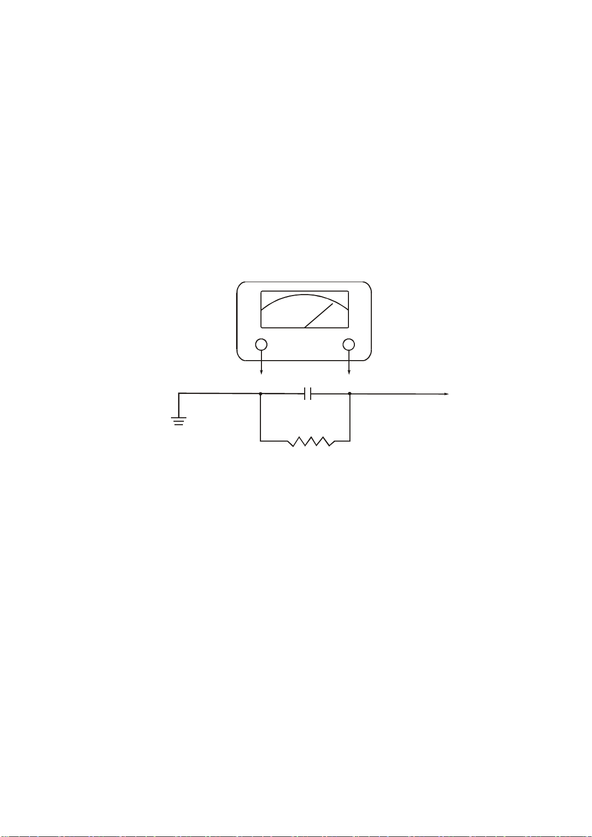
8) Before returning the set to your customer, always perform an AC leakage current check on the exposed
A
metallic parts of the cabinet, such as antennas, terminals, screwheads, metal overlays, control shafts etc. to
be sure the set is safe to operate without danger of electrical shock. Plug the AC line cord directly into a
220V AC outlet (do not use a line isolation transformer during this check). Use an AC voltmeter having
5000 ohms per volt or more sensitivity in the following manner:
Connect a 1500 ohm 10 watt resistor, paralleled by a 0.15µF, AC type capacitor, between a known good
earth ground (water pipe, conduit, etc.) and the exposed metallic parts, one at a time. Measure the AC
voltage across the combination of 1500 ohm resistor and 0. 15µF capacitor. Reverse the AC plug at the AC
outlet and repeat AC voltage measurements for each exposed metallic part. Voltage measured must not
exceed 0.3 volts RMS. This corresponds to o.2 milliamp. AC. Any value exceeding this limit constitutes a
potential shock hazard and must be corrected immediately.
C VOLTMETER
μ
0.15 FD
Good earth ground
such as a water
pipe, conduit, etc.
1500ohm
10watt
Place this probe on
each exposed
metallic part.
PRODUCT SAFETY NOTICE
Many electrical and mechanical parts in the chassis have special safety-related characteristics. These
characteristics are often passed unnoticed by a visual inspection and the X-RAY RADIATION protection
afforded by them cannot necessarily be obtained by using replacement components rated for higher wattage,
etc. Replacement parts which have these special safety characteristics are identified in this manual and its
supplement electrical components having such features are shaded on the schematic diagram and the parts list.
Before replacing any of these components, read the parts list in this manual carefully. The use of substitute
replacement parts which do not have the same characteristics as specified in the parts list may create shock,
fire, X-RAY RADIATION or other hazards.
B+ CHECK
1) Prepare the test equipment.
2) Use the DC voltameter at DC 370V position to test B+ test point, i.e. B+.
2
Page 5

3) Connect the power plug to AC 220V/50Hz, turn on the power switch, wait for normal raster, Check B+ =
110V±0.2V.
Test point B+ B1-5V B2-8V B3-10V B4-32V TH-12V TH-20V TH-200V
DC(V) 110 5 8 12 32 12 20(22) 200
INSTALLATION AND SERVICE ADJUSTMENTS
GENERAL
In the majority of cases, a color television receiver will need only slight touch – up adjustment upon
installation. Check the basic characteristics such as FS,EHV,and focus. Observe the picture for good black and
white details without objectionable color shading. If color shading is evident, demagnetize the receiver.
If color shading still persists, perform purity and convergence adjustments. This should be all that is necessary
to achieve optimum receiver perfomance.
FOCUS ADJUSTMENT
Adjust the FOCUS control (on T301) for well defined scanning lines on the picture screen.
HIGH VOLTAGE CHECK
CAUTION: These is no HIGH VOLTAGE ADJUSTMENT on this chassis. Checking should be done
following the steps below.
1. Connect an accurate high voltage meter to the second anode of the picture tube.
2. Turn on the receiver. Set the BRIGHTNESS and CONTRAST controls to minimum (zero beam current).
3. High voltage will be measured below 26.5(20”)KV.
4. Vary the BRIGHINESS control to both extremes to be sure the high voltage does not exceed the limit
under any conditions.
General instruction
1. This chassis’ EEPROM'(N801 M24C08) should copy standard data, if necessary, deal it with “factory
adjustment”. If directly use blank EEPROM, should first preset I
alignment. For factory adjustment method, refer to The appendix: factory menu.
2. If without special indication, the alignment is conducted on the below condition:
a) AC power supply 220 V/50 Hz.
b) The whole unit is preheated for more than 30 min.
3. There is built-in auto degaussing circuit, it will degauss automatically within 1second after turning on.
4. If CRT is with magnetism and affects color purity and convergence, the internal degaussing can not degauss
completely, can use degaussor to degauss externally. If color purity and convergence is still poor, then
do color purity and convergence adjustment.
2
C data, then go on other common
Alignment items and procedure
1. B+ voltage check
2. RF AGC voltage adjustment
3. Focus adjustment
4. Screen-grid voltage and white balance adjustment
5. Horizontal,vertical scan center adjustment
6. Horizontal,vertical scan amplitude adjustment
7. Pattern correction adjustment
8. The alignment flow chart see figure below.
3
Page 6
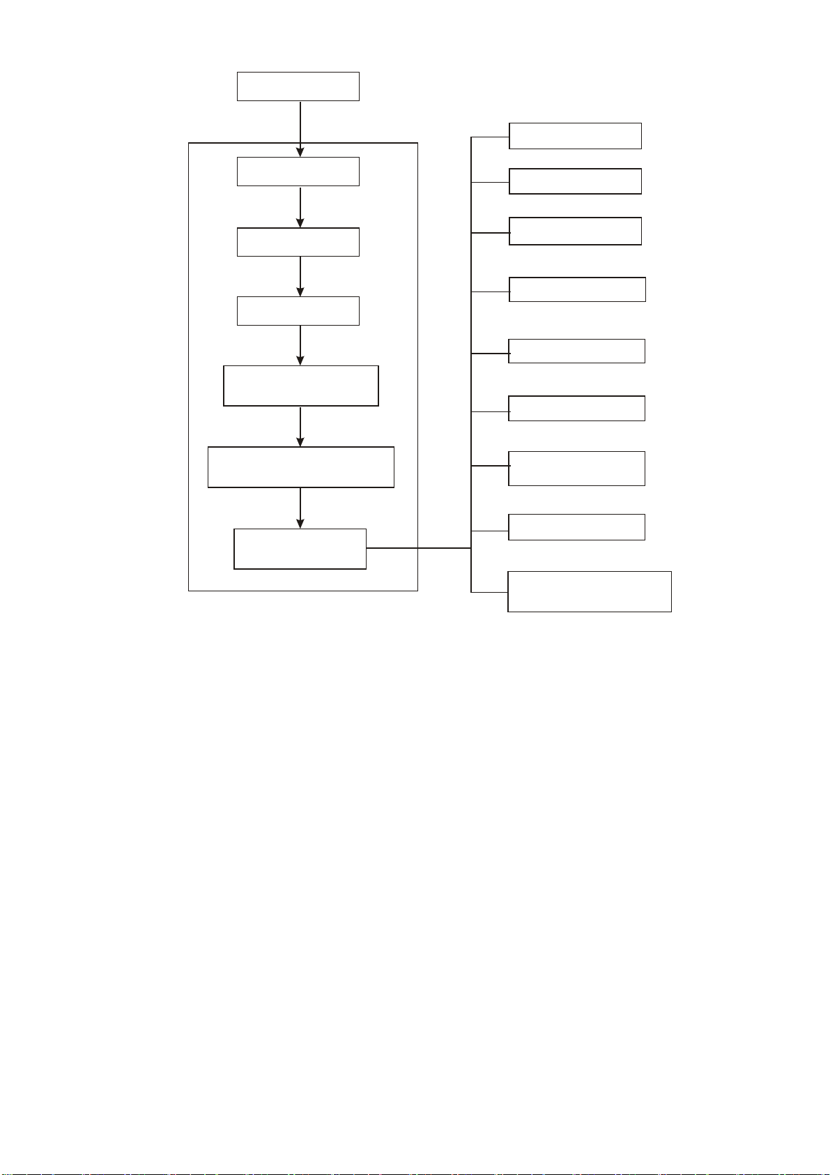
EEPROM copy
B+ check
High voltage check
X-ray protection check
RFAGC adjustment
Filament voltage check
FOCUS
Picture and sound check
Sub-brightness check
Screen-grid voltage
White balance adjustment
White balance check
Scanning amplitude center &
raster correction adjustment
Color purity
convergence check
、
Check
AV terminal check
Figure 1: Alignment flow chart
The TV set & remote
controller's function check
Factory adjustment mode
1. B+ voltage test
a) Make sure the AC power is 220 V/50 Hz
b) Connect digital voltmeter to B+ test point, receive A-7 signal, set picture control to“DYNAMIC”
state, test B+, the test voltage should be 100 V±0.5 V (21” PF), or 110V±0.5 V (14” PF AND 21”),
or 140V (25”).
2. AGC adjustment
a) Receive 60 dB split field A-7 signal.
b) Use oscilloscope or digital voltmeter to monitor test N201 pin 43 voltage (AGC output).
c) enter factory menu, select RF DELAY ADJ, by making use of [←][→] button, increase the value from low
to high until the voltage just reach 4.0 V, at this time picture noisy spot should basically disappear,
otherwise continue fine tune RF DELAY ADJ
3. Focus adjustment
3. 1 Receive A-12 signal, set user control to “DYNAMIC” state.
3. 2 Adjust FBT’s focus potentiometer, to make the screen’s B area’s focus optimum.
4. Acelerating electrode adjustment method (use A-7 signal)
4.1 Roughly adjust white balance, fix GCUT value, adjust RCUT, BCUT, RDRV, BDRV ’s value to make
4
Page 7

white balance basically normal.
4.2 Set the color to 0, contrast to 10, use oscilloscope to adjust CRT’s red gun’s waveform (see below figure),
adjust brightness to make the seventh step’s (the darkest) DC level be 180V, adjust accelerating electrode
to make the seventh step slightly light up (just can separate the seventh step and below dark field).
4.3 Fine adjust white balance (color temperature: 12000K±8MPCD X=0.270±0.008 Y=0.283±0.008 )
4.4 Set contrast,brightness,color all to 0, adjust BRTN to make A-7’s upper left 2 lattice slightly light up.
5. Horizontal, vertical scan center adjustment
NTSC(60Hz)H-center,V-center adjustment
Receive G23 signal, set user control to “DYNAMIC” state, adjust V-center V-position, H-PHASE to
make picture’s center be in accordance with screen’s center.
6. Vertical scan amplitude adjustment
NTSC(60 Hz)V-amplitude adjustment
Receive D35 signal, set user control to “DYNAMIC” state, adjust V-amplitude V-SIZE to make picture’s
upper and lower over scanning be screen size’s 8%.
0V
Fig 2: red gun waveform
180V
Checking point
1. High voltage check
1.1 Connect high voltage meter to CRT’s second anode and GND.
1.2 Receive D-8 signal, set user control to “DYNAMIC” state, the high voltage should be 29.0 kV±1 kV
(21” PF and 25”) or 25.0kV±1kV (14” PF) or 26.5kV±1kV (21”).
1.3 When brightness and contrast be set to minimum (zero beam current), the high voltage should not exceed
32 kV.
2. CRT filament voltage check
Receive D-8 signal, set picture control to “DYNAMIC” state, use effective value voltmeter to test CRT
filament voltage, the reading should be (6.3±0.3)Vrms.
3. X-ray protection check
3.1 Receive D-8 signal, set user control to “DYNAMIC” state.
3.2 Short R305(TP301,TP302),X-ray protection circuit should effect.
5
Page 8

4. Picture and sound check
4.1 Receive standard TV signal.
4.2 Making use of picture control buttons to check color,contrast,brightness,sharpness,tint’s control function.
4.3 Making use of sound control buttons to check volume control function.
5. Sub-brightness check
Receive D-8 signal, set color ,contrast,brightness all to 0, picture’s left side first grid slightly lights.
6. Color purity and convergence check(Use common regulation)
7. AV terminals ( AV IN/OUT check)
8. Other control buttons (on the set and on the remote controller) function check.
Preset the following in factory
1. Picture menu:
BRIGHTNESS 30
COLOR 30
SHARPNESS 30
TINT ±00
PICTURE
▼MORE
2. Volume preset to 30.
3. Set OSD language to English.
4. TV mode: channel position number CABLE 3.
CONTRAST 60
PERSONAL
MODE
Factory menu
1. Enter into factory menu to operate.
1.1 Press factory button ,enter into factory menu.
1.2 Use CH+/CH- button to select the menu, use VOL+/VOL- button to enter the function menu.
1.3 In factory menu status, press MENU button to exit.
2. Factory menu contents
6
Page 9

Appendix 1 FACTORY MENU
FACTORY MENU
1:VDJ ADJ
1. VIF VCO AUTO ADJ OFF VIF VCO auto adjustment
2. RF DELAY ADJ TUNER AGC adjustment
3. S-TRAP ADJ S-TRAP auto adjustment
2: RASTER ADJ
1. V-POSITION
Vertical position adjustment(PAL)
2. V-SIZE Vertical size adjustment
3. H-POSITION Horizontal position adjustment
4. WHITE BACK
5. VS-CORRECTION Vertical S-adjustment
6. V-LINEARITY Vertical linear adjustment
7. H-POSITION(N)
8. V-SIZE(N)
9. V-SHIFT(N)
10. VS-CORRECTION(N)
11. V-LINEARITY(N)
Horizontal position adjustment
Vertical size adjustment
Vertical position adjustment
Vertical S-adjustment
Vertical linear adjustment
3: CRT ADJ
1. CUT OFF-R TV white balance adjustment
2. CUT OFF-G
3. CUT OFF-B
4. DRIVE R
5. DRIVE B
6. YUV)CUT OFF-R
7. YUV)CUT OFF-G
8.(YUV)CUT OFF-B
9. YUV)DRIVE-R
10.(YUV)DRIVE-B
YUV white balance adjustment
4: PICTURE ADJ
1. SUB BRIGHTNESS Sub-brightness adjustment
2. SUB CONTRAST Sub-contrast adjustment
5: USER MENU RESET OFF User menu presetting
6: SERVICE MENU
1. H VCO ADJ Horizontal VCO auto adjustment
2. TRAP FINE ADJ Color trap fine adjustment
3. SUB TINT TV sub tint
4. SUB TINT AV AV sub tint
5. SUB TINT YUV YUV sub tint
6. SUB COLOR Color adjustment
7. C ANGLE95
8. TAKE OFF Color BPF/TAKE OFF on/off
9. OSD LEVEL OSD level on/off
10. Y-DL Brightness delaying time
11. Y-DL SECAM
12. SECAM KILLER
7
Page 10

13. SECAM BGP
14. VIDEO OUTGAIN Demodulation output range adjustment
15. OM DET Over modified detecting on/off
16. S-SLICE DOWN Sync detecting slice stage
17. AUTO SLICE DN Auto detecting on/off
18. V SYNC DET Vertical sync detecting
19. V-1 WINDOW
20. AFC1 GAIN UP H AFC1gain
21. AFC2 GAIN DOWNN H AFC2 gain
22. ABCL Brightness/contrast auto control
23. ABCL GAIN Brightness/contrast auto control gain
24. GAMMA
25. BLACK ST OFF Black level delay on/off
26. BLACK ST ADJ
27. BLACK ST GAIN
28. VIF FREQ VIF selecting
29. VDL ADJ
30. UDL ADJ
31. IC SELECTION
32. OP PAL-M/N
33. OP AV-SUSTEM AV mode
34. AUDIO ATT Volume output control
35. MONITORING
36. EEPROM OPTION EEPROM selecting
37. POW-ON SEARCH Power-on search selecting
38. OSD H-POSITION OSD horizontal position adjustment
39. EEP ADJ EEPROM modifying
40. PIC-DYNAMIC Dynamic scalar selecting
41. PIC-STANDARD Standard scalar selecting
42. PIC-SOFT Soft scalar selecting
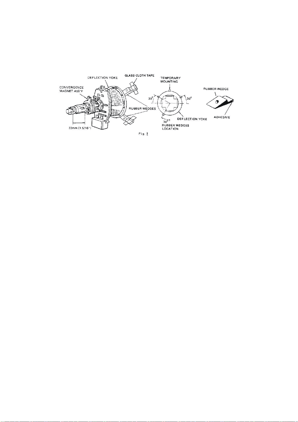
CONVERGENCE MAGNET ASSEMBLY POSITIONING
Convergence magnet assembly and rubber wedges need mechanical positioning. Refer to below figure 1.
COLOR PURITY ADJUSTMENT
NOTE: Before attempting any purity adjustment, the receiver should be operated for at least fifteen minutes.
1. Demagnetize the picture tube and cabinet using a degaussing coil.
2. Set the CONTRAST and BRIGHTNESS controls to the maximum.
3. Receive PM5515 monochromatic signal (such as G) to provide a green raster on the screen.
4. Loosen the clamp screw holding the yoke, and slide the yoke backward to provide vertical green belt
(zone) in the picture screen.
5. Remove the Rubber Wedges.
6. Rotate and spread the tabs of the purity magnet around the neck of the picture tube until the green
belt is in the center of the screen. At the same time, center the raster vertically by adjusting the
magnet.
7. Move the yoke slowly forward or backward until a uniform green screen is obtained. Tighten the
clamp screw of the yoke temporarily.
8
Page 11
8. Check the purity of the red and blue raster.
9. Obtain a white raster, referring to “CRT WHITE BALANCE ADJUSTMENT”.
10. Proceed with convergence adjustment.
FIG.3
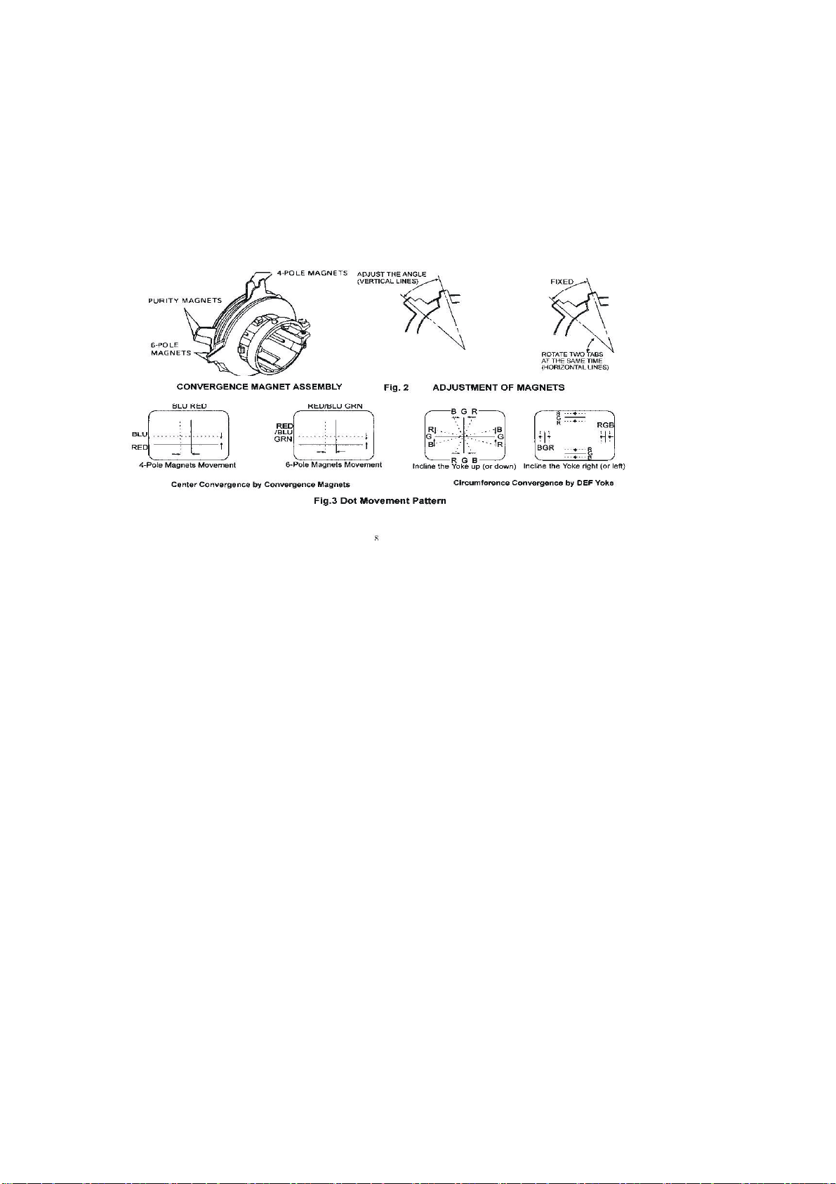
CONVERGENCE ADJUSTMENT
NOTE: Before attempting any convergence adjustments, the receiver should be operated for at least fifteen
minutes.
CENTER CONVERGENCE ADJUSTMENT
1. Receive crosshatch pattern with a color bar signal generator.
2. Adjust the BRIGHTNESS and CONTRAST controls for well defined pattern.
3. Adjust two tabs of the 4-Pole Magnets to change the angle between them (see figure 4) and superimpose red
and blue vertical lines in the center area of the picture screen. (see figure 5)
4. Turn the both tabs at the same time keeping the constant angle to superimpose red and blue horizontal lines
at the center of the screen.(see figure 5)
5. Adjust two tabs of 6-Pole Magnets to superimpose red/blue line with green one. Adjusting the angle affects
the vertical lines and rotating both magnets affects the horizontal lines.
6. Repeat adjustments 3,4,5, keeping in mind red, green and blue movement, because 4-Pole Magnets and
6-Pole Magnets interact and make dot movement complex.
CIRCUMFERENCE CONVERGENCE ADJUSTMENT
1. Loosen the clamping screw of deflection yoke to allow the yoke to tilt.
2. Put a wedge as shown in figure 1 temporarily. (Do not remove cover paper on adhesive part of the wedge.)
3.Tilt front of the deflection yoke up or down to obtain better convergence in circumference. (See figure 5).
Push the mounted wedge into the space between the picture tube and the yoke to hold the yoke temporarily.
4. Put other wedge into bottom space and remove cover paper to stick.
5. Tilt front of the yoke right or left to obtain better convergence in circumference (see figure 5)
9
Page 12
6. Keep the yoke position and put another wedge in either upper space. Remove cover paper and stick the
wedge on the picture tube to fix the yoke.
7. Detach the temporarily mounted wedge and put it in another upper space. Stick it on the picture tube to fix
the yoke.
8. After fixing three wedges, recheck overall convergence. Tighten the screw firmly to fix the yoke tightly in
place.
9. Stick three adhesive tapes on wedges as shown in figure 3.
Fig5. Dot Movement Pattern
10
Page 13

WIRING DIAGRAM
XM03
XM01
VM PCB
+
-
782-29FA0-6400
XM02
SPEAKER
+
-
+- +-
#XA03
XA01
XM01
X201
AV PCB
XV04
782-M2035-2900
XV03
XV01
X901
X902
MAIN PCB
XM03
782-M2127-010D
X601
BUTTON PCB
782-M2035-0500
STANDBY PCB
782-13Y90-0500
X602
X902
X502
A2
A1
XM02
X302
X301
DRIVER
COIL
DEGASSING
HORZIONTA L
TRANSFORM ER
FOCUS
SCREEN
X403
X402
X401
CRT PCB
11
CRT
782-M2035-0200
Page 14

12
Page 15
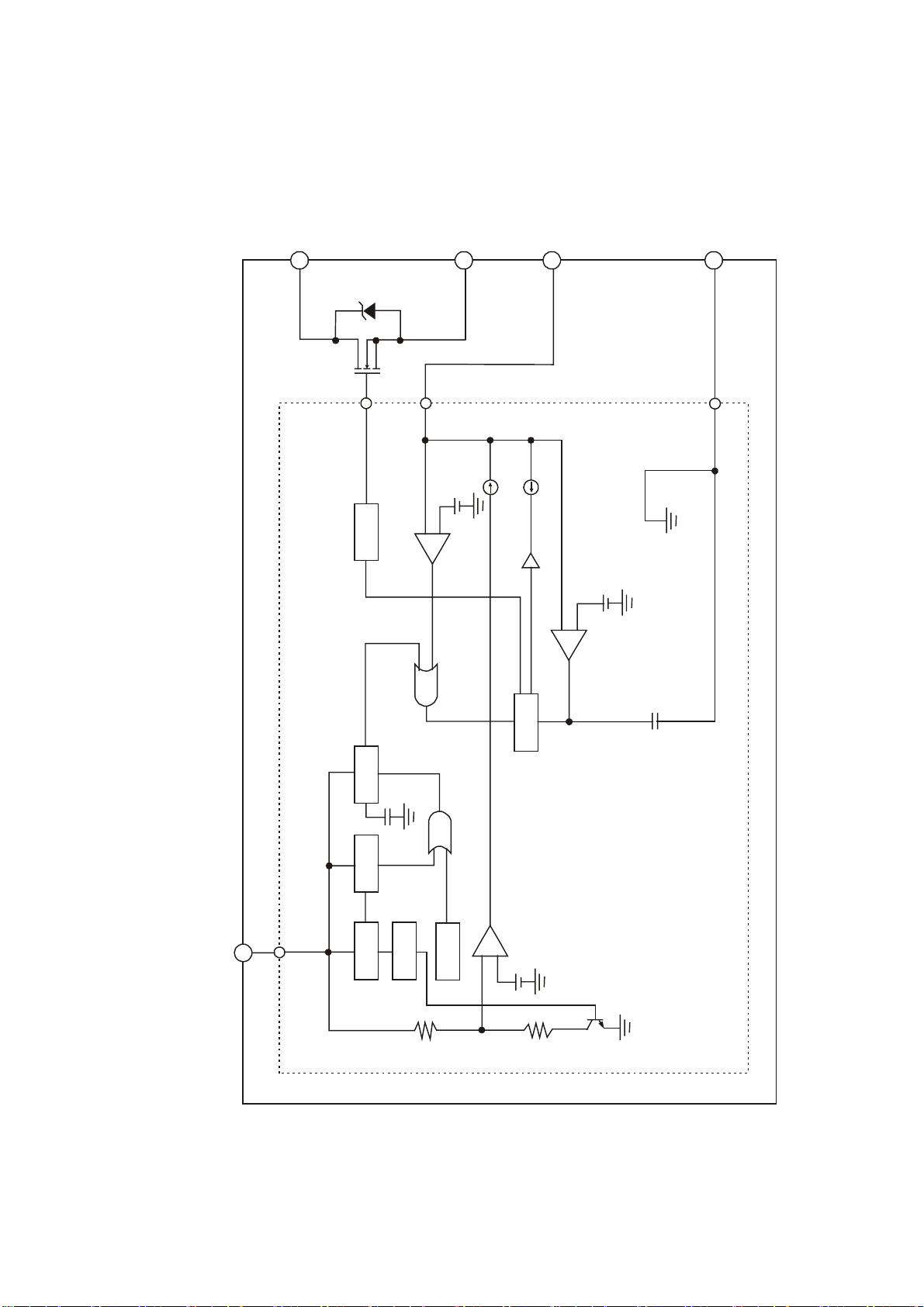
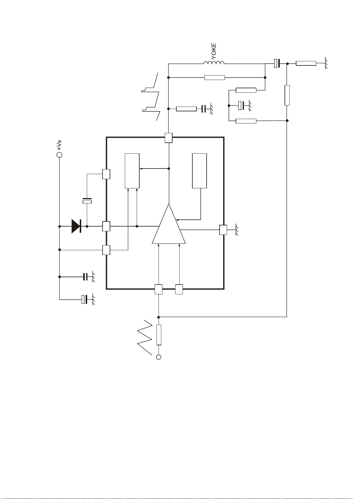
IC BLOCK DIAGRAM
1D
S
2
VIN1
+
-
O.C.P/F.B
5
VIN2
GND
3
-
+
STR-G5653
O.S.C
Vin
4
START O.V.P LATCH DRIVE
REG
+
-
T. S . D
ERROR AMP
13
Page 16

PE
26
10K
10K
(T a )
10
3.3
+
+
SDA/SAPID
SCL/STID
24
27
2.2
32
+
2
3
(T a )
3.3
0.1
5
(±10%)
0.022
+
6
4
AN 5832SA
S pectral
Wide B and
Filte r
180K
2
IC
D ecoder
Filte r
10% Tantalum capacito r
(T a )
28293015251917182321
Spectral
Wide B and
Wide Band
RMS Det
Expand
2.2
Lout Rout
2.2
+
GND
AGC
Matrix
& M ode S W
O ffs e t
C ancel
Offs e t
C ancel
L-R
L+R
Filte r
75 s
De-Em ph
Filte r
SAP out
5V
VCC
Pilot D et
+
0.33
PLL
Pilot
C ancel
SAP
RM S Det
Spectral
Expand
Dbx
De-Em ph
(L -R )/S A P
Switc h
Filte r
0.1
13
Demod
Noise
Det
0.1
3.3K
SIF
Base B and
0.22
Input
Input
+++++
2.2 2.2 2.22.2
1000P
+
4.7
SIF
22
Input
Demod
4.7
14
Offset
Cancel
Stereo
Filte r
VCA
SIF/BB
SW
8
7
AGC
2
IC /PA R A
SAP
SAP
Det
Filte r
9
MODE
10
FO M O
Noise
Filte r
11
MUTE
14
0.033
12
SIF/BB
M ode C ontrol S W
Page 17

AN7522N
11 12
10
15
3 4 5 6 7 8 9
2
1
Vcc GND
Page 18
5
362
Thermal
Flyback
Generator
Protection
4
Power
Amplifier
-
+
TEA8172
1
7
16
Page 19

DY
OUT P UT
B
R
RIN
GIN
FAST BLK
SCL
AUDIO
OUT
SDA
G
BIN
VERTICAL
8V
V.OUT
V.PULS E
OUT
6
51
26
43
ATT
BUS
AF
FM
5.7V reg RESET
I/F
AUDIO SW
FM
AMP
MUTE
DET
R EXT
INP UT
LIMITE R
HPF
POWER ON
CONTROL
P-ON-ON
(WH ITE )
US/JPN
VCO
ADJ
DET
VIDEO
ATT
EXT AUDIO IN
DIRECTOUT
5V
Vcc5V
Vcc8V
11V
DD
MCU V
5V
VIDEO
OUT
1Vp-p
53
54
52
56
VIFGND
57
3
VIFVcc
4
LIMITE R
IN
48
INTER
CARRIER
OUT
502849
fromMC U
8.7V 5.7V
47
30
RESET
to MCU
32
8.7V
4258556061
VIFVCOADJ
G EXT
14
15
HV
CLAMP
B EXT
INP UT
INP UT
B
AMP
DRIVE
DRIVE
R
BRIGHT
BRIGHT
RGB
MA TR IX
BLUE BACK
CONTRA ST
DET
APC
CONTRA ST
COLOR
DET
LOCK
REF
FIL TE R
ADJ
DET
21
22
23
24
27
5
16
SERVICE SW
BLK
VERTICAL
B
G
R
CUT OFF
TRI G
V SYNC
EQ
SEP
SYNC
SYNC
SLICE
DEMODULA TOR
YUV
SW
1
20
V.RAMP
COUNT DOWN
ELIMINATE
KILLERB
18
Intelli gent
Monitoring
H-PHASE
V.SIZE
V.SHIFT
HORIZONTAL
VCOINB
BGP
HVCO ADJ
ANGLE
TIN T
DET
KILLER
TAKE OFF
BPF
CHROMA
Intelli gent Monitoring
AFC2
HSTOP
COUNT DOWN
HVCO
GEN
AFCGAIN
VCO
ADJ
TIN T
BASE BAND
TIN T
CLK CONT
BASEBAND
DET
ACC
ACC
HPF
DEF
Vcc
12
13
NC
H. OUTPUT
11
H
COINCI.
HCOINB
DEF
GND
89
44
Hi V cc
AFC1
7
10
INV
17 19
45 46
29
VCXO
3.58MH z
40 34
VIDEO/CHROMA
Vcc
37 39
APC
DET
CHROMA
36
35
VIDEO/CHROMA
GND
25
38
8V
FB P
IN
FB P
INV
OUT
Cr IN
Cb IN
fsc
OUT
5V
CLOCK
CONTROL
1Vp -p
EXTIN /C IN
IF AGC VCO
62
VIF
AMP
RF AGC
DELAY ADJ
59
OUT
RF AGC
64
63
IN
VIF
SAW
IF IN
MUTE
AFTOUTDEFEAT
MUTE
AFT
2
AFT
OUT
VIDEO
VIDEO
CLAMP
GA MMA
GA MMA
BLACK STRETCH
BLACK
STRETCH
33
ACL/ABCL
17
SHARPNESS
DL
TIME
DL
SW
FIN E
TRA P
TON E
VIDEO
DELAY
CHROMA
TRA P
x2
F.TR A P
YSW
LPF
LPF
31
Y-SWOUT
41
TV IN / Y IN
1Vp -p
Page 20

PART LIST
PART# DESCRIPTION LOCA.NO.
100-M20190-11 TS2019
100-M20190-01 M2019
123-30001-04 TWIST WIRE
384-40316-Q0 SPEAKER ST511-01
477-12105-00 DEGAUSS COIL DX-56-2 !
655-21201-128 (2-PINS) LEAD WITH HOUSING
808-1D550-01
665-62101-01 (6-PINS) LEAD WITH HOUSING
700-60127-00 LED COLUMN
741-10001-02 WIRE FIXED BLADE
742-30005-09 LINE TIE
742-30006-09 GRADING TIE
742-30029-00 POWER CORD CLASPER
742-30032-00 TIE
742-30038-00 TIE
776-37112-40 UL1015 24# 370mm BLACK
808-70239-00 EVA GLUE 150X50X1
838-10012-00 BRAIDED WIARE SPRING
851-23010-14 SCREW SJ2824 ST3X10C-Y
851-23012-14 SCREW SJ2824 ST3X12C-Y
851-24012-14 SCREW SJ2824 ST4X12C-Y
851-24020-11 SCREW SJ2824 ST4X20C-D.Zn
851-24020-14 SCREW SJ2824 ST4X20C-Y
851-23008-11 SCREW SJ2824 ST3X8C-D.Zn
851-23008-11 SCREW SJ2824 ST3X8C-D.Zn
851-53012-11 SCREW SJ2825 ST3X12C-D.Zn
855-96030-11 COMPOSE SCREW ST6X30C-D.Zn
857-10002-09 COTTON FLANNEL
857-10004-00 COTTON FLANNEL
868-20007-00 SLEEVE
868-20140-00A CRTCUSHION
868-20142-00 RUBBER WASHER (δ1.5)
877-50369-0E0A TOUCH SWITCH KEY ( SILVER GREY GR10)
776-99203-01 UL1185 26# 990mm BROWN
887-21135-00 CLASPE RPALSTIC BAG 230X330X0.1
881-60085 BLANK WARNING LABEL
887-20044-01 POWER CORD COVER
887-20171-00 PALSTIC BAG 70-500-0.06
894-30050-11 WASHER GB97.1-85-5-140Hv-D.Zn
100-J21190-02FD ASSEMBLY ACCESSORY RATION
335-2112N-00U CRT54SX538Y22-DC01 THIN !
780-10761J040C BACK CABINET ( MOLD GREY )
611-30286J0E1 FRONT CABINET ASS'Y (HIPS V0 SILVER GREY
INTERFACE SPACE PLATE (SILK-SCREEN )
18
Page 21

863-80664-00
863-80665-00
886-31047-00
POLY FOAM (TOP )( SMALL )
POLY FOAM (BOTTOM )( SMALL )
CARTON BOX ( BLANK ) SMALL
887-21096-P0 PE/PEARL COTTONPALSTIC BAG 1100X1000
488-10012-00 BATTERY 7#( made in china
604-M20196-00 OWNER'S MANUAL(PRIMA AMERICA )
880-10589-A1 FRONT LOGO (PRIMA SILVERY GREY 10C 21"
880-10205-757 BACK PLATE (TS2019,PRIMA)
881-63016-00A
POWER SYMBOL LABEL (T2751)
881-63633-00 UPCBAR CODE LABEL (69020752019)
881-80665-00
REGISTER CARD (PRIMA AMERICA )
881-80679-00 SERVICE CARD ( 20-24 CRT)
808-1B550-01
INTERFACE SPACE PLATE (SILK-SCREEN )
384-40308-40 SPEAKER ST511-02
655-61201-161
877-50369-01A
(6-PINS) LEAD WITH HOUSING
TOUCH SWITCH KEY ( SILVERY WHITE 03)
881-61884-00 CSA WARNING LABEL
881-63648-00 BACK PLATE LABEL
851-23010-14 SCREW SJ2824 ST3X10C-Y
881-63667-00 WARNING LABEL
886-31047-25 CARTON BOX (TS2019,PRIMA)
611-30286J0H1 FRONT CABINET ASS'Y (HIPS V0 SILVER WHITE 03
301-AM1435-040C RC-A04-0CREMOTE CONTROL UNIT (PRIMA )
667-M2019-01A MAIN PCB ASS'Y
667-M2019-01A\
340-10039-20
MAIN PCB ASS'Y (MANUAL INSERTION )
LED HFR205 (RED )
352-69380-00 IC HRM138BB3000 (M) N601
360-10070-00 TACT SWITCH EVQPC105K S902
360-10070-00 TACT SWITCH EVQPC105K S903
360-10070-00 TACT SWITCH EVQPC105K S904
360-10070-00 TACT SWITCH EVQPC105K S905
360-10070-00 TACT SWITCH EVQPC105K S906
360-10070-00 TACT SWITCH EVQPC105K S907
364-11205-00 EARPHONE JACK 3F27K XV02
364-92201-00
AV JACK CKG-3-2 ( WHITE )
XA07
364-92202-00 AV JACK CKG-3-2( YELLOW ) XA08
364-92203-00 AV JACK CKG-3-3 (RED ) XA06
459-8122K-00 CERAMIC CAPACITOR DE0707B221K2K C339
462-85433-H0 POLYESTER CAPACITOR CBB21-400V-0.33uF-J C315
462-88239-H0 POLYESTER CAPACITOR CBB81-1600V-3900pF-J C309
462-88247-H0 POLYESTER CAPACITOR CBB81-1600V-4700PF-J C311
464-6D647-M0 ELECTROLYTIC CAPACITOR CD110-16V-47uF-M C601
464-6D647-M0 ELECTROLYTIC CAPACITOR CD110-16V-47uF-M CV12
D601
Page 22

467-1C133-H0 CARBON RESISTOR 1/6W-330Ω-J R602
467-1D112-H0 CARBON RESISTOR RT14-1/4W-120Ω-J RV12
467-1D112-H0 CARBON RESISTOR RT14-1/4W-120Ω-J RV13
467-4FA33-H0 FUSIBLE RESISTOR 1W-3.3Ω-JL R301
467-6F002-H0 WIRE ROUND RESISTOR RX21-1-2Ω-J R320
470-00272-00U SWITCHING TRANSFORMERSR3601B ! T503
477-00083-00 LINERITY COIL LX221 L301
477-30019-00 VARIABLE COIL TLN2120B L304
667-M2035-01\
MAIN PCB ASS'Y (MANUAL INSERTION )
329-53601-00 CRYSTAL JA25A 3.579545MHZ G201
340-00010-00 DIODE S5295G D505
340-00291-00 DIODE TEU2YX D304
340-00291-00 DIODE TEU2YX D305
340-00291-00 DIODE TEU2YX D508
340-00291-00 DIODE TEU2YX D509
340-00291-00 DIODE TEU2YX D510
471-1015H-00 PEAKING COIL EL0606SKI-150J L205
340-00292-00 DIODE TRU3A D511
340-80022-00 RECTIFIER T2SB60 D501
343-23830-60 TRANSISTOR 2SC2383-0 V803
343-24820-00 TRANSISTOR 2SC2482 V302
343-27170-00 TRANSISTOR 2SC2717 V101
343-01800-00 TRANSISTOR KSE180 TO-126 V505
343-01800-00 TRANSISTOR KSE180 TO-126 V506
352-05740-00 IC uPC574 (D) N503
352-06210-70 IC TLP621-GB(UL) (O)! N502
352-24040-50 IC AT24C04 N802
353-37150-80 SMD ICM37150M8-096FP (D) N801
352-40520-60 IC TC4052BP (M) NA02
352-40520-60 IC TC4052BP (M) NA01
352-61251-70 IC M61251AFP (M) N201
364-32101-00 2-PINS CONNECTORS TJC3-02A X901
364-32101-00 2-PINS CONNECTORS TJC3-02A X902
364-32108-00 2-PINS CONNECTORS TJC1-2A X501
364-34101-00 4-PINS CONNECTORS TJC3-04A X602
364-36101-00 6-PINS CONNECTORS TJC3-06A XV01
364-36101-00 6-PINS CONNECTORS TJC3-06A XA01
364-36102-00 6-PINS CONNECTORS TJC2-6A X302
364-77511-00 FUSE HOLDER FU501
364-77511-00 FUSE HOLDER
364-91202-00 S-VIDEO TERMINAL CKX5-2K-2 XA04
364-98205-00 AV JACK AV901-6 XA05
457-12019-90 RELAY JQX-14FF-012-1HS ! RY501
458-07009-00 SAW FILTER M1859M Z202
459-B147M-20 CERAMIC CAPACITOR ECK-DNS471MBX ! C504
Page 23

459-B147M-20 CERAMIC CAPACITOR ECK-DNS471MBX ! C509
459-B222M-20 CERAMIC CAPACITOR ECK-DNS222MEX ! C516
459-B247R-00 CERAMIC CAPACITOR DE0807F472ZAC250V ! C502
459-B247R-00 CERAMIC CAPACITOR DE0807F472ZAC250V ! C503
459-B247R-00 CERAMIC CAPACITOR DE0807F472ZAC250V ! C507
459-B247R-00 CERAMIC CAPACITOR DE0807F472ZAC250V ! C508
459-6310R-00 CERAMIC CAPACITOR DE1510E103Z1K C511
459-8168K-00 CERAMIC CAPACITOR DE0707B681K2K C515
462-B0510-H0 POLYESTER CAPACITOR CL21X-50V-1uF-J C232
462-2B410-M0V POLYESTER CAPACITOR 250VAC-0.1uF-M ! C501
462-2B410-M0V POLYESTER CAPACITOR 250VAC-0.1uF-M ! C505
462-2B410-M0V POLYESTER CAPACITOR 250VAC-0.1uF-M ! C506
464-04747-M0R ELECTROLYTIC CAPACITOR 200USP470MA35 C526
464-04747-M0R ELECTROLYTIC CAPACITOR 200USP470MA35 C510
464-60647-M0 ELECTROLYTIC CAPACITOR CD110-50V-47uF-M C103
464-6D747-M0 ELECTROLYTIC CAPACITOR CD110-16V-470uF-M C220
464-6D747-M0 ELECTROLYTIC CAPACITOR CD110-16V-470uF-M C314
464-6D822-M0 ELECTROLYTIC CAPACITOR CD110-16V-2200uF-M CV03
467-2F115-H0 METAL RESISTOR 1W-150Ω-JL R318
464-6E747-M0 ELECTROLYTIC CAPACITOR CD110-25V-470uF-M C524
464-6E747-M0 ELECTROLYTIC CAPACITOR CD110-25V-470uF-M C527
464-6E822-M0 ELECTROLYTIC CAPACITOR CD110-25V-2200uF-M C324
464-6F747-M0 ELECTROLYTIC CAPACITOR CD110-35V-470uF-M C308
464-6F747-M0 ELECTROLYTIC CAPACITOR CD110-35V-470uF-M C529
464-60510-M0 ELECTROLYTIC CAPACITOR CD110-50V-1uF-M C235
464-60510-M0 ELECTROLYTIC CAPACITOR CD110-50V-1uF-M C815
464-62622-M0 ELECTROLYTIC CAPACITOR CD288-160V-22uF-M C305
776-15102-00 UL1007 24# 150mm BLACK JG1-JG2
464-65610-M0 ELECTROLYTIC CAPACITOR CD288-250V-10uF-M C301
467-20239-HB METAL RESISTOR RYG2-5W-3.9K-J-A R312
467-1C075-H0 CARBON RESISTOR 1/6W-75Ω-J RA07
467-1C127-H0 CARBON RESISTOR 1/6W-270Ω-J R315
464-60422-M0 ELECTROLYTIC CAPACITOR CD110-50V-0.22uF-M C238
467-2EA22-H0 METAL RESISTOR 1/2W-2.2Ω-JL R319
467-2EA22-H0 METAL RESISTOR 1/2W-2.2Ω-JL R522
467-2G315-H0 METAL RESISTOR 2W-15kΩ-JL R516
467-2G315-H0 METAL RESISTOR 2W-15kΩ-JL R521
467-2E256-H0 METAL RESISTOR 1/2W-5.6kΩ-JL R313
467-6FA15-H0 WIRE ROUND RESISTOR RX21-1-1.5Ω-J R320
467-2F033-H0 METAL RESISTOR 1W-33Ω-JL R525
471-1068H-00 PEAKING COIL EL0606SKI-680J LA01
467-2F220-H0 METAL RESISTOR 1W-2KΩ-JL R310
467-2F220-H0 METAL RESISTOR 1W-2KΩ-JL R342
467-2GB15-H0 METAL RESISTOR 2W-0.15Ω-JL R511
471-2210K-10 PEAKING COIL LGA0410-1000uH-K LV01
Page 24

776-22151-00 UL1672 22# 220mm BLACK JF1-JF3
467-2G422-H0 METAL RESISTOR 2W-220K-JL R504
467-4F001-H0 FUSIBLE RESISTOR 1W-1Ω-JL R304
467-4FA27-H0 FUSIBLE RESISTOR 1W-2.7Ω-JL R309
467-4FA39-H0 FUSIBLE RESISTOR 1W-3.9Ω-JL R301
467-4E001-H0 FUSIBLE RESISTOR 1/2W-1Ω-JL R528
467-4E001-H0 FUSIBLE RESISTOR 1/2W-1Ω-JL R529
467-4F001-H0 FUSIBLE RESISTOR 1W-1Ω-JL R303
467-8E433-H0 SOLID RESISTOR 1/2W-330kΩ-JL ! R502
467-8E582-H0A SOLID RESISTOR 1/2W-8.2MΩ-J ! R512
468-01108-00 POTENTIOMETER GVA061-100Ω±20% RP501
468-32507-00 POTENTIOMETER EVND8A-A03-B53 RP303
469-10023-00 THERMISTOR 96708 (9Ω) R501
469-40004-00 THERMISTOR 5D2-14LC ! R503
470-00295-00 SWITCHING TRANSFORMERSR4038B ! T503
459-2410R-00 CERAMIC CAPACITOR DD308-63F104Z50 C245
459-2410R-00 CERAMIC CAPACITOR DD308-63F104Z50 C246
471-1068H-00 PEAKING COIL EL0606SKI-680J LA06
471-2A82K-00 PEAKING COIL SPT0305-8R2K-5 LA02
471-2A82K-00 PEAKING COIL SPT0305-8R2K-5 LA03
471-2B56K-00 PEAKING COIL SPT0305-R56K-5 L101
471-2001K-A0 PEAKING COIL SP0203-1uH-K LA04
471-2001K-A0 PEAKING COIL SP0203-1uH-K LA05
471-2001K-A0 PEAKING COIL SP0203-1uH-K LA07
471-2001K-A0 PEAKING COIL SP0203-1uH-K LA08
471-2001K-A0 PEAKING COIL SP0203-1uH-K LA09
471-2001K-A0 PEAKING COIL SP0203-1uH-K LA10
569-13141-90 FUSE 50T T3.15A/250V UL ! FU501
472-10001-00 HORIZONTAL DRIVE TRANSFORMER XR0961 T302
475-15451-00 CERAMIC FILTER LT4.5MH Z201
475-25451-00
CERAMIC TRAP FILTER XT4.5MB
Z203
477-00065-00 LINERITY COIL HL1830H-X13 L301
477-20028-00 POWER FILTER LF21065 ! T501
477-20028-00 POWER FILTER LF21065 ! T502
477-30026-00 VARIABLE COIL TLN2130 L304
477-40031-00 FIXED COIL LG750 L302
491-702D0-02 POWER CORD UL !
590-40707-00 TUNER 115-B-8035AZ TUNER
666-13501-00 FERRITE BEAD TBL-P# 2122651A D508
666-13501-00 FERRITE BEAD TBL-P# 2122651A D509
666-13501-00 FERRITE BEAD TBL-P# 2122651A D510
666-13501-00 FERRITE BEAD TBL-P# 2122651A D511
666-13501-00 FERRITE BEAD TBL-P# 2122651A V301
666-13501-00 FERRITE BEAD TBL-P# 2122651A N501
666-13501-00 FERRITE BEAD TBL-P# 2122651A
Page 25

775-10054-00 SOLDERING BLADE X502
775-10054-00 SOLDERING BLADE X503
775-60044-00 SOCKET PIN RT-01T-1.3B TP301
775-60044-00 SOCKET PIN RT-01T-1.3B TP302
776-40151-40 UL1672 22# 400mm BLACK JC1-JC2
464-6D810-M0 ELECTROLYTIC CAPACITOR CD110-16V-1000uF-M C537
464-6D610-M0 ELECTROLYTIC CAPACITOR CD110-16V-10uF-M C534
464-6D610-M0 ELECTROLYTIC CAPACITOR CD110-16V-10uF-M C535
998 JUMPER WIRE L206
459-5210K-00 CERAMIC CAPACITOR RQC07B102K-H46CA C531
459-6133K-00 CERAMIC CAPACITOR DE0405B331K1K C518
459-6133K-00 CERAMIC CAPACITOR DE0405B331K1K C521
464-60647-M0 ELECTROLYTIC CAPACITOR CD110-50V-47uF-M C512
464-6C722-M0 ELECTROLYTIC CAPACITOR CD110-10V-220uF-M C538
464-6D810-M0 ELECTROLYTIC CAPACITOR CD110-16V-1000uF-M C215
464-6D810-M0 ELECTROLYTIC CAPACITOR CD110-16V-1000uF-M C223
464-6E610-M0 ELECTROLYTIC CAPACITOR CD110-25V-10uF-M C106
467-4EB33-H0 FUSIBLE RESISTOR 1/2W-0.33Ω-JL R513
464-6F810-M0 ELECTROLYTIC CAPACITOR CD110-35V-1000uF-M C320
998 JUMPER WIRE JS01
998 JUMPER WIRE JS02
998 JUMPER WIRE C338
459-2182H-90 CERAMIC CAPACITOR CC1-12C-SL-63V-821J C816
998 JUMPER WIRE J357
998 JUMPER WIRE J347
472-24213-00 FBT BSC24-3031*UL! T301
881-60074-00 HIGH VOLTAGE WARNING LABEL
681-40003-00 OK LABEL
742-30005-09 LINE TIE
467-1C510-H0 CARBON RESISTOR 1/6W-1M-J R204
742-30005-09 LINE TIE
343-18030-80 TRANSISTOR ST1803DHI V301
352-56230-10 IC STR-G5623A (M) N501
352-75220-00 IC AN7522N (M) NV01
352-93020-10 IC STV9302A (M) N301
462-53439-H0 POLYESTER CAPACITOR CBB12-200V-0.39uF-J C315
462-88247-H0 POLYESTER CAPACITOR CBB81-1600V-4700PF-J C309
462-88268-H0 POLYESTER CAPACITOR CBB81-1600V-6800pF-J C311
706-T3003-01 HEAT SINK NV01
706-20203-00 HEAT SINK V301
706-46006-01 HEAT SINK N301
706-64002-01 HEAT SINK N501
851-13006-52 SCREW P(+) T3X6 NV01
851-13006-52 SCREW P(+) T3X6
851-13008-56 SCREW P(+) T3X8S-R
Page 26

852-13008-81 SCREW P(+) M3X8-D.Zn V301
893-10300-11 NUT GB6170-86-M3-D.Zn V301
870-20283-00 LED BRACKET
472-24207-00U FBT BSC25-N1518K! T301
667-M2019-01A*
MAIN PCB ASS'Y (AUTOMATIC INSERTION )
464-6D647-M02 ELECTROLYTIC CAPACITOR CD110-16V-47uF-M CV13
467-1C033-H03 CARBON RESISTOR 1/6W-33Ω-J R601
467-1C122-H03 CARBON RESISTOR 1/6W-220Ω-J R901
467-1C122-H03 CARBON RESISTOR 1/6W-220Ω-J R902
467-1C133-H03 CARBON RESISTOR 1/6W-330Ω-J R903
467-1C156-H03 CARBON RESISTOR 1/6W-560Ω-J R904
467-1C182-H03 CARBON RESISTOR 1/6W-820Ω-J R905
467-1C222-H03 CARBON RESISTOR 1/6W-2.2K-J R906
467-1C320-H03 CARBON RESISTOR 1/6W-20K-J RV02
467-1C320-H03 CARBON RESISTOR 1/6W-20K-J RV03
467-1C324-H03 CARBON RESISTOR 1/6W-24K-J R307
998 JUMPER WIRE R506
667-M2035-01*
MAIN PCB ASS'Y (AUTOMATIC INSERTION )
340-00001-003 DIODE 1N4148 D502
340-00001-003 DIODE 1N4148 D503
340-00001-003 DIODE 1N4148 D506
340-00001-003 DIODE 1N4148 D514
340-00001-003 DIODE 1N4148 D802
340-00001-003 DIODE 1N4148 DV01
340-00001-003 DIODE 1N4148 DV02
340-00001-003 DIODE 1N4148 DV03
340-00010-003 DIODE S5295G D507
340-00010-003 DIODE S5295G D306
340-00086-003 DIODE TVR-1B D307
340-00288-003 DIODE TFR155 D301
340-00288-003 DIODE TFR155 D302
340-50500-003 ZENER DIODE HZ5C1 D303
340-50610-003 ZENER DIODE HZ6C2 D513
340-50810-003 ZENER DIODE HZ9A2 D515
340-51560-003 *ZENER DIODE HZ16-1 D504
340-51850-003 ZENER DIODE HZ18-3 D512
343-10150-104 TRANSISTOR 2SA1015Y Pr2.5 V202
343-10150-104 TRANSISTOR 2SA1015Y Pr2.5 V203
343-10150-104 TRANSISTOR 2SA1015Y Pr2.5 V204
343-10150-104 TRANSISTOR 2SA1015Y Pr2.5 V503
343-10150-104 TRANSISTOR 2SA1015Y Pr2.5 VV02
343-18150-114 TRANSISTOR 2SC1815-Y V205
343-18150-114 TRANSISTOR 2SC1815-Y V501
Page 27

343-18150-114 TRANSISTOR 2SC1815-Y V502
343-18150-114 TRANSISTOR 2SC1815-Y V504
343-18150-114 TRANSISTOR 2SC1815-Y V801
343-18150-114 TRANSISTOR 2SC1815-Y VV01
459-2047H-102 CERAMIC CAPACITOR CC45-CH1H470JYR C233
459-2110H-102 CERAMIC CAPACITOR CC45-CH1H101JYR C105
459-2110H-102 CERAMIC CAPACITOR CC45-CH1H101JYR C108
459-2110H-102 CERAMIC CAPACITOR CC45-CH1H101JYR C206
459-2110H-102 CERAMIC CAPACITOR CC45-CH1H101JYR C208
459-2110H-102 CERAMIC CAPACITOR CC45-CH1H101JYR C820
459-2110H-102 CERAMIC CAPACITOR CC45-CH1H101JYR C821
459-2110H-102 CERAMIC CAPACITOR CC45-CH1H101JYR C322
459-2122H-102 CERAMIC CAPACITOR CC45-CH1H221JYR C817
459-2122H-102 CERAMIC CAPACITOR CC45-CH1H221JYR CA21
459-2122H-102 CERAMIC CAPACITOR CC45-CH1H221JYR CA22
459-2133K-902 CERAMIC CAPACITOR RBU07SL331K-H46CA C805
459-2147H-902 CERAMIC CAPACITOR CC1-12-SL-63V-471J C239
459-2147H-902 CERAMIC CAPACITOR CC1-12-SL-63V-471J C513
459-2156K-002 CERAMIC CAPACITOR CT1-06-2B4-63V-561K C819
459-2210K-002 CERAMIC CAPACITOR CK45-B1H102KYR C523
459-2210K-002 CERAMIC CAPACITOR CK45-B1H102KYR C525
459-2210K-002 CERAMIC CAPACITOR CK45-B1H102KYR C528
459-2210K-002 CERAMIC CAPACITOR CK45-B1H102KYR CA02
459-2210K-002 CERAMIC CAPACITOR CK45-B1H102KYR CA03
459-2210K-002 CERAMIC CAPACITOR CK45-B1H102KYR CA14
459-2210K-002 CERAMIC CAPACITOR CK45-B1H102KYR CA15
459-2210K-002 CERAMIC CAPACITOR CK45-B1H102KYR CA30
459-2210K-002 CERAMIC CAPACITOR CK45-B1H102KYR CA31
459-2210K-002 CERAMIC CAPACITOR CK45-B1H102KYR CA34
459-2210K-002 CERAMIC CAPACITOR CK45-B1H102KYR CA35
459-2210K-002 CERAMIC CAPACITOR CK45-B1H102KYR C806
459-2210K-002 CERAMIC CAPACITOR CK45-B1H102KYR C818
459-2310R-002 CERAMIC CAPACITOR CK45-F1H103ZYR C107
459-2310R-002 CERAMIC CAPACITOR CK45-F1H103ZYR C102
459-2310R-002 CERAMIC CAPACITOR CK45-F1H103ZYR C204
459-2310R-002 CERAMIC CAPACITOR CK45-F1H103ZYR C207
459-2310R-002 CERAMIC CAPACITOR CK45-F1H103ZYR C211
459-2310R-002 CERAMIC CAPACITOR CK45-F1H103ZYR C216
459-2310R-002 CERAMIC CAPACITOR CK45-F1H103ZYR C219
459-2310R-002 CERAMIC CAPACITOR CK45-F1H103ZYR C222
459-2310R-002 CERAMIC CAPACITOR CK45-F1H103ZYR C226
459-2310R-002 CERAMIC CAPACITOR CK45-F1H103ZYR C231
459-2310R-002 CERAMIC CAPACITOR CK45-F1H103ZYR C237
459-2310R-002 CERAMIC CAPACITOR CK45-F1H103ZYR C812
459-2310R-002 CERAMIC CAPACITOR CK45-F1H103ZYR C814
Page 28

459-2310R-002 CERAMIC CAPACITOR CK45-F1H103ZYR CA04
459-2310R-002 CERAMIC CAPACITOR CK45-F1H103ZYR CA29
459-2310R-002 CERAMIC CAPACITOR CK45-F1H103ZYR CV05
459-2310R-002 CERAMIC CAPACITOR CK45-F1H103ZYR CV06
459-2310R-002 CERAMIC CAPACITOR CK45-F1H103ZYR CV08
459-2310R-002 CERAMIC CAPACITOR CK45-F1H103ZYR C111
459-2310R-002 CERAMIC CAPACITOR CK45-F1H103ZYR C109
459-2310R-002 CERAMIC CAPACITOR CK45-F1H103ZYR C110
459-2310R-002 CERAMIC CAPACITOR CK45-F1H103ZYR C532
459-2310R-002 CERAMIC CAPACITOR CK45-F1H103ZYR C539
459-2310R-002 CERAMIC CAPACITOR CK45-F1H103ZYR C809
459-2410R-002 CERAMIC CAPACITOR DD308-63F104Z50 C228
459-2410R-002 CERAMIC CAPACITOR DD308-63F104Z50 C229
459-2410R-002 CERAMIC CAPACITOR DD308-63F104Z50 C230
459-2410R-002 CERAMIC CAPACITOR DD308-63F104Z50 C530
459-2410R-002 CERAMIC CAPACITOR DD308-63F104Z50 C201
459-2410R-002 CERAMIC CAPACITOR DD308-63F104Z50 C236
459-5133K-002 CERAMIC CAPACITOR RQC05B331K-H46CA C319
459-5139K-002 CERAMIC CAPACITOR CK45-B2H391KYR C307
459-5139K-002 CERAMIC CAPACITOR CK45-B2H391KYR C310
459-5139K-002 CERAMIC CAPACITOR CK45-B2H391KYR C318
459-5139K-002 CERAMIC CAPACITOR CK45-B2H391KYR C519
459-5147K-002 CERAMIC CAPACITOR RQC05B471K-H46CA C302
459-5147K-002 CERAMIC CAPACITOR RQC05B471K-H46CA C517
459-5147K-002 CERAMIC CAPACITOR RQC05B471K-H46CA C520
467-1D047-H03 CARBON RESISTOR RT14-1/4W-47Ω-J R509
462-B0310-H02 POLYESTER CAPACITOR CL21X-50V-0.01uF-J C323
462-B0422-H02 POLYESTER CAPACITOR CL21X-50V-0.22uF-J C321
462-B0422-H02 POLYESTER CAPACITOR CL21X-50V-0.22uF-J CV09
462-00210-H02 POLYESTER CAPACITOR CL11-100V-1000PF-J C328
462-00210-H02 POLYESTER CAPACITOR CL11-100V-1000PF-J C514
462-00222-H02 POLYESTER CAPACITOR CL11-100V-2200PF-J C240
462-00222-H02 POLYESTER CAPACITOR CL11-100V-2200PF-J C316
462-00315-H02 POLYESTER CAPACITOR CL11-100V-0.015uF-J C213
462-00327-K02 POLYESTER CAPACITOR CL11-100V-0.027uF-K C325
462-00356-H02 POLYESTER CAPACITOR CL11-100V-0.056uF-J C303
464-6D610-M02 ELECTROLYTIC CAPACITOR CD110-16V-10uF-M C210
464-6D610-M02 ELECTROLYTIC CAPACITOR CD110-16V-10uF-M C810
464-6D610-M02 ELECTROLYTIC CAPACITOR CD110-16V-10uF-M CV01
464-6D610-M02 ELECTROLYTIC CAPACITOR CD110-16V-10uF-M CV02
464-6D610-M02 ELECTROLYTIC CAPACITOR CD110-16V-10uF-M CV04
464-6D647-M02 ELECTROLYTIC CAPACITOR CD110-16V-47uF-M CA01
464-6D647-M02 ELECTROLYTIC CAPACITOR CD110-16V-47uF-M CA28
464-6D710-M02 ELECTROLYTIC CAPACITOR CD110-16V-100uF-M C242
464-6D710-M02 ELECTROLYTIC CAPACITOR CD110-16V-100uF-M C536
Page 29

464-6D710-M02 ELECTROLYTIC CAPACITOR CD110-16V-100uF-M C811
464-6D710-M02 ELECTROLYTIC CAPACITOR CD110-16V-100uF-M C227
464-6D722-M02 ELECTROLYTIC CAPACITOR CD110-16V-220uF-M CV11
467-1C118-H03 CARBON RESISTOR 1/6W-180Ω-J R526
464-6E547-M02 ELECTROLYTIC CAPACITOR CD110-25V-4.7uF-M C522
464-6E610-M02 *ELECTROLYTIC CAPACITOR CD110-25V-10uF-M C306
464-6F722-M02 ELECTROLYTIC CAPACITOR CD110-35V-220uF-M C326
464-60447-M02 ELECTROLYTIC CAPACITOR CD110-50V-0.47uF-M C234
464-60510-M02 ELECTROLYTIC CAPACITOR CD110-50V-1uF-M C217
464-60510-M02 ELECTROLYTIC CAPACITOR CD110-50V-1uF-M C218
464-60510-M02 ELECTROLYTIC CAPACITOR CD110-50V-1uF-M C221
464-60510-M02 ELECTROLYTIC CAPACITOR CD110-50V-1uF-M C224
464-60510-M02 ELECTROLYTIC CAPACITOR CD110-50V-1uF-M C225
464-60510-M02 ELECTROLYTIC CAPACITOR CD110-50V-1uF-M CA08
464-60510-M02 ELECTROLYTIC CAPACITOR CD110-50V-1uF-M CA09
464-60510-M02 ELECTROLYTIC CAPACITOR CD110-50V-1uF-M CA10
464-60510-M02 ELECTROLYTIC CAPACITOR CD110-50V-1uF-M CA11
464-60510-M02 ELECTROLYTIC CAPACITOR CD110-50V-1uF-M CA17
464-60510-M02 ELECTROLYTIC CAPACITOR CD110-50V-1uF-M CA18
464-60510-M02 ELECTROLYTIC CAPACITOR CD110-50V-1uF-M CA19
464-60510-M02 ELECTROLYTIC CAPACITOR CD110-50V-1uF-M CA20
464-60510-M02 ELECTROLYTIC CAPACITOR CD110-50V-1uF-M CA23
464-60510-M02 ELECTROLYTIC CAPACITOR CD110-50V-1uF-M CA24
464-60510-M02 ELECTROLYTIC CAPACITOR CD110-50V-1uF-M CA25
464-60510-M02 ELECTROLYTIC CAPACITOR CD110-50V-1uF-M CA26
464-60533-M02 ELECTROLYTIC CAPACITOR CD110-50V-3.3uF-M C327
464-60533-M02 ELECTROLYTIC CAPACITOR CD110-50V-3.3uF-M C241
464-60610-M02 ELECTROLYTIC CAPACITOR CD110-50V-10uF-M C533
464-60610-M02 ELECTROLYTIC CAPACITOR CD110-50V-10uF-M C803
464-60647-M02 ELECTROLYTIC CAPACITOR CD110-50V-47uF-M C104
464-62547-M02 ELECTROLYTIC CAPACITOR CD288-160V-4.7uF-M C317
467-1C027-H03 CARBON RESISTOR 1/6W-27Ω-J R103
467-1C075-H03 CARBON RESISTOR 1/6W-75Ω-J RA09
467-1C075-H03 CARBON RESISTOR 1/6W-75Ω-J RA39
467-1C082-H03 CARBON RESISTOR 1/6W-82Ω-J RA14
467-1C082-H03 CARBON RESISTOR 1/6W-82Ω-J RA21
467-1C082-H03 CARBON RESISTOR 1/6W-82Ω-J RA24
467-1C110-H03 CARBON RESISTOR 1/6W-100Ω-J R107
467-1C110-H03 CARBON RESISTOR 1/6W-100Ω-J R108
467-1C110-H03 CARBON RESISTOR 1/6W-100Ω-J R109
467-1C110-H03 CARBON RESISTOR 1/6W-100Ω-J R205
467-1C110-H03 CARBON RESISTOR 1/6W-100Ω-J R206
467-1C110-H03 CARBON RESISTOR 1/6W-100Ω-J R823
467-1C110-H03 CARBON RESISTOR 1/6W-100Ω-J R515
467-1C110-H03 CARBON RESISTOR 1/6W-100Ω-J R830
Page 30
467-1C110-H03 CARBON RESISTOR 1/6W-100Ω-J J801
467-1C110-H03 CARBON RESISTOR 1/6W-100Ω-J J802
467-1C112-H03 CARBON RESISTOR 1/6W-120Ω-J RA23
467-1C112-H03 CARBON RESISTOR 1/6W-120Ω-J RA25
467-1C115-H03 CARBON RESISTOR 1/6W-150Ω-J R220
467-1C115-H03 CARBON RESISTOR 1/6W-150Ω-J R222
467-1C115-H03 CARBON RESISTOR 1/6W-150Ω-J R226
467-1C115-H03 CARBON RESISTOR 1/6W-150Ω-J R506
467-1C118-H03 CARBON RESISTOR 1/6W-180Ω-J R102
467-1C122-H03 CARBON RESISTOR 1/6W-220Ω-J R518
467-1C122-H03 CARBON RESISTOR 1/6W-220Ω-J RV14
467-1C127-H03 CARBON RESISTOR 1/6W-270Ω-J R241
467-1C118-H03 CARBON RESISTOR 1/6W-180Ω-J R243
467-1C133-H03 CARBON RESISTOR 1/6W-330Ω-J R235
467-1C147-H03 CARBON RESISTOR 1/6W-470Ω-J R234
467-1C147-H03 CARBON RESISTOR 1/6W-470Ω-J RN03
467-1C147-H03 CARBON RESISTOR 1/6W-470Ω-J RN04
467-1C168-H03 CARBON RESISTOR 1/6W-680Ω-J R508
467-1C168-H03 CARBON RESISTOR 1/6W-680Ω-J RA22
467-1C168-H03 CARBON RESISTOR 1/6W-680Ω-J RA35
467-1C210-H03 CARBON RESISTOR 1/6W-1K-J R203
467-1C210-H03 CARBON RESISTOR 1/6W-1K-J R228
467-1C210-H03 CARBON RESISTOR 1/6W-1K-J R229
467-1C210-H03 CARBON RESISTOR 1/6W-1K-J R231
467-1C210-H03 CARBON RESISTOR 1/6W-1K-J R323
467-1C210-H03 CARBON RESISTOR 1/6W-1K-J R824
467-1C210-H03 CARBON RESISTOR 1/6W-1K-J R825
467-1C210-H03 CARBON RESISTOR 1/6W-1K-J R514
467-1C210-H03 CARBON RESISTOR 1/6W-1K-J R806
467-1C210-H03 CARBON RESISTOR 1/6W-1K-J R811
467-1C210-H03 CARBON RESISTOR 1/6W-1K-J R322
467-1C212-H03 CARBON RESISTOR 1/6W-1.2K-J R314
467-1C212-H03 CARBON RESISTOR 1/6W-1.2K-J R321
467-1C212-H03 CARBON RESISTOR 1/6W-1.2K-J R105
467-1C218-H03 CARBON RESISTOR 1/6W-1.8K-J R244
467-1C218-H03 CARBON RESISTOR 1/6W-1.8K-J R507
467-1C218-H03 CARBON RESISTOR 1/6W-1.8K-J R517
467-1C310-H03 CARBON RESISTOR 1/6W-10K-J RV02
467-1C310-H03 CARBON RESISTOR 1/6W-10K-J RV03
467-1C222-H03 CARBON RESISTOR 1/6W-2.2K-J R218
467-1C222-H03 CARBON RESISTOR 1/6W-2.2K-J R221
467-1C222-H03 CARBON RESISTOR 1/6W-2.2K-J R224
467-1C233-H03 CARBON RESISTOR 1/6W-3.3K-J R217
467-1C247-H03 CARBON RESISTOR 1/6W-4.7K-J R111
467-1C247-H03 CARBON RESISTOR 1/6W-4.7K-J RA11
Page 31

467-1C247-H03 CARBON RESISTOR 1/6W-4.7K-J RA12
467-1C247-H03 CARBON RESISTOR 1/6W-4.7K-J RA26
467-1C247-H03 CARBON RESISTOR 1/6W-4.7K-J RA27
467-1C251-H03 CARBON RESISTOR 1/6W-5.1K-J RV04
467-1C256-H03 CARBON RESISTOR 1/6W-5.6K-J R510
467-1C256-H03 CARBON RESISTOR 1/6W-5.6K-J RA03
467-1C256-H03 CARBON RESISTOR 1/6W-5.6K-J RA04
467-1C256-H03 CARBON RESISTOR 1/6W-5.6K-J RA33
467-1C256-H03 CARBON RESISTOR 1/6W-5.6K-J RA34
467-1C256-H03 CARBON RESISTOR 1/6W-5.6K-J R104
467-1C268-H03 CARBON RESISTOR 1/6W-6.8K-J R227
467-1C268-H03 CARBON RESISTOR 1/6W-6.8K-J R232
467-1C268-H03 CARBON RESISTOR 1/6W-6.8K-J R305
467-1C268-H03 CARBON RESISTOR 1/6W-6.8K-J R519
467-1C268-H03 CARBON RESISTOR 1/6W-6.8K-J RV11
467-1C310-H03 CARBON RESISTOR 1/6W-10K-J R110
467-1C310-H03 CARBON RESISTOR 1/6W-10K-J R202
467-1C310-H03 CARBON RESISTOR 1/6W-10K-J R215
467-1C310-H03 CARBON RESISTOR 1/6W-10K-J R230
467-1C310-H03 CARBON RESISTOR 1/6W-10K-J R242
467-1C310-H03 CARBON RESISTOR 1/6W-10K-J R302
467-1C310-H03 CARBON RESISTOR 1/6W-10K-J R520
467-1C310-H03 CARBON RESISTOR 1/6W-10K-J R523
467-1C310-H03 CARBON RESISTOR 1/6W-10K-J R524
467-1C310-H03 CARBON RESISTOR 1/6W-10K-J R804
467-1C310-H03 CARBON RESISTOR 1/6W-10K-J R805
467-1C310-H03 CARBON RESISTOR 1/6W-10K-J R807
467-1C310-H03 CARBON RESISTOR 1/6W-10K-J R808
467-1C310-H03 CARBON RESISTOR 1/6W-10K-J R809
467-1C310-H03 CARBON RESISTOR 1/6W-10K-J R812
467-1C310-H03 CARBON RESISTOR 1/6W-10K-J R813
467-1C310-H03 CARBON RESISTOR 1/6W-10K-J R814
467-1C310-H03 CARBON RESISTOR 1/6W-10K-J R815
467-1C310-H03 CARBON RESISTOR 1/6W-10K-J R816
467-1C310-H03 CARBON RESISTOR 1/6W-10K-J R817
467-1C310-H03 CARBON RESISTOR 1/6W-10K-J R818
467-1C310-H03 CARBON RESISTOR 1/6W-10K-J R827
467-1C310-H03 CARBON RESISTOR 1/6W-10K-J R828
467-1C310-H03 CARBON RESISTOR 1/6W-10K-J R829
467-1C310-H03 CARBON RESISTOR 1/6W-10K-J RN01
467-1C310-H03 CARBON RESISTOR 1/6W-10K-J RN02
467-1C310-H03 CARBON RESISTOR 1/6W-10K-J RV06
467-1C310-H03 CARBON RESISTOR 1/6W-10K-J RV07
467-1C310-H03 CARBON RESISTOR 1/6W-10K-J RV09
467-1C312-H03 CARBON RESISTOR 1/6W-12K-J R325
Page 32

467-1C322-H03 CARBON RESISTOR 1/6W-22K-J R324
467-1C322-H03 CARBON RESISTOR 1/6W-22K-J R527
467-1C322-H03 CARBON RESISTOR 1/6W-22K-J R826
467-1C322-H03 CARBON RESISTOR 1/6W-22K-J RV08
467-1C327-H03 CARBON RESISTOR 1/6W-27K-J R233
467-1C330-H03 CARBON RESISTOR 1/6W-30K-J R306
467-1C333-H03 CARBON RESISTOR 1/6W-33K-J R822
467-1C410-H03 CARBON RESISTOR 1/6W-100K-J RV05
467-1C410-H03 CARBON RESISTOR 1/6W-100K-J RA08
467-1C410-H03 CARBON RESISTOR 1/6W-100K-J RA16
467-1C410-H03 CARBON RESISTOR 1/6W-100K-J RA19
467-1C410-H03 CARBON RESISTOR 1/6W-100K-J RA20
467-1C410-H03 CARBON RESISTOR 1/6W-100K-J RA29
467-1C410-H03 CARBON RESISTOR 1/6W-100K-J RA30
467-1C410-H03 CARBON RESISTOR 1/6W-100K-J RA31
467-1C410-H03 CARBON RESISTOR 1/6W-100K-J RA37
467-1C410-H03 CARBON RESISTOR 1/6W-100K-J RA38
467-1C410-H03 CARBON RESISTOR 1/6W-100K-J RV01
467-1C412-H03 CARBON RESISTOR 1/6W-120K-J R201
467-1C510-H03 CARBON RESISTOR 1/6W-1M-J R831
467-1D056-H03 CARBON RESISTOR RT14-1/4W-56Ω-J R311
467-1D210-H03 CARBON RESISTOR RT14-1/4W-1K-J R308
467-1E510-H03 CARBON RESISTOR 1/2W-1M-J R505
471-2B56K-003 PEAKING COIL SPT0305-R56K-5 L102
471-2068K-103 PEAKING COIL LGA0410-68uH-K L103
471-2068K-103 PEAKING COIL LGA0410-68uH-K L201
471-2068K-103 PEAKING COIL LGA0410-68uH-K L202
471-2068K-103 PEAKING COIL LGA0410-68uH-K L203
471-2068K-103 PEAKING COIL LGA0410-68uH-K L204
782-M2117-010I MAIN PCB
895-6020025-50 RIVET GB876-86-2X2.5-COPPER M01
895-6020025-50 RIVET GB876-86-2X2.5-COPPER M02
895-6020025-50 RIVET GB876-86-2X2.5-COPPER M03
895-6020025-50 RIVET GB876-86-2X2.5-COPPER M04
895-6020025-50 RIVET GB876-86-2X2.5-COPPER M05
895-6020025-50 RIVET GB876-86-2X2.5-COPPER M06
895-6020025-50 RIVET GB876-86-2X2.5-COPPER M07
895-6020025-50 RIVET GB876-86-2X2.5-COPPER M08
895-6020025-50 RIVET GB876-86-2X2.5-COPPER M11
895-6020025-50 RIVET GB876-86-2X2.5-COPPER M12
895-6020025-50 RIVET GB876-86-2X2.5-COPPER M13
895-6020025-50 RIVET GB876-86-2X2.5-COPPER M14
895-6020025-50 RIVET GB876-86-2X2.5-COPPER M15
895-6020025-50 RIVET GB876-86-2X2.5-COPPER M16
895-6020025-50 RIVET GB876-86-2X2.5-COPPER M17
Page 33

895-6020025-50 RIVET GB876-86-2X2.5-COPPER M18
895-6020025-50 RIVET GB876-86-2X2.5-COPPER M19
895-6020025-50 RIVET GB876-86-2X2.5-COPPER M20
895-6020025-50 RIVET GB876-86-2X2.5-COPPER M21
895-6020025-50 RIVET GB876-86-2X2.5-COPPER M22
895-6020025-50 RIVET GB876-86-2X2.5-COPPER M23
895-6020025-50 RIVET GB876-86-2X2.5-COPPER M24
895-6020025-50 RIVET GB876-86-2X2.5-COPPER M25
895-6020025-50 RIVET GB876-86-2X2.5-COPPER M26
895-6020025-50 RIVET GB876-86-2X2.5-COPPER M27
895-6020025-50 RIVET GB876-86-2X2.5-COPPER M28
895-6020025-50 RIVET GB876-86-2X2.5-COPPER M29
895-6020025-50 RIVET GB876-86-2X2.5-COPPER M30
895-6020025-50 RIVET GB876-86-2X2.5-COPPER M31
895-6020025-50 RIVET GB876-86-2X2.5-COPPER M32
895-6020025-50 RIVET GB876-86-2X2.5-COPPER M33
895-6020025-50 RIVET GB876-86-2X2.5-COPPER M34
895-6020025-50 RIVET GB876-86-2X2.5-COPPER M35
895-6020025-50 RIVET GB876-86-2X2.5-COPPER M36
895-6020025-50 RIVET GB876-86-2X2.5-COPPER M37
895-6020025-50 RIVET GB876-86-2X2.5-COPPER M38
895-6020025-50 RIVET GB876-86-2X2.5-COPPER M39
895-6020025-50 RIVET GB876-86-2X2.5-COPPER M40
895-6020025-50 RIVET GB876-86-2X2.5-COPPER M41
895-6020025-50 RIVET GB876-86-2X2.5-COPPER M42
895-6020025-50 RIVET GB876-86-2X2.5-COPPER M43
895-6020025-50 RIVET GB876-86-2X2.5-COPPER M44
895-6025030-50 RIVET GB876-86-2.5X3 COPPER M09
895-6025030-50 RIVET GB876-86-2.5X3 COPPER M10
998 JUMPER WIRE JN01
998 JUMPER WIRE JN02
998 JUMPER WIRE J201
998 JUMPER WIRE J202
998 JUMPER WIRE J203
998 JUMPER WIRE J204
998 JUMPER WIRE J205
998 JUMPER WIRE J206
998 JUMPER WIRE J207
998 JUMPER WIRE J208
998 JUMPER WIRE J209
998 JUMPER WIRE J210
998 JUMPER WIRE J211
998 JUMPER WIRE J212
998 JUMPER WIRE J213
998 JUMPER WIRE J214
Page 34

998 JUMPER WIRE J215
998 JUMPER WIRE J216
998 JUMPER WIRE J217
998 JUMPER WIRE J218
998 JUMPER WIRE J219
998 JUMPER WIRE J220
998 JUMPER WIRE J221
998 JUMPER WIRE J222
998 JUMPER WIRE J224
998 JUMPER WIRE J225
998 JUMPER WIRE J226
998 JUMPER WIRE J227
998 JUMPER WIRE J228
998 JUMPER WIRE J229
998 JUMPER WIRE J230
998 JUMPER WIRE J231
998 JUMPER WIRE J233
998 JUMPER WIRE J234
998 JUMPER WIRE J235
998 JUMPER WIRE J236
998 JUMPER WIRE J237
998 JUMPER WIRE J238
998 JUMPER WIRE J239
998 JUMPER WIRE J240
998 JUMPER WIRE J241
998 JUMPER WIRE J242
998 JUMPER WIRE J243
998 JUMPER WIRE J244
998 JUMPER WIRE J245
998 JUMPER WIRE J246
998 JUMPER WIRE J247
998 JUMPER WIRE J249
998 JUMPER WIRE J250
998 JUMPER WIRE J252
998 JUMPER WIRE J253
998 JUMPER WIRE J254
998 JUMPER WIRE J255
998 JUMPER WIRE J256
998 JUMPER WIRE J259
998 JUMPER WIRE J260
998 JUMPER WIRE J261
998 JUMPER WIRE J262
998 JUMPER WIRE J263
998 JUMPER WIRE J264
998 JUMPER WIRE J265
Page 35

998 JUMPER WIRE J266
998 JUMPER WIRE J267
998 JUMPER WIRE J268
998 JUMPER WIRE J269
998 JUMPER WIRE J270
998 JUMPER WIRE J271
998 JUMPER WIRE J272
998 JUMPER WIRE J273
998 JUMPER WIRE J274
998 JUMPER WIRE J275
998 JUMPER WIRE J276
998 JUMPER WIRE J277
998 JUMPER WIRE J279
998 JUMPER WIRE J280
998 JUMPER WIRE J282
998 JUMPER WIRE J283
998 JUMPER WIRE J284
998 JUMPER WIRE J285
998 JUMPER WIRE J287
998 JUMPER WIRE J288
998 JUMPER WIRE J289
998 JUMPER WIRE J290
998 JUMPER WIRE J291
998 JUMPER WIRE J292
998 JUMPER WIRE J293
998 JUMPER WIRE J294
998 JUMPER WIRE J295
998 JUMPER WIRE J296
998 JUMPER WIRE J297
998 JUMPER WIRE J298
998 JUMPER WIRE J299
998 JUMPER WIRE J300
998 JUMPER WIRE J301
998 JUMPER WIRE J302
998 JUMPER WIRE J303
998 JUMPER WIRE J304
998 JUMPER WIRE J305
998 JUMPER WIRE J306
998 JUMPER WIRE J307
998 JUMPER WIRE J308
998 JUMPER WIRE J309
998 JUMPER WIRE J310
998 JUMPER WIRE J311
998 JUMPER WIRE J312
998 JUMPER WIRE J313
Page 36

998 JUMPER WIRE J314
998 JUMPER WIRE J315
998 JUMPER WIRE J316
998 JUMPER WIRE J317
998 JUMPER WIRE J318
998 JUMPER WIRE J319
998 JUMPER WIRE J320
998 JUMPER WIRE J321
998 JUMPER WIRE J322
998 JUMPER WIRE J324
998 JUMPER WIRE J325
998 JUMPER WIRE J326
998 JUMPER WIRE J327
998 JUMPER WIRE J328
998 JUMPER WIRE J329
998 JUMPER WIRE J330
998 JUMPER WIRE J331
998 JUMPER WIRE J333
998 JUMPER WIRE J334
998 JUMPER WIRE J335
998 JUMPER WIRE J336
998 JUMPER WIRE J337
998 JUMPER WIRE J338
998 JUMPER WIRE J339
998 JUMPER WIRE J340
998 JUMPER WIRE J341
998 JUMPER WIRE J342
998 JUMPER WIRE J343
998 JUMPER WIRE J345
998 JUMPER WIRE J346
998 JUMPER WIRE J348
998 JUMPER WIRE J349
998 JUMPER WIRE J350
998 JUMPER WIRE J351
998 JUMPER WIRE J352
998 JUMPER WIRE J353
998 JUMPER WIRE D308
998 JUMPER WIRE D310
998 JUMPER WIRE C312
998 JUMPER WIRE R216
459-2020H-102 CERAMIC CAPACITOR CC45-CH1H200JYR C212
998 JUMPER WIRE J332
998 JUMPER WIRE J354
998 JUMPER WIRE J356
467-1C047-H03 CARBON RESISTOR 1/6W-47Ω-J J281
Page 37

467-1C047-H03 CARBON RESISTOR 1/6W-47Ω-J J344
464-65510-M02 ELECTROLYTIC CAPACITOR CD288-250V-1uF-M C313
467-1C110-H03 CARBON RESISTOR 1/6W-100Ω-J RA01
467-1C127-H03 CARBON RESISTOR 1/6W-270Ω-J RA05
343-18150-114 TRANSISTOR 2SC1815-Y VA01
998 JUMPER WIRE J223
464-6D710-M02 ELECTROLYTIC CAPACITOR CD110-16V-100uF-M CA07
464-6D710-M02 ELECTROLYTIC CAPACITOR CD110-16V-100uF-M CA32
464-6D610-M02 ELECTROLYTIC CAPACITOR CD110-16V-10uF-M CV07
459-2410R-002 CERAMIC CAPACITOR DD308-63F104Z50 C813
467-1C327-H03 CARBON RESISTOR 1/6W-27K-J R307
467-1C147-H03 CARBON RESISTOR 1/6W-470Ω-J R821
340-50580-003 ZENER DIODE HZ6B3 D801
340-00001-003 DIODE 1N4148 RV10
667-M2019-05 KEY BOARD ASS'Y
360-10001-00 TACT SWITCH KFC-A06-4X4.5X5B S1
655-21201-58
(2-PINS) LEAD WITH HOUSING
X2
782-M2019-0500 StandbyBUTTON PCB
667-M2126-02 CRT PCB ASS'Y
340-00001-00 DIODE 1N4148 VD401
340-00001-00 DIODE 1N4148 VD402
340-00001-00 DIODE 1N4148 VD403
343-18150-10 TRANSISTOR 2SC1815-Y V404
343-26880-20 TRANSISTOR 2SC2688L V401
343-26880-20 TRANSISTOR 2SC2688L V402
343-26880-20 TRANSISTOR 2SC2688L V403
364-58204-00 CRT SOCKET GZS8-17(UL) !
459-2127H-90 CERAMIC CAPACITOR CC1-08-SL-63V-271J C401
459-2127H-90 CERAMIC CAPACITOR CC1-08-SL-63V-271J C402
459-2127H-90 CERAMIC CAPACITOR CC1-08-SL-63V-271J C403
459-5147K-00 CERAMIC CAPACITOR RQC05B471K-H46CA C406
459-8222K-00 CERAMIC CAPACITOR DE1005B222K2K C407
464-6D722-M0 ELECTROLYTIC CAPACITOR CD110-16V-220uF-M C411
464-65610-M0 ELECTROLYTIC CAPACITOR CD288-250V-10uF-M C409
467-1C110-H0 CARBON RESISTOR 1/6W-100Ω-J R401
467-1C110-H0 CARBON RESISTOR 1/6W-100Ω-J R402
467-1C110-H0 CARBON RESISTOR 1/6W-100Ω-J R403
467-1C143-H0 CARBON RESISTOR 1/6W-430Ω-J R404
467-1C143-H0 CARBON RESISTOR 1/6W-430Ω-J R405
467-1C143-H0 CARBON RESISTOR 1/6W-430Ω-J R406
467-1C227-H0 CARBON RESISTOR 1/6W-2.7K-J R407
467-1C227-H0 CARBON RESISTOR 1/6W-2.7K-J R408
467-1C227-H0 CARBON RESISTOR 1/6W-2.7K-J R409
Page 38

467-1C310-H0 CARBON RESISTOR 1/6W-10K-J R417
467-1C322-H0 CARBON RESISTOR 1/6W-22K-J R422
467-1C322-H0 CARBON RESISTOR 1/6W-22K-J R423
467-2G315-H0 METAL RESISTOR 2W-15kΩ-JL R419
467-2G315-H0 METAL RESISTOR 2W-15kΩ-JL R420
467-2G315-H0 METAL RESISTOR 2W-15kΩ-JL R421
467-8E227-H0A SOLID RESISTOR 1/2W-2.7KΩ-J ! R413
467-8E227-H0A SOLID RESISTOR 1/2W-2.7KΩ-J ! R414
467-8E227-H0A SOLID RESISTOR 1/2W-2.7KΩ-J ! R415
471-1068H-00 PEAKING COIL EL0606SKI-680J L401
471-2068K-00 PEAKING COIL SPT0305-680K-5 L402
655-41201-240
655-61201-65 (6-PINS) LEAD WITH HOUSING X401
782-J2130-0200 CRT PCB
895-6020025-50 RIVET GB876-86-2X2.5-COPPER M1
895-6020025-50 RIVET GB876-86-2X2.5-COPPER M2
998 JUMPER WIRE J402
998 JUMPER WIRE J403
998 JUMPER WIRE R424
998 JUMPER WIRE R426
998 JUMPER WIRE R410
998 JUMPER WIRE R411
998 JUMPER WIRE R412
998 JUMPER WIRE R416
(4-PINS) LEAD WITH HOUSING
X402
Page 39
18
 Loading...