

Page 1
COLOR TELEVISION
TQ2426
Page 2

CONTENTS
Safety precautions………………………………………………………………………..…
Alignment instructions …………………………….…….………………………..…….…
Working principle analysis of the unit……………………………….………….………….
Block diagram…………………………………..……………………….………….………
IC block diagram………………………………………………………………………..……
Wiring diagram ……………………………………………………………..……………...
Troubleshooting………………………………………………………………………..……
Schematic diagram …………………………………………………………………….…..
APPENDIX-A: Main assembly list
APPENDIX-B: Exploded view
1
2
8
9
10
15
16
18
Page 3

Note: This service manual is only for professional service personnel’s reference. Before
servicing the unit, please read the following items carefully.
Safety instruction
1. X-RAY radiation precaution
1.1 Excessive voltage will cause harmful X-ray. To avoid this radiation hazard, the high voltage should
fall within the limitation. The appliance works at AC 120V, 60Hz. The high voltage of zero beam current
(brightness is min) should be within 30kV on condition that the main power voltage is 110V(13”, 20”),
130V(24”) and 135V(37”). And it should not exceed 33kV in any condition.
When servicing, please refer to the HIGH VOLTAGE CHECK procedure this service manual before
check the high voltage and the high voltage meter should be reliable and accurate.
* Keep the main power voltage at 110V(13”, 20”), 130V(24”) and 135V(37”) when checking the high
voltage.
1.2 The primary source of X-RAY RADIATION is the CRT. The CRT of this TV set have gotten the
approval of safety authentication inspection. The replacement CRT should be exactly the same type and
specification CRT which has gotten a similar safety approval, and check the high voltage according to
the HIGH VOLTAGE CHECK procedure.
2. Safety precaution
a. Since the power supply circuit of this receiver is directly connected to the AC power line, an isolation
transformer is necessary during dynamic service to avoid possible shock hazard.
b. Always discharge the graphite layer conductor when moving the CRT.
c. Disconnect the power cord before replacing parts.
d. When replacing high-power resistor, keep the resistor 10 mm away from the circuit board.
3. Component safety precaution
Many electrical and mechanical parts in the chassis have special safety-related characteristics. These
characteristics are often passed unnoticed by a visual inspection. Replacement parts which have these
special safety characteristics are identified in this manual and its supplement electrical components
having such features are shaded or marked by on the schematic diagram and the parts list. Before
replacing any of these components, read the parts list in this manual carefully. The use of substitute
replacement parts which do not have the same characteristic as specified in the parts list may create
shock, fire, X-RAY RADIATION or other hazards.
General instruction
1. Copy the standard model data to let EEPROM (N101)of the chassis have those data before placing
it on the unit, do “factory adjustment” if necessary. If use a blank EEPROM directly, you should preset IIC
data and then do other common adjustment.
2.The adjustment should be done under following circumstances without additional instruction
a) Alternating current 120V/60Hz
b) Preheat at least 30 min
3.The unit has auto degaussing circuit, the auto degaussing process can be finished within 1s when
the main power. Only when turn on the unit at least 30min after last time turn off TV does the auto
1
Page 4

degaussing circuit work.
4. If the CRT with magnetism affects color purity and convergence, when the auto degaussing eraser.
if the color purity and convergence are still not very good, then corresponding adjustment should be
done. Refer to picture tube adjustment method for adjustment.
Alignment instruction
1. Debugging item
a) VIF adjustment
b) S-TRAP adjustment
c) H VCO adjustment
d) OSD adjustment
e) B+ voltage adjustment
f) RF AGC voltage adjustment
g) Focus adjustment
h) Screen-grid voltage white balance adjustment
i) Field, line scan center adjustment
j) Filed, line amplitude adjustment
k) Raster adjustment
2. Alignment flow
2
Page 5
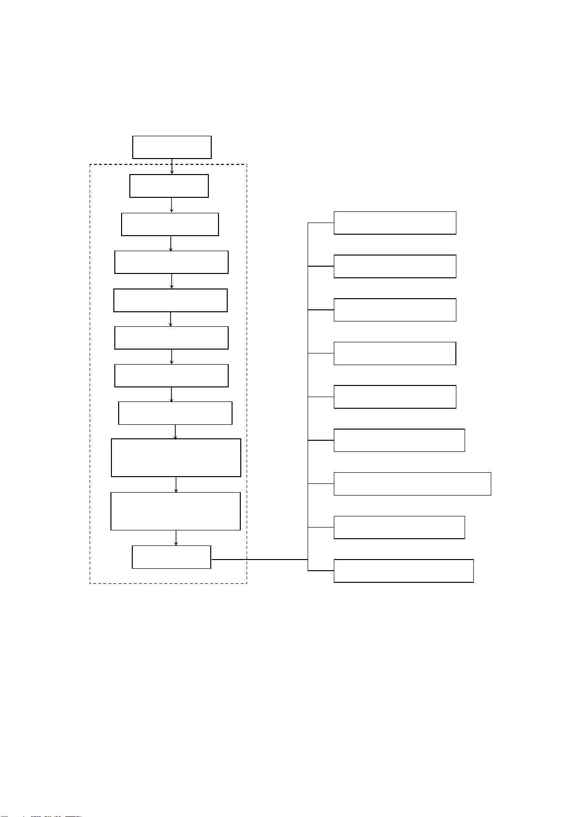
E2PROM copy
VIF adjustment
S-TRAP adjustment
H VCO adjustment
OSD adjustment
B+ adjustment
RF AGC adjustment
Focus adjustment
Screen-grid voltage white
balance adjustment
Scan amplitude, center and
raster adjustment
Check
Fig-1 alignment flow
High voltage check
X-ray protect check
Filament voltage check
Picture and sound check
Sub brightness check
White balance check
Color Purity, convergence check
AV terminal check
The unit and remote control
3
Page 6

3. Factory menu adjustment (FACTORY MENU PAGE)
3.1 VIF adjustment
Receive a NTSC signal at will, enter factory menu VCJ ADJ, select VIF VCO, press “VOL+/_”, then
display “END” and it means IC has adjust IF to 45.75MHz automatically.
3.2 S-TRAP adjustment
Receive a NTSC signal at will, enter factory menu VCJ ADJ, select S-TRAP, press “ VOL+/_”, then IC will
adjust S-TRAP to the best situation.
3.3 H VCO adjustment
Receive a NTSC signal at will, enter factory menu RASTER ADJ, select H VCO ADJ, press “ VOL+/_”,
then IC will auto adjust H VCO to the best situation.
3.4 OSD adjustment
Receive NTSC signal, check the OSD, if OSD is not at the center of the screen, you can adjust ”110:
OSD H-POS” of the last page of SERVICE MENU.
3.5 B+ voltage adjustment
a) Make sure that the power is AC 120V/60Hz
b) Connect B+ point with a digital voltmeter, receive A-7 signal, set the picture to “standard”, the
value of B+ voltage should be 110 V ±0.5 V(13”, 20”), 130V ±0.5 V(24”), 135V±0.5 V(27”).
3.6 RF AGC adjustment
RF AGC is auto adjusted by the turner.
3.7 Focus adjustment
a) Receive A-12 PHILIPS signal, set user control to “standard”.
b) Adjust focus electrode potentiometer on FBT to optimize focus of screen.
3.8 Screen-grid voltage and white balance adjustment
a) Receive A-7 signal, set user control to “user” and the brightness, contrast and color are zero.
b) Adjust potentiometer of SCREEN till the top side seven lattices slightly light up.
c) White balance adjustment of analog TV channel and AV channel.
Input erect 10-gray scale signal of VP403, at AV channel, set user control to “standard”. Adjust
the center of the right third level of dark balance and the center of the left second level of bright
balance. Enter CRT ADJ of factory menu, fixed CUT G(150), adjust CUT R, CUT B, DRV-R,
DRV-B till the white balance is normal basically.
d) White balance adjustment of COMPONENT channel and digital TV channel.
Input erect 10-gray scale signal of VP403, at COMPINENT channel, set user control to
“standard”. Adjust the center of the right third level of dark balance and the center of the left
second level of bright balance. Enter CRT ADJ of factory menu, fixed CUT G YUV(150), adjust
CUT R YUV, CUT B YUV, DRV-R YUV, DRV-B YUV till the white balance is normal basically.
Then enter CR PED, CB PED to adjust the dark balance of COMPONET channel again, in
order to let it more accurate.
Enter digital TV channel and check if the balance is up to the mustard, if not, adjust CUT R DTV,
CUT G DTV, CUT B DTV. The adjust method of DTV R PED, DTV B PED is as same as it of
COMPONENT channel
3.9 line, field center adjustment
Receive CENTER CROSS 100IRE signal of VP403, set user control to “standard” of AV channel, enter
RASTER ADJ item, adjust field center V-POS, line center H-POS, let the center of picture coincide with
center of screen.
3.10 line, field amplitude adjustment
4
Page 7

a) field amplitude adjustment
Receive PERCENT OVERSCAN signal of VP403, set user control to “standard” of AV channel, enter
RASTER ADJ item, adjust field amplitude V-SIZE, let the vertical reproduction ratio of picture acceptable
5%.
b) line amplitude adjustment
receive PERCENT OVERSCAM single of VP403, set user control to “standard” of AV channel.
13” and 20”: adjust B+ potentiometer RP502, let the line reproduction ratio of picture acceptable 5%.
20”, 24” and 27”: enter RASTER ADJ item, adjust line amplitude H-SIZE, let the line reproduction ratio of
picture acceptable 5%.
3.11 line, field linearity and geometry adjustment
receive CROSSHATCH single of VP403, set user control to “standard” of AV channel.if the linearity and
geometry are not satisfied, you may adjust the following items of RASTER ADJ:
Corner PARA
Trape VS-CORE V-LIN
Note: CORNER, PATR, TRAPE need not adjust at 13” and 20”.
4. Checking point
4.1 High voltage check
Connect High Voltage meter between CRT second anode and GND.
1) Receive A7 signal, set user control to “STANDARD”, measure the high voltage value, the reading
should be the value below:
13”: 22 kV±1 kV 20”: 25.5 kV±1 kV
24”: 27 kV±1 kV 27”: 29kV±1 kV
2) Set the brightness and contrast to minimum (zero beam current), measure the high voltage, the
reading should not exceed 33kV.
4.2 CRT filament voltage check
Receive A7 signal, set picture to “STANDARD”, use effective voltage meter to measure CRT filament
voltage, the reading should be (6.3±0.3) Vrms
4.3 X-ray protection check
1) Receive A7 signal, set user control to “vivid”.
2) 13”, 20”, 24”: Short circuit R309 (TP302, TP303), X-Ray protection circuit should function.
27”: press S301, X-Ray protection circuit should function.
4.4 Picture and sound check
1) Receive standard TV signal, include NTSC and ATSC.
2) Use picture control buttons to check color, contrast, brightness, sharpness, tint’s function.
3) Use sound control buttons to check volume control function.
4.5 Sub-brightness, sub-contrast check
1) sub-brightness check
Receive full-screen 8IRE signal of VP403, set user control to “standard” and check if it is satisfied (for
example: BESTBUY require brightness of 7.5IRE BLACK ≤0.20 ft.L), if not, enter PICTURE ADJ item.
AV channel: ATV BRIGHT
COMPONENT channel: YUV BRIGHT
DTV channel: DTV BRIGHT
Fine adjust the items to let it be satisfied (suggest 0.15 ft.L ≤BLACK brightness ≤0.20 ft.L).
2) sub-contrast check
Receive window 100IRE signal of VP403, set user control to “standard” and check if it is satisfied (for
5
Page 8
example: BESTBUY require brightness of window 100IRE≥70 ft.L), if not, enter PICTURE ADJ item.
AV channel: ATV CONTRAST
COMPONENT channel: YUV CONTRAST
DTV channel: DTV CONTRAST
Fine adjust the items to let it be satisfied.
4.6 Color purity and convergence check (in normal way)
4.7 AV/S terminals video and sound IN/OUT check
4.8 COMPONENT channel video and sound IN check.
4.8 Other buttons on the TV set and remote controller function check.
5 Ex-factory setting
Enter factory menu SHIPMENT OFF, press right button to let OFF turn to ON, then exit the factory menu.
5.1 picture menu
CONTRAST 45
BRIGHTNESS 35
COLOR 45
TITN 0
SHARPNESS 30
PICTURE MODE STANDARD
▽MORE
5.2 Volulme: 30
5.3 Language: English
5.4 TV mode: channel 2
6 Factory menu
6.1 enter factory menu method
1) Press factory button to enter factory menu.
2) Press CH+ or CH- to select sub-menu and VOL+ or VOL- to enter.
3) Press MENU to exit.
6.2 the content of factory menu see table 1
table 1 factory menu
FACTORY MENU
01. VIF VCO VIF VCO auto regulation
1: VCJ ADJ
2: RASTER ADJ
02. RF DELAY TUNER AGC adjustment
03. S-TRAP S-TRAP auto regulation
06. H VCO H VCO auto regulation
07. V-POS Field center adjustment
08. V-SIZE Field amplitude adjustment
09. V-LIN Field linearity adjustment
10. VS-CORE Corner adjustment
6
Page 9

11. H-POS Line position adjustment
12. H-SIZE Field amplitude adjustment
13. PARA Pincushion adjustment
14. CONTER Angle adjustment
15. Trape Trapezia adjustment
16. CUT R TV-NTSC, AV white balance adjustment
17. CUT G
18. CUT B
19. DRV-R
20. DRV-B
21. CUT R YUV COMPONENT white balance adjustment
22. CUT G YUV
23. CUT B YUV
24. DRV-R YUV
3: CRT ADJ
4: PICTURE ADJ
5: SHIPMENT OFF User menu pre-set
6: SERVICE MENU E2 reference
7: AGING OFF
25. DRV-B YUV
26. CR PED
27. CB PED
28. CUT R DTV TV-ATSC white balance adjustment
29. CUT G DTV
30. CUT B DTV
31. DTV R PED
32. DTV B PED
33. Y R OFSET Correction offset, 30
34. YUV B ADD Correction offset, 30
35. YUV B DEC Correction offset, 30
36. ATV BRIGHT TV-NTSC, AV Sub bright adjustment
37. ATV CONTRAST TV-NTSC, AV Sub contrast adjustment
38. YUV BRIGHT COMPONENT Sub bright adjustment
39. YUV CONTRAST COMPINENT Sub contrast adjustment
40. DTV BRIGHT TV-ATSC Sub bright adjustment
41. DTV CONTRAST TV-ATSC Sub contrast adjustment
Aging switch, after aging function turns on, the unit
will auto turn on and display HR sign on the top left of
the screen, press return button to enter the factory
menu
7
Page 10

Working principle:
The unit adopts the super single IC R2J10165(N102) with I2C bus controlled processor produced by
RENEsAS, which includes IF, color decoder, 8-bits MCU, pre-video amplify, H/V deflection, AV switch,
audio processing, ect.. The main interfaces are: one AV IN, one S-VIDEO IN, YCbCr, one AV OUTPUT.
The signal flow is below:
The antenna reception signal RF will be sent to the integrative tuner (contains HF and IF amplifier
circuits), which is controlled by SDA and SCL, selects appropriate channel and sends the selected IF
signal to the next level for processing.
If receive the analog RF signal, RF will be sent to tuner, via HF and mixing, output IF, via V111 after, it
sent to SAW Z101 filtering and gain better IF. Then it feed to main IC N102 (R2J10165) from 38#, 39# IF
amplify, phase-lock loop VCO and synchronous detection, output from 34# as composite video signal
VIF-VIDEO. After filtering, VIF-VIDEO changes to VIDEO-TV.
If receive the digital RF signal, the signal via HF and IF amplifying, output differential digital IF signal
form 10#, 11#, then feed to NH07(R8A66953) demodulate and MPEG decoder, output YCbCr of
DTV( DTV-Y and DTV-CbCr) and audio DTV-L/R.
VIDEO-TV, DTV-Y, Y component from YCbCr and V/Y signal of AV1/S, AV2 selected by switch NB04
(TC4053), they are all sent to NB01(TC4052)9#,10# select, output VIDEO, it will be sent to N102 form
32#. C of S terminal is sent to N102 30#. Components Cb, Cr and DTV-CbCr demodulated and MPEG
decoded by R8A66953 are sent to N102 19#,20#, then switch selection, video decoding and processing,
it sent to the internal RGB interface matrix, pre-video amplify, contrast, bright and blacking, output RGB
form 51#,52#,53#. After N102 internal video switch selecting, the video is sent to decoding and
processing, it also output from 24# as AV OUT.
The main IC N102 has the H/V deflection internal. VDRV output from 11#, via N301(TDA8172)
amplifying to push the vertical deflection coil. HDRV output from 15#, via V301(ST1803DF) driving to
push the horizontal deflection coil. EW-OUT output form 25# via V303(2SC3852) driving then sent to the
horizontal deflection.
The IF signal is sent to N102 from 38# 39# demodulating TV audio L/R. L/R of AV1/S, AV2 via audio
switch NB04(TC4053) selecting, L/R of YCbCr and DTV-L/R demodulated and MPEG decoded by
R8A66953, it sent to N102 29#,43# switch selection and audio process together with TV audio signal,
then output L/R from 46# 48#, it sent to sound amplifier NV01(AN7522) amplifying to push the speaker;
at the same time, the L/R from 46# 48# is also audio of AV OUT.
The unit is control by the MCU built in N102, it connects tuner and E2PROM through IIC bus line and
controls the whole unit working.
8
Page 11

Block diagram
9
Page 12

IC Block diagram:
1.R2J1016XFP
10
Page 13

2.STR-W6553A
Pin function:
No STR-W6500
[T0220F-6L]
1 D Drain terminal Drain of MOSFET
2 - S
3 S/GND GND
4 Vcc Power terminal Control power input
5 SS/ADJ Soft-Start/over current
6 FB Feed Back terminal Timing voltage control signal input
7 BD Bottom check terminal Bottom check signal input and
STR-X6500
[T03PF-7L]
Name Function
Source/Ground terminal MOSFET Source and Ground
Over current protect and Soft-Start
protect
timer adjust
Gap oscillation control
external Latch signal input
11
Page 14

3. AN7522N
The AN7522 is a monolithic integrated circuits designed for 3.0WX2 channel BTS(8V, 8Ω)output audio
power amplifier.
Vcc
GND
4.TDA8177
Designed for monitors and high performance TVs, the TDA8177 vertical deflection booster delivers
flyback voltages up to 70V.
The TDA8177 operates with supplies up to 35V and provides up to 3App output current to drive the yoke.
The TDA8177 is offered in HEPTAWATT package
12
Page 15

5.R8A6695SFP
13
Page 16

14
Page 17

15
Page 18

Troubleshooting guide
1. no raster, no sound
The light is red, press
POWER can’t turn on
the TV
Check if N102 56#
output high level
Check if it is X-RAY
protection
2. with picture, without sound
Check if sound
amplifier NV01 has
output
If NV01 pin 6 and
pin8 have input
signal
Check if NV01 power supply is
normal, if pin9 (mute) is high level
Press POWER to
turn on and the
light is blue
Check if N102 and
N101are normal
Refer to 2 and 3
No
Yes
If the power
Yes No
Yes
No
indicator is
light?
Speaker is
damaged
Check if N102
46# and 48# have
output signal
Check if
FU501 is
melted?
No
Check if
C510 has
300V?
Ye s
Check N501
N502 and
their
periphery
Yes
No
There is short circuit
at primary or
secondary coil of
power
Check D501
and its
periphery
16
Page 19

3. with sound, without picture
With sound but without
picture
No raster
Check if B+
is normal
Have raster
Check if
No
N102 has
RGB output
Check N102
and its
periphery
If H/V circuit
works
normally?
Normal
Check if each
group voltage of
FBT is normal
Abnormal
If V301C#
output
H-frequency
If V301 is
damaged
Check CRT
board, turner and
its periphery
Ye s
Check CRT
board and
filament voltage
17
Page 20

Page 21

Page 22

Page 23

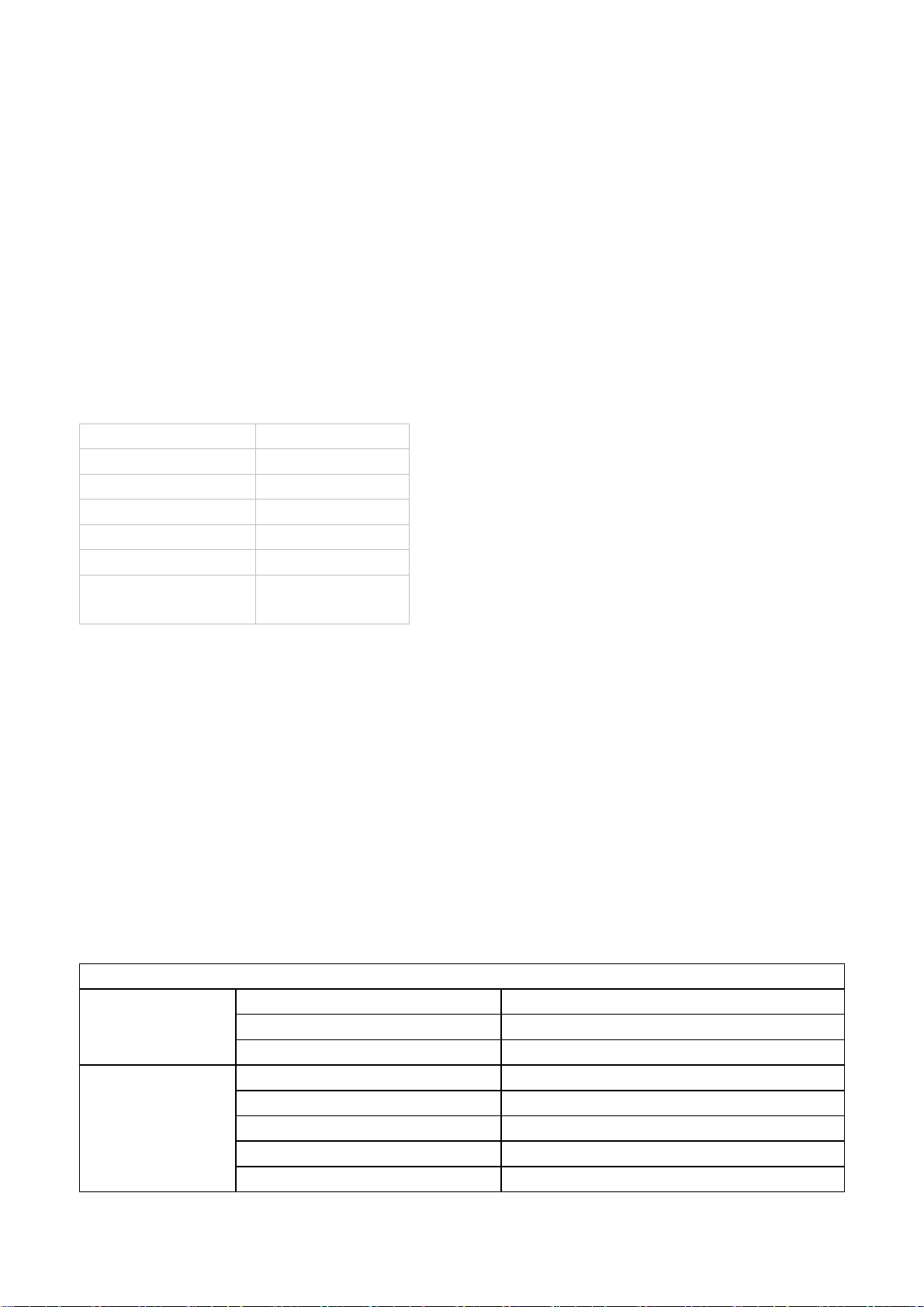
APPENDIX-A: Main assembly list
NAME NO. MAIN COMPONENT AND it’S NO.
Main board 667.TQD26-01H N102
N301
NV01
N501
TUNER101
T301
DTV digital processing
board
Side AV board 667.TQ2426H-29
Keypad board 667.TQ2426H-05
CRT board 667.TQ2092H-02
STANDBY board 667.TQ24261-05
Remote control 301.VTQ2092-21B RC-V21-0B
CRT 335.2512B-60
667.TQ2092H-69 NH07 R8A66953 (353.66953-10)
R2J10165 (353.10165-10)
STV8172 (352.81720-20)
AN7522N (352.75220-00)
STRW6556 (352.65560-10)
ENV56M23D8F (590.40C09-00)
FBT/BSC26-N1013A (472.24216-00U)
Page 24

603-TQ24260-10
Ver.1.0
 Loading...