

Page 1
SERVICE SERVICE
MANUALMANUAL
Page 2

Contents
Safety Instruction………………………………………………………………………………1
X-ray radiation protection……………………………………………………………………..1
Safety Measures…………
Points of attention for product safety………………………………………………………………3
…………………………………………………………………………..2
Alignment procedures………………………………………………………………………4
Adjustment equipment……………………………………………………………………..5
Adjustment instruction…………………………………………………………………………5
Factory adjustment method………………………………………………………………………..5
IF amplification adjustment…………………………………………………………………….5
B+ confirmation
AGC adjustment…
Sound detection…………………………………………………………………………………….6
Adjustment of Focus Potentiometer……………………………………………………………….6
Alignment of line certer…
Field amplitude, field S alignment, field center, line amplitude, E/W alignment etc. ……………6
Adjustment of screen-grid VG2……………………………………………………………………….7
White balance adjustment…………
Inspection of the high voltage and filament voltage………………………………………………….7
Inspection of X-ray protection………………………………………………………………….7
…………………………………………………………………………………….5
………………………………………………………………………………..5
………………………………………………………………………..6
…………………………………………………………..7
Inspection of beam current…………………………………………………………………..7
Inspection of AV function……………………………………………………………………………….7
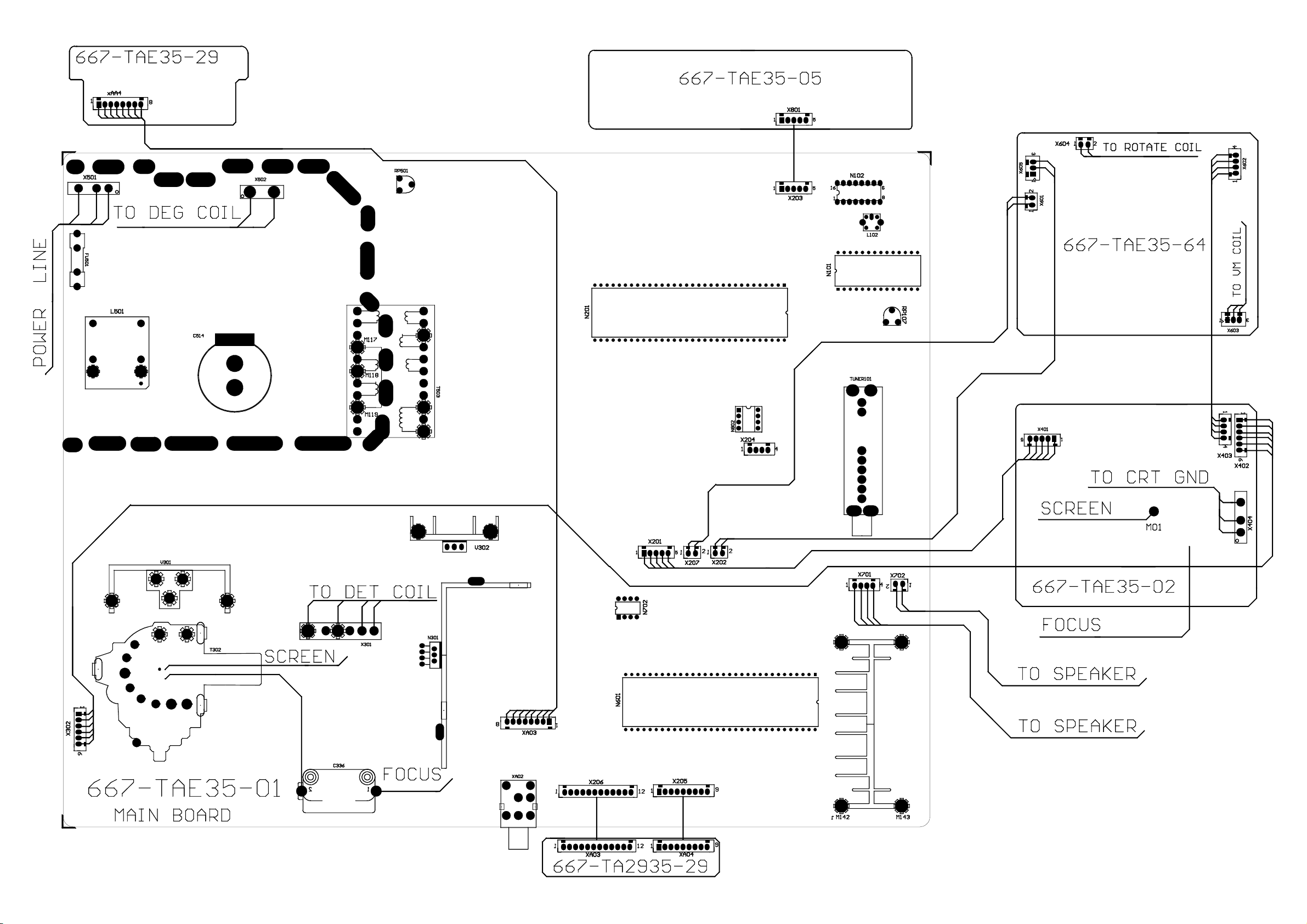
Wiring diagram…………………………………………………………………………….8
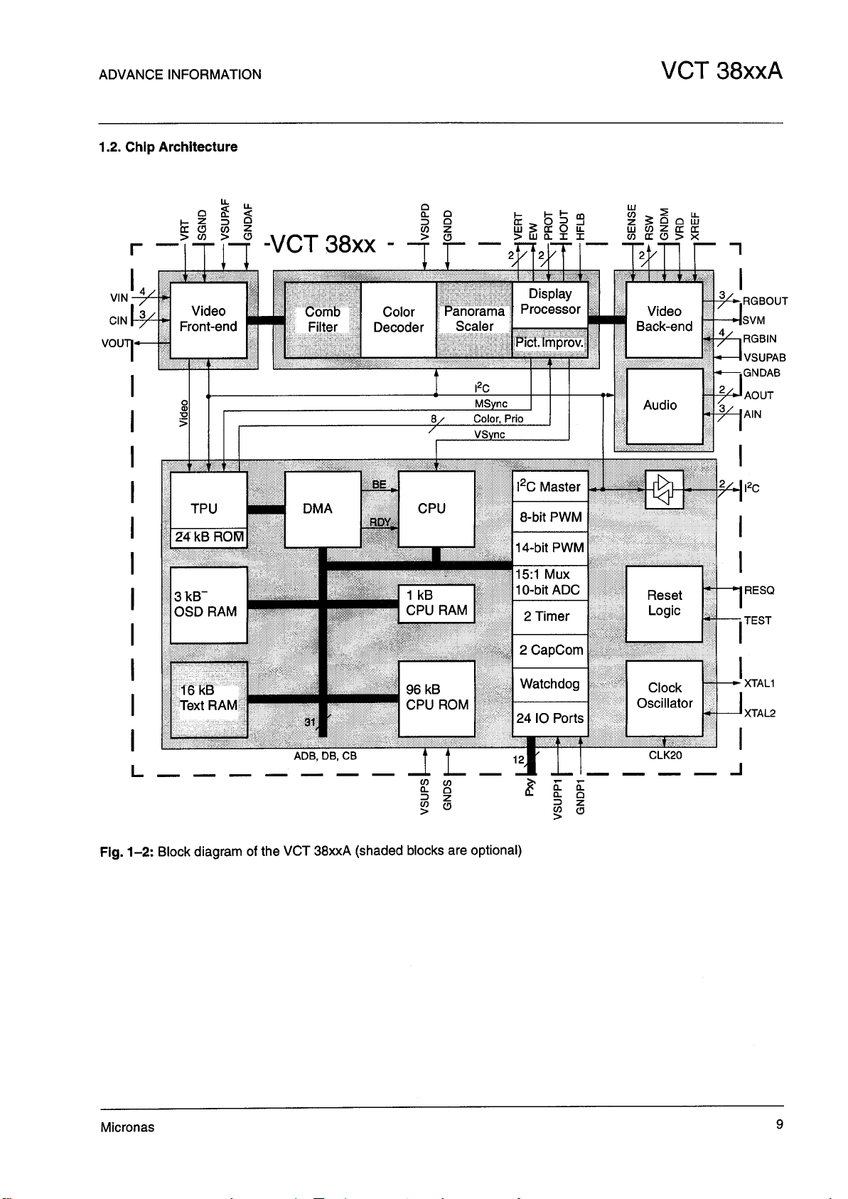
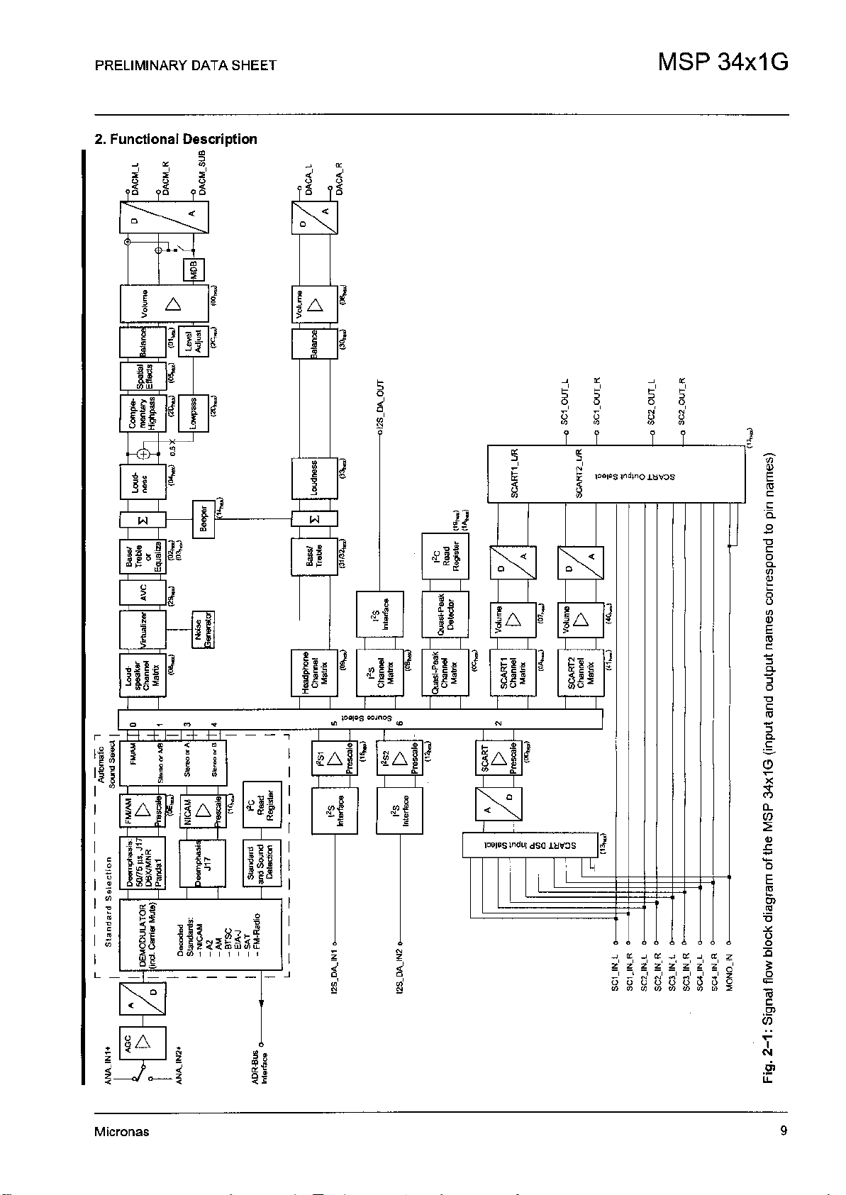
IC block diagram…………………………………………………………………………..9
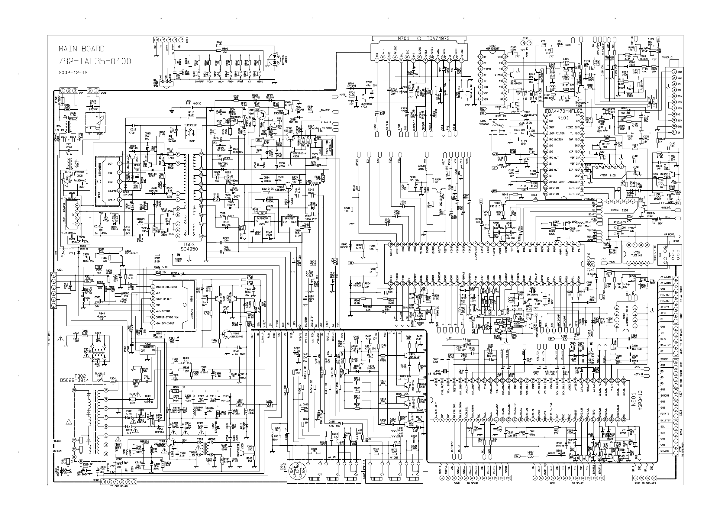
Schematic diagram…………………………………………………………………………….11
Electrical parts list ……………………………………………………………………………..13
Assembly drawing of complete set …………………………………………………………34
Detail list of Assembly drawings……………………………………………………………
35
0
Page 3

Attention: This maintenance manual is only intended for the professional maintenance
personnel to take reference with. Before repairing TV set please carefully read
the following points of attention.
Safety Instruction
Before fixing and aligning this set, please read the following “Points of attention for
Safety “, “Points of attention for Safety of Components” and “X-ray Radiation
Protection“.
Points of attention for Safety
1. Because the city power is connected directly to the hot earth of power supply PCB, in order to
avoid electric shock or damage to instruments, an isolate transformer must be applied during the
fixing procedure.
2. Before moving the CRT, graphite layer conductor must be discharged.
3. Before replacing any components, the power plug must be taken out from the power supply
socket.
4. Before replacing large power resistor, 10mm high must be kept between resistor and PCB.
Points of attention for the components safety
There are many electric and mechanical components on the PCB that are related with the
safety features. These features are not easily visible. Replacement parts that have special safety
characteristic are indicated in the Instruction Manual. Electric components with such features will be
labeled with shadow or labeled with in the detail list. When changing these components, please
refer to the detail list in the manual. Components that have different specification from that in the
detail list may not have the same safety features. They may cause electric shock, fire, increase of
X-ray radiation or other damage.
1. Safety instruction
Before fixing or aligning this set, please read the following “ X-ray radiation protection”, “Safety
measures” and “Points of attention for products”.
1.1 X-ray radiation protection
1.1.1 Too high voltage will produce radiation harmful to human health. To avoid such risk, the
high voltage should be regulated within the limited value. For 25”, the normal value of beam
current should be 26.5 kV at 1.3 mA, for 29”, 29kV at1.4 mA and for 29” pure flat TV set,
30kV.
Under any circumstances, the high voltage should not exceed 31kV (25”), 33 kV (29”), 35kV
1
Page 4

(29” pure flat). When the TV set needs to be fixed, please follow the inspection procedures of
high voltage in item 4.11 under this instruction ”Inspection of high voltage”. It is suggested that
the value of high voltage be recorded as part of maintenance work. It is most essential at the
same time to use precise and dependable high voltage meter.
1.1.2 This set is equipped with X-ray over radiation (FS) protection circuit to prevent over radiation
of X-ray in the case of abnormal increase of B+ voltage in the set. Whenever fixing the set,
FS circuit must be checked according to the inspection procedures as in item 4.11.5 of this
instruction, ”X-ray radiation protection test” to make sure the circuit functions well.
1.1.3 The only source of TV set producing X-ray is CRT. To avoid X-ray radiation during the whole
process, the exact same type of CRT designated in the detail list must be replaced, when
there is a need to change CRT.
1.1.4 When deciding on the same type of 4, as some components of this TV set are related to the
safety characteristic, please read the “Points of attention for products safety” before changing
the components, for the sake of safety.
1.2 Safety measures
1.2.1 When the TV set is working, the high voltage will be as high as approximately 31kV. When
adjusting the set after removing the cover or opening the back cabinet there will be risk of
electric shock, so
a) Before detaching the anode cap, please discharge it several times by grounding the anode
of CRT to earth many times to avoid electric shock.
b) Before moving the CRT, its anode must be thoroughly discharged. The CRT is a high
vacuum part. Once broken, its fragments will fly out violently. Therefore it must be very
careful in dismantling and loading it.
1.2.2 There are a lot of electronic and mechanical components in PCB that have safety related
features. They are indicated with shadow in the circuit diagram. Please carefully read the
detail list before changing these components.
1.2.3 If the fuse is blown, please change it for the one designated in the list of components.
1.2.4 When changing resistors of 1w or bigger than 1w in PCB, make sure to separate them from
the PCB by10 mm.
1.2.5 Make sure that the wire stays far away from the high voltage or high temperature
components.
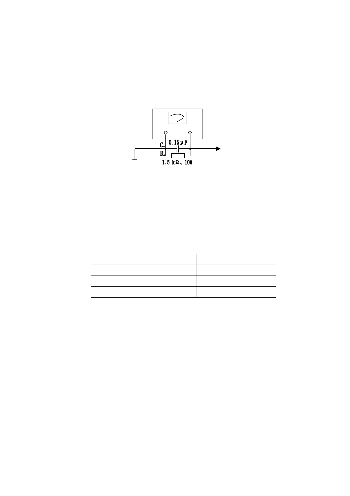
Check for the AC leakage current of the metal components exposed out of the cover such as
1.2.6
antenna terminal, screw, metal surface and control axis. Make sure that the cabinet of TV set
is absolutely safe in operation, free from any risk in electric shock. Insert the power supply
plug directly into the 220v AV socket (No isolate transformer will be applied during the test).
Use an AC voltage meter with sensitivity of 5 kΩ or higher per volt to measure the leakage
current according to the following steps:
First, connect in parallel a resistor of1.5 kΩ,10 W resistor and a 0.15 μF capacitor (AC type)
2
Page 5
A
r
between the known good earthing connector (such as underground metal tube) and the
exposed metal parts out of the cabinet. Measure AC voltage across both terminals. Then
exchange the two pins of AC before re-measuring every exposed metal parts. The measured
value of voltage should not exceed 0.3V effective value, which corresponds to current.0.2mA
If the value exceeds this specified value, aligning must be made at once.
C Volt Mete
Good Earth Connect Point
(Such as underground metal etc)
Figure 1
1.2. 7 DC voltage breakdown test
The following touchable parts must be subject to 1s anti voltage test before packing. The
voltage is applied between the plug pin of the power supply and the exposed metal parts for
the test and the volt value should be AC 3000V.
Parts designation: Position:
Antenna terminal Back cover
This detector is placed
respectively at every
exposed metal parts.
External cover screw Back cover
AV interface Back cover, sides
1.3 Points of attention for product safety
There are many electric and mechanical parts in this PCB that are related to safety. However,
they are often neglected from visual look. For changing the high voltage and high power parts,
very often it’s impossible to provide them with effective “X-ray radiation” protection. All these
exchange parts with safety characteristic are designated in the detail list. All the electronic
parts with such characteristics are indicated with shadow in the circuit diagram.
When changing these parts, please carefully check the detail list.
3
Page 6
t
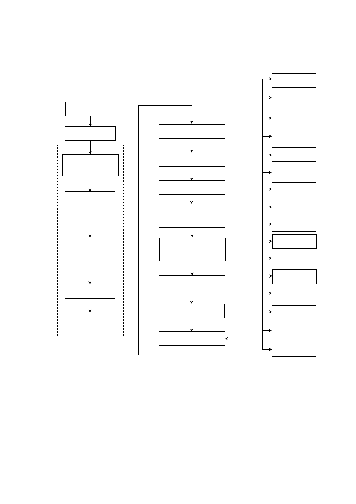
2 Flow chart of Adjustment and aligning
IF Test
Com
EEPROM
casse
B+volt and 5V-3V
check
Field amplitude,
field linearity
Line amplitude
and east-wes
RF AGC setup
Sound check
Focus course
VG2 adjustment
White balance and
Line field, center and
field amplitude, reset
Set R378 to optimize
Field center
Line amplitude and
Focus fine adjustment
check
High volt
Filament volt
X-ray
Picture &
White
Dark balance
Color
SCART JACK
Brightness
Earphone
jack
Set Av terminal
Sound power
Check of key
Check on
Assembly
Safety check
See Fig.2
4
Page 7

3. Alignment Equipment
3.1 DC Current Stabilizer Power Supply PAB18-1.8
3.2 Audio Frequency Voltage Meter
3.3 Oscillograph
3.4 High Voltage Meter
3.5 Digital Multi-meter
3.6 AC breakdown test meter
3.7 IFT Signal Gene
4. Alignment Instruction
4.1 Factory Alignment Methods
4.1.1 Push composed keys → --/--- → to enter factory menu.
4.1.2 There are totally three pages of factory menu. Turn the page by pushing “MENU”, Move the
items by CH+/CH- key, Adjust the value by VOL+/VOL-. After adjustment, push “OK” for save.
4.1.3 The method to quit factory menu: Under the item VCT in SERVICE XOCECO-50 Hz, push
EXIT: OK
4.2 IF amplifier alignment
a) Connect the positive pole of TP5. C219 to DC 5v, TP2 or TP7 to positive pole DC 8v, TP6 to
earth, TP4 to multi-meter.
b) Connect 38.9M, PAL DK IF signal to TP1 through 1000p capacitor, adjust IFT L102 with zero
inductance screwdriver, to make the readout of multi-meter as 2.5V±0.1 V.
c) Connect 33.9M SECAM L IF signal to TP1 through 1000P capacitor, apply voltage 5v at TP1,
TP3, TP8, adjust RP101 with zero inductance screwdriver, to make the readout of
multi-meter as 2.5V±0.1 V.
d) After adjustment, connect the IF line disconnect point of tuner, seal L102 with wax, point glue
RP 101.
4.3 B+ confirmation
Determine the B+ voltage by DC meter, DC 200V ( C503 two poles) , the value should be 135
V±0.5.
4.4 AGC adjustment
4.4.1 Receive D-8 signal 60db, determine the voltage of positive testing pole of C114 with DC
voltage meter.
4.4.2 Adjust potentiometer RP107, to make the voltage readout of voltage meter to be 4.1 V±
0.1V.
4.4.3 Input 100db from antenna, and the picture should not appear as asynchronized and
distorted. Input 35db-40db weak signal, and the color should not disappear, the picture
should be synchronized, and the sound is normal.
5
Page 8

4.5 Sound inspection
4.5.1 Receive 1kHz sound signal 100% modulated and connect X701 with 8Ω false resistances
(load). Connect sound voltage meter and Oscillograph to two poles of the false resistances.
4.5.2 Turn the sound to the biggest volume. Balance the sound and set the high/low sound to the
middle, MSS OFF, DBE OFF, and the sound power should be ≥7 W×2(about 7.5 Vrms),
distortion≤7% (A slight peak cutting at maximum sound sine wave is allowed.)
4.6 Alignment of focus potentiometer
4.6.1 Pre-warm the TV set for 30 minutes.
4.6.2 Receive the signal from testing card.
4.6.3 Push the key of picture mode to place analog in “dynamic”.
4.6.4 Adjust potentiometer of FOCUS on the FBT to make the picture to be best focused.
4.7 Alignment of line center
4.7.1 Receive 50 HZ signal from video head.
4.7.2 Enter the factory menu RGB HOR. POSITION item under AV status, adjust amplitude of RGB,
and make the picture to be symmetry. Then save.
4.7.3 Receive 60Hz video signal and enter the factory menu RGB HOR.POSITION item under AV
status. The adjusting method of POSITION is same as 4.7.1~4.7.2.
4.7.4 Adjust separately under following four modes
a)50 Hz 4: 3;
b)60 Hz 4: 3;
Of which Vert position is unnecessary for readjustment after setup at the initial value. Adjust
the value of R378 to optimize it (set it up during the production in the factory).
4.8 Field amplitude, field S alignment, field center, line amplitude, E/W alignment etc.
Enter the corresponding item of factory menu and adjust the geometric distortion until accepted.
Hor Amplitude
Cushion
Trapeze
Angle
Bow
Hor Symmetry
Hor Corners
Vert position
Vert Amplitude
Vert S-Correction
Vert S-Symmetry
6
Page 9

The adjustment result should satisfy the scan linear geometric distortion and over scan (rate of
recurrence)
4.9 Adjustment of screen-grid Focus and VG2
4.9.1 Adjust FBT Focus pole potentiometer until picture is clear.
4.9.2 Enter factory menu Cathode current (G2) item, (AV should be kept empty then), push VOL+,
change to bright horizontal line and adjust the potentiometer of the line pack acceleration pole
in such a way that the bight horizontal line becomes slightly bright.
4.10 White Balance Adjustment
4.10.1 Enter “Cutoff ref” adjustment of factory menu. It’s enough only to fine adjust the dark
balance. Under 4.5 Niete, color temperature 12000K+8MPCD(X=0.270,Y=0.283).
4.10.2 Enter Drive ref item adjustment of factory menu. The bright balance will be automatically
adjusted at a certain white coordinate place. Under 60 Niete, color temperature
2000K+8MPCD(X=0.270,Y=0.283).
4.11 Inspection of the high voltage and filament voltage
4. 11. 1 Connect high voltmeter between the high voltage cap and the earth. Measure the filament
voltage with an actual value and effective voltage meter.
4.11.2 Receive D35 signal, set the picture mode at “dynamic”, and measure the high voltage and
filament voltage. The voltage for 29” “Yongxin” extra pure flat should be: high voltage- 29 kV
±0.5 kV; 29″pure flat, high voltage- 30 kV±0.5 kV,filament voltage- 6.3±0.3 Vrms.
4.12 Inspection of X-ray protection
4.12.1 Receive normal picture.
4.12.2 Push switch S301. The line scan should stop vibrating and shut the set off.
4.12.3 Shut off the main power supply, re-power it on in 30 seconds. It should be back to normal.
4.13 Inspection of beam current
Receive D35 signal, set the picture mode at “dynamic”, and measure the two terminals of TP9,
TP10. For ultra pure flat it should be ≤1.6 V, and for 29″pure flat, ≤1.7 V.
4.14 Inspect ion of AV function
VIDEO IN: 1 Vp-p 75Ω, AUDIO IN: -8 dBm±3 dBm >47 kΩ.
As per instruction manual, connect audio and video equipment with AV terminal of the set to
be tested. The inter-connection should be made to meet the following requirements:
VIDEO IN: 1 Vp-p 75Ω, AUDIO I: -8 dBm±3 dBm >47 kΩ.
7
Page 10
Page 11
Page 12
Page 13
Page 14

Page 15

Page 16

Page 17

Y
T
WARNING: BEFORE SERVICING THIS CHASSIS, READ THE “X-RA
CAUTION: 1. The shaded areas makes in the schematic diagram and the parts list designate components
RADIATION PERCAUTION”, “SAFETY PRECAUTION” AND “RPODUC
SAFETY NOTICE” ON PAGE 1&2 OF THIS MANUAL.
which have special characteristics important for safety and should be replaced only with
type identical to those in the original circuit or specified in the parts list. Before replacing
any of these components, read carefully the PRODUCT SAFETY NOTICE on page 2.
2. Do not degrade the safety of the receiver through improper servicing.
ELECTRICAL PARTS LIST
MAIN BOARD
SYMBOL PART NO. DESCRIPTION
782-TAE35-010A MAIN PCB
CRYSTAL
G601 329-61801-00 HC49US 18.432MHZ
G201 329-62001-00 CAST5 20.25MHZ
RECTIFIER
D506 340-80010-00 RUIP
D501 340-80019-00 T3SB60
DIODE
D705 340-00001-00 1N4148
D527 340-00288-003 TFR155
D304 340-00014-00 RGP10J
D315 340-00060-00 RGP25K
D101 340-00170-00 MA859
D513 340-00256-00 BYT56M
D514 340-00283-00 TRU3YX
D515 340-00283-00 TRU3YX
D516 340-00284-00 TRU4YX
D526 340-00291-00 TEU2YX
D502 340-00292-00 TRU3A
D312 340-00297-00 ERD07-15
D511 340-00309-00 RG4
D204 340-00001-003 1N4148
D601 340-00001-003 1N4148
D701 340-00001-003 1N4148
D602 340-00001-003 1N4148
D702 340-00001-003 1N4148
D525 340-00001-003 1N4148
D508 340-00001-003 1N4148
13
Page 18

SYMBOL PART NO. DESCRIPTION
D512 340-00001-003 1N4148
D503 340-00001-003 1N4148
D504 340-00001-003 1N4148
D509 340-00001-003 1N4148
D510 340-00001-003 1N4148
D507 340-00001-003 1N4148
D704 340-00001-003 1N4148
D524 340-00001-003 1N4148
D402 340-00001-003 1N4148
D403 340-00001-003 1N4148
D528 340-00001-003 1N4148
D361 340-00001-003 1N4148
D100 340-00001-003 1N4148
D307 340-00010-003 S5295G
D302 340-00010-003 S5295G
D313 340-00014-003 RGP10J
D303 340-00014-003 RGP10J
D301 340-00014-003 RGP10J
D363 340-00014-003 RGP10J
D305 340-00086-003 TVR-1B
REGULATED DIODE
D310 340-51850-00 HZ18-3
D202 340-50560-00 HZ6B1
D203 340-50560-00 HZ6B1
D360 340-50470-003 HZ5B1
D308 340-50470-003 HZ5B1
D309 340-50470-003 HZ5B1
D205 340-50510-003 HZ5C2
D206 340-50510-003 HZ5C2
D518 340-50560-003 HZ6B1
D517 340-50610-003 HZ6C2
D523 340-50650-003 HZ7A2
D603 340-50810-003 HZ9A2
D314 340-50910-003 HZ9C1
D201 340-50910-003 HZ9C1
D521 340-50910-003 HZ9C1
D505 340-51560-003 HZ16-1
TRANSISTOR
V106 343-10150-10 2SA1015Y
V503 343-01800-00 KSE180 TO-126
V506 343-01800-00 KSE180 TO-126
V109 343-12040-00 RN1204
V507 343-16680-00 2SA1668
V504 343-24820-00 2SC2482
V301 343-25390-00 2SD2539
14
Page 19

SYMBOL PART NO. DESCRIPTION
V302 343-38520-00 2SC3852
V101 343-23690-004 PH2369
D519 343-00420-404 SFORIB42
V501 343-04000-304 2SD400 E/F
V304 343-10150-104 2SA1015Y Pr2.5
V303 343-10150-104 2SA1015Y Pr2.5
V201 343-10150-104 2SA1015Y Pr2.5
V502 343-10150-104 2SA1015Y Pr2.5
V702 343-10150-104 2SA1015Y Pr2.5
VA01 343-10150-104 2SA1015Y Pr2.5
V405 343-10150-104 2SA1015Y Pr2.5
V406 343-10150-104 2SA1015Y Pr2.5
V407 343-10150-104 2SA1015Y Pr2.5
V204 343-18150-114 2SC1815-Y
V205 343-18150-114 2SC1815-Y
V206 343-18150-114 2SC1815-Y
V508 343-18150-114 2SC1815-Y
V102 343-18150-114 2SC1815-Y
V103 343-18150-114 2SC1815-Y
V107 343-18150-114 2SC1815-Y
V408 343-18150-114 2SC1815-Y
V409 343-18150-114 2SC1815-Y
V108 343-18150-114 2SC1815-Y
V505 343-18150-114 2SC1815-Y
V363 343-18150-114 2SC1815-Y
V104 343-18150-114 2SC1815-Y
V207 343-18150-114 2SC1815-Y
V110 343-18150-114 2SC1815-Y
V305 343-23830-604 2SC2383-0
V105 343-27170-004 2SC2717
CERAMIC CAPACITOR
C526 459-6210K-00 DE0705B102K1K
C204 459-2410R-00 DD308-63F104Z50
C616 459-2051H-10 CC1-08-CH-63V-51pF-J
C617 459-2051H-10 CC1-08-CH-63V-51pF-J
C220 459-2410R-00 DD308-63F104Z50
C203 459-2410R-00 DD308-63F104Z50
C100 459-2112H-102 CC45-CH1H121JYR
C215 459-2002C-102 CC45-CH1H020CYR
C214 459-2002C-102 CC45-CH1H020CYR
C647 459-2020H-102 CC45-CH1H200JYR
C646 459-2020H-102 CC45-CH1H200JYR
C644 459-2056H-102 CC1-08-CH-63V-56pF-J
C643 459-2056H-102 CC1-08-CH-63V-56pF-J
C202 459-2110H-102 CC45-CH1H101JYR
15
Page 20

SYMBOL PART NO. DESCRIPTION
C415 459-2110H-102 CC45-CH1H101JYR
C271 459-2122H-102 CC45-CH1H221JYR
C344 459-2122H-102 CC45-CH1H221JYR
C411 459-2122H-102 CC45-CH1H221JYR
C412 459-2122H-102 CC45-CH1H221JYR
C413 459-2122H-102 CC45-CH1H221JYR
C201 459-2122H-102 CC45-CH1H221JYR
C313 459-2133K-902 RBU07SL331K-H46CA
C316 459-2133K-902 RBU07SL331K-H46CA
C642 459-2147H-902 CC1-12-SL-63V-471J
C640 459-2147H-902 CC1-12-SL-63V-471J
C641 459-2147H-902 CC1-12-SL-63V-471J
C516 459-2168K-002 CK45-B1H681KYR
C525 459-2210K-002 CK45-B1H102KYR
C110 459-2210K-002 CK45-B1H102KYR
C151 459-2210K-002 CK45-B1H102KYR
C738 459-2210K-002 CK45-B1H102KYR
C739 459-2210K-002 CK45-B1H102KYR
C637 459-2215K-002 CT1-06-2B4-63V-152K
C639 459-2215K-002 CT1-06-2B4-63V-152K
C638 459-2215K-002 CT1-06-2B4-63V-152K
C606 459-2233K-002 CT1-08-2B4-63V-332K
C607 459-2233K-002 CT1-08-2B4-63V-332K
C311 459-2247R-002 CT1-08-2E4-63V-472Z
CA12 459-2247R-002 CT1-08-2E4-63V-472Z
CA15 459-2247R-002 CT1-08-2E4-63V-472Z
C538 459-2310R-002 CK45-F1H103ZYR
C539 459-2310R-002 CK45-F1H103ZYR
C561 459-2310R-002 CK45-F1H103ZYR
C563 459-2310R-002 CK45-F1H103ZYR
C140 459-2310R-002 CK45-F1H103ZYR
C141 459-2310R-002 CK45-F1H103ZYR
C142 459-2310R-002 CK45-F1H103ZYR
C143 459-2310R-002 CK45-F1H103ZYR
C608 459-2310R-002 CK45-F1H103ZYR
C609 459-2310R-002 CK45-F1H103ZYR
C713 459-2310R-002 CK45-F1H103ZYR
C118 459-2310R-002 CK45-F1H103ZYR
C116 459-2310R-002 CK45-F1H103ZYR
C117 459-2310R-002 CK45-F1H103ZYR
C128 459-2410R-002 DD308-63F104Z50
C569 459-2410R-002 DD308-63F104Z50
C122 459-2410R-002 DD308-63F104Z50
C267 459-2410R-002 DD308-63F104Z50
C269 459-2410R-002 DD308-63F104Z50
16
Page 21

SYMBOL PART NO. DESCRIPTION
C731 459-2410R-002 DD308-63F104Z50
C266 459-2410R-002 DD308-63F104Z50
C264 459-2410R-002 DD308-63F104Z50
C268 459-2410R-002 DD308-63F104Z50
C409 459-2410R-002 DD308-63F104Z50
C410 459-2410R-002 DD308-63F104Z50
C121 459-2410R-002 DD308-63F104Z50
C120 459-2410R-002 DD308-63F104Z50
C123 459-2410R-002 DD308-63F104Z50
C308 459-5133K-002 RQC05B331K-H46CA
C566 459-5133K-002 RQC05B331K-H46CA
C334 459-5139K-002 CK45-B2H391KYR
C529 459-5147K-002 RQC05B471K-H46CA
C528 459-5147K-002 RQC05B471K-H46CA
C527 459-5147K-002 RQC05B471K-H46CA
C335 459-5182K-002 DD06-999B812K500
C547 459-5210K-002 CK45-B2H102KYR
C501 459-B147M-20 ECK-DNS471MBX
C504 459-B147M-20 ECK-DNS471MBX
C520 459-B222M-20 ECK-DNS222MEX
C507 459-B247R-00 DE0807F472ZAC250V
C503 459-B247R-00 DE0807F472ZAC250V
C508 459-B247R-00 DE0807F472ZAC250V
C506 459-B247R-00 DE0807F472ZAC250V
C523 459-2410R-00 DD308-63F104Z50
C360 459-6110H-00 CT81-06C-Bn-1KV-101J
C511 459-6147K-00 DE0705B471K1k
C524 459-6210K-00 DE0705B102K1K
C521 459-6215K-00 DE0905B152K1K
C328 459-8147K-00 DE0707B471K2K
C512 459-8210K-00 DE0907B102K2K
THIN-FILM CAPACITOR
C513 462-00215-H0 CL11-100V-1500PF-J
C295 462-00356-H02 CL11-100V-0.056uF-J
C296 462-00356-H02 CL11-100V-0.056uF-J
C297 462-00356-H02 CL11-100V-0.056uF-J
C519 462-B0310-H02 CL21X-50V-0.01uF-J
C288 462-B0322-H02 CL21X-50V-0.022uF-J
C287 462-B0322-H02 CL21X-50V-0.022uF-J
C270 462-B0347-H02 CL21X-50V-0.047uF-J
C343 462-B0347-H02 CL21X-50V-0.047uF-J
C610 462-B0347-H02 CL21X-50V-0.047uF-J
C611 462-B0347-H02 CL21X-50V-0.047uF-J
C612 462-B0347-H02 CL21X-50V-0.047uF-J
C613 462-B0347-H02 CL21X-50V-0.047uF-J
17
Page 22

SYMBOL PART NO. DESCRIPTION
C614 462-B0347-H02 CL21X-50V-0.047uF-J
C615 462-B0347-H02 CL21X-50V-0.047uF-J
C285 462-B0368-H02 CL21X-50V-0.068uF-J
C286 462-B0368-H02 CL21X-50V-0.068uF-J
C284 462-B0368-H02 CL21X-50V-0.068uF-J
C265 462-B0410-H02 CL21X-50V-0.1uF-J
C630 462-B0410-H02 CL21X-50V-0.1uF-J
C629 462-B0410-H02 CL21X-50V-0.1uF-J
C103 462-B0410-H02 CL21X-50V-0.1uF-J
C631 462-B0410-H02 CL21X-50V-0.1uF-J
C263 462-B0410-H02 CL21X-50V-0.1uF-J
C711 462-B0410-H02 CL21X-50V-0.1uF-J
C701 462-B0447-H02 CL21X-50V-0.47uF-J
C702 462-B0447-H02 CL21X-50V-0.47uF-J
C125 462-B0447-H02 CL21X-50V-0.47uF-J
C260 462-B0468-H02 CL21X-50V-0.68uF-J
C257 462-B0468-H02 CL21X-50V-0.68uF-J
C259 462-B0468-H02 CL21X-50V-0.68uF-J
C258 462-B0468-H02 CL21X-50V-0.68uF-J
C636 462-00210-H02 CL11-100V-1000PF-J
C634 462-00218-H02 CL11-100V-1800PF-J
C633 462-00218-H02 CL11-100V-1800PF-J
C338 462-00222-H02 CL11-100V-2200PF-J
C322 462-00222-H02 CL11-100V-2200PF-J
C602 462-00310-K02 CL11-100V-0.01uF-K
C603 462-00310-K02 CL11-100V-0.01uF-K
C604 462-00310-K02 CL11-100V-0.01uF-K
C605 462-00310-K02 CL11-100V-0.01uF-K
C329 462-90410-H02 63V-0.1uF-J
C101 462-B0422-H02 CL21X-50V-0.22uF-J
C102 462-B0422-H02 CL21X-50V-0.22uF-J
C109 462-B0422-H02 CL21X-50V-0.22uF-J
C414 462-B0422-H0 CL21X-50V-0.22uF-J
C510 462-D5510-H0 CBB21A-400V-1uF-J
C635 462-00210-H0 CL11-100V-1000PF-J
C294 462-00310-H0 CL11-100V-0.01uF-J
C339 462-00410-H0 CL11-100V-0.1uF-J
C325 462-05322-H0 CL11-400V-0.022uF-J
C502 462-2B410-M0V 250VAC-0.1uF-M
C505 462-2B410-M0V 250VAC-0.1uF-M
C509 462-2B410-M0V 250VAC-0.1uF-M
C565 462-2B410-M0V 250VAC-0.1uF-M
C522 462-26310-K0 CL21-630V-0.01uF-K
C323 462-85433-H0 CBB21-400V-0.33uF-J
C350 462-53356-K0 CBB12-200V-0.056uF-K
18
Page 23

SYMBOL PART NO. DESCRIPTION
C333 462-55333-H0 CBB12-400V-0.033uF-J
C327 462-55356-H0 CBB12-400V-0.056uF-J
C518 462-56268-H0 CBB13-630V-6800PF-J
C332 462-85433-H0 CBB21-400V-0.33uF-J
C318 462-D5410-H0 CBB21A-400V-0.1uF-J
C319 462-8E310-H4F CBB81A-2K-0.01uF-J
C324 462-88272-H0 CBB81-1600V-7200PF-J
ELECTROLYTIC CAPACITOR
C342 464-V1610-T0 CD111HR-100V-10uF-T
C530 464-04747-M0R 200USP470MA35
C514 464-08715-M0H 450V-150uF-M
C560 464-6B710-M0 CD110-6.3V-100uF-M
C540 464-6C710-M0 CD110-10V-100uF-M
C624 464-6D610-M0 CD110-16V-10uF-M
C628 464-6D610-M0 CD110-16V-10uF-M
C627 464-6D610-M0 CD110-16V-10uF-M
C625 464-6D610-M0 CD110-16V-10uF-M
C282 464-6D647-M0 CD110-16V-47uF-M
C212 464-6D647-M0 CD110-16V-47uF-M
C623 464-6D722-M0 CD110-16V-220uF-M
C131 464-6D747-M0 CD110-16V-470uF-M
C535 464-6D810-M0 CD110-16V-1000uF-M
C534 464-6D810-M0 CD110-16V-1000uF-M
C416 464-6D810-M0 CD110-16V-1000uF-M
C562 464-6E710-M0 CD110-25V-100uF-M
C361 464-6E810-M0 CD110-25V-1000uF-M
C707 464-6F747-M0 CD110-35V-470uF-M
C302 464-6F810-M0 CD110-35V-1000uF-M
C706 464-6F810-M0 CD110-35V-1000uF-M
C705 464-6F810-M0 CD110-35V-1000uF-M
C710 464-6F810-M0 CD110-35V-1000uF-M
C531 464-6F810-M0 CD110-35V-1000uF-M
C645 464-60533-M0 CD110-50V-3.3uF-M
C533 464-64610-M0 CD288-200V-10uF-M
C331 464-65547-M0 CD288-250V-4.7uF-M
C315 464-65633-M0 CD288-250V-33uF-M
C312 464-65633-M0 CD288-250V-33uF-M
C337 464-3D610-M02 CD11W-16V-10uF-M
C567 464-6C710-M02 CD110-10V-100uF-M
C250 464-6C722-M02 CD110-10V-220uF-M
C251 464-6C722-M02 CD110-10V-220uF-M
C252 464-6C722-M02 CD110-10V-220uF-M
C417 464-6C747-M02 CD110-10V-470uF-M
C400 464-6C747-M02 CD110-10V-470uF-M
C544 464-6D547-M02 CD110-16V-4.7uF-M
19
Page 24

SYMBOL PART NO. DESCRIPTION
C217 464-6D610-M02 CD110-16V-10uF-M
C218 464-6D610-M02 CD110-16V-10uF-M
C626 464-6D610-M02 CD110-16V-10uF-M
C219 464-6D610-M02 CD110-16V-10uF-M
C281 464-6D622-M02 CD110-16V-22uF-M
C298 464-6D622-M02 CD110-16V-22uF-M
C213 464-6D647-M02 CD110-16V-47uF-M
C549 464-6D710-M02 CD110-16V-100uF-M
C127 464-6D710-M02 CD110-16V-100uF-M
C550 464-6D710-M02 CD110-16V-100uF-M
C564 464-6D710-M02 CD110-16V-100uF-M
C119 464-6D710-M02 CD110-16V-100uF-M
CA16 464-6D747-M02 CD110-16V-470uF-M
C130 464-6E610-M02 CD110-25V-10uF-M
CA13 464-6E610-M02 CD110-25V-10uF-M
CA14 464-6E610-M02 CD110-25V-10uF-M
C112 464-6E610-M02 CD110-25V-10uF-M
C114 464-6E610-M02 CD110-25V-10uF-M
C517 464-6E647-M02 CD110-25V-47uF-M
C340 464-6E710-M02 CD110-25V-100uF-M
C365 464-6E710-M02 CD110-25V-100uF-M
C366 464-6E722-M02 CD110-25V-220uF-M
C367 464-6E722-M02 CD110-25V-220uF-M
C314 464-6E722-M02 CD110-25V-220uF-M
C532 464-6F710-M02 CD110-35V-100uF-M
C536 464-6F710-M02 CD110-35V-100uF-M
C310 464-6F710-M02 CD110-35V-100uF-M
C211 464-60510-M02 CD110-50V-1uF-M
C708 464-60510-M02 CD110-50V-1uF-M
C709 464-60510-M02 CD110-50V-1uF-M
C735 464-60510-M02 CD110-50V-1uF-M
C736 464-60510-M02 CD110-50V-1uF-M
C111 464-60522-M02 CD110-50V-2.2uF-M
C126 464-60522-M02 CD110-50V-2.2uF-M
C216 464-60533-M02 CD110-50V-3.3uF-M
C104 464-60610-M02 CD110-50V-10uF-M
C341 464-60547-M02 CD110-50V-4.7uF-M
C305 464-60547-M02 CD110-50V-4.7uF-M
C320 464-60610-M02 CD110-50V-10uF-M
C515 464-60610-M02 CD110-50V-10uF-M
C541 464-60610-M02 CD110-50V-10uF-M
C113 464-60610-M02 CD110-50V-10uF-M
C712 464-60647-M02 CD110-50V-47uF-M
C542 464-60710-M02 CD110-50V-100uF-M
C306 464-61422-M02 CD110-100V-0.22uF-M
20
Page 25

SYMBOL PART NO. DESCRIPTION
C330 464-62510-M02 CD288-160V-1uF-M
C307 464-60647-M02 CD110-50V-47uF-M
C321 464-6F810-M0 CD110-35V-1000uF-M
C733 464-6D810-M0 CD110-16V-1000uF-M
CARBON RESISTOR
R119 467-1D110-H0 RT14-1/4W-100Ω-J
R259 467-1C022-H03 1/6W-22Ω-J
R610 467-1C022-H03 1/6W-22Ω-J
R611 467-1C022-H03 1/6W-22Ω-J
R604 467-1C022-H03 1/6W-22Ω-J
R605 467-1C022-H03 1/6W-22Ω-J
R606 467-1C022-H03 1/6W-22Ω-J
R607 467-1C022-H03 1/6W-22Ω-J
R433 467-1C027-H03 1/6W-27Ω-J
R434 467-1C027-H03 1/6W-27Ω-J
R435 467-1C027-H03 1/6W-27Ω-J
R419 467-1C030-H03 1/6W-30Ω-J
R141 467-1C047-H03 1/6W-47Ω-J
R144 467-1C056-H03 1/6W-56Ω-J
RA23 467-1C068-H03 1/6W-68Ω-J
R132 467-1C075-H03 1/6W-75Ω-J
R264 467-1C075-H03 1/6W-75Ω-J
R246 467-1C110-H03 1/6W-100Ω-J
R631 467-1C110-H03 1/6W-100Ω-J
R630 467-1C110-H03 1/6W-100Ω-J
R529 467-1C110-H03 1/6W-100Ω-J
R422 467-1C110-H03 1/6W-100Ω-J
R245 467-1C112-H03 1/6W-120Ω-J
R131 467-1C115-H03 1/6W-150Ω-J
R207 467-1C115-H03 1/6W-150Ω-J
R208 467-1C115-H03 1/6W-150Ω-J
R124 467-1C115-H03 1/6W-150Ω-J
R343 467-1C115-H03 1/6W-150Ω-J
R342 467-1C115-H03 1/6W-150Ω-J
R420 467-1C115-H03 1/6W-150Ω-J
R421 467-1C115-H03 1/6W-150Ω-J
R423 467-1C115-H03 1/6W-150Ω-J
R200 467-1C115-H03 1/6W-150Ω-J
R536 467-1C120-H03 1/6W-200Ω-J
R437 467-1C122-H03 1/6W-220Ω-J
R352 467-1C122-H03 1/6W-220Ω-J
R530 467-1C122-H03 1/6W-220Ω-J
RA24 467-1C127-H03 1/6W-270Ω-J
R430 467-1C127-H03 1/6W-270Ω-J
R257 467-1C127-H03 1/6W-270Ω-J
21
Page 26

SYMBOL PART NO. DESCRIPTION
R102 467-1C127-H03 1/6W-270Ω-J
R428 467-1C130-H03 1/6W-300Ω-J
R429 467-1C130-H03 1/6W-300Ω-J
R431 467-1C130-H03 1/6W-300Ω-J
R101 467-1C130-H03 1/6W-300Ω-J
R123 467-1C130-H03 1/6W-300Ω-J
R135 467-1C130-H03 1/6W-300Ω-J
R145 467-1C139-H03 1/6W-390Ω-J
R150 467-1C147-H03 1/6W-470Ω-J
R133 467-1C151-H03 1/6W-510Ω-J
R203 467-1C151-H03 1/6W-510Ω-J
R353 467-1C156-H03 1/6W-560Ω-J
R505 467-1C168-H03 1/6W-680Ω-J
R154 467-1C210-H03 1/6W-1K-J
R238 467-1C210-H03 1/6W-1K-J
R239 467-1C210-H03 1/6W-1K-J
R281 467-1C210-H03 1/6W-1K-J
R242 467-1C210-H03 1/6W-1K-J
R244 467-1C210-H03 1/6W-1K-J
R243 467-1C210-H03 1/6W-1K-J
R282 467-1C210-H03 1/6W-1K-J
R629 467-1C210-H03 1/6W-1K-J
R310 467-1C210-H03 1/6W-1K-J
R120 467-1C210-H03 1/6W-1K-J
R105 467-1C210-H03 1/6W-1K-J
R547 467-1C210-H03 1/6W-1K-J
R521 467-1C210-H03 1/6W-1K-J
R520 467-1C210-H03 1/6W-1K-J
R534 467-1C210-H03 1/6W-1K-J
R256 467-1C212-H03 1/6W-1.2K-J
R280 467-1C212-H03 1/6W-1.2K-J
R354 467-1C212-H03 1/6W-1.2K-J
R143 467-1C215-H03 1/6W-1.5K-J
R335 467-1C220-H03 1/6W-2K-J
R204 467-1C220-H03 1/6W-2K-J
R121 467-1C220-H03 1/6W-2K-J
R103 467-1C220-H03 1/6W-2K-J
R104 467-1C220-H03 1/6W-2K-J
R360 467-1C222-H03 1/6W-2.2K-J
R258 467-1C222-H03 1/6W-2.2K-J
R146 467-1C222-H03 1/6W-2.2K-J
R350 467-1C222-H03 1/6W-2.2K-J
R514 467-1C222-H03 1/6W-2.2K-J
R151 467-1C222-H03 1/6W-2.2K-J
R320 467-1C224-H03 1/6W-2.4K-J
22
Page 27

SYMBOL PART NO. DESCRIPTION
R273 467-1C227-H03 1/6W-2.7K-J
R274 467-1C227-H03 1/6W-2.7K-J
R275 467-1C227-H03 1/6W-2.7K-J
R107 467-1C230-H03 1/6W-3K-J
R206 467-1C230-H03 1/6W-3K-J
R110 467-1C327-H03 1/6W-27K-J
R270 467-1C247-H03 1/6W-4.7K-J
R271 467-1C247-H03 1/6W-4.7K-J
R712 467-1C247-H03 1/6W-4.7K-J
R715 467-1C247-H03 1/6W-4.7K-J
R355 467-1C247-H03 1/6W-4.7K-J
R512 467-1C247-H03 1/6W-4.7K-J
R704 467-1C247-H03 1/6W-4.7K-J
R432 467-1C247-H03 1/6W-4.7K-J
R314 467-1C251-H03 1/6W-5.1K-J
R268 467-1C251-H03 1/6W-5.1K-J
R267 467-1C251-H03 1/6W-5.1K-J
R250 467-1C256-H03 1/6W-5.6K-J
R142 467-1C268-H03 1/6W-6.8K-J
R201 467-1C268-H03 1/6W-6.8K-J
R202 467-1C268-H03 1/6W-6.8K-J
R351 467-1C268-H03 1/6W-6.8K-J
R356 467-1C268-H03 1/6W-6.8K-J
R543 467-1C268-H03 1/6W-6.8K-J
R155 467-1C268-H03 1/6W-6.8K-J
R152 467-1C268-H03 1/6W-6.8K-J
R608 467-1C275-H03 1/6W-7.5K-J
R609 467-1C275-H03 1/6W-7.5K-J
R116 467-1C282-H03 1/6W-8.2K-J
R546 467-1C291-H03 1/6W-9.1K-J
R106 467-1C291-H03 1/6W-9.1K-J
RA22 467-1C310-H03 1/6W-10K-J
R357 467-1C310-H03 1/6W-10K-J
R115 467-1C310-H03 1/6W-10K-J
R129 467-1C310-H03 1/6W-10K-J
R249 467-1C310-H03 1/6W-10K-J
R247 467-1C310-H03 1/6W-10K-J
R248 467-1C310-H03 1/6W-10K-J
R702 467-1C310-H03 1/6W-10K-J
R507 467-1C310-H03 1/6W-10K-J
R509 467-1C310-H03 1/6W-10K-J
R701 467-1C310-H03 1/6W-10K-J
R269 467-1C312-H03 1/6W-12K-J
R716 467-1C312-H03 1/6W-12K-J
R711 467-1C312-H03 1/6W-12K-J
23
Page 28

SYMBOL PART NO. DESCRIPTION
R318 467-1C315-H03 1/6W-15K-J
R252 467-1C315-H03 1/6W-15K-J
R251 467-1C315-H03 1/6W-15K-J
R118 467-1C315-H03 1/6W-15K-J
R548 467-1C318-H03 1/6W-18K-J
R210 467-1C320-H03 1/6W-20K-J
R211 467-1C320-H03 1/6W-20K-J
R424 467-1C322-H03 1/6W-22K-J
R425 467-1C322-H03 1/6W-22K-J
R426 467-1C322-H03 1/6W-22K-J
R427 467-1C322-H03 1/6W-22K-J
R381 467-1C322-H03 1/6W-22K-J
R117 467-1C322-H03 1/6W-22K-J
R156 467-1C322-H03 1/6W-22K-J
R254 467-1C322-H03 1/6W-22K-J
R255 467-1C322-H03 1/6W-22K-J
R253 467-1C322-H03 1/6W-22K-J
R601 467-1C327-H03 1/6W-27K-J
R380 467-1C333-H03 1/6W-33K-J
R307 467-1C333-H03 1/6W-33K-J
R113 467-1C310-H03 1/6W-10K-J
R714 467-1C347-H03 1/6W-47K-J
R713 467-1C347-H03 1/6W-47K-J
R379 467-1C356-H03 1/6W-56K-J
R705 467-1C356-H03 1/6W-56K-J
R128 467-1C410-H03 1/6W-100K-J
RA72 467-1C410-H03 1/6W-100K-J
RA20 467-1C410-H03 1/6W-100K-J
R710 467-1C410-H03 1/6W-100K-J
R717 467-1C410-H03 1/6W-100K-J
R212 467-1C410-H03 1/6W-100K-J
R205 467-1C412-H03 1/6W-120K-J
R358 467-1C418-H03 1/6W-180K-J
R272 467-1C022-H03 1/6W-22Ω-J
R436 467-1DA47-H03 RT14-1/4W-4.7Ω-J
R602 467-1DA47-H03 RT14-1/4W-4.7Ω-J
RA19 467-1C310-H03 1/6W-10K-J
RA21 467-1C310-H03 1/6W-10K-J
R326 467-1D033-H03 RT14-1/4W-33Ω-J
R336 467-1D227-H03 RT14-1/4W-2.7K-J
R706 467-1D247-H03 RT14-1/4W-4.7K-J
R323 467-1D275-H03 RT14-1/4W-7.5K-J
R545 467-1D322-H03 RT14-1/4W-22K-J
R523 467-1D322-H03 RT14-1/4W-22K-J
R328 467-1D330-H03 RT14-1/4W-30K-J
24
Page 29

SYMBOL PART NO. DESCRIPTION
R344 467-1E012-H03 1/2W-12Ω-J
R321 467-1E327-H03 1/2W-27K-J
R130 467-1C382-H03 1/6W-82K-J
R125 467-1C182-H03 1/6W-820Ω-J
J188 467-1C247-H03 1/6W-4.7K-J
R325 467-1C210-H03 1/6W-1K-J
R612 467-1C318-H03 1/6W-18K-J
R613 467-1C318-H03 1/6W-18K-J
R109 467-1C333-H03 1/6W-33K-J
R100 467-1C322-H03 1/6W-22K-J
R114 467-1C310-H03 1/6W-10K-J
R136 467-1C210-H03 1/6W-1K-J
R137 467-1C210-H03 1/6W-1K-J
R108 467-1C151-H03 1/6W-510Ω-J
INDUCTANCE WITH COLOUR CODES
L107 471-2A12K-003 SPT0305-1R2K-5
L215 471-2010K-003 SPT0305-100K-5
L602 471-2010K-003 SPT0305-100K-5
L100 471-2010K-003 SPT0305-100K-5
LA06 471-2010K-003 SPT0305-100K-5
LA07 471-2010K-003 SPT0305-100K-5
L105 471-2010K-003 SPT0305-100K-5
L108 471-2022K-003 SPT0305-220K-5
L201 471-2022K-003 SPT0305-220K-5
L216 471-2022K-003 SPT0305-220K-5
L401 471-2110K-003 SPT0305-101K-5
L218 471-2110K-003 SPT0305-101K-5
L308 471-2122K-003 SPT0305-221K-5
J107 471-2122K-003 SPT0305-221K-5
L601 471-1010K-00 EL0606SKI-100K
L600 471-1010K-00 EL0606SKI-100K
L217 471-1110H-00 EL0606SKI-101J
L203 471-1110H-00 EL0606SKI-101J
L231 471-1110H-00 EL0606SKI-101J
L109 471-2012K-A0 SP0203-12uH-K
L103 471-2012K-A0 SP0203-12uH-K
L104 471-2012K-A0 SP0203-12uH-K
L202 471-1010K-00 EL0606SKI-100K
L106 471-2110K-00 SPT0305-101K-5
IC
N302 352-78120-50 LM7812CN
N506 352-05740-00 uPC574
N502 352-06210-60 TLP621-GB
N702 352-21420-00 TLE2142 CP
N202 352-24160-50 M24C16BN6
25
Page 30

SYMBOL PART NO. DESCRIPTION
N505 352-28300-30 AS2830AU-3.3
N504 352-28300-30 AS2830AU-3.3
N601 352-34630-60 MSP3463G
N201 352-38330-70 VCT3833F
N102 353-40520-80 HEF4052BT
N101 352-44700-10 TDA4470MFL
N701 352-74950-10 TDA7495S
N301 352-78041-00 LA78041
N503 352-78050-40 TA78M05P
N501 352-96560-00 STR-G9656
AV SOCKET
XA02 364-92213-00 AV417-3
RELAY
RY1 457-12003-9G JQX-14FF-012-1HS
SAW FILTER
Z106 458-05027-00 K9656M
Z105 458-05028-00 K3953
WIRE-ROUND RESISTOR
R333 467-B0239-H0 RX25-5W-3.9K-J
METAL RESISTOR
R322 467-2GA33-H0 2W-3.3Ω-JL
R305 467-2EB82-H0 1/2W-0.82Ω-JL
R532 467-2E222-H0 1/2W-2.2kΩ-JL
R522 467-2F012-H0 1W-12Ω-JL
R549 467-2F139-H0 1W-390Ω-JL
R324 467-2F210-H0 1W-1KΩ-JL
R317 467-2F310-H0 1W-10kΩ-JL
R511 467-2F333-H0 1W-33kΩ-JL
R339 467-2F351-H0 1W-51kΩ-JL
R510 467-2F382-H0 1W-82kΩ-JL
R526 467-2F382-H0 1W-82kΩ-JL
R506 467-2GA01-H2 RY21-2W-0.1Ω-JL
R527 467-2GB33-H0 2W-0.33Ω-JL
R528 467-2G047-H0 2W-47Ω-JL
R544 467-2G068-H0 2W-68Ω-JL
R301 467-2G127-H0 2W-270Ω-JL
R504 467-2G233-H0 2W-3.3K-JL
R332 467-2G291-H0 2W-9.1kΩ-JL
R535 467-2G320-H0 2W-20K-JL
R525 467-2D239-G03 1/4W-3.9K-G
R303 467-2D310-F03 1/4W-10K-F
R306 467-2D311-F03 1/4W-11K-F
R524 467-2D418-H03 1/4W-180K-J
MELTABLE RESISTOR
R515 467-4EA36-H0 1/2W-3.6Ω-JL
26
Page 31

SYMBOL PART NO. DESCRIPTION
R315 467-4E001-H0 1/2W-1Ω-JL
R513 467-4E010-H0 1/2W-10Ω-JL
R313 467-4FA24-H0 1W-2.4Ω-JL
R361 467-4FB33-H0 1W-0.33Ω-JL
R518 467-4FB33-H0 1W-0.33Ω-JL
R312 467-4FB33-H0 1W-0.33Ω-JL
R302 467-4FB68-H0 1W-0.68Ω-JL
R308 467-4F010-H0 1W-10Ω-JL
CARBON RESISTOR
R502 467-8E582-H0A 1/2W-8.2MΩ-J
R516 467-8E582-H0A 1/2W-8.2MΩ-J
POTENTIOMETER
RP101 468-33207-00 EVND8A-20K
RP501 468-32107-00 EVND8A-A03-B13
RP107 468-32207-00 EVND8A-A03-B23
THERMISTOR
R503 469-10007-00 PTH451C262BG200N270
R501 469-40004-00 5D2-14LC
SWITCH TRANSFORMER
T503 470-00314-00 SD4920
H-DRIVE TRANSFORMER
T303 472-10001-00 XR0961
CERAMIC TRAP FILTER
Z102 475-25551-00 XT5.5MB
Z101 475-25601-00 XT6.0MB
Z104 475-25651-00 XT6.5MB
H-LINEARITY COIL
L303 477-00047-00 AC-41
POWER FILTER
T501 477-20031-00 LCL-21
T502 477-20031-00 LCL-21
FIXED INDUCTANCE
L502 477-40031-00 LG750
L307 477-40057-00 LG101
L310 477-40057-00 LG101
L306 477-40073-00 TLN3197D
L305 477-40128-00 LE1940
L501 477-40195-00 LR2813
IFT
L102 477-60091-00 7TR4301
FBT
T302 472-27145-00 BSC29-01N4022M!
OTHER
TUNER101 590-30539-00 TDQ-3B9R/124
FUSE(FU501) 569-14141-80 50T 4AL 250V
27
Page 32

SYMBOL PART NO. DESCRIPTION
DEGAUSSING COIL 477-12801-00 BD-205-3
POWER SWITCH 360-30028-00 KDC-A04-S
CRT 335-2912L-00 73SX707Y22-DC01
POWER CORD 485-10125-02 BS
BUTTON BOARD
SYMBOL PART NO. DESCRIPTION
782-TAE35-0500 BUTTON PCB
LIGHT-EMITTING DIODE
VD802 340-10039-20
VD801 340-10021-50 2EF565 (GREEN)
IC
HFR205 (RED)
RC801 352-27000-00 HRM138AA2700
CERAMIC CAPACITOR
C802 459-2410R-00 DD308-63F104Z50
C803 459-2310R-00 CT1-08-2F4-63V-103Z
ELECTROLYTIC CAPACITOR
C801 464-6D710-M0 CD110-16V-100uF-M
CARBON RESISTOR
R801 467-1C051-H0 1/6W-51Ω-J
R802 467-1C175-H0 1/6W-750Ω-J
R803 467-1C222-H0 1/6W-2.2K-J
R805 467-1C156-H0 1/6W-560Ω-J
R804 467-1C210-H0 1/6W-1K-J
R807 467-1C218-H0 1/6W-1.8K-J
R806 467-1C227-H0 1/6W-2.7K-J
R808 467-1C251-H0 1/6W-5.1K-J
R809 467-1C312-H0 1/6W-12K-J
SIDE AV BOARD
SYMBOL PART NO. DESCRIPTION
782-TAE35-290 SIDE AV PCB
S TERMINAL
XAA2 364-91202-00 CKX5-2K-2
AV SOCKET
XAA1 364-93202-00 AV306-2
CERAMIC CAPACITOR
CAA1 459-2210K-00 CT1-06-2B4-63V-102K
CAA6 459-2210K-00 CT1-06-2B4-63V-102K
28
Page 33

SYMBOL PART NO. DESCRIPTION
CAA4 459-2210K-00 CT1-06-2B4-63V-102K
THIN-FILM CAPACITOR
CAA7 462-B0347-H0 CL21X-50V-0.047uF-J
CAA8 462-B0347-H0 CL21X-50V-0.047uF-J
ELECTROLYTIC CAPACITOR
CAA5 464-60610-M0 CD110-50V-10uF-M
CAA2 464-60610-M0 CD110-50V-10uF-M
CAA3 464-60610-M0 CD110-50V-10uF-M
CARBON RESISTOR
RAA11 467-1C033-H0 1/6W-33Ω-J
RAA12 467-1C033-H0 1/6W-33Ω-J
RAA5 467-1C075-H0 1/6W-75Ω-J
RAA8 467-1C075-H0 1/6W-75Ω-J
RAA2 467-1C120-H0 1/6W-200Ω-J
RAA1 467-1C120-H0 1/6W-200Ω-J
RAA3 467-1C410-H0 1/6W-100K-J
RAA4 467-1C410-H0 1/6W-100K-J
METAL RESISTOR
RAA10 467-2E047-H0 1/2W-47Ω-JL
RAA9 467-2E047-H0 1/2W-47Ω-JL
INDUCTANCE WITH COLOUR CODES
RAA6 471-2A12K-00 SPT0305-1R2K-5
RAA7 471-2010K-A0 SP0203-10uH-K
LAA1 471-2010K-A0 SP0203-10uH-K
LAA2 471-2010K-A0 SP0203-10uH-K
LAA3 471-2010K-A0 SP0203-10uH-K
LAA4 471-2010K-A0 SP0203-10uH-K
LAA5 471-2010K-A0 SP0203-10uH-K
LAA6 471-2010K-A0 SP0203-10uH-K
CRT BOARD
SYMBOL PART NO. DESCRIPTION
782-TAE35-020 CRT PCB
DIODE
D401 340-00001-00 1N4148
D402 340-00001-00 1N4148
D403 340-00001-00 1N4148
D411 340-00001-00 1N4148
D414 340-00001-00 1N4148
D421 340-00001-00 1N4148
D424 340-00001-00 1N4148
29
Page 34

SYMBOL PART NO. DESCRIPTION
D431 340-00001-00 1N4148
D434 340-00001-00 1N4148
TRANSISTOR
V415 343-04210-00 BF421
V425 343-04210-00 BF421
V435 343-04210-00 BF421
V402 343-05620-10 2SA562TM-Y
V401 343-18150-11 2SC1815-Y
V412 343-18150-11 2SC1815-Y
V422 343-18150-11 2SC1815-Y
V432 343-18150-11 2SC1815-Y
V411 343-26880-50 2SC2688M
V412 343-26880-50 2SC2688M
V413 343-26880-50 2SC2688M
CRT SOCKET
364-58213-00 GZS10-2-104F
CERAMIC CAPACITOR
C412 459-2127H-90 CC1-08-SL-63V-271J
C432 459-2127H-90 CC1-08-SL-63V-271J
C413 459-2147H-90 CC1-12-SL-63V-471J
C414 459-2147H-90 CC1-12-SL-63V-471J
C423 459-2147H-90 CC1-12-SL-63V-471J
C424 459-2147H-90 CC1-12-SL-63V-471J
C433 459-2147H-90 CC1-12-SL-63V-471J
C434 459-2147H-90 CC1-12-SL-63V-471J
C422 459-2168K-00 CT1-06-63V-2B4-681K
C401 459-2410R-00 DD308-63F104Z50
C442 459-8215K-00 DE1007B152K2K
ELECTROLYTIC CAPACITOR
C404 464-6D810-M0 CD110-16V-1000uF-M
C402 464-6D722-M0 CD110-16V-220uF-M
C405 464-6D722-M0 CD110-16V-220uF-M
C403 464-60447-M0 CD110-50V-0.47uF-M
C441 464-65610-M0 CD288-250V-10uF-M
CARBON RESISTOR
R412 467-1C056-H0 1/6W-56Ω-J
R422 467-1C056-H0 1/6W-56Ω-J
R432 467-1C056-H0 1/6W-56Ω-J
R411 467-1C110-H0 1/6W-100Ω-J
R421 467-1C110-H0 1/6W-100Ω-J
R431 467-1C110-H0 1/6W-100Ω-J
R403 467-1C110-H0 1/6W-100Ω-J
R401 467-1C112-H0 1/6W-120Ω-J
R406 467-1C127-H0 1/6W-270Ω-J
R413 467-1C156-H0 1/6W-560Ω-J
30
Page 35

SYMBOL PART NO. DESCRIPTION
R423 467-1C156-H0 1/6W-560Ω-J
R433 467-1C156-H0 1/6W-560Ω-J
R405 467-1C168-H0 1/6W-680Ω-J
R410 467-1C182-H0 1/6W-820Ω-J
R420 467-1C182-H0 1/6W-820Ω-J
R430 467-1C182-H0 1/6W-820Ω-J
R419B 467-1C210-H0 1/6W-1K-J
R429B 467-1C210-H0 1/6W-1K-J
R439B 467-1C210-H0 1/6W-1K-J
R404 467-1C212-H0 1/6W-1.2K-J
R407 467-1C227-H0 1/6W-2.7K-J
R402 467-1C410-H0 1/6W-100K-J
R414 467-1E410-H0 1/2W-100K-J
R424 467-1E410-H0 1/2W-100K-J
R434 467-1E410-H0 1/2W-100K-J
METAL RESISTOR
R419 467-2E233-H0 1/2W-3.3KΩ-JL
R429 467-2E233-H0 1/2W-3.3KΩ-JL
R439 467-2E233-H0 1/2W-3.3KΩ-JL
R415 467-2G291-H0 2W-9.1kΩ-JL
R425 467-2G291-H0 2W-9.1kΩ-JL
R435 467-2G291-H0 2W-9.1kΩ-JL
MELTABLE RESISTOR
R441 467-4FA22-H0 1W-2.2Ω-JL
INDUCTANCE WITH COLOUR CODES
L441 471-2110K-00 SPT0305-101K-5
VM BOARD
SYMBOL PART NO. DESCRIPTION
782-S34L0-6400 VM PCB
DIODE
VD605 340-00001-00 1N4148
VD604 340-00001-00 1N4148
VD621 340-00001-00 1N4148
VD620 340-00001-00 1N4148
VD606 340-00079-00 FR103
VD607 340-00079-00 FR103
TRANSISTOR
V607 343-07520-10 2SC752GTM-Y
V610 343-10150-11 2SA1015Y
V609 343-18150-11 2SC1815-Y
31
Page 36

SYMBOL PART NO. DESCRIPTION
V619 343-18150-11 2SC1815-Y
V620 343-18150-11 2SC1815-Y
V611 343-19640-30 2SA1964E
V612 343-52480-30 2SC5248E
CERAMIC CAPACITOR
C623 459-2082H-10 CC1-08-63V-82pF-J
C622 459-2082H-10 CC1-08-63V-82pF-J
C614 459-2110H-10D CC1-08-CH-63V-101J
C616 459-2110H-10D CC1-08-CH-63V-101J
C626 459-2210K-00 CT1-06-2B4-63V-102K
C601 459-2210K-00 CT1-06-2B4-63V-102K
C619 459-5056H-90 CC45SL2H560JYJ
C615 459-5247K-00 RQC12B472K-H46CA
C617 459-5247K-00 RQC12B472K-H46CA
ELECTROLYTIC CAPACITOR
C607 464-6D722-M0 CD110-16V-220uF-M
C612 464-6D722-M0 CD110-16V-220uF-M
C620 464-62610-M0 CD288-160V-10uF-M
C613 464-62610-M0 CD288-160V-10uF-M
C618 464-62647-M0 CD288-160V-47uF-M
C621 464-62647-M0 CD288-160V-47uF-M
CARBON RESISTOR
R632 467-1C082-H0 1/6W-82Ω-J
R634 467-1C082-H0 1/6W-82Ω-J
R624 467-1C122-H0 1/6W-220Ω-J
R625 467-1C191-H0 1/6W-910Ω-J
R620 467-1C210-H0 1/6W-1K-J
R644 467-1C212-H0 1/6W-1.2K-J
R645 467-1C212-H0 1/6W-1.2K-J
R637 467-1C215-H0 1/6W-1.5K-J
R639 467-1C215-H0 1/6W-1.5K-J
R646 467-1C222-H0 1/6W-2.2K-J
R619 467-1C239-H0 1/6W-3.9K-J
R602 467-1C251-H0 1/6W-5.1K-J
R638 467-1C312-H0 1/6W-12K-J
R601 467-1C318-H0 1/6W-18K-J
R613 467-1C339-H0 1/6W-39K-J
R609 467-1C356-H0 1/6W-56K-J
R633 467-1C368-H0 1/6W-68K-J
R635 467-1C368-H0 1/6W-68K-J
METAL RESISTOR
R641 467-2EA27-G0 1/2W-2.7Ω-GL
R642 467-2EA27-G0 1/2W-2.7Ω-GL
R630 467-2E010-H0 1/2W-10Ω-JL
R636 467-2E047-H0 1/2W-47Ω-JL
32
Page 37

SYMBOL PART NO. DESCRIPTION
R640 467-2E047-H0 1/2W-47Ω-JL
R614 467-2E068-H0 1/2W-68Ω-JL
R631 467-2E133-H0 1/2W-330Ω-JL
R643 467-2F122-H0 1W-220Ω-JL
33
Page 38

Assembly drawing of complete set
1
2
3
4
5
25
24
23
22
6
7
21
20
19
18
17
8
9
10
11
12
16
15
14
13
34
Page 39

.
DETAIL LIST OF ASSEBLY DRAWINGS
Name
No
Name
No.
1 BACK NAMEPLATE 14 PRESS KEY
2 SIDE AV BRACKET SET SIDEWAYS 15 SUPPORTING
BLOCK FOR CRT
3 SCREW 16 PUSH BUTTON PLATE
4 BACK CABINET 17 MAIN BOARD FRAME
5 COMPOSITE BOLT 18 BACK PLATE
6 CRT 19 MAIN BOARD
7 CRT FIXED
20 SCREW
PLATE ASSY’
8 POWER SWITCH 21 DRAWING SPRING WITH FIBER LINE
9 POWER PUSH BUTTON 22 DEGAUSSING COIL
10 SCREW 23 LINE BUCKLE
11 SPEAKER 24 FIBER LINE
12 LOUD SPEAKER BRACKET 25 CRT BOARD
13 FRONT CABINET
35
 Loading...