

Page 1
COLOR TELEVISION
PS42K8
Page 2

Note: This maintenance manual is intended only for the reference of the maintenance people.
Please pay attention to the following points before carrying out t he maintenance w ork.
1.Safety Instructions
Please read the “Points for attention for the Maintenance & Repair of PDP”and “Criterion
for Identifying the Defe cts on Scr ee n” as belo w, before inspecting and adjusti ng th e TV set.
<1>. “Points for attention for the Maintenance & Repair of PDP”
To avoid po ssible danger, damage or jeopardy to health and to prevent P DP screen
from new damage, the maintenance people must read the following carefully. If they ignore
the following warnings, there will be deathful risks:
1). Screens vary from one model to another and therefore not interchangeable. Be sure to
use the same type of screen in the replacement.
2). The operation voltage is approximately 350v for PDP module (including screen, driving
circuit, logic circuit and power module). If you want to conduct maintenance work on PDP
module when the set is in normal operation or just after the power is off, you must take
proper measures to avoid electric shock and never have direct contact or touch with the
circuitry of the working modu le or metal parts. That’s because within a short time relatively
high voltage still remains on the capacito r of th e driving part even after the power is off.
Make sure to begin relevant maintenance operation at least one minute after the power is
off.
3). Don’t apply on the module any power supply that is higher than the specification.If the
power supply used deviates from the value given in the specification, there might be a
possibility of leading to fire or damage to the module.
4). Never have operation or mounting work under unsuitable environment such as areas in
the vicinity of water – bath room, laundry, water chute of kitchen – sources of
fire,heat-radiation parts or direct exposure to sunlight. Otherwise there will be kickbacks.
5). In case foreign substances such as water, liquid, metal slices or others fall into the
module carelessly power must be cut off immediately. Keep the module as it is and do not
move anything on the module. Otherwise it might be possible to contact the high voltage or
cause shock short circuit so that it may lead to fire or electric shock.If there is smoke,
abnormal smell or sound from the module, please cut the power off immediately. Likewise
in case the screen doesn’t work when the power is on or during the operation, please also
cut off the power at once. No more operation in this case. Do not remove or plug its
connection wire when the module is in operation or right.after the power is off. That’s
because there remains a relatively high voltage on the capacitor of the driving circuit. If
there is a need to remove or plug in the connection wire, please wait at least one minute
after the power is off.
8). Considering the module has a glass faceplate, please avoid extrusion by external force
lest it should cause glass breakage that may get people injured. Two people are needed in
cooperation to move this module lest contingency takes place.
9).The complete TV set is designed on the basis of full consideration of thermal dissipation
1
Page 3
by convection, with the round hole on the top for heat emission. To avoid overheat, please
do not have any covering on the hole during normal operation and never put it in the place
where the space is narrow and in bad ventilation.
10).There are quite a number of circuits in PDP that are integrated ones. Please be on
guard against stati c el ectr i ci ty. During mai nte nance operation be sure to cover yourself with
anti-static bag and before operation make sure to have it sufficiently grounded.
11).There are a big number of connection wires distributed around the screen. Please take
care not to touch or scuff them during maintenance or removing the screen, because once
they are damaged the screen will fail to work and it’s not possible to repair it.
12). Connector for the circuit board of the screen part is relatively fine and delicate. Please
take care in the replacement operation lest it should get damaged.
13).Special care must be taken during transportation and handling because strenuous
vibration could lead to screen glass breakage or damage on the driving circuitry. Be sure to
use a strong outer case to pack it up before transportation or handling.
14).Please put it f or storage in an environment in which the conditions are under control so
as to prevent the temperature and humidity from exceeding the scope stipulated in the
specification. For prolonged storage please cover it with anti-moisture bag and have them
piled and stored in one place. The environmental conditions are tabulated as below:
Temperature
Scope for storage
Humidity
Scope for storage
Scope for operation
Scope for operation
0~50centigrade
-15~60centigrade
20%~80%
20%~80%
15). If a fixed picture is displayed for a long time, difference in its brightness and color may
occur compared with movable pictures. But it doesn’t show any problem and the reason is
that there is reduced d ensity of fluorescen t p owder in the former. On the other hand, ev en if
changes take place in the picture, it can keep its brightness for a period of time (several
minutes). It’s a feature inherent with plasma and it’s not abnormal. However please try as
much as possible to avoid showing a still picture of high brightness for a long tim e during
operation.
16). As a digitalized display devise, this module is provided with error diffusion technology
and the gray scale and false enhancement of contour can be displayed by reusing of
sub-field. As compared with cathode ray tube, it can be found in the moving picture that at
the brim of the face of a person there are some wrong colors.
17). During the display of graph (indicating the gradual change in brightness horizontally or
vertically) resulting from gray scale test it can be found that the brightness for the two
adjacent levels is uneven. This is caused by the reuse of sub-field, the display of load
rectification and the eletrolyzation.
18).The screen front plate is of glass. Please make sure that the screen has been put in
place during erection. If it is not in place before the erection begins it may lead to screen
crack or breakage.
19).Make sure the screw used in the mounting of the screen is of the original specs lest it
should cause damage to the screen due to mismatch. Special care should be taken not to
use too long or too big screw.
2
Page 4
H
20). Care must be taken to guard ag ai nst d ust during assembling or dismantling, especially
to avoid dirt from falling in between the screen and the glass lest it should harm the
receiving and viewing effect.
21). There is piece of i nsulator stuck on the r ear chassis corresp ondi ng to the p ower supply
board. It is used to isolate the cool part from the hot part. Please take care to keep it intact
lest it should become a potential safety trouble.
22). In addition to plasma screen, the glass is a part of high value. It has such functions as
anti-radiation, adjustment of color temperature etc. Please handle it carefully.
<2>. “Criterion for Identifying the Defects on Screen”
The PDP produced by our Company at present uses the following criterion for
identifying the defective points:
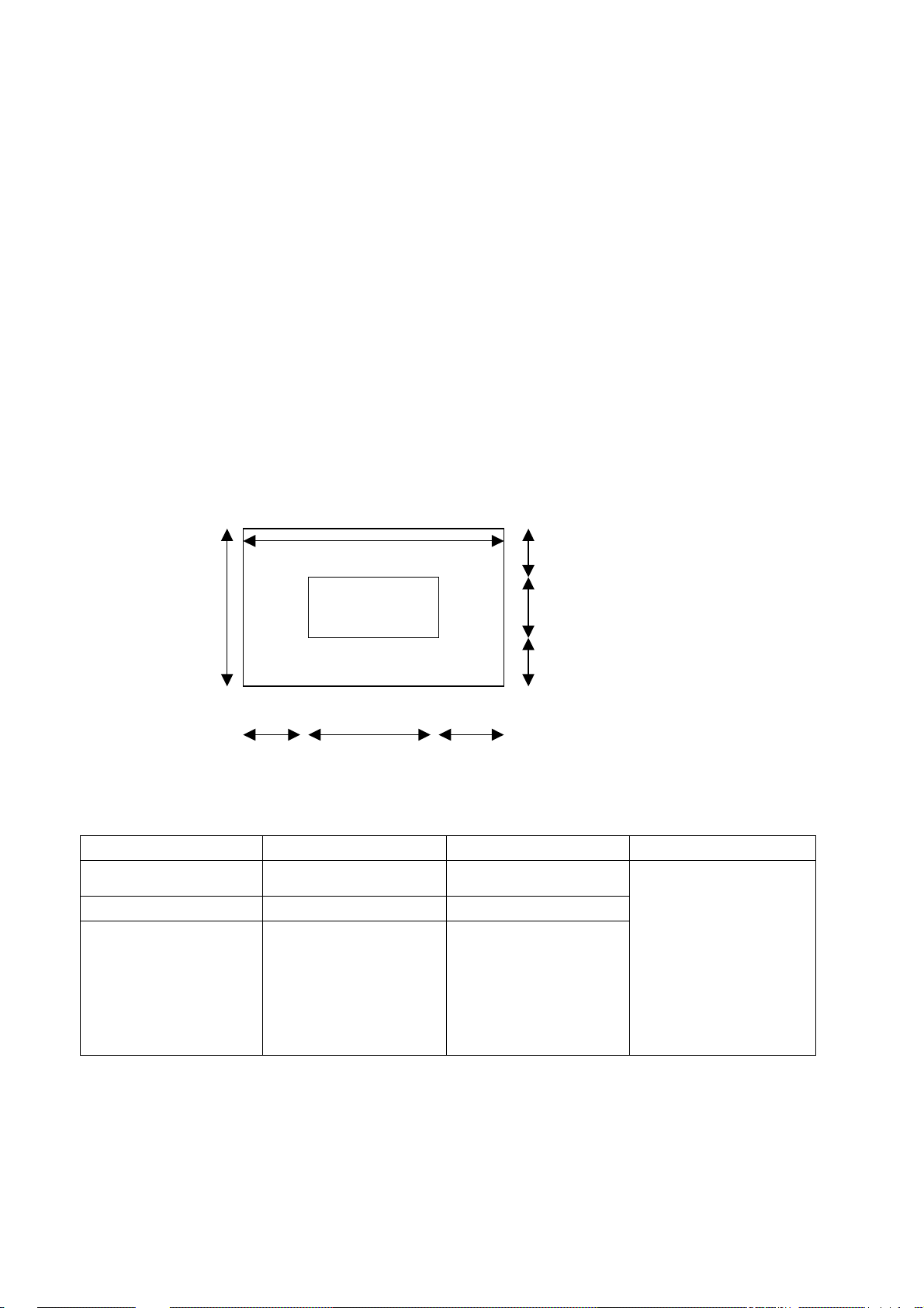
2.1,Model PS-42D8:
There may appear three kinds of defective points for this model as shown in Fig.1, i.e.,
bright spot (remain bright); dark spot (non-illuminating); flickering spot (continuously
flickering). However they should not exceed the specification as in table 1. Otherwise the
product shall be deemed as sub-standard.
Zone B
Zone A
W/4 W/2
Figure 1 Defective Points
Table 1 Criterion for Three Kinds of Defective Points
W/4
H/4
H/2
H/4
Kind Area A Area B Remark
Dark spots No more than 2 No more than 8
Bright spot No more than 1 No more than 2
Flickering spot No more than 1 No more than 2
Total number of
defective points in A
and B shall not
exceed 8. The
distance between
two defective points
shall not be shorter
than 15mm.
3
Page 5
2.Method of Debugging
V
f
1. Adjustment for MS42K8 excludes 3.1and 3.2
2.Adjustment and calibration Equipment
PM5518(Video signal generator), K-7253(VGA signal generator),CA100 (White
Balancer)
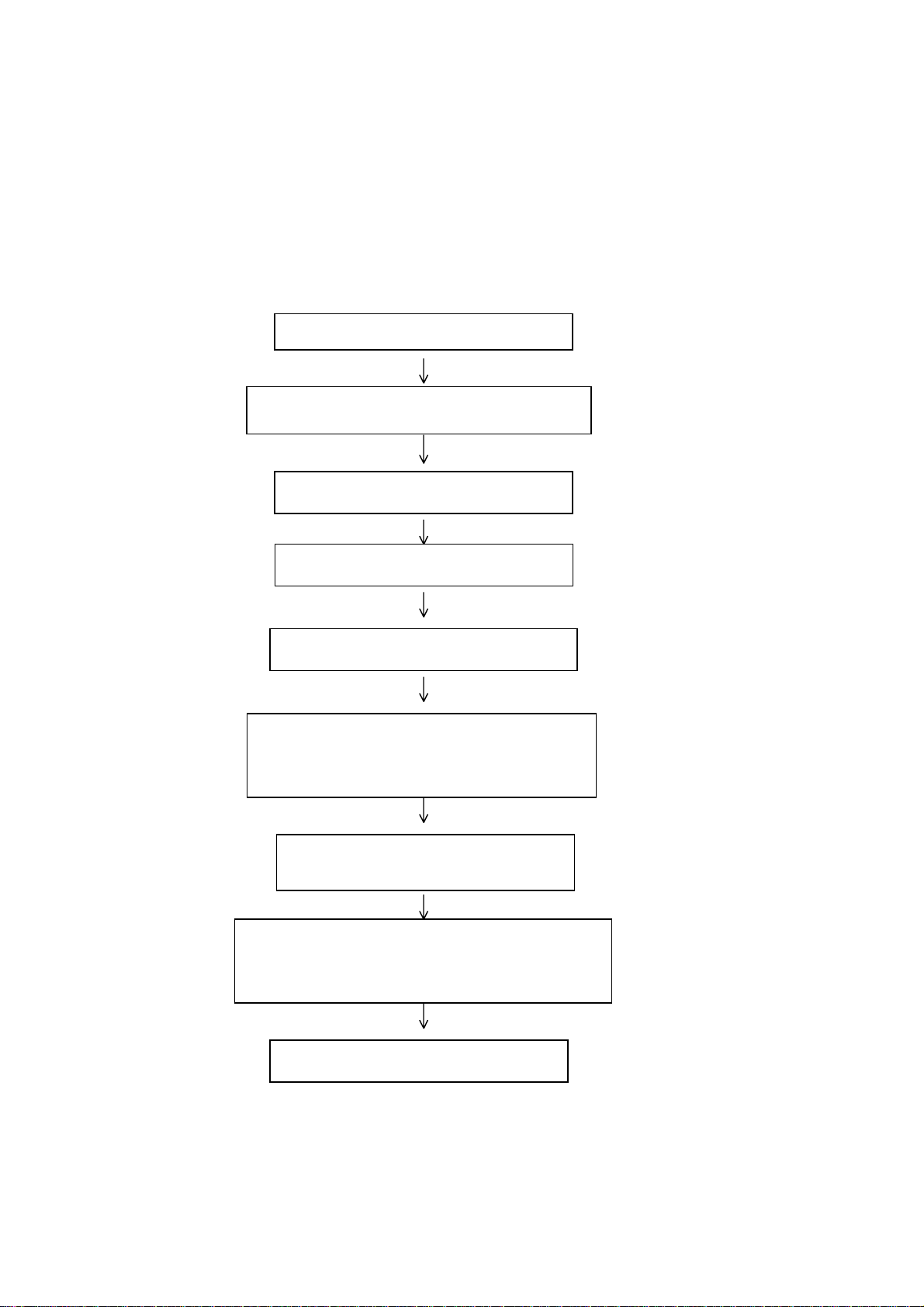
3.Flow process of Adjustment and calibration
For flow process of Adjustment and calibration, see Figure 1
Connect to central signal source, check if various T
functions (station skipping, analog control etc), check i
the output of earphone and speaker is normal
Input VGA sign al (one format) and check if display is
normal in the state of PC and various functions
(analog control, line/field center etc.)
Check if DDC has been FLASH written.
Production of CPU board and AV or TV board on the
line.
Check CPU board
Check AV or TV board
Combined test for general assembly
Input AV/S, HDTV signal and check various
functions under terminals
Check accessories and then packing
Figure 1 Flow process
of Adjustment and
calibration
4
Page 6

4.AV/TV Board adjustment
Adjust the potential meter VR12 on the power supply board, measure the test point
TP1(12VAMP) on the AV/TV board and set the reading at 15±0.05 V.
5. CPU board adjustment
Connect CPU board, push button board and AV or TV board, put power on, and
observe if the display is normal.
Method to enter the factory menu: Continuously push “ VOL+”“Mute” “ Video” keys
to enter the factory menu. Push the “ENTER” key to select different adjustment item when
the first line of each adjustment item is in high brightness. Push “ENTER” key after the
mode is selected with VGA and DV1 input and select three color temperatures
6500K,9300K,and 12000K. Push “MENU” to quit the factory menu.
5.1 EPROM initialization
Enter the first page of factory menu, push “ENTER” key after the selection of Clear
EEPROM, and shut off the power supply after the appearance of “OK”.
5.2 VGA channel adjustment
5.2.1 VGA channel mode preset
Input VGA signal of K-7253(PATTERN 5:Final Test),select TIME301(640*350/70Hz),
push”AUTO”key to automatically set the picture full screen. Likewise, automatically
adjustTIME302(720*400/70Hz), TIME303(640*480/60Hz), TIME311(800*600/60Hz),
TIME313(1024*768/60Hz),TIME315(640*480/75Hz),TIME316(800*600/75Hz),TIME317(10
24*768/75Hz),TIME319(1280*1024/75Hz) ,and TIME339(1280*1024/60Hz ) respectiv ely.
5.2.2 AGC adjustment of VGA channel
Adjust ADC-gain to 15
5.2.3 White balance adjustment of VGA channel
Input K-7253 TIME303(640*480/60Hz),PATTERN471,and the signal of 8 grades of
grey density. Enter the adjustm ent menu of white balance. Use the white balancer to adjust
second and seventh grades.
Select mode to be 6500K,adjust offset_R, offset_G, offset_B, so that the second grade
color coordinates are 313,329 and the brightness about 2 nit. Adjust gain_R, gain_G,
gain_B so that seventh grade color coordinates are 313,329. Adjust offset_R, offset_G,
offset_B and g ain_R, gain_G, gain_B,again and again unti l tw o g rads of gr ey density are all
set to 313,329.
Select mode to be 9300K,adjust off set_R, offset_G, offset_B,so that the second grade
color coordinates are 285,290 and the brightness about 2 nit. Adjust gain_R, gain_G,
gain_B so that seventh grade color coordinates are 285, 290. Adjust offset_R, offset_G,
offset_B and gain_R, gain_G, gain_B, again and again until two grads grey density are all
set to 285,290.
Select mode to be 12000K.Adjust o ffset _R, of fset_G , of fset_B,so th at the second g rade
color coordinates are 270,283 and the brightness to be about 2 nit. Adjust gain_R, gain_G,
gain_B, so that the sev enth gr ade color coor dinates ar e 270, 283. Adjust offset_R, of fset _G,
offset_B and gain_R, gain_G, gain_B, again and again until two grads grey density are all
set to 270,283.
Note: The value of gain_R, gain_G, gain_B should not exceed 128, and at least one
of them must be guaranteed to be 128.
5.3 AV/TV channel adjustment
5
Page 7

5.3.1 VCO, OPTION, sub-brightness, and sub-contrast adjustment
Input the AV color bar signal (PM5518 COLOUR BAR 100%)to VIDEO terminal, enter
the first page of factory page, select auto color, push “ENTER” key. Two seconds later, OK
appears and shows th e VCD a djust ment i s o ver. Set the value of op tion t o 9, s-br ig ht to 15 0,
s-contrast to 130,max-volume :PS42K8 and 14/MS42K8 to 66.
Enter the adjustment page of VPC3230, adjust the data of the page to be 0,1,3,3,0,1,9
from top to bottom.
5.3.2 White balance adjustment of AVTV channel
Input AV signal (PM 5518, 8 grades of grey density), enter the adjustment menu of
white balance. Use the white balancer to adjust second and seventh grades.
Adjust offset_R, offset_G, offset_B, so that the second grade color coordinates are 255,
245, and the brightness to be 2.5 nit. Fix gain_B to 128,adjust gain_R,gain_G,,so that the
seventh grade color coordinates are 288, 285, Adjust offset_R, offset_G, offset_B and
gain_R, gain_G, again and again until two grads grey density are all set to the specified
value.
5.4 White balance adjustment of D4 channel
Input YPbPr signal o f K-7253 to D4- terminal ,input eig ht grades of grey density sig nal of
TIME380(480i)PATTERN471, adjust s-bright to 120,S-contrast to 130. Enter the
adjustment menu of white balance,adjust second grade with balancer. Adjust offset_R,
offset_G, offset_B so that the second grade color coordinates are 255,245 and the
brightness about 2.5 nit.
Input eight grades of grey density signal of mode T IME392(480p),TIME394(720p)and
TIME396(1080i)separately. Repeat above operation, so that the second grade color
coordinates are 255,245 and the brightness about 2.5 nit.
6. Functional inspection
6.1 TV function
Enter the search menu auto search, connect the central signal source to RF-TV
terminal, check if there is station skipping.
6.2 BS connector
Input BS satellite signal to RF-BS terminal,check BS-5,BS-7,BS-11,if the picture and
sound of three channels are normal. Use oscillograph to check if the terminal output is
normal (Bit Stream is 1 Vpp data flow; Detection Out is 1.34 Vpp detective wave signal).
6.3 AV/S,D4 terminal
Input AV/S, HDTV signal, check if they are normal.
6.4 VGA connector
Insert VGA signal connector, input signal with format 640x480@60 Hz VGA, check if
the display is normal. If there is interfere in picture, push the adjustment key on the remote
control one more time and check if the display is normal.
6.5 Sound channel inspection
Check if the speaker output of each channel is normal.
6.6 For factory preset, see table. 1
6
Page 8

Table 1. For factory preset
Item Factory
Preset
Picture
mode
Sound
mode
N/R WEAK SRS ON
SCREEN 16:9 BALANCE ON
NATURE OSD
NEWS VGA color
Item Factory
Preset
Japanese BS POWER ASSOCIATE
language
9300 AV1/DECODER AV
temperature
Item Factory
Preset
3. Introduction of working principle of Plasma TV PS-42K8
The plane screen technology of Plasma is the latest state of art, and it is the best
selection of h igh qua lity p ictu re an d big pu re flat scree n. Th e pla sma dis play PD P is a kind
of display device by means of gas discharging. This kind of screen adopts plasma tube as
light emitting unit. PDP panel consists of many pixel units (plasma tube), such as the
screen of the 42” PDP sold currently, which consists of 852*480 pixel units. Each pixel unit
includes three sub-pixel units. Each pixel unit is a plasma tube, which displays red, green
and blue separately. Each chamber to which each plasma tube co rresponds is filled with
neon or xenon gas. When high voltage is applied between the poles of plasma tubes, the
gas sealed in the chamber of plasma tube between two layers of glass of radiates
ultraviolet light, which in turn excites the fluorescence powder of three base color - red,
green and blue - on the plane screen r adiates visibl e light. Each plasma t ube, as a pixel uni t,
produces different pictures with different color and grey density through various
combinations of its changes in b rightness and color, which is similar to the light emission of
CRT. Compared with other displays, the plasma technology has apparent differences. Its
construction and composition is ahead of other technologies. The working principal is
similar to normal fluorescent lamp. The color picture of the TV is formed of the light
emissions by each pixel unit of fluorescent powder. Thus, the picture looks bright, fresh,
clean and well focused. Besides, The most outstan ding characteri stic of plasm a TV is that it
can be made super thin, and it’s very easy to make the screen as large as over 40 inches
while the thickness is less than 100 mm. (The thickness of our PS-42K8 is 79mm only,
which is the thinnest in the market)
1. For the working principle and process flow of PS42K8, see block diagram
of complete TV set. The signal flow process is described briefly as follows:
By way of TUNA01, the RF signal of sa tellite TV, BS-RF produces color full TV signal
TV-BS and audio frequency signal BS-R/L. By way of TUNA02, the RF signal of broadcast
TV produces full col or TV signal TV-IN2 and second IF sound signal SIF. The VIDEO signal
selected by PI50V330(NA07)through TV-BS and TV-IN2 is sent to video decoder
VPC3230(U29). Video signals AV,SVHS and YcbCr are sent to U29 respectively. After the
selection of above four video signals, one route is as AV OUT, another route is for color
decode. Then the signal in the format of ITU-R656 of 8 bits is sent to FLI2310(U13)for
progressive processing.
D4 is sent to MST9883(U30), where the signal undergoes digit to analog conversion
7
Page 9

and then it is also sent to U13 in YUV format of 24bit.
24bit RGB signal is output and sent to main processing IC JAG-ASM(U12) after the
above two routes of signal are processed in matrix , color density, and tint in U13.. Another
route of RGB signal of computer VGA is also sent to U12, where two routes of signal are
subject to selection and processing for picture format. One route RGB signal of VGA
undergoes A/D conversion before being subject to selection and digit display processing
together with another route of signal, including OSD, GAMMA calibration, brightness and
contrast processing. These signals are changed into the format of 1024*768. The above
RGB signal of 24 bit is output to LVDS converter DS90C385(U31)of; where it is converted
into four pairs of low voltage differential signal acceptable for PDP screen. Then, the signal
is sent to PDP screen for picture display.
The audio R/L of left and right sound channels D4,YCbCr and BS undergoes selection
and is then sent to MSP3420(NA04) . AV,SVHS and R/L of VGA are sent to N AQ04.I n NA0 4,
the second sound IF( SIF) is demodulated into audio signal together with other four routes
of sound signal being switched for selection. The selected R/L after the processing in
volume and sound effect is then output. One route MONO sound is for AV OUT, the other
route is sent to M62494(NA08)of SRS sound field processor for SRS processing. The
signal, after sound power amplification by TPA3001(NA10,NA11), is for driving the speaker.
BS tuner outputs other route BIT/DET. The power is supplied by power supply board on
PDP screen and then transformed into different required power supplies.
8
Page 10
2.BLOCK DIAGRAM
VGA
BS-RF
RF
Y
C
AV
YCbCr
AV-V OUT
D4
BIT/DET
TUNA01
TUNA02
SIF
VPC3230
V
U30
ADC
MST9883
TV-BS
TV-IN2
NA07
PI5V330
TV
VIDEO DECODER
U29
RGB
ITU-R656
8bit
24bit
YUV
U13
DEINTER
LACER
FLI2310
U14
SDRAM
2
I C BUS
U3
EEPROM
RGB
24bit
U12
SCALER
JAG-ASM
U19
SDRAM
U20
SDRAM
U2
MICRO-CONTRLER
TSC80251G2D
RGB
24bit
U31
LVDS
DRIVER
DS90C385MTD
KEY BOARD
U4
FLASHMEMORY
IR
PANEL
SIF
D4
YCbCr
BS
VGA
AV
S
AV-MONO OUT
HEF4052
NA03
MONO
NA04
AUDIO
PROCESSOR
MSP3420
R/L
NA08
SRS 3D STEREO
CONTROLLER
M62494
R/L
NA10
NA11
AUDIO
AMPLIFIER
TAP3001
9
R/L
SPEAKER
Page 11
4.IC BLOCK
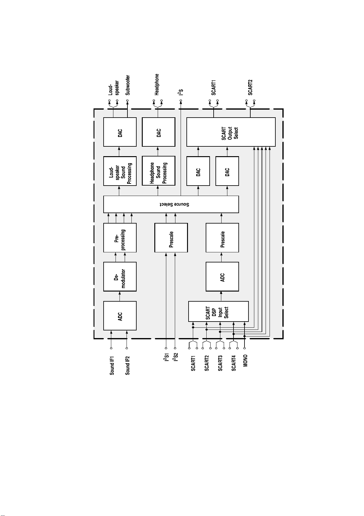
1. MSP3420
10
Page 12
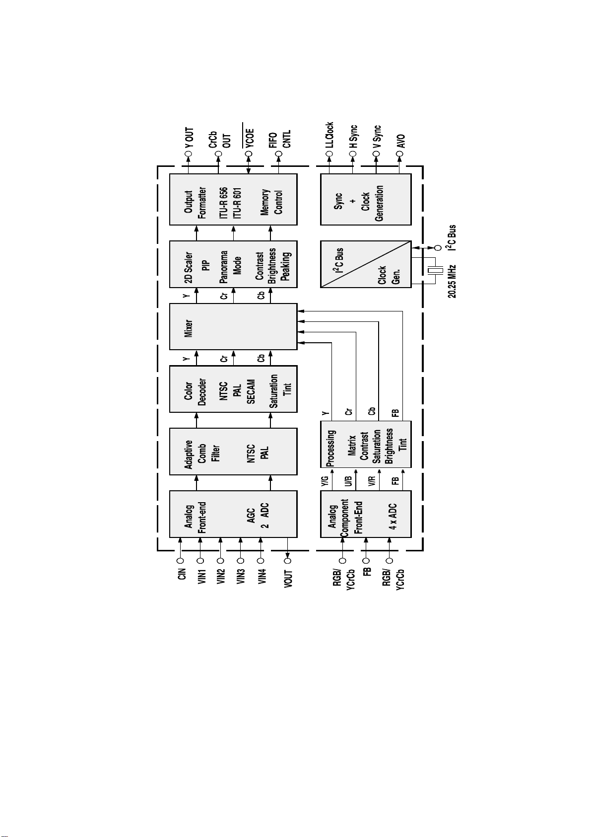
2.VPC3230
11
Page 13
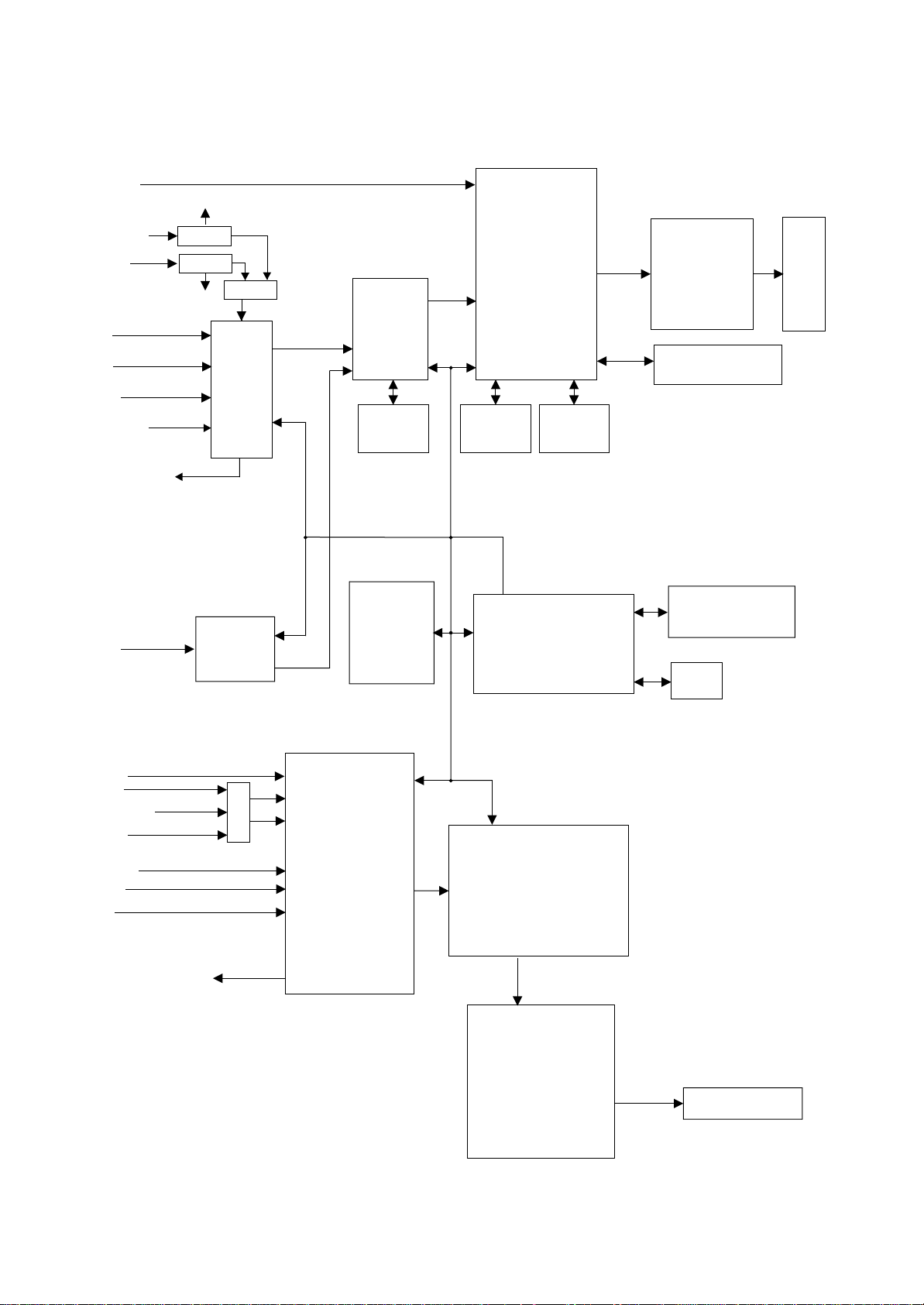
3. JAG-ASM
12
Page 14

BOARD
SOUND BOX PART
POWER FILTER
667-PS42K8-40
ADUIO-VIDEO PROCESSOR BOARD
POWER BOARD
PS42K8 WIRING DIAGRAM
335-42001-00
PANEL
CPU BOARD
BOARD
LOGIC CIRCUIT
667-MS42K8-56
KEYSETS
667-PS42K8-05
Page 15

5.Distribution of the Circuit Board of Different Screens and their
Functions
42SD(Type:S42 SD-YD04,Code No:335-42001-00)
Y driving
Power supply board
X driving
Logic board
Addressing circuit
Parts
designation
Power supply
board
Logic board
Addressing circuit
X driving
YX driving
Function
Provide power for the operation of complete TV set
Convert the LVDS signal from the processing board into the one displayable by
screen
Addressing circuit for screen display, directly driving the address electrode on
the screen (Vertical electrode, totally 852X3electrode)
X electrode(horizontal common holding electrode)driving circuit
Y electrode(horizontal scanning, holding electrodes, total 480 electrode)driving
circuit
14
Page 16

8.PCB parts and number
Parts name Parts number Main parts and number
U12 JAG-ASM (353-0JAG0-00)
U13 FLI2310 (353-23100-00)
U29 VPC3230D (353-32300-80)
CPU board 667-MS42K8-56
video frequency
processor boards
Remote parts 301-UPS42D8-09
key-press board
parts
Power filter board 667-PS42D8-51
667-PS42K8-40
667-PS42K8-05
U30 MST9883B (353-98830-10)
U31 DS90C385MTD (353-03850-20)
U2 TSC80251G2D (353-80251-10)U4
AT49F002NT (352-49002-70)
NA04 MSP3420G-Q (353-34200-10)
NA08 M62494FP (353-62494-20)
NA10 NA11 TPA3001 (353-30010-10)
15
Page 17

n
9.Diagram of Normal Trouble Shooting
b
d
r
N
k
N
r
N
d
1. “Three no”, i.e., no raster, no picture and not sound:
If power indication lamp is lit
yes no
normal
Short circuit the pin 8 (PS-ON)
of X709 to the ground, the
normal abnormal normal abnormal
JI
501abno
rmal
Normal abnormal
Check supply,
crystal oscillation
for N501andN601
normal
Check supply fo
102,N204,N302,N403,crystal
oscillation and bus line
Note:Power supply for PDP is pr ovided with over current and over voltage protection functions.
If there is over current or over voltage, this protection will function and no output.
Check powe
esp. D3.3V
Pull out
X709 chec
Short
circuit in
Check N501and
601
Power boar
Three no
check5V-STBY
Cutoff the connection
etween power board
and signal process,
check5V-STB
Cutoff the connection
x2 between main boar
and video process.
Board,then determine
which board is
abnormal
Power board
problem
16
Page 18

2. There is sound but no picture:
N
f
d
d
d
N
d
yes no
Check if no image for all other
no yes
normal
Normal abnormal
Normal abnormal
NOTE:
501 and
peripheral
channels
Change into 4
check
program
With sound but no picture
If there is interface for switch on
If oscilloscope is
ready,first measure
the wave form o
signal X60
abnormal
Check input signal of N601an
power supply
601damage
Check N501and the circuit
Pull X604,X709,short circuit pin 8 of
X709 to the ground,set logic boar
switch to self check signal,see if the
screen appears white when switched on
Screen damage
of output part
Setting up for the self check of the screen:
For 42”SD screen (S42SD-YD04):Push down 2 and 4 and push up 3 of
SW2001on the logic board;
For 50”HD screen (S50HW-XD02):Push down 1 a nd 4 and push up 2, 3, 5, 6 of
SW2001on the logic board;
Please make sure resume it to the original status when the check is over.
17
Page 19

3. There is picture but not sound.
p
p
m
put
There is picture but no sound
If there is output from XA04of sound power amplification board
No
Yes
Measure if there is signal in pin 2
of sound
ower amplf.2
yes no
Sound power ampl. or other peripheral circuit have problem. Check
power supply,if SHUTDOWN pin control is normal and if output
short circuited or other problems that cause protection to work.
yes no
MSP3440 or other peripheral
circuit have
roblen
4. A certain channel is abnormal
1) AV/YCRCB no picture
If Check U29 pin72
(S-VIDEO),pin73(VIDEO) and
pin5,75 (YCRCB)signal input
yes no
Check U29
pin27,31~34,37~40
output and ITU-R 656
no yes
Check U29
Check RP3~RP9 and U13
FLI2310 out
no yes
Check U13 FLI2310 Check U12
Sound box damaged
Measure if the sound input of the
present channel corresponding to
NM2 is normal
Check different levels of
circuit following input audio
signal channel
Check U29
18
Page 20

2) D4 no picture
Check U30 pin48(Y) and pin49 (SOG)
yes no
yes no
Check RP36~RP41,RP141
and U30
Check RP3~RP9 and U13
FLI2310
Check D4 to U30
Check U30
否 yes
Check U13 FLI2310
Check U12
19
Page 21

4) TV no picture
p
T
N
f
normal no picture
Input an AV signal to see if AV
channel is normal
normal abnormal
normal abnormal
.
Check power supply for
TUNER1, bus line and
video output circuit.
normal normal abnormal normal abnormal
normal
Input circuit of
N102 or
interface has
problem
N204 and its
eripheral
circuits
have
Take out dual picture and set the other picture
to TV, to see if this picture is normal.
Check output signal of
N102(line/field
synchronous, clk, PEN etc.)
Check if output signals
of N204(line/field
synch. CLK, PEN)are
normal
Check
102and its
peripheral
TUNER
Peripheral circuits
of N501 V POR
have problem
Input an AV signal to see if
the AV of dual picture is
normal.
If input VGAsignal is
If voltage of N702
is normal
If the connection
between boards is
normal
Check in the
sequence o
2
20
Page 22

f
f
3) VGA No Picture
normal abnormal yes no
normal abnormal
5. Abnormal picture :
Measure the input line/field synch.
signal of 81 and 82 of N403
Check N403
and its
peripheral
Peculiar color, which may be caused by the follow ing phenomena:
A certain differential wire pair of LVDS (RX0+/-,RX1+/-,RX2+/-,RX3+/-) is abnormal,
which may lead to lack of color ( it’s not a complete loss of color);
Failure with re sistor row s R550~ R555,which may lead to loss of correspo nding co lor from
the gray degree corresponding to the picture of all channels. Through self signal check by
PW181, the failure is still there.
Failure with re sistor row s R41 9, R421, R425, R427, R43 1, R432,wh ich may le ad to l oss of
corresponding color from the gray degree corresponding to the picture of channels
VGA/YPRPB/DVI.
Failure with re sistor row s R41 5, R418, R422, R424, R42 9, R430,wh ich may le ad to l oss of
corresponding color from the gray degree corresponding to the picture of channel DVI.
Failure with resistor rows R342, R343, R344, R345,which may lead to loss of
corresponding color from the gray degree corresponding to the picture of sub-channels
TV/AV/YCRCB, or lead to abnormal brightness.
Failure with resistor rows R207, R208, R209, R210, R211, R212 or R145, R146, R147,
R148,which may lead t o loss of corresp onding color from the gray degree corresponding
to the picture of main channels TV/AV , or lead to abnormal brightness.
If input YPRPB signal is normal
yes no
If the mode of VGA (lower right corner
of screen OSD) identifiable
Input interface circuit has
problem
Check N402
and its
peripheral
Check N403 and its
peripheral,especially its
output signals (CLK,
line/field synch. and
enable etc.)
If the two TV pictures are
normal
Check input
circuit o
GPORT o
N501
21
Page 23

Bad connection between N203 and N204, which may also lead to abnormal picture
(E)
(F)
(G)
(column bar like) in main channel TV/AV.
Abnormal picture vertically or horizontally (bar like): Abnormal in complete line extendi ng all t h e
way from up downward on the screen of stand definition TV setr; abnormal vertically on half
screen of high definition TV set. They may be caused by the damage of the address BUFFER
module that directly corresponds to its position, or may be caused by the damage of the
connection wire that directly corresponds to the position of the screen. The horizontal bar like
abnormality is also related to the Y driving circuit that corresponds di rectly to its position. To
judge these phenomena, It’s possible to check it by setting the screen to the status of self
check as explained above
No brightness in the square block area: Normally it’s caused by the damage of the address
BUFFER module that directly corresponds to its position, or may be caused by the damage of
the connection wire that directly corresponds to the position of the screen. To judge these
phenomena, It’ s possible t o check it by settin g the sc reen to the stat e of se lf chec k as explaine d
above
Diagnosis for Plasma Screen of PS42D8
And Maintenance of the Functions of Various Modules on Screen
As shown in the figure below, PDP screen can be divided into power supply board, X driving board, Y
driving board, logic board, logic BUFFER board (E, F, G), Y BUFFER board ( upper and lower), COF
etc.:
Y BUFFER(up)
Ydriver board
Y BUFFER(down)
Logic
BUFFER
Logic
BUFFER
Power supply board
Logic board
X driver board
Logic
BUFFER
* Power supply board: to supply power for the screen, other functional modules on the screen,
our own main board, and video frequency processing board.
COF(7 blocks)
22
Page 24

* X driving board: to produce and provide driving signal for X electrode according to the time
sequence signal sent from logic board.
* Y driving board: to produce and provide driving signal for Y electrode according to the time
sequence signal sent from logic board.
*Logic board: to process the image signal sent from the main board, to produce addressing
signal and to provide driving signal for X and Y driving boards.
*Logic BUFFER board (E, F): To convert the data signal and control signal sent from the logic
board into the signals required by COF
*Y BUFFER board (Upper,Lower): to transmit the scanning signal from the Y driv ing board to
the screen, which is divided into upper and lower parts.
*COF:to convert the signal sent from the logic BUFFER board into the address signal used by
the screen.
II. Trouble diagnosis:
1. The screen is not bright:
a. Check to see if the power supply plug from the pow er filter board to the power supply board is
well inserted into the socket. If not, plug it in.
b. Check if the fuse on the power supply board is blown up. If yes, replace it for a good one.
c. Remove our main board and the video frequency processing board, ground the pin 4
POWER_ON/OFF of socket CN802 of the power supply board,
Weld drop
and then push the slide s wit ch S W2001 on the log ic board to t he int ern al mo des (1, 3 up a nd 2,
4 down) from external modes (1, 2, 4 up and 3down)
23
Page 25

SW200
1
Switch the power on and see if the screen is lit. If the screen can give a normal and
completely white field signal, then the problem lies in our main board or video frequency
processing board, which will be dealt with separat ely.
d. If the screen is not lit, then first replace the power supply board to see if the problem is
solved.
e. If the problem remains after the power supply board is replaced, then the problem lies in the
screen. Replace the entire screen for treatment.
2. There appears on the screen a line or several unlit lines.
Check if the socket bet ween Y driving board an d Y BUF FER is pl ugged we ll. If not, pl ug it we ll. If
yes then replace Y BUFFER ( upper, lower) in respect to the upper , l ower part of the dark line on
the screen.
3. There appear on the screen one or several horizontal lines that are much brighter than the
remaining horizontal lines at the edge:
Check if the socket bet ween Y driving board an d Y BUF FER is pl ugged we ll. If not, pl ug it we ll. If
yes then replace Y BUFFER ( upper, lower) in respect to the upper , l ower part of the dark line on
the screen.
4. There appear on the screen one vertical unlit line or a vertical entirely unlit block
24
Page 26

a. If it’s one v ert ical unlit line, then COF has problem.
b. If it’s a vertical entirely unlit block, then first check if the connection socket between COF and
logic BUFFER has proble m. If not, check if the con nect ion socket bet ween t he logic BU FFER
and the logic board is normal. If yes, replace the logic BUFFER. Finally, if the problem still
remains when the replacement is over, then replace the logic board.
5. There appears on the screen a mono color signal an d one or sev eral vert ical br ight lin es of oth er
colors:
a. If it’s a vertical bright line of other colors, then the problem lies with COF or t he screen.
b. If it’s an entire vertical block of other colors, then first check to see if the connection socket
between COF and logice BUFFER has problem. If no problem, check if the connection
socket between the lo gic BU FFE R and t he log ic b oard is nor mal. If it’ s n or mal , t hen replace
the logic BUFFER. If the problem still remains after the replacem ent, then replace the logic
board. Finally if the problem is still there, t hen the problem lies with COF.
6. There appear on the screen abnormal bright spots or blocks that are different from what’s
described above:
a. Check if the connection socket between COF and logic BUFFER board has been well
plugged.
b. Replace the logic BUFFER board. If it’s not solved then replace logic board. If the problem
still remains, then it’s the problem with COF.
25
Page 27

Page 28

Page 29

Page 30

Page 31

Page 32

Page 33

Page 34

Page 35

Page 36

Page 37

Page 38

Page 39

Page 40

Page 41

 Loading...