

Page 1
PDP TELEVISION
PS-32HU35
Page 2

CONTENTS
Safety precautions………………………………………………………………………..…
Alignment instructions …………………………….…….…………………………………
Working principle analysis of the unit……………………………….………….………….
Block diagram…………………………………..………………………………….…………
IC block diagram………………………………………………………………………..……
Wiring diagram …………………………………………………………………………….
Troubleshooting guide ………………………………………………………………..……
Schematic diagram…………………………………………………………………………
APPENDIX-A: Assembly list
APPENDIX-B: Exploded View
1
3
6
7
8
13
14
17
Page 3

Attention: This service manual is only for service personnel to take reference with. Before
servicing please read the following points carefully.
Safety precautions
Please read the “Points for attention for the Maintenance & Repair of PDP” and “Criterion for
Identifying the Defects on Screen” as below, before inspecting and adjusting the TV set.
1. “Points for attention for the Maintenance & Repair of PDP”
To avoid possible danger, damage or jeopardy to health and to prevent PDP screen from new
damage, the maintenance people must read the following carefully. If they ignore the following
warnings, there will be deathful risks:
1.1 Screens vary from one model to another and therefore not interchangeable. Be sure to use the
same type of screen in the replacement.
1.2 The operation voltage is approximately 350v for PDP module (including screen, driving circuit,
logic circuit and power module). If you want to conduct maintenance work on PDP module when the
set is in normal operation or just after the power is off, you must take proper measures to avoid
electric shock and never have direct contact or touch with the circuitry of the working module or
metal parts. That’s because within a short time relatively high voltage still remains on the capacitor
of the driving part even after the power is off. Make sure to begin relevant maintenance operation at
least one minute after the power is off.
1.3 Don’t apply on the module any power supply that is higher than the specification. If the power
supply used deviates from the value given in the specification, there might be a possibility of leading
to fire or damage to the module.
1.4 Never have operation or mounting work under unsuitable environment such as areas in the
vicinity of water (bath room, laundry, water chute of kitchen), sources of fire, heat-radiation parts or
direct exposure to sunlight. Otherwise there will be kickbacks.
1.5 In case foreign substances such as water, liquid, metal slices or others fall into the module
carelessly power must be cut off immediately. Keep the module as it is and do not move anything on
the module. Otherwise it might be possible to contact the high voltage or cause shock short circuit
so that it may lead to fire or electric shock.
1.6 If there is smoke, abnormal smell or sound from the module, please cut the power off
immediately. Likewise in case the screen doesn’t work when the power is on or during the operation,
please also cut off the power at once. No more operation in this case.
1.7 Do not remove or plug its connection wire when the module is in operation or right after the
power is off. That’s because there remains a relatively high voltage on the capacitor of the driving
circuit. If there is a need to remove or plug in the connection wire, please wait at least one minute
after the power is off.
1.8 Considering the module has a glass faceplate, please avoid extrusion by external force lest it
should cause glass breakage that may get people injured. Two people are needed in cooperation to
move this module lest contingency takes place.
1.9 The complete TV set is designed on the basis of full consideration of thermal dissipation by
convection, with the round hole on the top for heat emission. To avoid overheat, please do not have
any covering on the hole during normal operation and never put it in the place where the space is
1
Page 4
narrow and in bad ventilation.
1.10 There are quite a number of circuits in PDP that are integrated ones. Please be on guard
against static electricity. During maintenance operation be sure to cover yourself with anti-static bag
and before operation make sure to have it sufficiently grounded.
1.11 There are a big number of connection wires distributed around the screen. Please take care
not to touch or scuff them during maintenance or removing the screen, because once they are
damaged the screen will fail to work and it’s not possible to repair it.
If the connection wires, connectors or components fixed by the thermotropic glue need to disengage
when service, please soak the thermotropic glue into the alcohol and then pull them out in case of
damage.
1.12 Connector for the circuit board of the screen part is relatively fine and delicate. Please take
care in the replacement operation lest it should get damaged.
1.13 Special care must be taken during transportation and handling because strenuous vibration
could lead to screen glass breakage or damage on the driving circuitry. Be sure to use a strong
outer case to pack it up before transportation or handling.
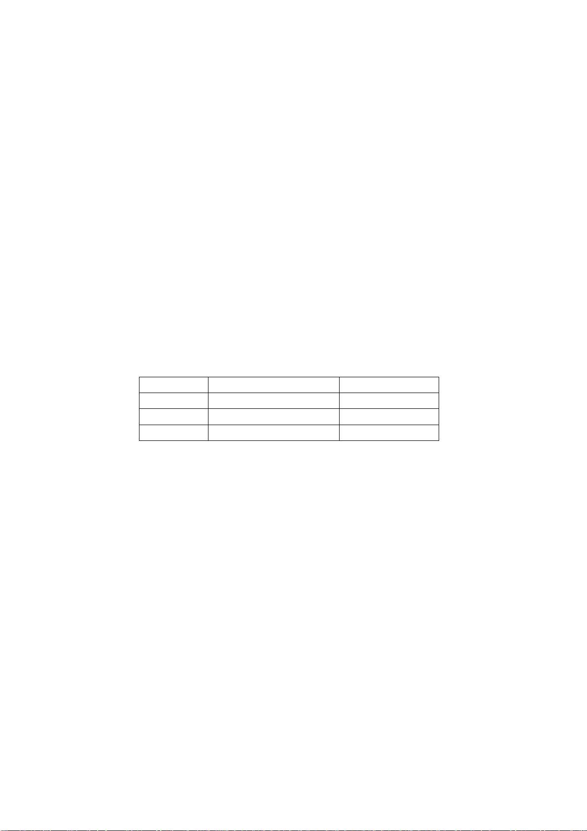
1.14 Please put it for storage in an environment in which the conditions are under control so as to
prevent the temperature and humidity from exceeding the scope stipulated in the specification. For
prolonged storage please cover it with anti-moisture bag and have them piled and stored in one
place. The environmental conditions are tabulated as below:
Temperature Scope for operation 0~50centigrade
Scope for storage -15~60centigrade
Humidity Scope for operation 20%~80%
Scope for storage 20%~80%
1.15 If a fixed picture is displayed for a long time, difference in its brightness and color may occur
compared with movable pictures. But it doesn’t show any problem and the reason is that there is
reduced density of fluorescent powder in the former. On the other hand, even if changes take place
in the picture, it can keep its brightness for a period of time (several minutes). It’s a feature inherent
with plasma and it’s not abnormal. However please try as much as possible to avoid showing a still
picture of high brightness for a long time during operation.
1.16 As a digitalized display devise, this module is provided with error diffusion technology and the
gray scale and false enhancement of contour can be displayed by reusing of sub-field. As compared
with cathode ray tube, it can be found in the moving picture that at the brim of the face of a person
there are some wrong colors.
1.17 During the display of graph (indicating the gradual change in brightness horizontally or
vertically) resulting from gray scale test it can be found that the brightness for the two adjacent
levels is uneven. This is caused by the reuse of sub-field, the display of load rectification and the
electrolysis.
1.18 The screen front plate is of glass. Please make sure that the screen has been put in place
during erection. If it is not in place before the erection begins it may lead to screen crack or
breakage.
1.19 Make sure the screw used in the mounting of the screen is of the original specs lest it should
cause damage to the screen due to mismatch. Special care should be taken not to use too long or
2
Page 5
too big screw.
1.20 Care must be taken to guard against dust during assembling or dismantling, especially to avoid
dirt from falling in between the screen and the glass lest it should harm the receiving and viewing
effect.
1.21 There is piece of insulator stuck on the rear chassis corresponding to the power supply board.
It is used to isolate the cool part from the hot part. Please take care to keep it intact lest it should
become a potential safety trouble.
1.22 In addition to plasma screen, the glass is a part of high value. It has such functions as
anti-radiation, adjustment of color temperature etc. Please handle it carefully.
Alignment instructions
1. Test equipment
PM5518 (video signal generator)
VG-848 (VGA and HDMI signal generator)
CA100 (color analyzer)
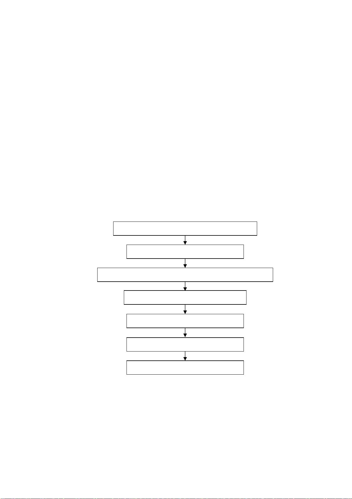
2 Alignment flow-chart
The alignment flow-chart is shown as fig-1
Check DDC, HDCP KEY, FLASH and POWER control IC
Factory initialization setup
IF channel AFT voltage of TV and AGC voltage adjustment
ADC correction of VGA and YPbPr
White balance adjustment
Fig-1 adjustment flow-chart
Performance check
Preset ex-factory
3 Unit adjustments
Connect all the boards according to wiring diagram, connect with power and observe the display.
Method for entering factory menu: press “INPUT”, “2”, “5”, ”8” and “0” in turn to enter factory
menu; press “CH+” and “CH-” to select adjustment items and press “VOL+” and “VOL-” to adjust
value items, press “MENU” repeatedly to exit.
Method for software upgrading: When software upgrading please enter factory menu first, enter
ISP item of OPTION, set ISP to 1 and you can begin to upgrade. After upgrade finished, it needs to
3
Page 6
set ISP back to 0. If the picture can’t display when upgrading, it needs to weld JB1 on the main
board. Please disconnect JB1 again after upgrading.
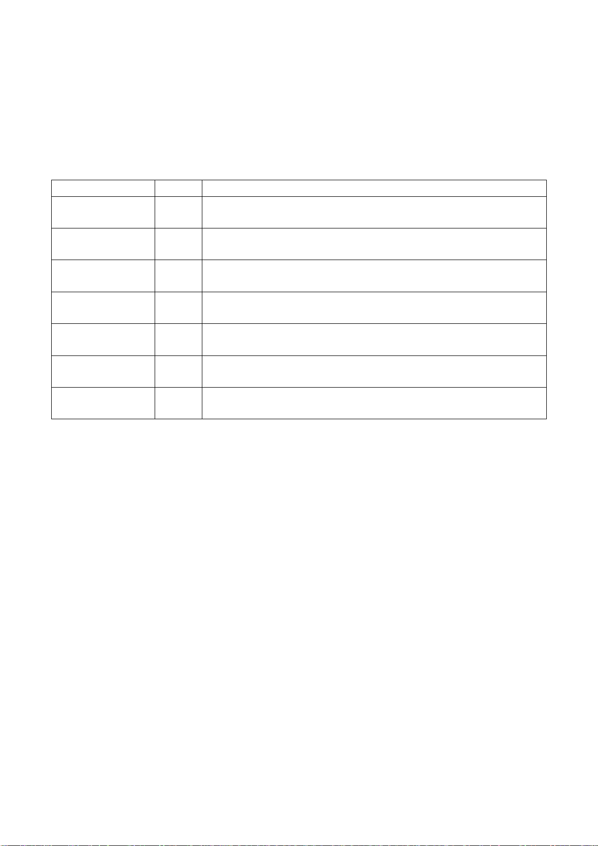
3.1 Initialization
Enter factory menu, select “OPTION”, “EEPROM” and “HOTEL OPTION” sub-menu, adjustment of
items to see table1.
Table1 sub-menu adjustment
Items Preset Introduce
HOTEL 0 ON: HOTEL OPTION of factory menu is optional
OFF: HOTEL OPTION of factory menu is not optional
LOGO 1 ON: display LOGO in no signal or turn on
OFF: no LOGO display
ADC PRESCALE 02E Software will preset the data according the unit and the data can be adjusted when
needed.
SIF PRESCALE 02E Software will preset the data according the unit and the data can be adjusted when
needed.
BACK LIGHT FF Software will preset the data according the panel and the data can be adjusted
when needed.
ALL COLOR 1 1: white balance of each channel auto offset based on the HDMI white balance
0: white balance of each channel adjust the offset base separately
EEPROM-MEMORAY
RECALL
> EEPROM Initialization (operate when EEPROM data chaos)
3.2 Adjustment for AFT voltage and AGC voltage of IF channel in TV
3.2.1 IF AFT adjustment
Enter the factory menu and set IF VCO to LL, or press “INPUT”, “2”, “5”,”8”, “1” to enter VCO
adjust mode, adjust L109 to value 2.5V of TP104 (A face), then set IF VCO to BG.
3.2.2 IF AGC adjustment
Input 184.25MHz RF signal of 60DB from RF terminal, adjust RP101 to value 3V of TP101 (A
face) and there should be no obvious snowy picture. Increase the signal to 90DBV and it should be
display normally and no obvious noise.
3.3 White balance adjustment
3.3.1 white balance adjustment of HDMI
a. Input VG-848 signal from HDMI: TIMING854(800* 600/60Hz) and eighth level gray-scale
signal of PAT920. Use color analyzer CA100 to adjust white balance.
b. Enter submenu of COLOR TEMP., Select 9300k of color temperature
c. Fixed value of B OFF, adjust R OFF and G OFF, let the color coordinate of the second level
be 285,293 and the brightness be about 3nit- 6nit. Fixed value of B GAIN, adjust R GAIN and G
GAIN, let the color coordinate of seventh level be 285,293. Adjustment R OFF, G OFF, R GAIN and
G GAIN repeatedly until the value of the two levels gray-scale be 285, 293.
3.3.2 VGA/YPBPR/AV white balance check and correction
a. Input VG-848 signal of VGA: TIMING854(800* 600/60Hz) (PATIERN:CROSS) and auto
adjust to full screen, then input PAT948 black/white signal, enter factory menu ADC ADJ, select
AUTOTUNE and wait for OK display. Input PAT920(8 gray levels), check if the white balance is
4
Page 7
normal, if not, enter COLOR TEMP menu, set ALL COLOR to 0 and fine adjust according the
method of 3.3.1 c)
b. connect VG-848 signal of YPBPR to YPBPR terminal and input TIMING972(1080i/60HZ)
100% color bar of PAT976(include black/white bar), Enter submenu of ADC ADJ, Select
AUTOTUNE and wait for OK display. Input PAT920(8 gray levels), check if the white balance is
normal, if not, set ALL COLOR to 0 and fine adjust according the method of 3.3.1 c)
c. Input AV signal(PM5518, 8 gray levels, PAL for Chinese and NTSC for America) to VIDEO 1
terminal, check if the white balance is normal, if not, set ALL COLOR to 0 and fine adjust according
the method of 3.3.1 c)
Note: it can’t set back to 1 once ALL COLOR changes to 0.
4 Performance check
4.1 TV function
Enter searching menu → auto search, connect RF-TV terminal with central signal source and check
if the picture is normal, if there are channels be skipped. Check CCD function.
4.2 AV/S, YPbPr terminals
Input AV/S, YPbPr/YCbCr HD signal, check if it is normal.
4.3 VGA terminal
Insert VGA terminal, input VGA format signal of 1024X768@60 Hz and check if the display is
normal.
4.4 HDMI terminal
Insert HDMI terminal, input signal of 1024 X 768@60 Hz signal and check if the display is normal
and the HDCP is normal.
4.5 check sound channel
Check the speaker and headphone of each channel.
4.6 other function check
Check the turn on/turn off timer, asleep timer, picture/sound mode, OSD, freeze/mute, stereo, magic
picture, ect.
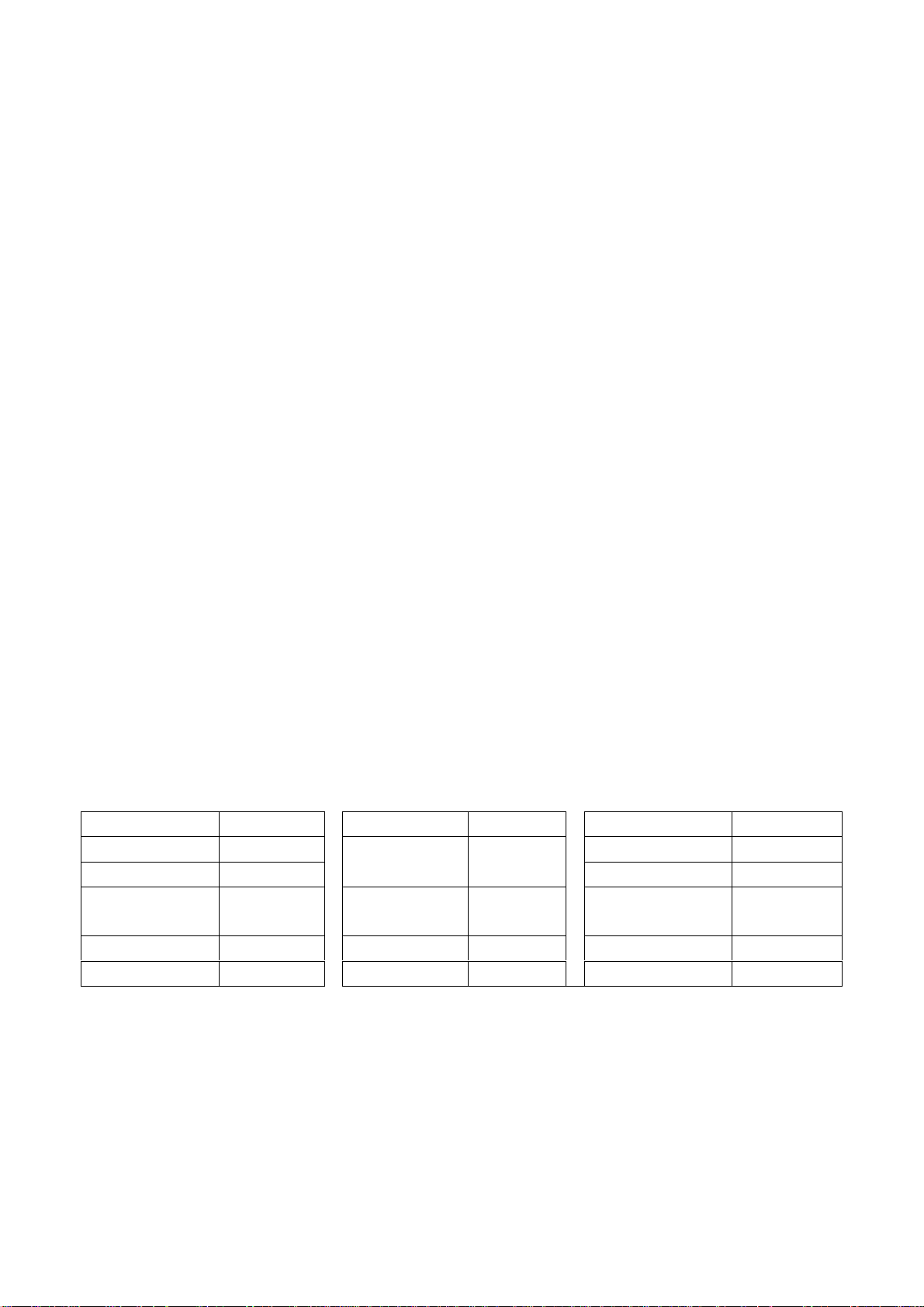
4.7 presetting before ex-factory
Item Setting Item Setting Item Setting
PICTURE MODE NAUTRAL
AUDIO MODE DK
SOUND MODE NEWS HALFTONE 50
NR WEAK DURATION 15 ANTENNA CATV
ZOOM FULL
OSD language
English /
Chinese
VGA/HDMI
color temperature
STANDARD
5
Page 8

Working principle analysis of the unit
The RF signal received by antenna will be sent to tuner TUNER101, then IF signal will be
obtained through high amplifier and mixed frequency, through pre-intermediate amplified by V101,
then it will be sent to acoustic surface-wave Z102 to do IF filter and get better IF characteristics,
then it will be sent to N101 (R2S10401) to do intermediate amplification, phase-locked loop VCO
and synchronous wave detection to get composite video signal TV-VIDEO; after pre-intermediate
amplification IF will also be sent to acoustic surface-wave Z101 to do filter at the same time, then it
will be sent to N101 to do intermediate amplification and output the second sound intermediate
frequency signal (TV-SIF).
The TV-VIDEO signal output from R2S10401 together with TV-SIF will be sent to main IC NS2
(MST9U19A). Video signals of AV1, AV2, S-VIDEO and YPbPr will be sent to MST9U19A,and
their audio signals will also be sent to MST9U19A (AV1 and YPbPr share one group of audio ports,
AV2 and S-VIDEO share one group of audio ports). The video and audio signals of VGA and HDMI
will be sent to MST9U19A, too.
The main IC NS2(MST9U19A) is a high performance and fully integrated IC, which can realize
HDMI processing, video demodulating, video switch selection, A/D and D/A conversion,
interlace/de-interlace processing, modes conversion, OSD and low-voltage differential output, ect.
And it also has functions of audio selection, processing and MCU.
The video signal via MST9U19A processing, output 4 pairs differential signal and 1 pair clock
signal for PDP panel display. AV1, AV2, S-VIDEO and video signal of TV via selecting and
processing, then output AV-OUT signal to double amplifying, then it will be sent to AV-OUT.
Audio signal via MST9U19A processing, one way will be sent to sound amplifier NV4
(R2S15102) amplifying to speaker. The other way via NV3 (LM358) amplifying, then sent to
AV-OU T.
6
Page 9
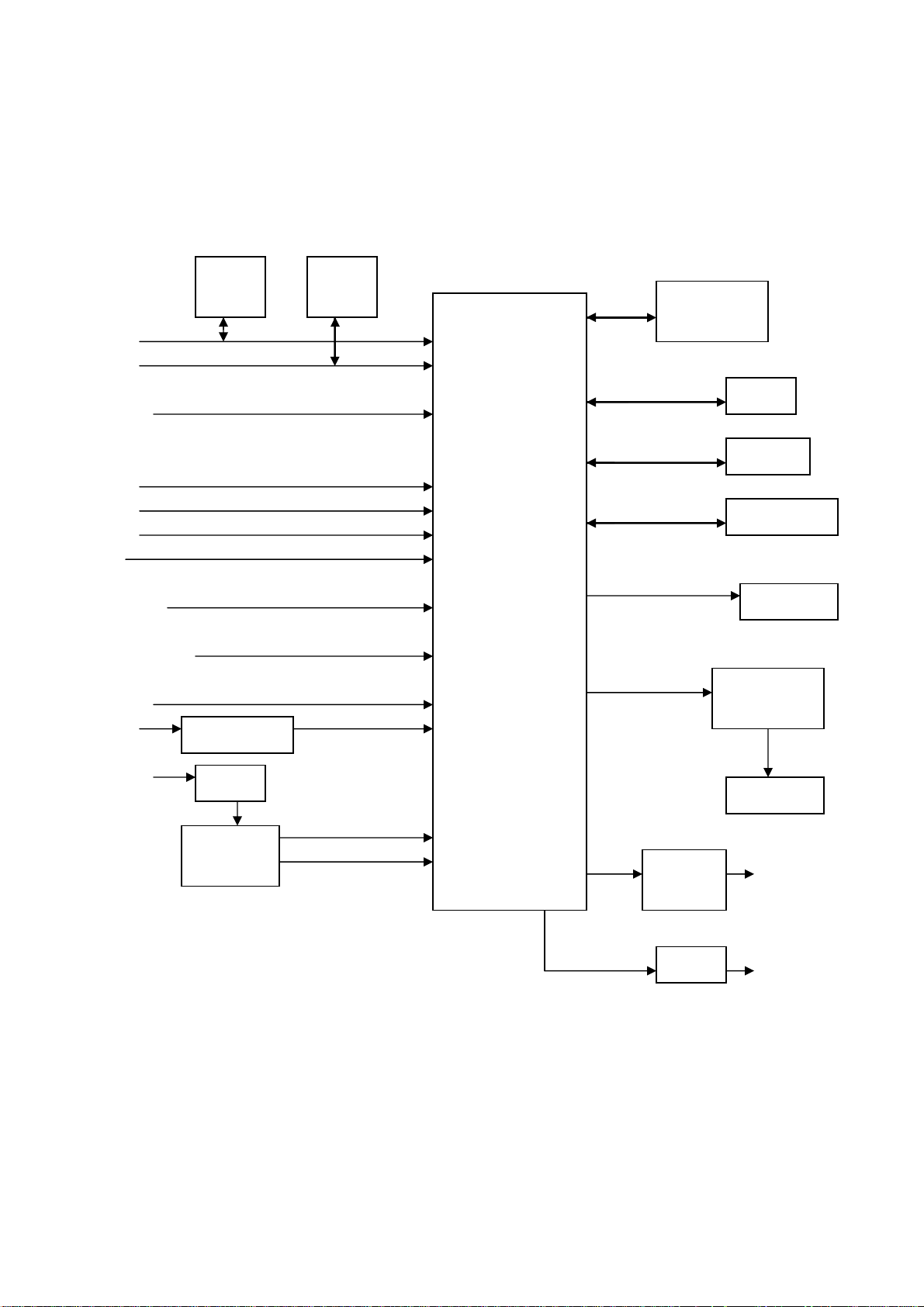
Block diagram
HDMI
VGA
YPbPr
AV1-V
AV2-V
S-Y
S-C
VGA-L/R
AV1/YPbPr-L/R
AV2-L /R
RS232
TUNER
TV-V
TV-SIF L/R-AV OUT
CVBS
V-AV OUT
EDID
24C02
MAX232
SAW
IF AMP
R2S10401
EDID
24C02
LCD TV
CONTROLLER
MST9U19A
POWER MEG.
ATMEG8 L
FLASH
EEPROM
HDCP KEY
PANEL
AUDIO AMP .
R2S15102
SPEAKER
AMP
LM358
2*AMP
7
Page 10

IC block diagram
MST9U19A:
4, 5, 7, 8, 10, 11, 1, 2: HDMI input
16, 17: H/V synchronizing input
27, 25, 22: RGB input
30, 32, 35: YPbPr input
42, 43: S-VIDEO input
46: AV1-V input
47: AV2-V input
49: TV-VIDEO input
51: CVBS output
63, 64: VGA-L/R input
66, 67: AV1/ YPbPr-L/R input
68, 69: AV2/S-L/R input
135: search station synchronizing check input
154: HDMI hot-plug check output
145: standby control output
148: picture on/off output
149: mute control output
72, 73: L/R output (AV-OUT)
74, 75: L/R output (amplifier)
162-271: 4 pairs differential signal and 1 pair
clock signal output
131: SDA
132: SCL
8
Page 11

R2S10401:
9
Page 12

1, 2: VIF input
23: SIF input
7: TV-CVBS output
10: TV-SIF output
17: SDA
18: SCL
R2S15102NP:
5, 11: L/R input
1, 15: L/R output
13: mute control input
10
Page 13

11
Page 14

12
Page 15

Wiring diagram
patch plug
patch plug
signal board
power board
patch plug
patch plug
patch plug
patch plug
patch plug
patch plug
patch plug
main board
brown
blue
power switch
brown
blue
weld
weld
weld
fix the screws on the metal frame of the panel
ground (yellow and green wire)
weld
patch plug
three-pin power plug
IR board
patch plug
key board
speaker socket
13
Page 16

Trouble shooting
1. No raster
Turn on power supply, check
if the red indicator is light in
the STANDBY?
Check if PIN9 (5V) of XS12
on the main board is normal?
Check STANDBY circuit of
power supply board
no
no
no
Replace NS2
yes
Press POWER button in the
unit or sensor control and
check the indicator.
blue
Check if the PIN3 of XS14 on
the main board is high-level?
yes
no
Check the power
board
Replace
NS14
red
Check if XS12 pin 1,2,3 on
main board is high-level?
yes
Check power
supply board
14
Page 17

2. Raster, but no picture
Check if the unit button
and remote control
operation?
yes
no
no
Replace
main board
no
Enter factory-menu,
initialization EEPROM,
then turn off the TV,
turn on again, display
picture?
Does display OSD
menu in screen when
press menu button?
yes
Adjust main board
again
Replace TUNER
yes
yes
yes
Check if the all
channels have signal?
Which is no signal
of channels?
Check if 2VPP signal
and noise wave of
N101(PIN7) on the
main board?
no
Check IF circuit
(N101)
no
TV
no
Check if output
IF signal of
TUNER (pin11)
is normal?
yes
HDMI/VGA/YPRPB
Replace
main board
15
Page 18

3.no sound
Check if PIN2, 3,13 and
14 voltage of NV4 is
normal?
Check power supply
no
yes
Check PIN5 and
PIN11 output wave of
NV4
no
Check PIN10 wave of
N101
no
Check PIN11 wave of
TUNER
no
Replace TUNER
yes
yes
yes
Replace NV4
Replace NS2
Replace N101
16
Page 19

main board
Page 20

main board
Page 21

main board
Page 22

main board
4
Page 23

main board
Page 24

IR board
key board
Page 25

APPENDIX-A: Main assembly 9432HU3512
NAME NO.
Main board
IR board
Key board
Remote control
Panel
6HU06801E0
6HU0660910
6HU0660510
6010Y05701
5205321201
MAIN COMPONENT AND IT'S NO.
N101
NV4
NS2
RC-Y57-0A
PDP32F1
R2S10401 (5271040101)
R2S15102 (5271510201)
MST9U19A (5270019001)
APPENDIX-A: Main assembly 9432HU3514
NAME NO.
Main board
IR board
Key board
6HU0660110
6HU0660910
6HU0660510
MAIN COMPONENT AND IT'S NO.
N101
NV4
NS2
R2S10401 (5271040101)
R2S15102 (5271510201)
MST9U19A (5270019001)
Remote control
Panel
6010Y05701
5205321202
RC-Y57-0A
PDP32F1X031
Page 26

APPENDIX-B: Exploded view (PS-32X35)
Page 27

PART LIST OF EXPLODED VIEW
NO. EDSCRIPTION
1 front cabinet
2 fiter glass
3 panel
4 push board
5 main frame
6 push board
7 main board
8 socket
9 wall mounting bracket
10 back cabinet
11 speaker connection
12 right speaker
13 stand
14 speaker back cover
15 back baffle
16 left speaker
17 connection bracket
18 push board
19 power socket
20 push board
21 decorative bar
22 key board
23 IR board
24 power switch
Note: design and specifications are subject to change without notice.
Page 28

9432HU3512
Ver.1.0
 Loading...