

Page 1
PDP TELEVISION
PH-50HU31
Page 2

CONTENTS
Safety precautions………………………………………………………………………..…
Alignment instructions …………………………….…….…………………………………
Method of software upgrading……………………………………………………………..
Working principle analysis of the unit……………………………….………….………….
Block diagram…………………………………..………………………………….…………
IC block diagram………………………………………………………………………..……
Wiring diagram …………………………………………………………………………….
Troubleshooting guide ………………………………………………………………..……
Schematic diagram…………………………………………………………………………
APPENDIX-A: Assembly list
APPENDIX-B: Exploded View
1
3
6
12
13
14
20
21
26
Page 3

Attention: This service manual is only for service personnel to take reference with. Before
servicing please read the following points carefully.
Safety precautions
Please read the “Points for attention for the Maintenance & Repair of PDP” and “Criterion for
Identifying the Defects on Screen” as below, before inspecting and adjusting the TV set.
1. “Points for attention for the Maintenance & Repair of PDP”
To avoid possible danger, damage or jeopardy to health and to prevent PDP screen from new
damage, the maintenance people must read the following carefully. If they ignore the following
warnings, there will be deathful risks:
1.1 Screens vary from one model to another and therefore not interchangeable. Be sure to use the
same type of screen in the replacement.
1.2 The operation voltage is approximately 350v for PDP module (including screen, driving circuit,
logic circuit and power module). If you want to conduct maintenance work on PDP module when the
set is in normal operation or just after the power is off, you must take proper measures to avoid
electric shock and never have direct contact or touch with the circuitry of the working module or
metal parts. That’s because within a short time relatively high voltage still remains on the capacitor
of the driving part even after the power is off. Make sure to begin relevant maintenance operation at
least one minute after the power is off.
1.3 Don’t apply on the module any power supply that is higher than the specification. If the power
supply used deviates from the value given in the specification, there might be a possibility of leading
to fire or damage to the module.
1.4 Never have operation or mounting work under unsuitable environment such as areas in the
vicinity of water (bath room, laundry, water chute of kitchen), sources of fire, heat-radiation parts or
direct exposure to sunlight. Otherwise there will be kickbacks.
1.5 In case foreign substances such as water, liquid, metal slices or others fall into the module
carelessly power must be cut off immediately. Keep the module as it is and do not move anything on
the module. Otherwise it might be possible to contact the high voltage or cause shock short circuit
so that it may lead to fire or electric shock.
1.6 If there is smoke, abnormal smell or sound from the module, please cut the power off
immediately. Likewise in case the screen doesn’t work when the power is on or during the operation,
please also cut off the power at once. No more operation in this case.
1.7 Do not remove or plug its connection wire when the module is in operation or right after the
power is off. That’s because there remains a relatively high voltage on the capacitor of the driving
circuit. If there is a need to remove or plug in the connection wire, please wait at least one minute
after the power is off.
1.8 Considering the module has a glass faceplate, please avoid extrusion by external force lest it
should cause glass breakage that may get people injured. Two people are needed in cooperation to
move this module lest contingency takes place.
1.9 The complete TV set is designed on the basis of full consideration of thermal dissipation by
convection, with the round hole on the top for heat emission. To avoid overheat, please do not have
any covering on the hole during normal operation and never put it in the place where the space is
1
Page 4
narrow and in bad ventilation.
1.10 There are quite a number of circuits in PDP that are integrated ones. Please be on guard
against static electricity. During maintenance operation be sure to cover yourself with anti-static bag
and before operation make sure to have it sufficiently grounded.
1.11 There are a big number of connection wires distributed around the screen. Please take care
not to touch or scuff them during maintenance or removing the screen, because once they are
damaged the screen will fail to work and it’s not possible to repair it.
If the connection wires, connectors or components fixed by the thermotropic glue need to disengage
when service, please soak the thermotropic glue into the alcohol and then pull them out in case of
damage.
1.12 Connector for the circuit board of the screen part is relatively fine and delicate. Please take
care in the replacement operation lest it should get damaged.
1.13 Special care must be taken during transportation and handling because strenuous vibration
could lead to screen glass breakage or damage on the driving circuitry. Be sure to use a strong
outer case to pack it up before transportation or handling.
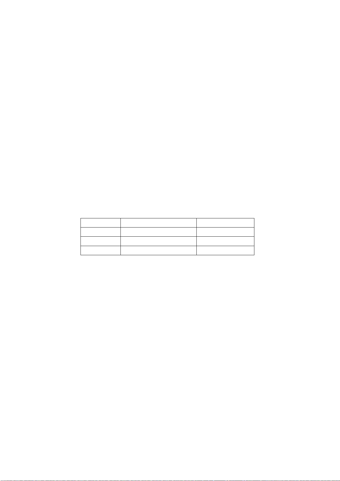
1.14 Please put it for storage in an environment in which the conditions are under control so as to
prevent the temperature and humidity from exceeding the scope stipulated in the specification. For
prolonged storage please cover it with anti-moisture bag and have them piled and stored in one
place. The environmental conditions are tabulated as below:
Temperature Scope for operation 0~50centigrade
Scope for storage -15~60centigrade
Humidity Scope for operation 20%~80%
Scope for storage 20%~80%
1.15 If a fixed picture is displayed for a long time, difference in its brightness and color may occur
compared with movable pictures. But it doesn’t show any problem and the reason is that there is
reduced density of fluorescent powder in the former. On the other hand, even if changes take place
in the picture, it can keep its brightness for a period of time (several minutes). It’s a feature inherent
with plasma and it’s not abnormal. However please try as much as possible to avoid showing a still
picture of high brightness for a long time during operation.
1.16 As a digitalized display devise, this module is provided with error diffusion technology and the
gray scale and false enhancement of contour can be displayed by reusing of sub-field. As compared
with cathode ray tube, it can be found in the moving picture that at the brim of the face of a person
there are some wrong colors.
1.17 During the display of graph (indicating the gradual change in brightness horizontally or
vertically) resulting from gray scale test it can be found that the brightness for the two adjacent
levels is uneven. This is caused by the reuse of sub-field, the display of load rectification and the
electrolysis.
1.18 The screen front plate is of glass. Please make sure that the screen has been put in place
during erection. If it is not in place before the erection begins it may lead to screen crack or
breakage.
1.19 Make sure the screw used in the mounting of the screen is of the original specs lest it should
cause damage to the screen due to mismatch. Special care should be taken not to use too long or
2
Page 5
too big screw.
1.20 Care must be taken to guard against dust during assembling or dismantling, especially to avoid
dirt from falling in between the screen and the glass lest it should harm the receiving and viewing
effect.
1.21 There is piece of insulator stuck on the rear chassis corresponding to the power supply board.
It is used to isolate the cool part from the hot part. Please take care to keep it intact lest it should
become a potential safety trouble.
1.22 In addition to plasma screen, the glass is a part of high value. It has such functions as
anti-radiation, adjustment of color temperature etc. Please handle it carefully.
Alignment instructions
1. Test equipment
PM5518 (video signal generator)
VG-849 (VGA and HDMI signal generator)
CA210 (white balancer)
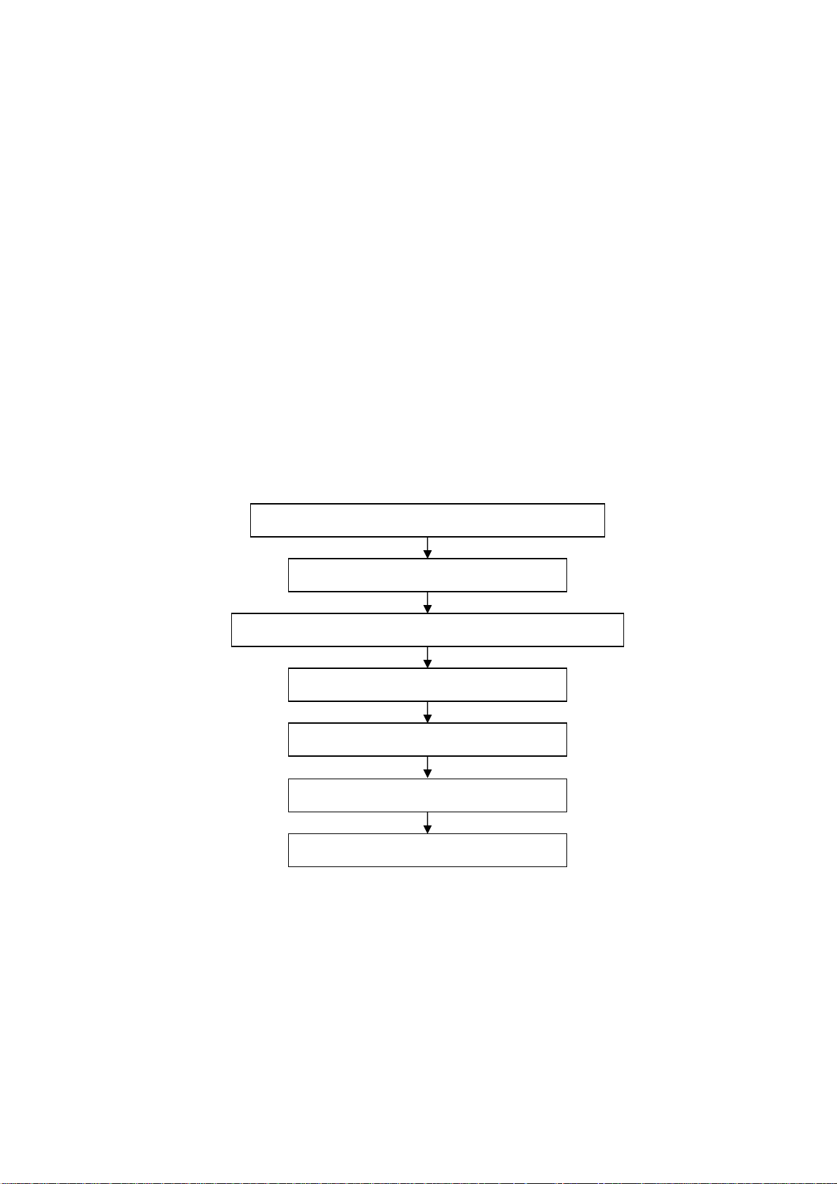
2 Alignment flow-chart
The alignment flow-chart is shown as fig-1
Check DDC, HDCP KEY, FLASH and POWER control IC
Factory initialization setup
IF channel AFT voltage of TV and AGC voltage
VGA, YPbPr ADC correction
White balance adjustment
Fig-1 adjustment flow-chart
3 Unit adjustments
Connect all the boards according to wiring diagram, connect with power and observe the display.
Method for entering factory menu: press “INPUT”, “2”, “5”, ”8” and “0” in turn to enter factory
menu; press “CH+” and “CH-” to select adjustment items and press “VOL+” and “VOL-” to adjust
value items, press “MENU” repeatedly to exit.
Method for software upgrading: enter factory menu and select “OPTION”, set ISP to 1 or insert
jump wire J1, then you can upgrade on line. After upgrade, set ISP back to 0 or pull out jump wire
J1.
Performance check
Preset ex-factory
3
Page 6
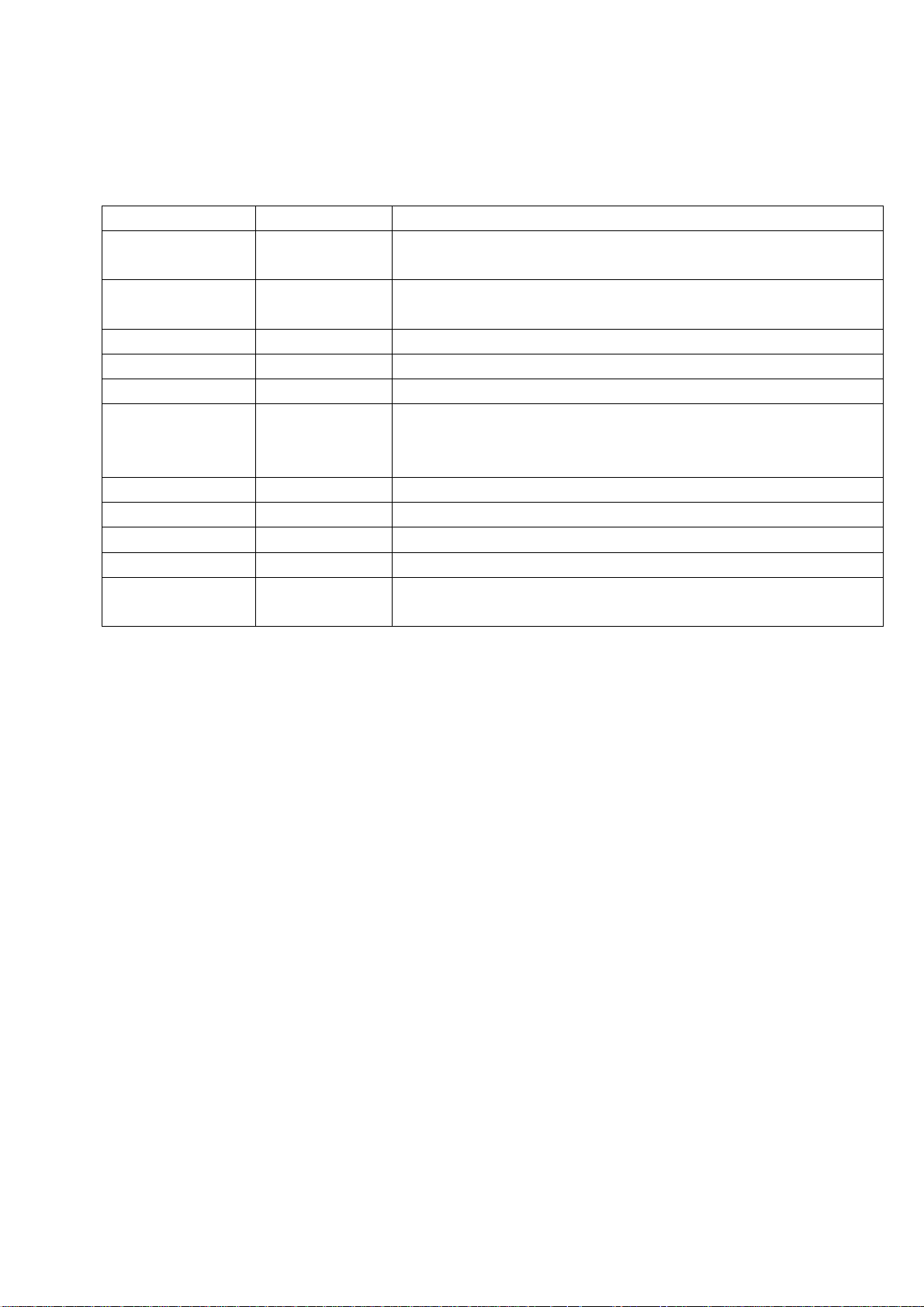
3.1 Initialization
Enter factory menu, select “OPTION” and “HOTEL OPTION” sub-menu, adjustment of items to see
table1.
Table1 sub-menu adjustment
Items Preset Introduce
HOTEL 0 1: HOTEL OPTION of factory menu is optional
0: HOTEL OPTION of factory menu is not optional
LOGO 1 1: display LOGO in no signal or turn on
0: no LOGO display
ADC PRESCALE 00A Software auto preset according the power consumption
SIF PRESCALE 000 Software auto preset according the power consumption
BACK LIGHT 13 Software auto preset according the screen
ALL COLOR 1 1: white balance of each channel auto offset based on the HDMI white
balance
0: white balance of each channel adjust the offset base separately
NO STANDY 0 0 01: turn on 00: memory function of turn on 10: standby
INIT VOLUME 0-100 Volume when turn on
INIT CHANNEL 1-200 Channel when turn on
INIT SRC Program source Input Source when turn on
EEPROM-MEMORAY
RECALL
> EEPROM Initialization (operate when EEPROM data chaos)
3.2 Adjustment for AFT voltage and AGC voltage of IF channel in TV
3.2.1 IF AFT adjustment
Enter factory menu, set IF VCO to 1, or press ”INPUT”, “2”, “5”, “8”, “1” to enter VCO
adjustment mode, disconnect J2, adjust LZ100 to value 2.5V of TP5(B face), then wed J2.
3.2.2 IF AGC adjustment
Input 184.25MHz RF signal of 60DBuv from RF terminal for china, and 175.25MHz for
America, adjust RZ133 to value 2V of TP1(B face) and there should be no obvious snowy picture.
Increase the signal to 90DBVuv and it should be display normally and no obvious noise.
3.3 White balance adjustment
3.3.1 HDMI white balance correct
a. Input VG-848 signal to HDMI: TIMING854(800*600/60Hz) 8 level gray scale of PAT920,
adjust the balance with CA210.
b. Enter COLOR TEMP sub menu and select color temperature of standard(9300K)
c. Fixed B OFF, adjust R OFF, G OFF to let the color coordinate of the second level be
283,297(CPT panel) and the brightness be 3nit ~10nit or so; Fixed B GAIN, adjust R GAIN, G GAIN
to let the color coordinate of the seventh level be 283,297(CPT panel). Repeat adjust R OFF, G OFF,
R GAIN and G GAIN, until the two color coordinate of the level gray scale be 283,297(CPT panel).
3.3.2 VGA/YPbPr white balance check and correct
a. Connect VG-848 signal of VGA to VGA terminal and input TIMING854(800*600/60HZ)
(PATTERN:CROSS), and auto adjust to full screen then input PAT948 black/white signal, enter
submenu of ADC ADJ, select AUTOTUNE and wait for OK display. Input PAT920(8 gray levels),
check if the white balance is normal, if not, set ALL COLOR to 0 and fine adjust according the
4
Page 7
method of 3.3.2
b. connect VG-848 signal of YPbPr to YPbPr terminal and input TIMING972(1080I/60Hz)
PAT908 color bar(include back/white bar), enter submenu of ADC ADJ, select AUTOTUNE and wait
for OK display. Input PAT920(8 gray levels), check if the white balance is normal, if not, set ALL
COLOR to 0 and fine adjust according the method of 3.3.2
c. Input AV signal(PM5518, 8 gray levels PAL for China and NTSC for America) to VIDEO 1
terminal, check if the white balance is normal, if not, set ALL COLOR to 0 and fine adjust according
the method of 3.3.2.
Note: it can’t set back to 1 once ALL COLOR changes to 0.
4 Performance check
4.1 TV function
Enter searching menu → auto search, connect RF-TV terminal with central signal source and check
if the picture is normal, if there are channels be skipped. Check CCD and V-CHIP function for
America.
4.2 AV/S, YPbPr terminals
Input AV/S, YPbPr/YCbCr HD signal, check if it is normal.
4.3 VGA terminal
Insert VGA terminal, input VGA format signal of 640X480@60 Hz and check if the display is normal.
4.4 HDMI terminal
Insert HDMI terminal, input 640X480@60Hz signal, check if the display is normal. Check HDCP
function.
4.5 check sound channel
Check the speaker and earphone of each channel.
4.6 RS232 terminal
Put the earphone line into COM terminal, check the long-distance control function with special test
software.
4.7 other function check
Check the turn on/turn off timer, asleep timer, picture/sound mode, OSD, freeze/mute,
stereo/SAP(for America), ect.
4.6 presetting before ex-factory
Item Setting Item Setting Item Setting
PICTURE MODE NAUTRAL OSD English/Chinese
COLOR MODE DK HALFTONE 50
SOUND MODE NEWS DURATION 15 VGA/HDMI STANDARD
NR WEAK ANTENNA CATV
ZOOM FULL Turn off channel TV
5
Page 8
Method of software upgrading
1. The tools and software demanded
1) Please confirm that PC has the software of ISP_TOOL and install the parallel interface drive
program Port95nt.
2) ISP_TOOL icon is bellow:
3) One serial cable (25 pins) and one VGA cable (15 pins), the serial cable connects the PC and the
upgrade instrument, the VGA cable connects the TV and the upgrade instrument.
2. The steps for upgrading software
1) Please confirm that the connection wires and the upgrade instrument are connected well before
the software written and then power on the TV.
2) Double click the icon ISP_TOOL to open it:
3) Press “Connect“ to connect TV, if the connection is done successfully as shown below, then
press “enter”.
6
Page 9
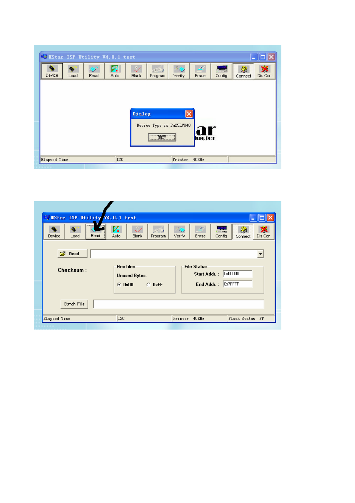
Note: if it appears error, check the connection wires and check if ISP item of the factory menu is set
to 1, if not, please set it to 1.
4) After connection is done, it needs to read the Binary document. Press “Read” as shown below:
5) Search the document needed to write in the “Read” check box.
7
Page 10
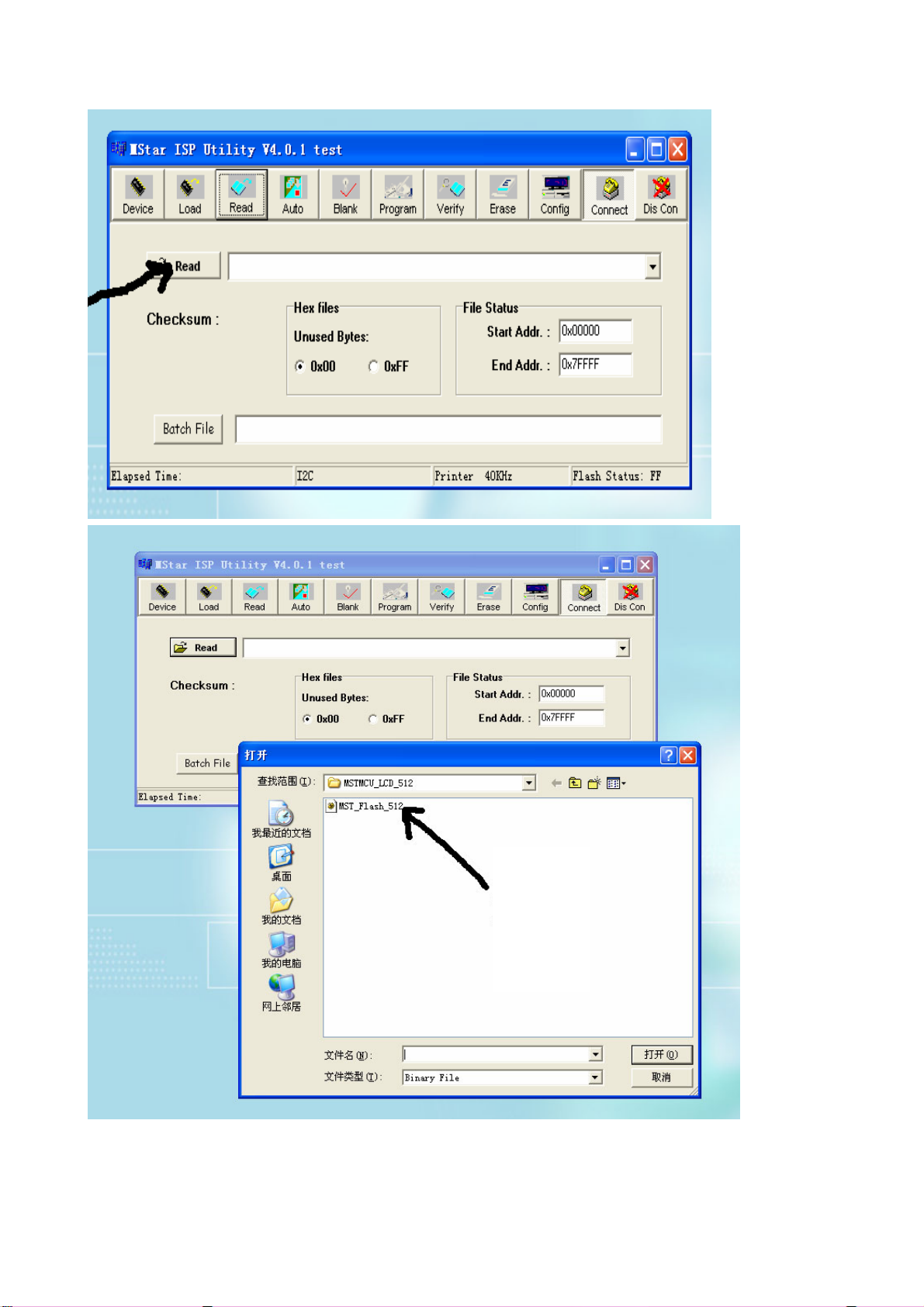
Select
6) Select the document then the window will appear as shown below:
8
Page 11

7) Press “Auto” to select the writing function.
Select the items shown in the picture above:
(a) Read File
9
Page 12
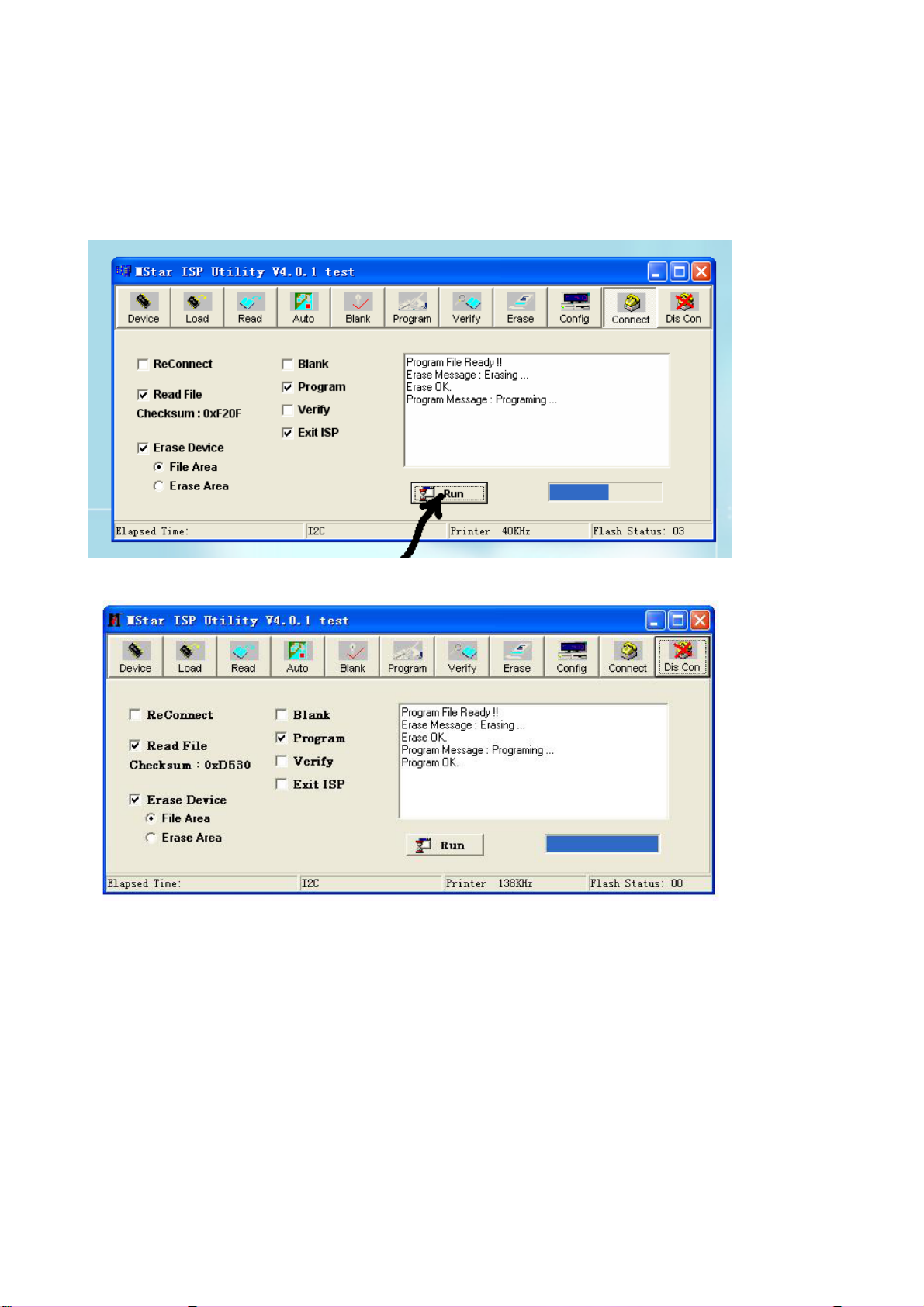
(b) Program
(c) Exit ISP
(d) Erase Device
(e) File Area
8) Press “Run” to begin the writing program, wait till the blue bar is complete.
After writing, it will display OK:
If there is error appeared (shown as below), press “Run” again to rewrite the program till it is
success.
10
Page 13
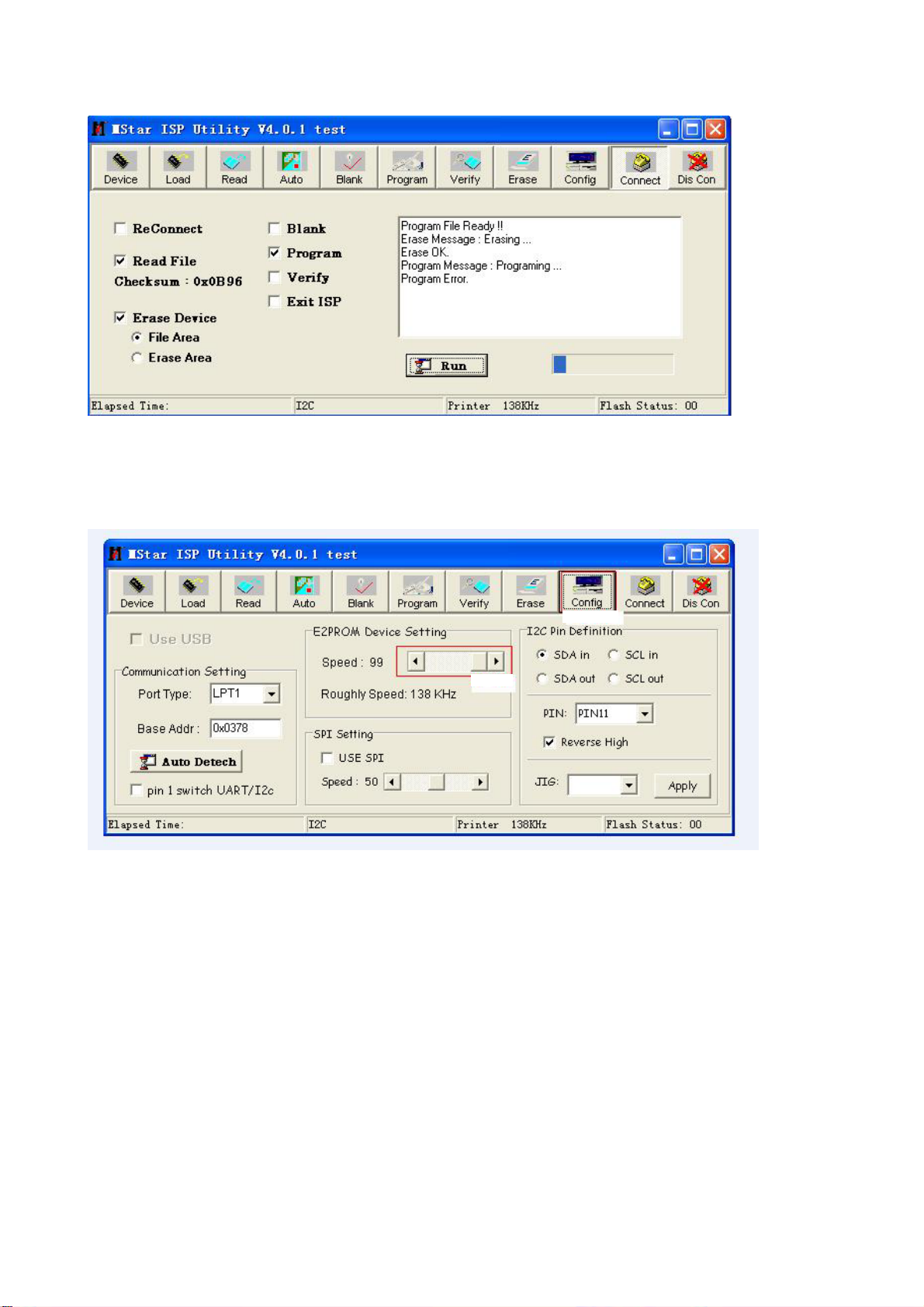
Note1: keep the connection well and don’t cut off the power during the writing process.
Note2: the writing speed can be adjusted as shown below. Select “Config” then adjust Speed BAR,
the value is bigger the speed is faster. But it is easier to appear error when increase the speed, so it
need to select a suitable speed according the PC.
Step 1
Step 2
11
Page 14

Working principle analysis of the unit
The RF signal received by antenna will be sent to tuner TUN1, then IF signal will be obtained
through high amplifier and mixed frequency, through pre-intermediate amplified by VZ100, then it
will be sent to acoustic surface-wave ZZ101 to do IF filter and get better IF characteristics, then it
will be sent to NZ100 (R2S1040) to do intermediate amplification, phase-locked loop VCO and
synchronous wave detection to get video signal TV-CVBS; after pre-intermediate amplification IF
will also be sent to acoustic surface-wave ZZ100 to do filter at the same time, then it will be sent to
NZ100 to do intermediate amplification and output the second sound intermediate frequency signal
(TV-SIF).
The TV-CVBS signal output from R2S1040 together with TV-SIF will be sent to main IC NS4
(MST9U88L). Video signal of AV1, AV2, S-VIDEO, YPbPr1 and YPbPr2 will also be sent to
MST9U88L; while the audio signal of them via audio switch NW200(HEF4052BT) selection to
MST9U88L (AV1 and S-VIDEO share one audio port). Video and audio signal of VGA, HDMI will be
sent to MST9U88L, too.
The main IC NS4(MST9U88L) is a high performance and fully integrated IC, which can realize
HDMI interface processing, video demodulating, video switch selection, A/D and D/A conversion,
interlace/de-interlace processing, modes conversion, OSD and low-voltage differential output, ect.
And it also has functions of audio selection, processing and MCU.
The video signal via MST9U88L processing, output 4 pairs differential signal and 1 pair clock
signal for PDP panel display. Video signal of AV1, AV2, S-VIDEO and TV via initial selection and
processing, output video signal of AV-OUT, after double video amplifying, it will be sent to AV-OUT.
Audio signal via MST9U88L processing, output two ways; one way will be sent to sound
amplifier NA6 (MP7722DF) amplifying, then sent to speaker. At the same time, it also sent to
earphone sound amplifier N350 (BH3547F), after amplifying then sent to earphone. Another way
will be sent to D/A converter NS6 (CS4344) through I2S bus, convert to analog sound signal L/R
output through AV-OUT.
12
Page 15

Block diagram
HDMI
VGA
YPbPr1
YPbPr2
AV1-V
AV2-V
S-Y
S-C
VGA-L/R
YPbPr1-L/R
YPbPr2-L/R
AV1-L /R
AV2-L /R
TUNER
TV-V
TV-SIF
V- AV OUT
L/R-AV OUT
CVBS
EDID
24C02
AUDIO SW.
HEF4052
EDID
24C02
SAW
IF AMP
R2S10401
IIS
2*AMP
POWER MEG.
ATMEG8 L
LCD TV
CONTROLLER
MST9X88LD
HP AMP
BH3547F
D/A
CS4334
DDR
FLASH
EEPROM
HDCP KEY
PANEL
AUDIO AMP .
MP7722
SPEAKER
HEAD
PHONE
13
Page 16

IC block diagram
1. MST9U88L
The MST9U88L is a high performance and fully integrated IC for multi-function LDC monitor/TV with
resolutions up to SXGA/WXGA. It is configured with an integrated triple-ADC/PLL, an integrated
DVI/HDCP/HDMI receiver, a multi-standard TV video and audio decoder, a video de-interlacer, a
scaling engine, the MStarACE-3 color engine, an on-screen display controller, an 8-bit MCU, and a
built-in output panel interface. With external frame buffer, 3-D video decoding and processing are
fulfilled for high-quality TV application. To further reduce system costs, the MST9U88L also
integrates intelligent power management control capability for green-mode requirements and
spread-spectrum support for EMI management.
14
Page 17

Pins description:
4, 5, 7, 8, 10, 11, 1, 2: HDMI input
16, 17: horizontal/vertical synchronous input
27, 25, 22: RGB input
30, 32, 35: YpbPr2 input
41, 44, 46: YpbPr1 input
48, 49: S-VIDEO input
54: AV1-V input
55: AV2-V input
57: TV-CVBS input
59: CVBS output(AVOUT-V)
71, 72: VGA-L/R input
73, 74: AV1(S)/AV2/ YpbPr1/ YpbPr2-L/R input
178: search program synchronous test input
188: HDMI hot-plug test output
189: image switch output
192: backlight control output
193: panel voltage contort output
85, 86: L/R output
234,236,238,239: I2S bus(AVOUT-A)
199-208: 4 pairs differential signal and 1pair clock signal output
174: SDA
175: SCL
2. R2S10401
R2S10401SP is a semiconductor integrated circuit consisting of PLL split-carrier VIF/SIF signal
processing system compliant with PAL.
15
Page 18

16 17
Page 19

Pin description:
1, 2: VIF input 10: TV-SIF output
23: SIF input 17: SDA
7: TV-CVBS output 18: SCL
3. MP7722DF
The MP7722 is a stereo 20W Class D Audio Amplifier. It is one of MPS’second generation of fully
integrated audio amplifiers which dramatically reduces solution size by integrating the following:
180mΩ power MOSFETs
Startup / Shutdown pop elimination
Short circuit protection
Mute / Standby
The MP7722 utilizes a single ended output structure capable of delivering 2 x 20W into 4Ωspeakers.
MPS Class D Audio Amplifiers exhibit the high fidelity of a Class A/B amplifier at efficiencies greater
than 90%. The circuit is based on the MPS’ proprietary variable frequency topology that delivers low
distortion, fast response time and operates on a single power supply.
Page 20

18 19
Page 21

Pin description:
1, 7: L/R input
19, 14: L/R output
6, 10: mute control input
Page 22

Page 23

Trouble shooting
1. Fault clearance
Before servicing please check to find the possible causes of the troubles according to the table
below.
1.1 Antenna (signal):
Picture is out of focus or jumping z Bad status in signal receiving
z Poor signal
z Check if there are failures with the electrical connector or
the antenna.
z Check if the antenna is properly connected.
Fringe in picture z Check if the antenna is correctly oriented.
z Maybe there is electric wave reflected from hilltop or
building.
Picture is interfered by stripe shaped
bright spots
There appear streaks or light color
on the screen
1.2 TV set:
Symptoms Possible cause
Unable to switch the power on z Check to see if the power plug has been inserted properly
No picture and sound z Check to see if the power supply of liquid crystal TV has
Deterioration of color phase or color
tone
Screen position or size is not proper z Check is the screen position and size is correctly set up.
Picture is twisted and deformed z Check to see if the picture-frame ratio is properly set up.
Picture color changed or colorless z Check the “Component” or “RGB” settings of the liquid
z Possibly due to interference from automobile, train, high
voltage transmission line, neon lamp etc.
z Maybe there is interference between antenna and power
supply line. Please try to separate them in a longer
distance.
z Maybe the shielded-layer of signal wire is not connected
properly to the connector.
z Check if interfered by other equipment and if interfered
possibly by the equipment like transmitting antenna,
non-professional radio station and cellular phone.
into the socket.
been switched on. (As can be indicated by the red LED at
the front of the TV set)
z See if it’s receiving the signal that is transmitted from other
source than the station
z Check if it’s connected to the wrong terminal or if the input
mode is correct.
z Check if the signal cable connection between video
frequency source and the liquid crystal TV set is correct.
z Check if all the picture setups have been corrected.
crystal TV set and make proper adjustment according to the
21
Page 24

signal types.
Picture too bright and there is
distortion in the brightest area
Picture is whitish or too bright in the
darkest area of the picture
No picture or signal produced from
the displayer if “XXX in search”
appears.
There appears an indication -
“outside the receivable scope)
Remote control cannot work
properly
No picture and sound, but only
hash.
Blur picture z Check if the antenna cable is correctly connected.
No sound z Check if the “mute” audio frequency setting is selected.
When playing VHS picture search
tape, there are lines at the top or
bottom of the picture.
z Check if the contrast setting is too high.
z Possibly the output quality of DVD broadcaster is set too
high.
z It maybe also due to improper terminal connection of the
video frequency signal in a certain position of the system.
z Check if the setting for the brightness is too high
z Possibly the brightness grade of DVD player (broadcaster)
is set too high.
z Check if the cable is disconnected.
z Check if it’s connected to the proper terminal or if the input
mode is correct.
z Check if the TV set can receive input signal. The signal is
not correctly identified and VGA format is beyond the
specified scope.
z Check if the batteries are installed in the reverse order.
z Check if the battery is effective.
z Check the distance or angle from the monitor.
z Check if there is any obstruct between the remote control
and the TV set.
z Check if the remote control signal- receiving window is
exposed to strong fluorescence.
z Check if the antenna cable is correctly connected, or if it
has received the video signal correctly.
z Of if it has received the right video signal.
z Check if the sound volume is set to minimum.
z Make sure the earphone is not connected.
z Check if the cable connection is loose.
z When being played or in pause VHS picture search tape
sometimes can’t provide stable picture, which may lead to
incorrect display of the liquid crystal TV, In this case please
press “auto” key on the remote control so as to enable the
liquid crystal TV set to recheck the signal and then to
display correct picture signal
22
Page 25

2. Troubleshooting guide
2.1. No raster
Turn on power supply, check
if the red indicator is light in
the STANDBY?
no
Check if X303 PIN3 (5V) of
main board is normal?
no
Check STANDBY circuit of
power supply board
Replace 01 board
no
Check the
power board
yes
Press POWER button on the
unit or remote sensor control
and check the indicator.
Check if the PIN27 of X304
on 01 board is high-level?
no
Check if Va, Vs of X5201,
X5209 on the power board
is normal?
yes
Check the panel
yes
blue
no
Replace
N102
red
Check if the PIN11 of X303 in
main board is high-level?
yes
Check power
supply board
23
Page 26

2.2. Raster, but no picture
Check if the unit button
and remote control
operation?
yes
no
no
Replace
main board
no
Enter factory-menu,
initialization EEPROM,
then turn off the TV,
turn on again, display
picture?
Adjust main board
Does display OSD
menu in screen when
press menu button?
yes
yes
again
yes
Replace TUNER1
yes
Check if the all channels
have no signal?
no
Which is no signal
of channels?
TV
Check if 1VPP signal
and noise wave of
XB201 11# on the TV
board?
no
Check if output IF
no
signal of TUNER1
(pin 11) is normal?
yes
Check IF (NZ100)
and its periphery
HDMI/VGA/YPRPB
Replace
main board
24
Page 27

2.3.no sound (TV input)
Check if PIN2, 8, 13 and
18 voltage of NA6 is
normal?
no
Check power board
yes
Check PIN3 and
PIN7 output wave of
NA6
no
Check PIN10 wave of
NZ100
no
Check PIN11 wave of
TUNER1
no
Replace TUNER1
yes
yes
yes
Replace NA6
Replace NS4
Replace NZ100
25
Page 28

main board
Page 29

main board
Page 30

main board
Page 31

main board
Page 32

analog board
Page 33

key board
Page 34

IR board
Page 35

AV board
Page 36

Power board-A
Page 37

Power board-B
Page 38

APPENDIX-A: Main assembly 9350HU3123
NAME NO.
Analog board
Main board
Interface connection board
Key board
IR board
Power filter board
Power board
Remote control
Panel
MAIN COMPONENT AND IT'S NO.
6HU0595310
6HU05901B0 NS4 MST9U88L (5270988001)
6HU0544610
6HU0670510
6HU0670910
6FK0105110
6HV0082010
6010Y04600
5205502101
NZ100
NA6
RC-Y46
S50HW-YD02
R2S10401 (5271040101)
MP7722DF (5277722001)
Page 39

APPENDIX-A: EXPLODED VIEW PH50x31
Page 40

APPENDIX-B: PART LIST OF EXPLODED VIEW
NO. DESCRIPTION
1 front cabinet
2 panel
3 filter glass
4 push board (left)
5 push board (upper1)
6 push board (upper2)
7 push board (right)
8 connection of panel
9 analog board
10 CPU board
11 power switch bracket
12 key board
13 wall mounting bracket
14 back cabinet
15 back baffle
16 speaker back cover (left)
17 speaker back cover (right)
18 stand
19 speaker
20 IR board
21 power cord
22 main frame
23 decorative bar
24 push board (below1)
25 push board (below2)
Note: design and specifications are subject to change without notice.
Page 41

9350HU3123
Ver.1.0
 Loading...