

Page 1
PDP TELEVISION
PH-50HA31
Page 2

CONTENTS
Safety precautions………………………………………………………………………..…
Alignment instructions …………………………….…….…………………………………
Method of software upgrading……………….…….……………………………………….…….
Working principle analysis of the unit……………………………….………….………….
Block diagram…………………………………..………………………………….…………
IC block diagram………………………………………………………………………..……
Wiring diagram …………………………………………………………………………….
Troubleshooting guide ………………………………………………………………..……
Schematic diagram…………………………………………………………………………
APPENDIX-A: Assembly list
APPENDIX-B: Exploded View
1
3
8
10
11
12
19
20
25
Page 3

Attention: This service manual is only for service personnel to take reference with. Before
servicing please read the following points carefully.
Safety precautions
Please read the “Points for attention for the Maintenance & Repair of PDP” and “Criterion for
Identifying the Defects on Screen” as below, before inspecting and adjusting the TV set.
1. “Points for attention for the Maintenance & Repair of PDP”
To avoid possible danger, damage or jeopardy to health and to prevent PDP screen from new
damage, the maintenance people must read the following carefully. If they ignore the following
warnings, there will be deathful risks:
1.1 Screens vary from one model to another and therefore not interchangeable. Be sure to use the
same type of screen in the replacement.
1.2 The operation voltage is approximately 350v for PDP module (including screen, driving circuit,
logic circuit and power module). If you want to conduct maintenance work on PDP module when the
set is in normal operation or just after the power is off, you must take proper measures to avoid
electric shock and never have direct contact or touch with the circuitry of the working module or
metal parts. That’s because within a short time relatively high voltage still remains on the capacitor
of the driving part even after the power is off. Make sure to begin relevant maintenance operation at
least one minute after the power is off.
1.3 Don’t apply on the module any power supply that is higher than the specification. If the power
supply used deviates from the value given in the specification, there might be a possibility of leading
to fire or damage to the module.
1.4 Never have operation or mounting work under unsuitable environment such as areas in the
vicinity of water (bath room, laundry, water chute of kitchen), sources of fire, heat-radiation parts or
direct exposure to sunlight. Otherwise there will be kickbacks.
1.5 In case foreign substances such as water, liquid, metal slices or others fall into the module
carelessly power must be cut off immediately. Keep the module as it is and do not move anything on
the module. Otherwise it might be possible to contact the high voltage or cause shock short circuit
so that it may lead to fire or electric shock.
1.6 If there is smoke, abnormal smell or sound from the module, please cut the power off
immediately. Likewise in case the screen doesn’t work when the power is on or during the operation,
please also cut off the power at once. No more operation in this case.
1.7 Do not remove or plug its connection wire when the module is in operation or right after the
power is off. That’s because there remains a relatively high voltage on the capacitor of the driving
circuit. If there is a need to remove or plug in the connection wire, please wait at least one minute
after the power is off.
1.8 Considering the module has a glass faceplate, please avoid extrusion by external force lest it
should cause glass breakage that may get people injured. Two people are needed in cooperation to
move this module lest contingency takes place.
1.9 The complete TV set is designed on the basis of full consideration of thermal dissipation by
convection, with the round hole on the top for heat emission. To avoid overheat, please do not have
any covering on the hole during normal operation and never put it in the place where the space is
1
Page 4
narrow and in bad ventilation.
1.10 There are quite a number of circuits in PDP that are integrated ones. Please be on guard
against static electricity. During maintenance operation be sure to cover yourself with anti-static bag
and before operation make sure to have it sufficiently grounded.
1.11 There are a big number of connection wires distributed around the screen. Please take care
not to touch or scuff them during maintenance or removing the screen, because once they are
damaged the screen will fail to work and it’s not possible to repair it.
If the connection wires, connectors or components fixed by the thermotropic glue need to disengage
when service, please soak the thermotropic glue into the alcohol and then pull them out in case of
damage.
1.12 Connector for the circuit board of the screen part is relatively fine and delicate. Please take
care in the replacement operation lest it should get damaged.
1.13 Special care must be taken during transportation and handling because strenuous vibration
could lead to screen glass breakage or damage on the driving circuitry. Be sure to use a strong
outer case to pack it up before transportation or handling.
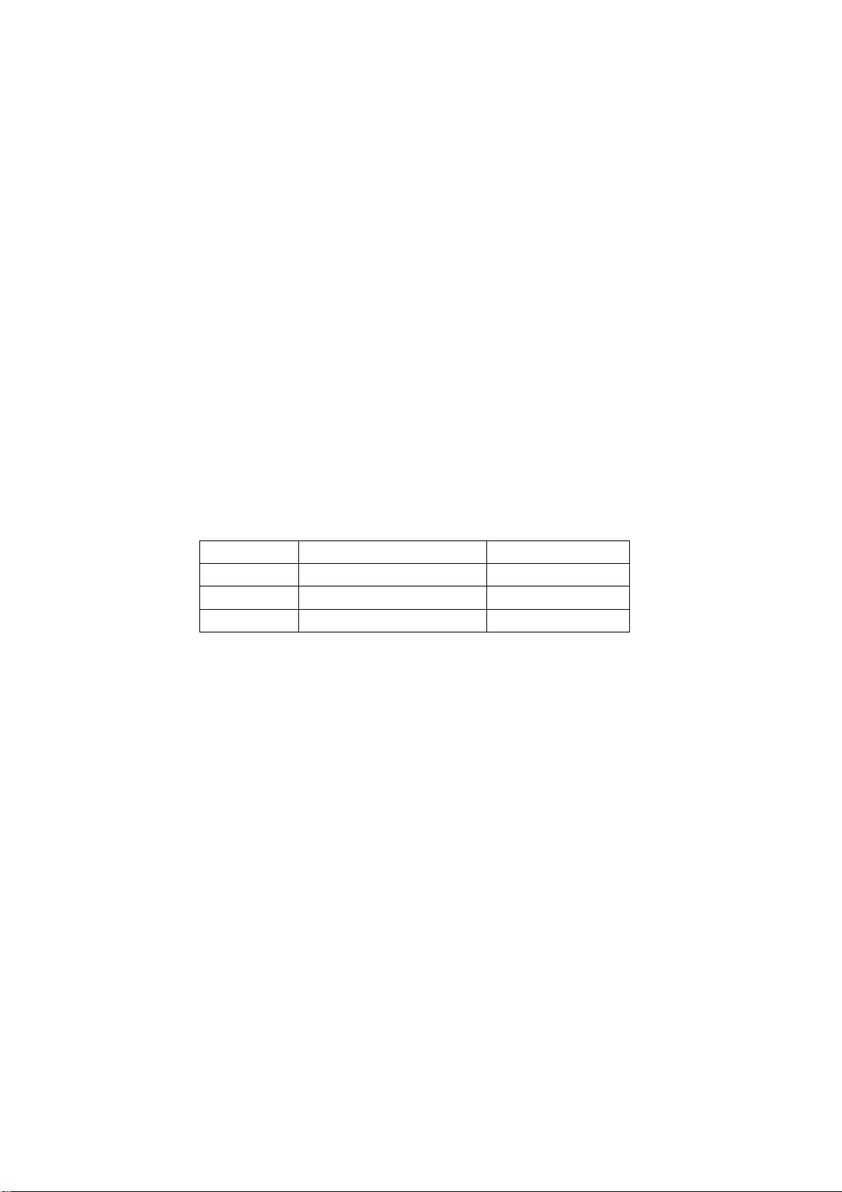
1.14 Please put it for storage in an environment in which the conditions are under control so as to
prevent the temperature and humidity from exceeding the scope stipulated in the specification. For
prolonged storage please cover it with anti-moisture bag and have them piled and stored in one
place. The environmental conditions are tabulated as below:
Temperature Scope for operation 0~50centigrade
Scope for storage -15~60centigrade
Humidity Scope for operation 20%~80%
Scope for storage 20%~80%
1.15 If a fixed picture is displayed for a long time, difference in its brightness and color may occur
compared with movable pictures. But it doesn’t show any problem and the reason is that there is
reduced density of fluorescent powder in the former. On the other hand, even if changes take place
in the picture, it can keep its brightness for a period of time (several minutes). It’s a feature inherent
with plasma and it’s not abnormal. However please try as much as possible to avoid showing a still
picture of high brightness for a long time during operation.
1.16 As a digitalized display devise, this module is provided with error diffusion technology and the
gray scale and false enhancement of contour can be displayed by reusing of sub-field. As compared
with cathode ray tube, it can be found in the moving picture that at the brim of the face of a person
there are some wrong colors.
1.17 During the display of graph (indicating the gradual change in brightness horizontally or
vertically) resulting from gray scale test it can be found that the brightness for the two adjacent
levels is uneven. This is caused by the reuse of sub-field, the display of load rectification and the
electrolysis.
1.18 The screen front plate is of glass. Please make sure that the screen has been put in place
during erection. If it is not in place before the erection begins it may lead to screen crack or
breakage.
1.19 Make sure the screw used in the mounting of the screen is of the original specs lest it should
cause damage to the screen due to mismatch. Special care should be taken not to use too long or
2
Page 5
too big screw.
h
1.20 Care must be taken to guard against dust during assembling or dismantling, especially to avoid
dirt from falling in between the screen and the glass lest it should harm the receiving and viewing
effect.
1.21 There is piece of insulator stuck on the rear chassis corresponding to the power supply board.
It is used to isolate the cool part from the hot part. Please take care to keep it intact lest it should
become a potential safety trouble.
1.22 In addition to plasma screen, the glass is a part of high value. It has such functions as
anti-radiation, adjustment of color temperature etc. Please handle it carefully.
Alignment instructions
1. Test equipment
PM5515 (video signal generator)
MK8258 (YUV, VGA signal generator)
CA210 (white balancer)
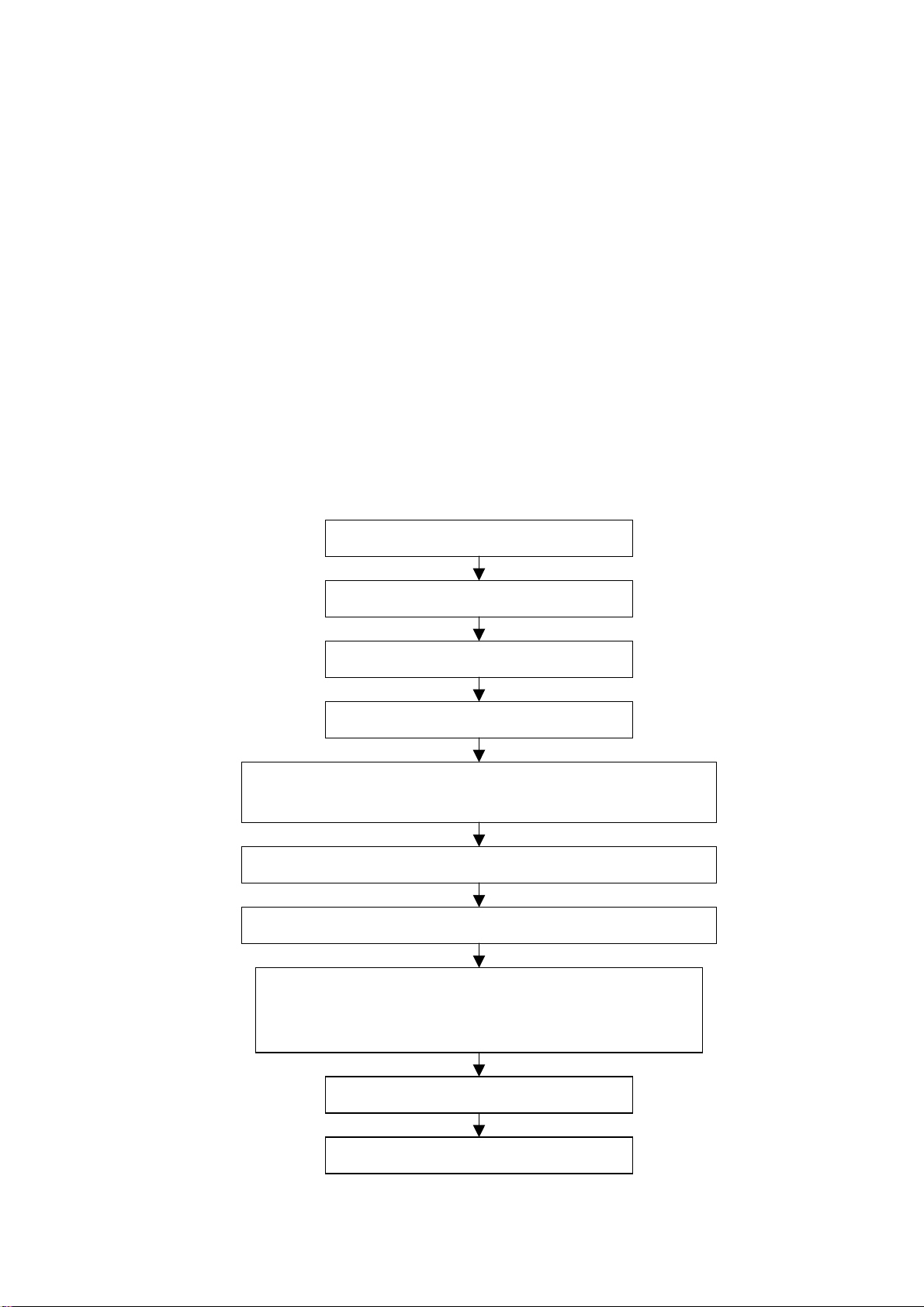
2. The alignment flow chart (see below figure)
Connect with central signal source, then check each function of TV such as
station missing, analog control etc., check the output of headphone and speaker
Input AV/SVIDEO signal, then check each function of all the terminals
Input HD signal (format), then check each function of the terminal
Input VGA, HDMI signal, check if the display is normal, check eac
function such as analog control etc., check horizontal /vertical center etc.
Check the accessories and pack them in box
Check DDC and FLASH
To produce signal board on the line
All testing
Auto correction
Preset ex-factory
3
Page 6

Fig-1 adjustment flow-chart
3. Description of adjustment
3.1 Unit adjustment
Connect the signal processing board, side AV board, button board and remote control receiver
board according to the wiring diagram. Connect with power and observe the display.
Method for using factory menu: press ”INPUT” button, then press”2580” to enter level one factory
menu. Press ”CH+” and “CH-“ to select adjustment page, then press “OK” to access. Press “CH+”
and “CH-“ to move cursor up and down, when the cursor stays on a certain adjustment item, press
“VOL-“ and “VOL+” to adjust. Press “MENU” exit to the level one factory menu; press “EXIT” to exit
from the factory menu at any situation.
Note: channel switch isn’t available at adjustment menu, only after return to level one factory menu,
you can switch channel.
3.2 Auto color adjustment
3.2.1 input 16 level gray-scale signal from MK8258 to D-sub channel, enter auto color adjustment
page of factory menu (AUTO COLOR), enter TEST PATTERN and use OK button to select GREY
SCALER16, then enter START and press OK.
3.2.2 input SMPTE COLOR BAR signal from MK8258 to YPbPr channel, enter auto color
adjustment page of factory menu (AUTO COLOR), enter TEST PATTERN and use OK button to
select SMPTE COLOR BAR, then enter START and press OK. (SMPTE COLOR BAR signal of
MK8258 should be OIRE standard, that’s ATTER 96. TYPE CODE of PATTEREDID 6.)
Note: after auto color adjustment, it must press the power button on the remote controller to turn off
the unit and then turn on, can the information be stored in FLASH!
4 Performance check
4.1 TV function
Connect RF-TV terminal to the central signal source, enter the setup menu→ auto search, check if
there is station skipping, the output of earphone and speaker, the picture are normal. The signal
should include NTSC and ATSC.
4.2 AV/S-VIDEO terminal
Input AV/S signal, check if the picture and sound are normal.
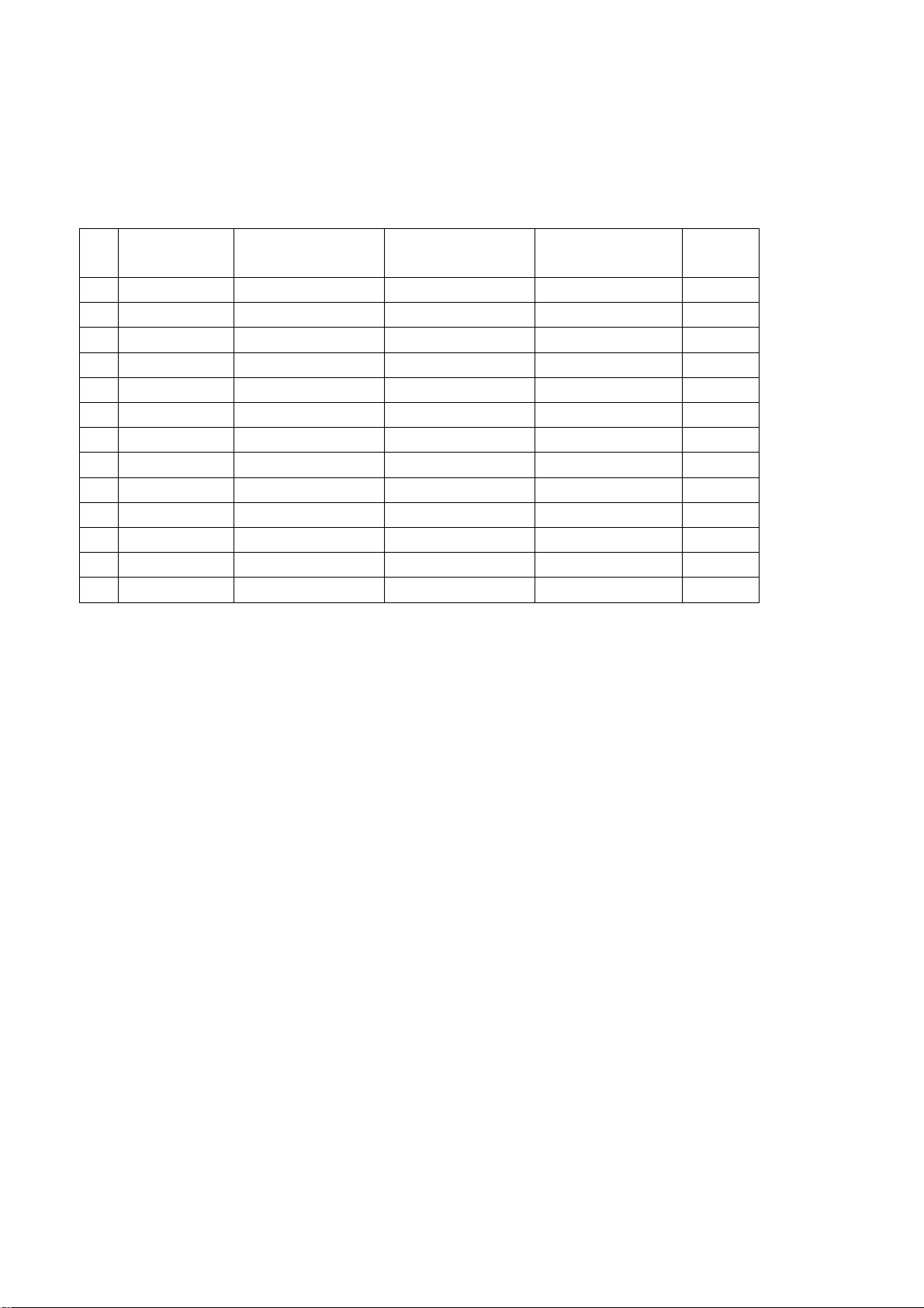
4.3 YPbPr/YCbCr terminal
Input YUV signal (VG-849 signal generator), separate input YUV format signal of table 1 and check
if the picture and sound are normal.
Table 1 YUV signal format
No H-frequency (KHz) V-frequency (KHz) Signal
1 15.734 59.94 SDTV 480i
2 31.469 59.94 HDTV 480p
3 44.955 59.94 HDTV 720p
4 33.716 59.94 HDTV 1080i
4.4 VGA terminal
Input VGA signal (VG-849 signal generator), separate input VGA format signal of table 2 and check
if the picture and sound are normal. If the image is deflection of the H-field, select manual correction
of Advanced Video Menu.
4
Page 7
4.5 HDMI terminal
HDMI signal format receives the three high-definition signals: 480I, 480P, 720P/60Hz, 1080I/60Hz,
except for the table 2 signal. Check if the image (contain HDCP ON and OFF) and sound are
normal.
Table 2 VGA signal format
No Resolution H-frequency(kHz) V-frenquency(Hz)
1 720 X 400 31.469 70.086 28.322 IBM
2 640 X 480 31.469 59.94 25.175 IBM
3 640 X 480 37.861 72.809 31.5 VESA
4 640 X 480 37.5 75 31.5 VESA
5 640 X 480 43.269 85.008 36 VESA
6 800 X 600 35.156 56.25 36 VESA
7 800 X 600 37.879 60.317 40 VESA
8 800 X 600 48.077 72.188 50 VESA
9 800 X 600 46.875 75 49.5 VESA
10 800 X 600 53.674 85.061 56.25 VESA
11 1024 X 768 48.363 60.004 65 VESA
12 1024 X 768 56.476 70.069 75 VESA
13 1024 X 768 60.023 75.029 78.75 VESA
Point clock pulse
frenquency(MHz)
Remark
4.6 YPBPR and TV brightness check (use 100IRE white window signal)
5 Ex-factory setting of user menu
1) Select TV channel, volume: 25
2) Video menu, Picture Mode: Nature, Aspect Ratio: Wide
3) Video menu, Advanced Video Menu:
Noise Reduction——Spatial: On
Noise Reduction——Speckle: Off
Noise Reduction——Temporal: On
Sharpness: 0
Tine: 50
Color Temperature: Cool
3D Y/C: On
4) Audio menu, Sound Mode: News, Balance: 31, Earphone Vo1:31
Digital Audio Output: AC-3, MTS: Mono
5) Setup menu, Tuning Band: Air
6) Feature menu, Sleep Timer: Off, Menu Language: English
Note: Except for Color Temperature of Cool, the Advanced Video Menu of YPBPR/YCBCR and
VGA channels sets according to the adjustment of factory.
Trouble shooting
Before servicing please check to find the possible causes of the troubles according to the table
below.
5
Page 8
1.Antenna(signal):
Picture is out of focus or jumping Bad status in signal receiving
Poor signal
Check if there are failures with the electrical connector or
the antenna.
Check if the antenna is properly connected.
Fringe in picture Check if the antenna is correctly oriented.
Maybe there is electric wave reflected from hilltop or
building.
Picture is interfered by stripe
shaped bright spots
There appear streaks or light color
on the screen
Possibly due to interference from automobile, train, high
voltage transmission line, neon lamp etc.
Maybe there is interference between antenna and power
supply line. Please try to separate them in a longer
distance.
Maybe the shielded-layer of signal wire is not connected
properly to the connector.
Check if interfered by other equipment and if interfered
possibly by the equipment like transmitting antenna, non
professional radio station and cellular phone.
2.TV set:
Symptoms Possible cause
Unable to switch the power on Check to see if the power plug has been inserted
properly into the socket.
No picture and sound Check to see if the power supply of liquid crystal TV has
been switched on. ( as can be indicated by the red LED
at the front of the TV set)
See if it’s receiving the signal that is transmitted from
other source than the station
Check if it’s connected to the wrong terminal or if the
input mode is correct.
Check if the signal cable connection between video
frequency source and the liquid crystal TV set is correct.
Deterioration of color phase or
color tone
Screen position or size is not
proper
Picture is twisted and deformed Check to see if the picture-frame ratio is properly set up.
Picture color changed or colorless Check the “Component” or “RGB” settings of the liquid
Picture too bright and there is
distortion in the brightest area
Check if all the picture setups have been corrected.
Check is the screen position and size is correctly set up.
crystal TV set and make proper adjustment according to
the signal types.
Check if the contrast setting is too high.
Possibly the output quality of DVD broadcaster is set too
high.
6
Page 9
Symptoms Possible cause
It maybe also due to improper terminal connection of the
video frequency signal in a certain position of the
system.
Picture is whitish or too bright in
the darkest area of the picture
No picture or signal produced from
the displayer if “XXX in search”
appears.
There appears an indication “outside the receivable scope)
Remote control cannot work
properly
No picture and sound, but only
hash.
Blur picture Check if the antenna cable is correctly connected.
No sound Check if the “mute” audio frequency setting is selected.
When playing VHS picture search
tape, there are lines at the top or
bottom of the picture.
Check if the setting for the brightness is too high
Possibly the brightness grade of DVD player
(broadcaster) is set too high.
Check if the cable is disconnected.
Check if it’s connected to the proper terminal or if the
input mode is correct.
Check if the TV set can receive input signal. The signal is
not correctly identified and VGA format is beyond the
specified scope.
Check if the batteries are installed in the reverse order.
Check if the battery is effective.
Check the distance or angle from the monitor.
Check if there is any obstruct between the remote control
and the TV set.
Check if the remote control signal- receiving window is
exposed to strong fluorescence.
Check if the antenna cable is correctly connected, or if it
has received the video signal correctly.
Of if it has received the right video signal.
Check if the sound volume is set to minimum.
Make sure the earphone is not connected.
Check if the cable connection is loose.
When being played or in pause VHS picture search tape
sometimes can’t provide stable picture, which may lead
to incorrect display of the liquid crystal TV, In this case
please press “auto” key on the remote control so as to
enable the liquid crystal TV set to recheck the signal and
then to display correct picture signal
7
Page 10
Method of software upgrading
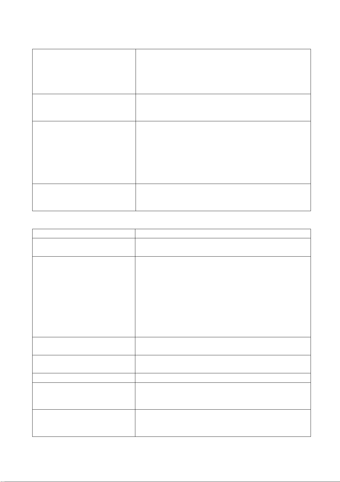
1. Connect computer serial port and TV parallel port with serial wire 665.D0002-645.
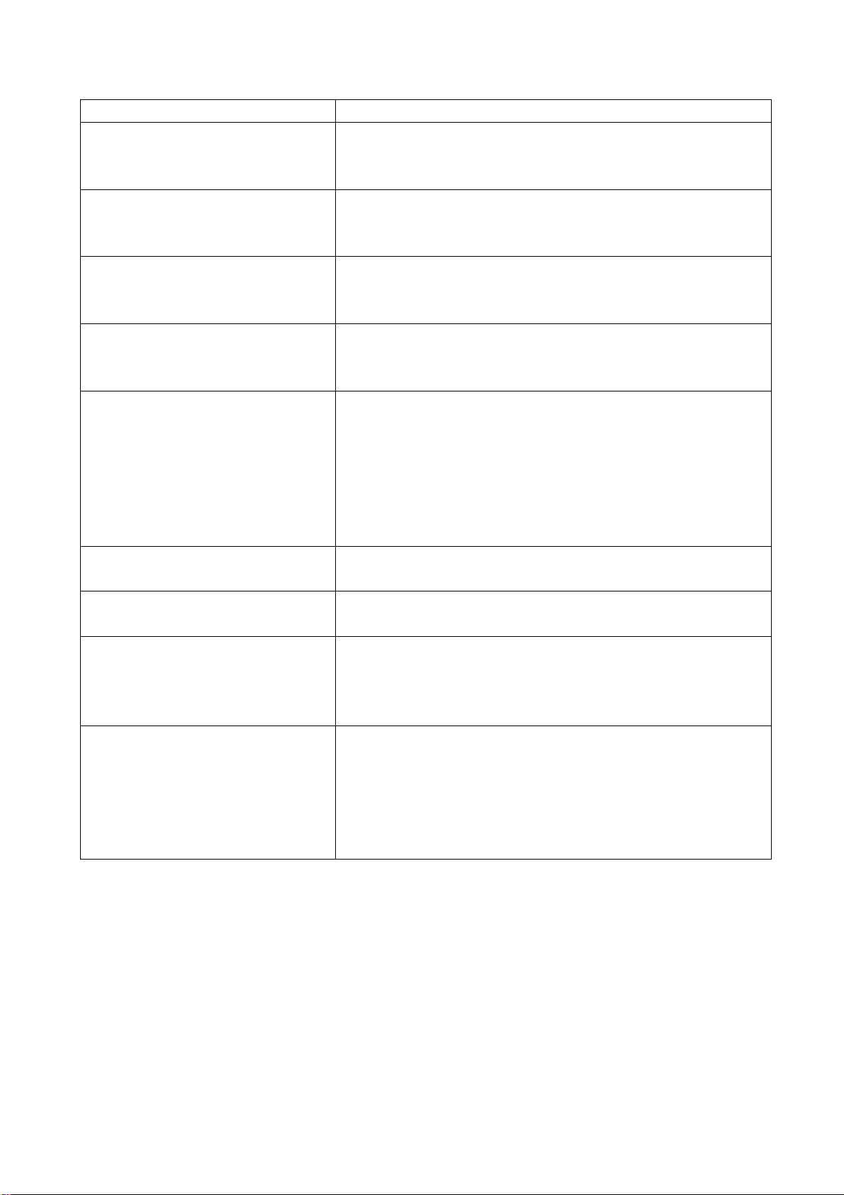
2. Open iDev.exe
3. Click
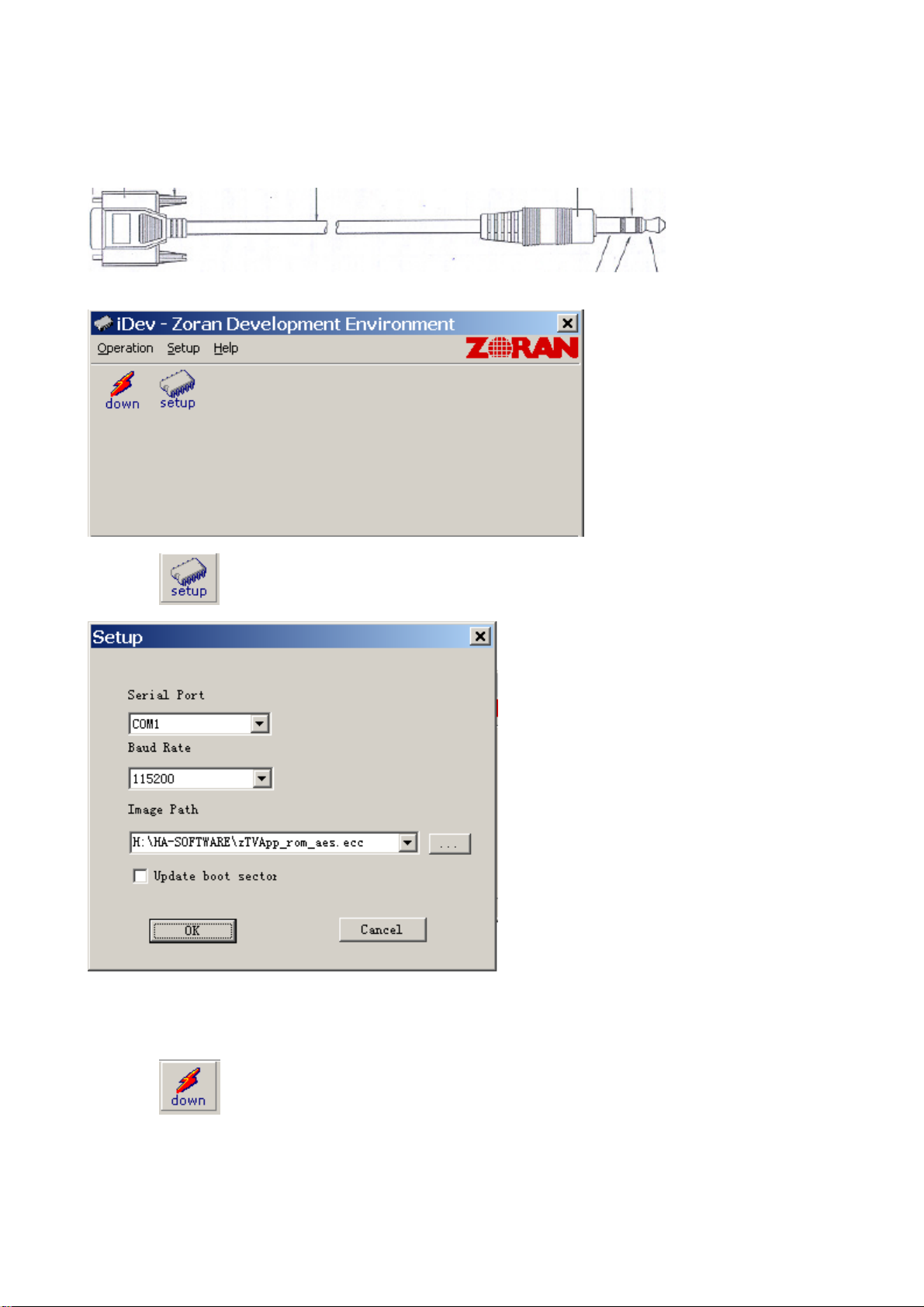
Set Serial Port to the current COM port, set the Baud Rate to 1152000, Image Path to the path of the
new software. If the new software renews Bootcode, pitch on “Update boot sector” option and then click
OK.
, enter the setting interface.
4. Click
to enter the interface below:
8
Page 11
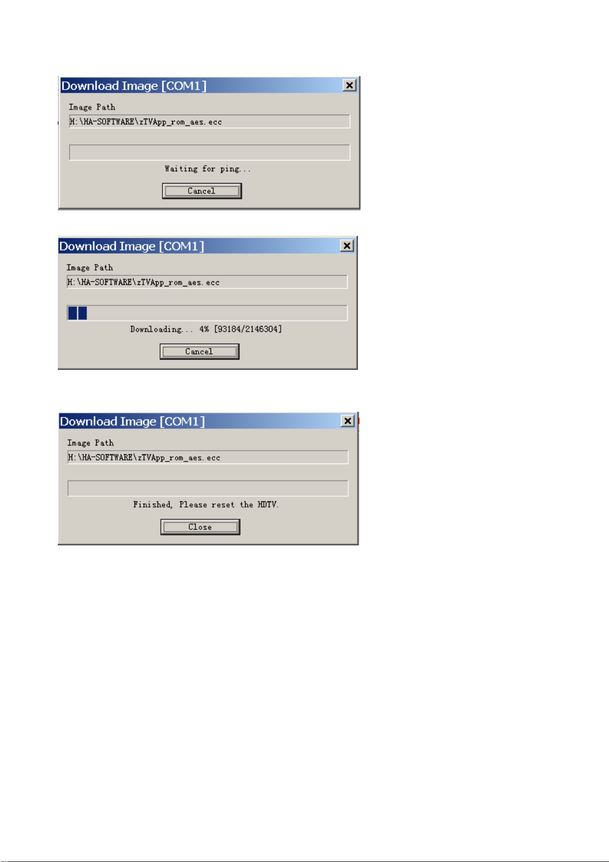
5. Turn on the TV, the software begins to be written.
6. After the software written, Press the power key (local keypad) and holding for several second to
force power off TV set,
7. Turn on the TV again and enter the factory menu initialization setting.
9
Page 12

Working principle analysis of the unit
1. NTSC signal flow:
Antenna reception NTSC signal send to the integrative tuner TDQDU4-508A, which contains HF
and IF amplifier circuit and video decoding circuit. It is controlled by main IC ZR39760 (integrate
CPU) through I2C bus. The NTSC signal via frequency tuning, HF amplification, IF amplification,
system switching and decoding, output video signal TV-CVBS of 1Vpp and sound IF signal (SIF).
TV-CVBS, AV1-CVBS, AV2-CVBS input from AV terminal and S-VIDEO via switch IC N52797EP to
output signal, one way send to ZR39760 for VEDIO DECODER, DEINTERLACE and SCALER,
then send to LVDS level drive for PDP screen, another way is output through AV output socket as
AV OUT.
The sound IF (SIF) is fed into demodulation IC ZR39760, via decoding and A/D conversion, it is fed
into ZR39760 for analog control in the format of I2S. ZR39760 outputs audio data of I2S format, it is
fed into audio D/A converter IC CS4344, output analog L/R signal. The L/R signal and sound signal
of PC/YPRPB via diverter switch HEF4052BT, send to R2S15903SP (sound processing and volume
control). Select right/left sound channel, their send to class D sound amplifier R2S15102 amplify,
then send to speaker.
2. ATSC signal flow:
Antenna reception ATSC signal send to tuner TDQU4-508A, after frequency tuning, HF
amplification, IF amplification and SAW FILTER, fed to ZR39760 for information source decoding in
the format of standard serial TS stream.
HD video signal via decoding to A/D conversion and OSD superposition, at last send to LVDS drive
level for PDP panel.
HD audio signal, via decoder built-in ZR39760, resumed to multi- channel sound of Dolby AC-3, at
the same time output data stream of I2S format and S/PDIF data stream. Audio data of I2S format is
fed to audio D/A converter chip CS4344 to output analog L/R signal. S/PDIF data stream directly
output from optical fiber interface.
3. PC/YPrPb signal flow
PC and two YPBPR signal via matched resistance, it a-c couple to video switch SN74CBT3257CDR,
via switching to selected signal to Triple Video A/D Converter MST9883 A/D conversion. Send
B/G/B of 24 bit to main IC ZR39760 digital decode, image scale and OSD superposition, then send
to LVDS level drive for PDP screen.
Sound signal (PC, YPrPb) via switch diverter HEF4052BT to output signal, it send to R2S15903SP
(sound processing and volume control) switch of audio. Select right/left sound channel, their send to
class D sound amplifier R2S15102 amplify, then send to speaker.
4. HDMI signal flow
HDMI video signal is directly fed to main IC ZR39760 (with HDCP function of HDMI) digital decode,
image scale and OSD superposition, then output LVDS drive level for screen.
HDMI audio signal via decoder built-in ZR39760, output data stream of I2S format and S/PDIF data
stream at the same time. Audio data of I2S format is fed to audio D/A converter chip CS4344 to
output analog L/R signal. S/PDIF data stream directly output from optical fiber interface.
10
Page 13

Block diagram
with
switch
earphone socket
KEY
PLC915
IR
PANEL
PC AUDIO
AV2
R2S15102
CD4052
R2S15903
I2S
CS5340
I2S
CS4345
ATSC DIFATSC DIF
NTSC CVBS
I2C
C
I2C
PW2300
CAT99
LVDS
ZR39760
83
SPI 32M Flash
SDRAM
DDR 256M
AV1
YPbPr Audio2
YPbPr Audio1
M52797SP
AV Audio Out
AV Out
ATSC/NTSC TNUER
11
Y
S Video
P15V
330
P15V
YPBPR1
YPBPR2
330
PC
FSHDMI04+PI5V330
MAX3232C
RS232
HDMI1
HDMI2
Page 14

IC block diagram
1. ZR39760
12
Page 15

2. MST9883
MST9883 is a Triple Video A/D Converter with Clamps & Pixel Clock Synthesizer. The triple ADC
support 12 - 110 MHz Sampling Rate. It integrated 5-bit pixel clock phase adjustment for precise
sample timing control. Its Output support 4:2:2 Format Mode and it can Pin Compatible with
AD9883A.
Block diagram of MST9883 is flow:
13
Page 16

14
Page 17

Pin configuration of MST9883:
Pin descriptions of MST9883:
54: Red analog input
48: Green analog input
43: Blue analog input
49: Sync on Green analog input
38: External Clamp Input
30: Horizontal SYNC Input
31: Vertical SYNC Input
29: Hold PLL Frequency, do not track HSYNC
56: Serial Interface clock
57: Serial Interface data pin
55: Serial interface address pin
70-77: Red output data
2-9: Green output data
12-19: Blue output data
67: Output data clock
66: HSYNC output
64: VSYNC output
39,42,45,46,51,52,59,62: Analog Power
15
Page 18

26,27,34,35: PLL Power
11, 22, 23, 69,78,79: Digital Output Power
1,10,20,21,24,25,28,32,36,40,41,44,47,50,53,60,61,63,68,80:Ground
3. R2S15903SP
R2S15903SP is an audio signal processor. It has MUTE and Volume/Tone control. It can support 5
input selector.
Pin descriptions of R2S15903SP:
5, 28: AV OUT INPUT L/R
2, 31: other channels
17, 18:I2C SDA/SCL
32: Power Supply
16
Page 19

4. RS15102
RS15102 is the high effective D type of power amplifier. The output power can reach 20W (10%
THD+N) with 8-Ω speakers, +18V power supply, eliminating the need for heat sinks.
Pin description:
1: audio-out, left audio output
15: audio-out, right audio output
11: audio-in, left audio input
5: audio-in, right audio input
14: mute1
17
Page 20

5. M52797SP AV switch with I2C bus control
Pin description:
1 VCC 9V 17 VIDEO OUT
2, 4 AV2 L R IN 19, 21 L R OUT
2 AV2 VIDEO IN 20 AV CVBS OUT
6 TV-CVBS IN 23 TUNER_IN
5, 7 Y Pr Pb1 L R IN 22, 24 TV L R IN
8, 10 Y Pr Pb2 L R IN 11, 12 SCL, SDA
18
Page 21

Wiring diagram
782.22HA37-0500
782.26HA37-690A
782.L20S21-0900
782.26HA37-2900
XB02
VIDEO-OUT
XP3
KEY
XP2
IR
XB03
RS232
X41 LVDS
XP5
XP1
XV2
RF
NB9
SP/DIF
XA21
HDMI-1
XA22
HDMI-2
XB5
X1
VGA
X102
Y P
B PR -1/2
XB01
VIDEO-IN
XB7
S
X109
XB3
XB1
XB2
XV1
X509
X508
X505
X506
X501
220V
Back light powe r
Powe r board
Logi c board
Hous ehold
Powe r
Spea ker
Tun er
Main b oard
Port
Port
Port
Port
Earphone
-Ter mi na l
Mag net rin g
Mai n board p ower
Amp lifie r power
Bac kligh t power
Bac kligh t contr ol
Bac kligh t contr ol
Mai n board p ower
Amp lifie r power
Amp lifie r outpu t
Interface board
Key boardIR board
AC po wer
19
Page 22

Troubleshooting guide
p
d
r
N
N
N
f
N
p
N
r
p
If the picture of each channel
is normal?
If the sound of each channel is
normal?
(1) abnormal picture
a) Failure with RA125, RA124 on the main board, which may lead to panel abnormal
b) A certain differential wire pair of LVDS of X41(RX0+/-, RX1+/-, RX2+/-, RX3+/-) is abnormal,
c) Failure with NA25, which may lead to loss of corresponding color from the gray degree
d) Failure with NA102,NB21 and their peripheral circuit, which may lead to picture abnormal of
e) Failure with N100 on the image processing board, which may lead to picture abnormal in all
Begin
Turn on the TV?
A green indicator
lights?
Ye s
Display picture?
Ye s
which may lead to lack of color or color splash.,
corresponding to the picture of channel HDMI.
PC, YPbPr and YCbCr.
channels.
o
o
o
o
o
Check if XP1 9# on the main board is 3.3V,
if it’s 0V, check the power supply of the
ower board.
Check if the pin3 of XP1 on the main boar
is high level(+5V)? if not, check the powe
board and NP2.
Check if the power supply of main board is
normal? Then check the power supply o
each IC, if the crystal starts, DDR clock is
correct?
Check the signal inputted from the channel to
in IC or IC and its peripheral circuit or the
output of LVDS is normal
Check if the signal inputted from the channel
to pin IC is normal or IC (R2S15903,
RS15102, CS5340, CS4345) and thei
eriphery are normal
20
Page 23

,
N
r
r
b
N
N
p
p
N
r
N
p
N
(2) no picture, no sound
Check the color of indicato
light
Check the powe
oard
o sound
Refer to (3) checking
rocedure
(3) with picture but no sound
With picture but no sound
Check if the voltage of sound amplifie
of XV2 in main board is normal?
Check if RV12, RV13 inputs
signals
Ye s
Check NV1 and its
eripheral circuit
o picture, no sound
Ye s
o picture
Refer to (4) checking
rocedure
Ye s
Blue
Check the output voltage of
sockets XP1
Power board problem
o
Check NV3/NV2/NB12
and their peripheral circuit
XV2
o
o
Check the power board
21
Page 24

(4) with sound but no picture
N
N
d
N
N
d
p
p
N
Ye s
If there is no picture
in all channels?
Ye s
Check N100 an
its peripheral circuit
(5) S-Video or AV no picture
Check if CB106 and CB49 input signals? (AV IN)
Check if LB7, LB8 input signals? (S-Video)
Ye s
Check if pin20 of NB8
outputs signals?
Ye s
Check N100, CB153 an
their periphery circuit
With sound but no picture
Display OSD MENU?
Ye s
Display LOGO?
o
Check if the crystal in data processing board starts,
DDR clock and DDR SDRAM are normal?
o
Refer to (6), (7), (8), (9), (10),
(11), (12) checking procedure
Check the power supply of N100
on the image processing board
o
Check N105/N106 and the circuit
from AV terminal to N104
o
Check NB8 and its
eriphery circuit
Ye s
Check the power supply of N100 (on digital
rocessing board) and DDR and their periphery.
o
22
Page 25

t
N
p
N
N
p
d
p
(6) NTSC channel no picture
Check if pin4 of TUN1 outpu
signals?
Ye s
o
Check if CB154 outputs
signals?
Check TUN1 power supply and
the peripheral circuit.
Ye s
Check N100 and its
eriphery circuit
(7) ATSC channel no picture
Check if pin20/21 of TUN1
output signals?
Ye s
o
Check if the crystal is
normal? If output signal?
Check TUN1 power supply and
the peripheral circuit.
Ye s
o
Check socket N100 and the
eriphery.
Check the crystal an
eriphery circuit.
Note :
The I2C bus line control of TUNER is switch through the bus line of N228, so after checking the power
supply and peripheral circuit of TUNER226, it is still no picture in NTSC and ATSC channel, please
check N228 emphatically.
23
Page 26

Troubleshooting guide of power supply board
N
p
f
N
r
NNN
N
N N N
(8)
a. No power supply
o power supply
Does AC voltage at C502
Y
Check if X501 FU501 is
roperly inserted?
Does DC voltage at C514
(300~385V)
Y
Check D501, R513, D502
Check if the 15V DC o
503 (pin12)
Y
Check N503 or peripheral
circuit
b. No DC voltage output
Supplementary powe
supply N502 has problem
o DC voltage output
Check if DC voltage of C550 is
3.3V(5V)
Check if DC voltage of V505 B
is 24V
Check if DC voltage of C541 is
12V
Y
Y
Check N502 or peripheral
circuit
Main board has problem, or
It didn’t send out high level
control signal
Check N503, T501 or D516
Y
Problem exits in FU502, or there is
shortage on the main board
24
Page 27

602. L37HA37-01
11
Page 28

602. 32HA37-01
602. 32HA37-01
602. 32HA37-01
602.L37HA37-01
11
Page 29

602.L37HA37-01
11
Page 30

602.L37HA37-01
11
Page 31

602.L37HA37-01
Page 32

602.L37HA37-01
11
Page 33

602.L37HA37-01
11
Page 34

602.L37HA37-01
11
Page 35

602.L37HA37-01
Page 36

602.L37HA37-01
11
Page 37

Page 38

Page 39

APPENDIX-A: Main assembly 9350HA3110
NAME NO.
Digital processing board
Key board
IR board
Interface connection board
Power filter board
Power board
Remote control
Panel
6HA0196910
6HU0670510
6HA0150910
6HA0082910
6FK0105110
6HA0182010
6010D01204
5205503204
MAIN COMPONENT AND IT'S NO.
N100
NV1
NV3
NB8
NA102
NA25
RC-D12-0D
PDP50X4P
ZR39760 (5273976001)
R2S15102 (5271510201)
R2S15903 (5271590301)
M52797 (5275279701)
MST9983 (5279983003)
FSHDMI04 (5270004002)
Page 40

APPENDIX: EXPLODED VIEW PH50X31
Page 41

PART LIST OF EXPLODED VIEW
NO. DESCRIPTION
1 front cabinet
2 panel
3 filter glass
4 upsh board (left)
5 upsh board (upper1)
6 upsh board (upper2)
7 push board (right)
8 connection of panel
9 analog board
10 CPU board
11 power switch bracket
12 key board
13 wall mounting bracket
14 back cabinet
15 back baffle
16 speaker back cover (left)
17 speaker back cover (right)
18 stand
19 speaker
20 IR board
21 power cord
22 main frame
23 decorative bar
24 push board (below1)
25 push board (below2)
Note: design and specifications are subject to change without notice.
Page 42

9350HA3110
Ver.1.0
 Loading...