

Page 1
LCD TELEVISION
LC-42/47HW36
Page 2

CONTENTS
Safety precautions………………………………………………………………………..…
Alignment instructions …………………………….…….…………………………………
Method of software upgrading……………………………………………………………..
Working principle analysis of the unit……………………………….………….………….
Block diagram…………………………………..………………………………….…………
IC block diagram………………………………………………………………………..……
Wiring diagram …………………………………………………………………………….
Troubleshooting guide ………………………………………………………………..……
Schematic diagram…………………………………………………………………………
APPENDIX-A: Assembly list
APPENDIX-B: Exploded View
1
3
9
11
12
13
23
24
32
Page 3

Note: This maintenance manual is intended only for the reference of the maintenance people.
Please pay attention to the following points before carrying out the maintenance work.
Safety precautions
1. Instructions
Be sure to switch off the power supply before replacing or welding any components or
inserting/plugging in connection wire Anti static measures to be taken (throughout the entire
production process!):
a) Do not touch here and there by hand at will;
b) Be sure to use anti static electric iron;
c) It’s a must for the welder to wear anti static gloves.
Please refer to the detailed list before replacing components that have special safety requirements.
Do not change the specs and type at will.
2. Points for attention in servicing of LCD
2.1 Screens are different from one model to another and therefore not interchangeable. Be sure to
use the screen of the original model for replacement.
2.2 The operation voltage of LCD screen is 700-825V. Be sure to take proper measures in
protecting yourself and the machine when testing the system in the course of normal operation or
right after the power is switched off. Please do not touch the circuit or the metal part of the module
that is in operation mode. Relevant operation is possible only one minute after the power is
switched off.
2.3 Do not use any adapter that is not identical with the TV set. Otherwise it will cause fire or
damage to the set.
2.4 Never operate the set or do any installation work in bad environment such as wet bathroom,
laundry, kitchen, or nearby fire source, heating equipment and devices or exposure to sunlight etc.
Otherwise bad effect will result.
2.5 If any foreign substance such as water, liquid, metal slices or other matters happens to fall into
the module, be sure to cut the power off immediately and do not move anything on the module lest it
should cause fire or electric shock due to contact with the high voltage or short circuit.
2.6 Should there be smoke, abnormal smell or sound from the module, please shut the power off at
once. Likewise, if the screen is not working after the power is on or in the course of operation, the
power must be cut off immediately and no more operation is allowed under the same condition.
2.7 Do not pull out or plug in the connection wire when the module is in operation or just after the
power is off because in this case relatively high voltage still remains in the capacitor of the driving
circuit. Please wait at least one minute before the pulling out or plugging in the connection wire.
2.8 When operating or installing LCD please don’t subject the LCD components to bending, twisting
or extrusion, collision lest mishap should result.
2.9 As most of the circuitry in LCD TV set is composed of CMOS integrated circuits, it’s necessary
to pay attention to anti statics. Before servicing LCD TV make sure to take anti static measure and
ensure full grounding for all the parts that have to be grounded.
2.10 There are lots of connection wires between parts behind the LCD screen. When servicing or
moving the set please take care not to touch or scratch them. Once they are damaged the screen
1
Page 4
would be unable to work and no way to get it repaired.
If the connection wires, connections or components fixed by the thermotropic glue need to
disengage when service, please soak the thermotropic glue into the alcohol and then pull them out
in case of dagmage.
2.11 Special care must be taken in transporting or handling it. Exquisite shock vibration may lead to
breakage of screen glass or damage to driving circuit. Therefore it must be packed in a strong case
before the transportation or handling.
2.12 For the storage make sure to put it in a place where the environment can be controlled so as to
prevent the temperature and humidity from exceeding the limits as specified in the manual. For
prolonged storage, it is necessary to house it in an anti-moisture bag and put them altogether in one
place. The ambient conditions are tabulated as follows:
Temperature Scope for operation 0 ~ +50 oC
Scope for storage -20 ~ +60 oC
Humidity Scope for operation 20% ~ 85%
Scope for storage 10% ~ 90%
2.13 Display of a fixed picture for a long time may result in appearance of picture residue on the
screen, as commonly called “ghost shadow”. The extent of the residual picture varies with the
maker of LCD screen. This phenomenon doesn’t represent failure. This “ghost shadow” may remain
in the picture for a period of time (several minutes). But when operating it please avoid displaying
still picture in high brightness for a long time.
3. Points for attention during installation
3.1 The front panel of LCD screen is of glass. When installing it please make sure to put it in place.
3.2 For service or installation it’s necessary to use specified screw lest it should damage the screen.
3.3 Be sure to take anti dust measures. Any foreign substance that happens to fall down between
the screen and the glass will affect the receiving and viewing effect
3.4 When dismantling or mounting the protective partition plate that is used for anti vibration and
insulation please take care to keep it in intactness so as to avoid hidden trouble.
3.5 Be sure to protect the cabinet from damage or scratch during service, dismantling or mounting.
2
Page 5

Alignment instructions
h
1. Alignment equipment
PM5515 (video signal generator)
VG-848/VG-849 (YUV, VGA, DVI/HDMI signal generator)
CA210 (white balancer)
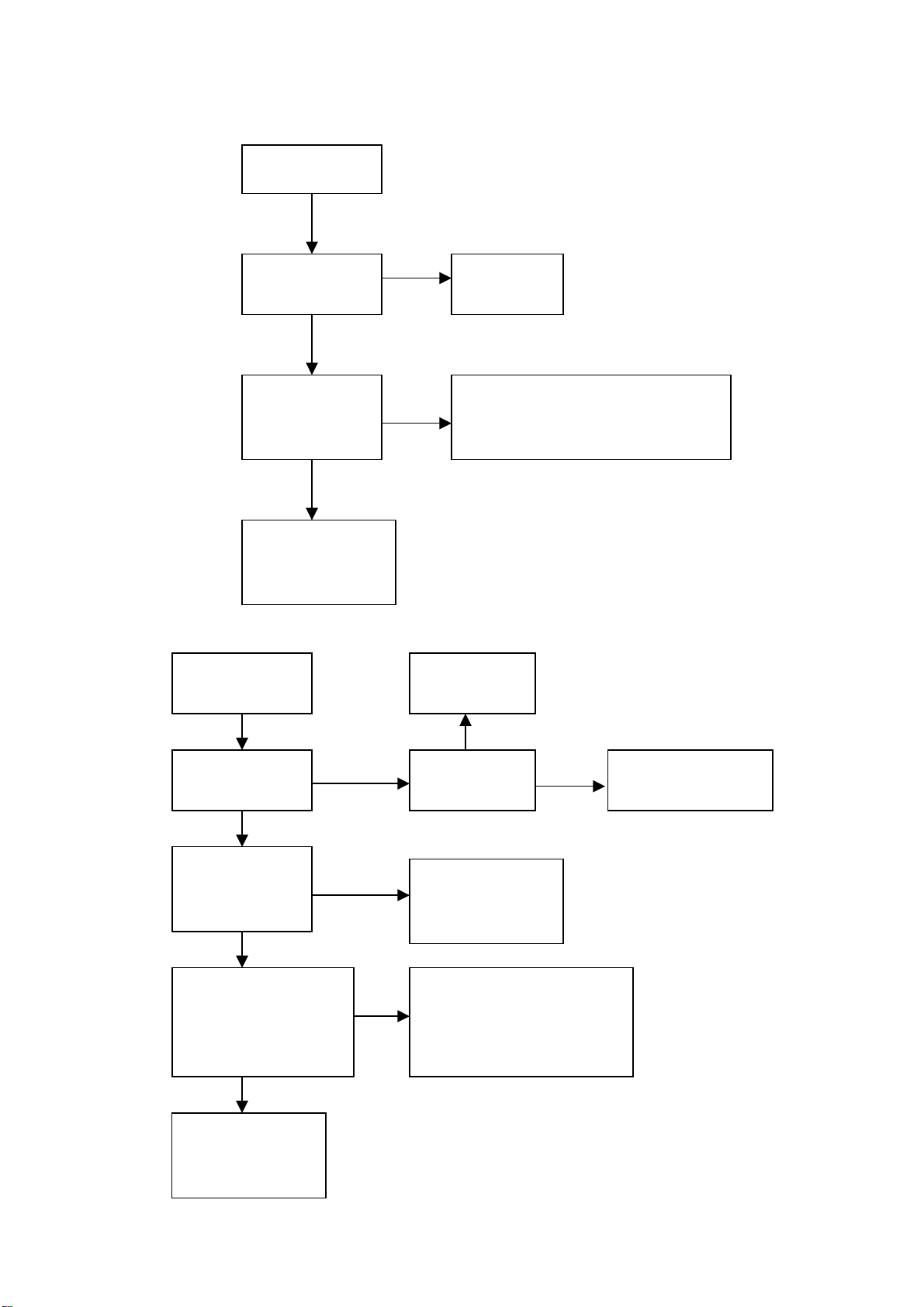
2. Alignment flow-chart
The alignment flow-chart is shown as fig-1
Connect with central signal source, then check each function of TV such as
station leaking, analog control etc., check the output of headphone and speaker
Input AV/SVIDEO signal, then check each function of all the terminals
Input VGA, HDMI signal, check if the display is normal, check eac
function such as analog control etc., check horizontal /vertical center etc.
3. Adjusting instruction
3.1 Unit adjustments
Connect all the boards according the wiring diagram, then power on and check if the display is
normal.
The method for using factory menu:
First press the “source” button, then press the “2580“ buttons to enter factory menu. Press the
“SLEEP” button to select the adjustment page menu, press ▲and ▼to select item, press ◄and ►
Check if DDC and FLASH are flash written
To produce digital board and analog board
All testing
White balance adjustment
Input HD signal then check each function of the terminal
Preset ex-factory
Check the accessories and pack them in box
Fig-1 adjustment flow-chart
3
Page 6

to adjust the value, press “MENU” button to exit the factory menu. If the unit does not turn off, you
can press the “SLEEP” button to enter factory menu again. Turn off the unit to exit the factory menu.
3.2 EEPROM initialization
Enter page one of the factory menu, select the EEPROM INITIALIZE to ON, turn off the unit then
turn on again.
Note: it needs a little long time to display the LOGO after turn on again.
3.3 White balance adjustment
The 16 level gray-scale signal (DVI:TIMING978 PATTAN921, HDMI:TIMING853, PATTERN992)
sends to DVI/HDMI channel from VG-848/VG-849, enter S.Magic sub menu of the user menu and
set “PWM” and “Sensor” to off, then enter the factory menu white balance adjustment page. Select
the normal color temperature item, fixed GGAIN to be 128, adjust B, RGIAN to let the third color
coordinate on the right be (280, 290 )at 400nits; fixed the GOFFSET to be 128H, adjust B,
ROFFSET to let the third color coordinate on the left be (280,290) at 5 nits.
Select the cool color temperature, adjust the color coordinate be (270, 283).
Select the warm color temperature, adjust the color coordinate be (300, 310).
After adjustment, switch to AV, VGA and YPbPr and have a check. If there is some deviation in
some channel, please adjust it independently.
Note: after adjust the white balance in HDMI, it will store the adjusted data to other channels.
4 Performance check
4.1 TV function
Connect RF-TV terminal to the central signal source and enter the setting menu, set the country
category, then enter the search menu → auto search, check if there is station skipping. Check the
manual search, fine turning, the output of speaker and earphone and picture. Open the PIP and
POP modes, connect the earphone and check the display and sound.
4.2 AV/S-video input terminal
Input AV/S signal, check if the picture and sound is normal. Open the PIP and POP modes, connect
the earphone and check the display and sound.
4.3 YPbPr /YCbCr terminal
Input the YUV signal (VG-848 signal generator), separate input YUV format signal of table 1, check
if the image and sound is normal. If the image is deflection of the H-field, select auto sync correction
of the SCREEN menu. If the image is slight disturb, adjust the FINE TUNE correction of the
SCREEN menu. Open the PIP mode, connect the earphone, and check if the image and sound is
normal.
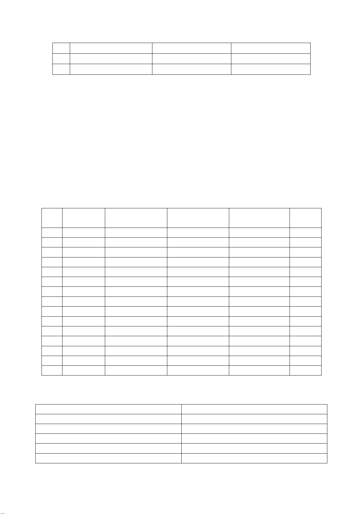
Table 1 YUV format signal
No H-frequency (KHz) V-frequency (KHz) Signal
15.734 59.94 SDTV 480i
1
31.469 59.94 HDTV 480p
2
44.955 59.94 HDTV 720p
3
33.716 59.94 HDTV 1080i
4
67.5 60 HDTV 1080P
5
15.625 50 SDTV 576i
6
31.25 50 HDTV 576p
7
4
Page 7
37.5 50 HDTV 720p
8
33.75 50 HDTV 1080i
9
56.25 50 HDTV 1080P
10
4.4 VGA terminal
Input the VGA signal (VG-848 signal generator), separate input VGA format signal of table 2, check
if the image and sound is normal. If the image is deflection of the H-field, select auto sync correction
of the SCREEN menu. If the image is slight disturb, adjust the FINE TUNE correction of the
SCREEN menu. Open the PIP mode, connect the earphone, and check if the image and sound is
normal.
4.5 HDMI terminal
HDMI signal format receive the three high definition signal: 480P, 576P, 720P/50/60Hz,
1080I/50/60Hz, 1080P/50/60Hz except for the table 2 signal. Check if the image (contain HDCP ON
and OFF) and sound is normal (use VG-849 generator). If the image is deflection of the H-field,
perform manual correction of the SCREEN menu. Open the PIP mode, connect the earphone, and
check if the image and sound is normal. Input DVI audio signal and check if it is normal.
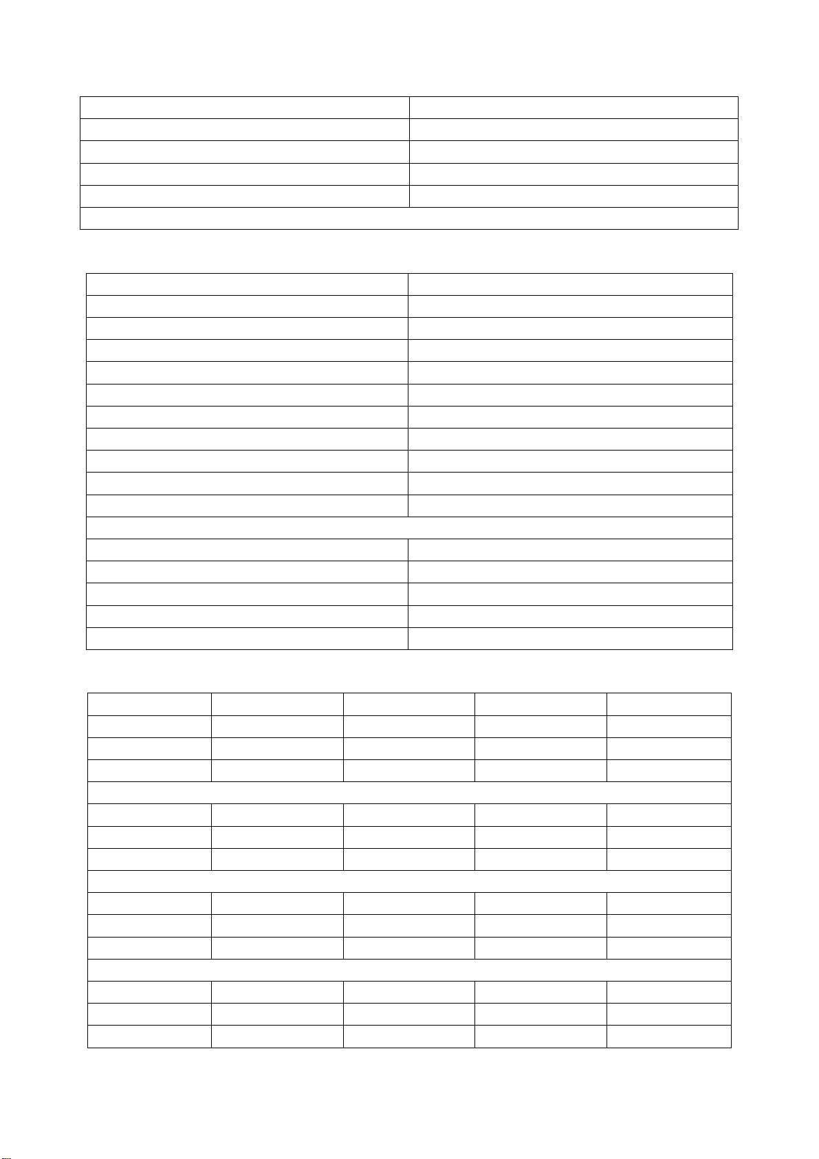
Table2 VGA signal format
No Resolution H-frequency(kHz) V-frenquency(Hz)
Point clock pulse
frenquency(MHz)
Remark
1 720x400 31.469 70.086 28.322 IBM
640x480 31.469 59.94 25.175 IBM
2
3 640x480 37.861 72.809 31.5 VESA
4 640x480 37.5 75 31.5 VESA
640x480 43.269 85.008 36 VESA
5
6 800x600 35.156 56.25 36 VESA
800x600 37.879 60.317 40 VESA
7
8 800x600 48.077 72.188 50 VESA
800x600 46.875 75 49.5 VESA
9
10 800x600 53.674 85.061 56.25 VESA
1024x768 48.363 60.004 65 VESA
11
12 1024x768 56.476 70.069 75 VESA
13 1024x768 60.023 75.029 78.75 VESA
14 1280x1024 63.98 60.02 108.00 VESA
15 1024x768 68.667 84.98 94.486 VESA
4.6 Ex-factory setting
Table3 Factory Option Menu
Item Setting
IIC Bus-off
Enter Update Mode
EEPROM Initialize Off
Backlight Adjustable Off
Back Light 0
5
Page 8
ShowLogo On
Hotel Mode Off
Direct Power On Off
Channel switch blank On
Preset Programs Off
Note: Back Light, Hotel Mode, Direct Power On have no function temporarily.
Table4 Factory Audio Setting
Item Setting
Volume 1 85H
Volume 25 B2H
Volume 50 C7H
Volume 75 D8H
Volume 100 ECH
Prescale_TV 42H
Prescale_Others 50H
Prescale_HDMI 78H
AIS_ADC_GAIN 05H
Main pic Hp F6H
HP VOLUME SETTING
Volume 1 50H
Volume 25 ABH
Volume 50 B9H
Volume 75 C7H
Volume 100 D6H
Table5 Factory Video Limit Setting
Item CVBS D-SUB YPbPr HDMI
Brightness Min 80H 60H 70H 70H
Brightness Mid 90H 80H 85H 90H
Brightness Max B0H A0H A0H B0H
Contrast Min 50H 70H 50H 50H
Contrast Mid 70H 90H 70H 70H
Contrast Max 85H B0H 85H 85H
Sharpness Min 40H 40H 40H 40H
Sharpness Mid 60H 60H 60H 60H
Sharpness Max 80H 80H 80H 80H
Color Min 00H 00H 00H 00H
Color Mid 40H 40H 40H 40H
Color Max 80H 80H 80H 80H
6
Page 9
Hue Min 00H 00H 00H 00H
Hue Mid 40H 40H 40H 40H
Hue Max 80H 80H 80H 80H
Table6 White Balance Adjust
Item CVBS D-SUB YPbPr HDMI
R Offset 119 119 119 119
G Offset 128 128 128 128
B Offset 123 123 123 123
R Gain 129 129 129 129
G Gain 128 128 128 128
B Gain 115 115 115 115
Color Temperature Standard
R Offset 120 120 120 120
G Offset 128 128 128 128
B Offset 121 121 121 121
R Gain 123 123 123 123
G Gain 128 128 128 128
B Gain 126 126 126 126
Color Temperature Cold
R Offset 118 118 118 118
G Offset 128 128 128 128
B Offset 126 126 126 126
R Gain 141 141 141 141
G Gain 128 128 128 128
B Gain 95 95 95 95
Color Temperature Warm
Table7 Picture Setting
CVBS Dynamic Standard Mild Custom
Contrast 90 80 50 50
Brightness 60 50 40 50
Colour 70 60 40 50
Tint 0 0 0 00
Sharpness 60 50 30 50
D-SUB Dynamic Standard Mild Custom
Contrast 90 80 50 50
Brightness 50 40 30 50
Colour 70 60 40 50
Tint 0 0 0 00
7
Page 10
Sharpness 60 50 30 50
YPbPr Dynamic Standard Mild Custom
Contrast 90 80 50 50
Brightness 50 40 30 50
Colour 70 60 40 50
Tint 0 0 0 00
Sharpness 60 50 30 50
HDMI Dynamic Standard Mild Custom
Contrast 90 80 50 50
Brightness 50 40 30 50
Colour 70 60 40 50
Tint 0 0 0 00
Sharpness 60 50 30 50
Note: You can set the value of the picture and sound mode at the factory menu. In other situation, the
changed value will be store in Custom mode.
Table8 Audio Setting
User Surround Music Movie
Treble 50 50 80 60
Bass 50 50 80 80
4.8 Ex-factory setting of user menu
1) select TV channel
2) video menu, Mode: Standard, colour temperature: nature
3) audio menu, Volume: 20, Balance: 00, Earphone volume:20, Mode: user, BBE: off, AVC: off
4) screen menu, Mode: Auto
5) station menu, Color mode: Auto, Sound mode: DK
6) setting menu, Child Lock: Off, Language: Chinese, OSD transparency :7, OSD time out: 15s,
Blue Screen: On.
Note: the 4) and 5) items should be set according to clients require. The user menu may be different
depending on the clients.
8
Page 11
Method of software upgrading
1. Software install instrument
a) Double click “PXSDKToolkitV1.0.5” to install the upgrade flat.
b) Execute “ISPWriter3.exe” to enter IAP program.
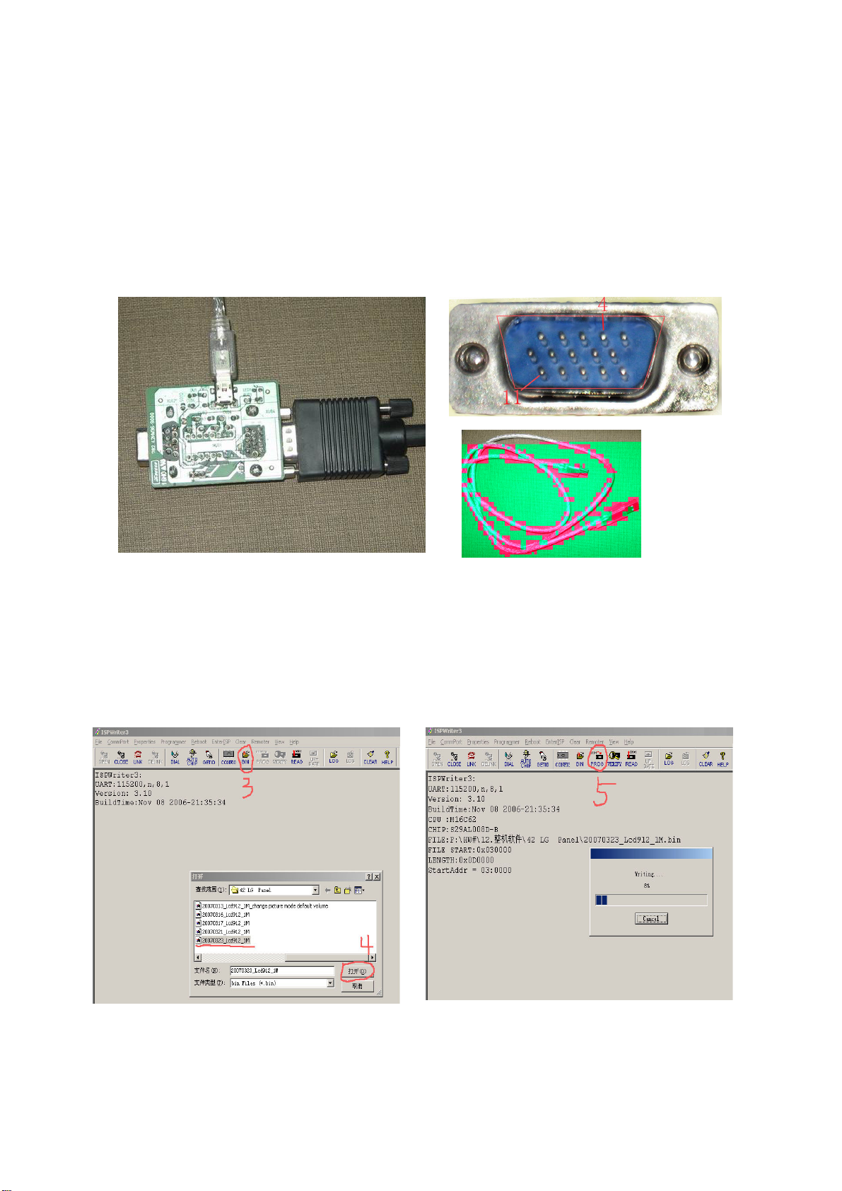
2. Instrument
Upgrade board (667.42HW36-90), USB wire (one male terminal and one mini terminal), VGA
cable(665.D0002-510 with pin4 and pin11).
3. Upgrade method when the unit is normal
a) Click “ISPWRITER3” icon on the desk to open the upgrade software, click “OPEN” of the
tool bar to begin communication, enter the factory menu and select “Enter Update Mode” of
the first OSD page to enter the upgrade mode.
b) Click “BIN” of the tool bar and select the upgrade software, click “PROG” on the tool bar to
begin upgrade.
3. BIN 5. PROG
4.
Select the upgrade software
9
Page 12
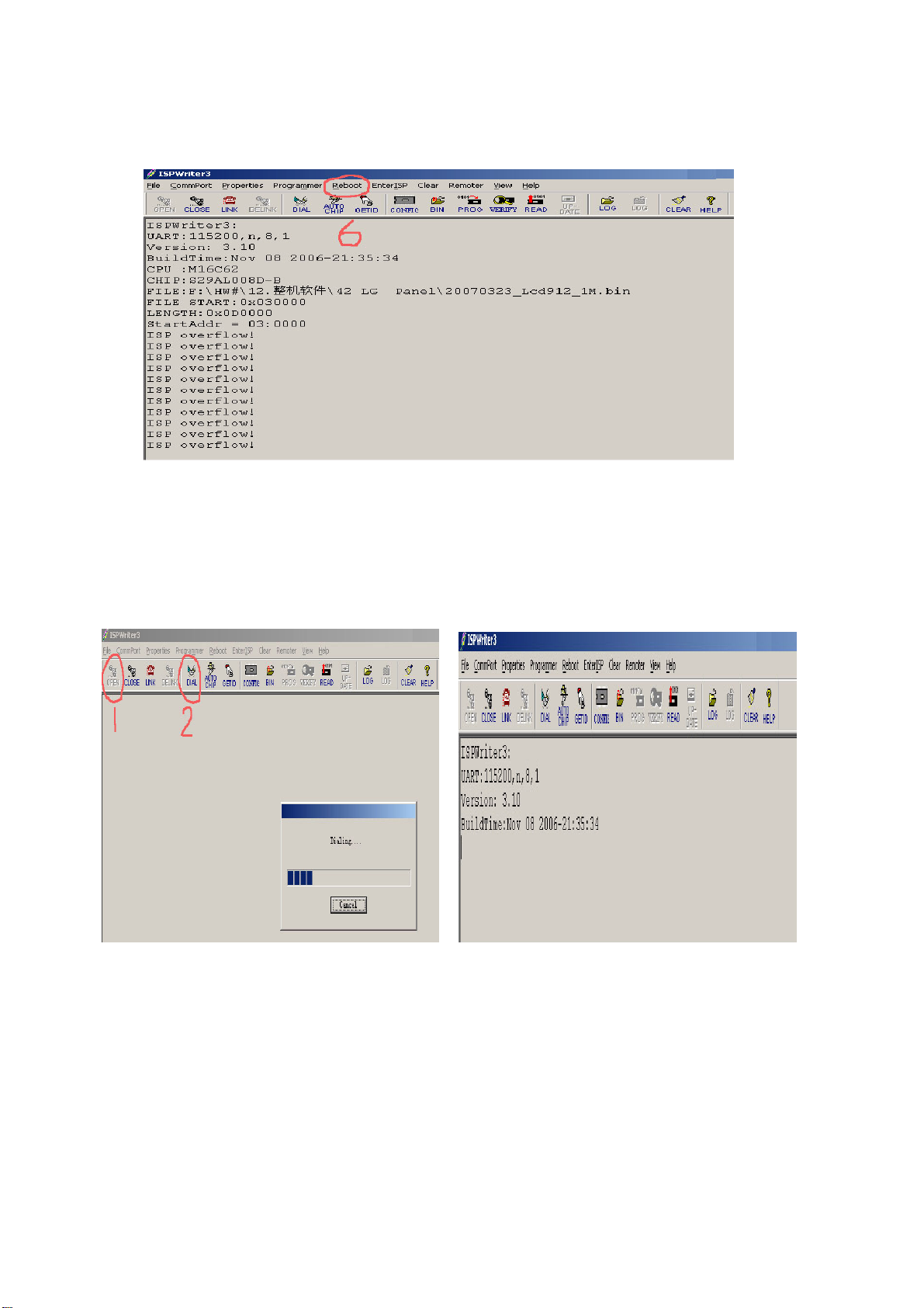
c) The upgrade is over when appear “ISP OVERFLOW”, click “Reboot” of the tool bar to
start-up the unit, then the upgrade is complete.
6. Reboot
4. Upgrade method when the unit can’t power on normally.
Click “ISPWRITER3” icon on the desk to open the upgrade software, click “OPEN” on the tool bar
to begin communication, then click “DIAL” on the tool bar to test the state of the unit, power on the
unit now to enter the upgrade automatically, then perform according 3), 4).
1. OPEN 2. DIAL
10
Page 13

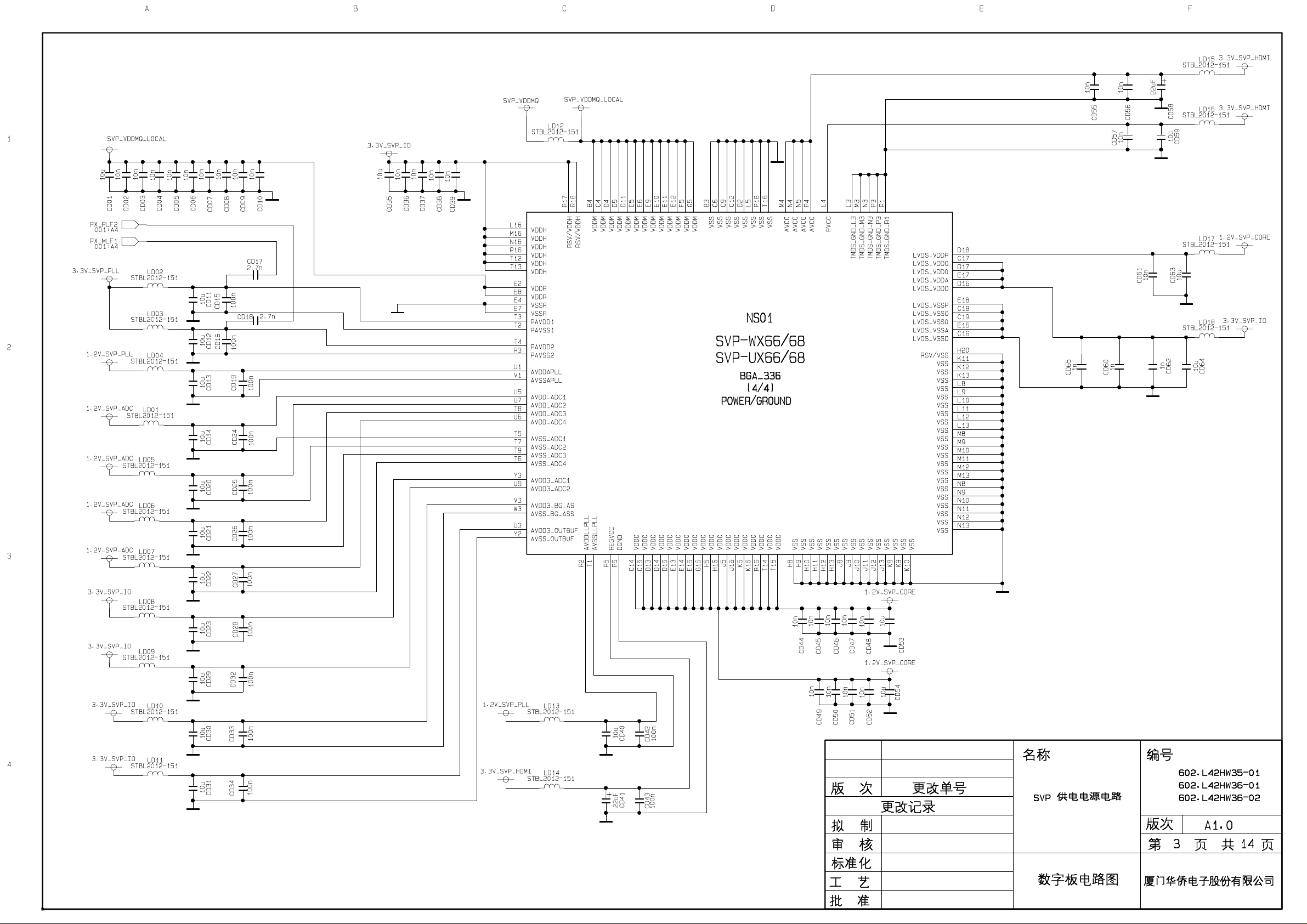
Working principle analysis of the unit
1. Analog signal
Antenna reception signal RF will be sent to integrative tuner (contain HF and IF amplifier circuit), the
tuner is controlled by the command (SDA and SCL) of the MCU N801(M16C), select appropriate
channel to system switch, via HF amplifier and IF amplifier decode, output video signal CVBS and
second sound signal SIF.
AV1, AV2 audio signal(AV1 and S-Video share the same audio channel), YPbPr1, YPbPr2 audio
signal, D-SUB/DVI audio, USB/PVR audio, HDMI and SIF are sent to N103(SGTV58xy audio
process and volume control) for audio switch, the selected audio signal is separated into left and
right channel and sent to digital audio amplifier N106(TPA3120) to amplify, then sent to speaker.
CVBS, AV1, AV2, S-Video signal (Y signal of S-Video and AV1 video share the same channel), USB
or YUV signal of PVR mode and D-SUB signal via matched resistance, the signal separately
through alone channel send to main IC NS01 (SVP-WX68) video switch, A/D transition, digital
decode, image scale and OSD superposition, then send to LVDS level drive for LCD screen.
Video signal of YPbPr1, YPbPr2 via matched resistance to video switch NB05 (PI5V330), after
switch the select signal will be sent to main IC NS01 (SVP-WX68) video switch, A/D transition,
digital decode, image scale and OSD superposition, then send to LVDS level drive for LCD screen.
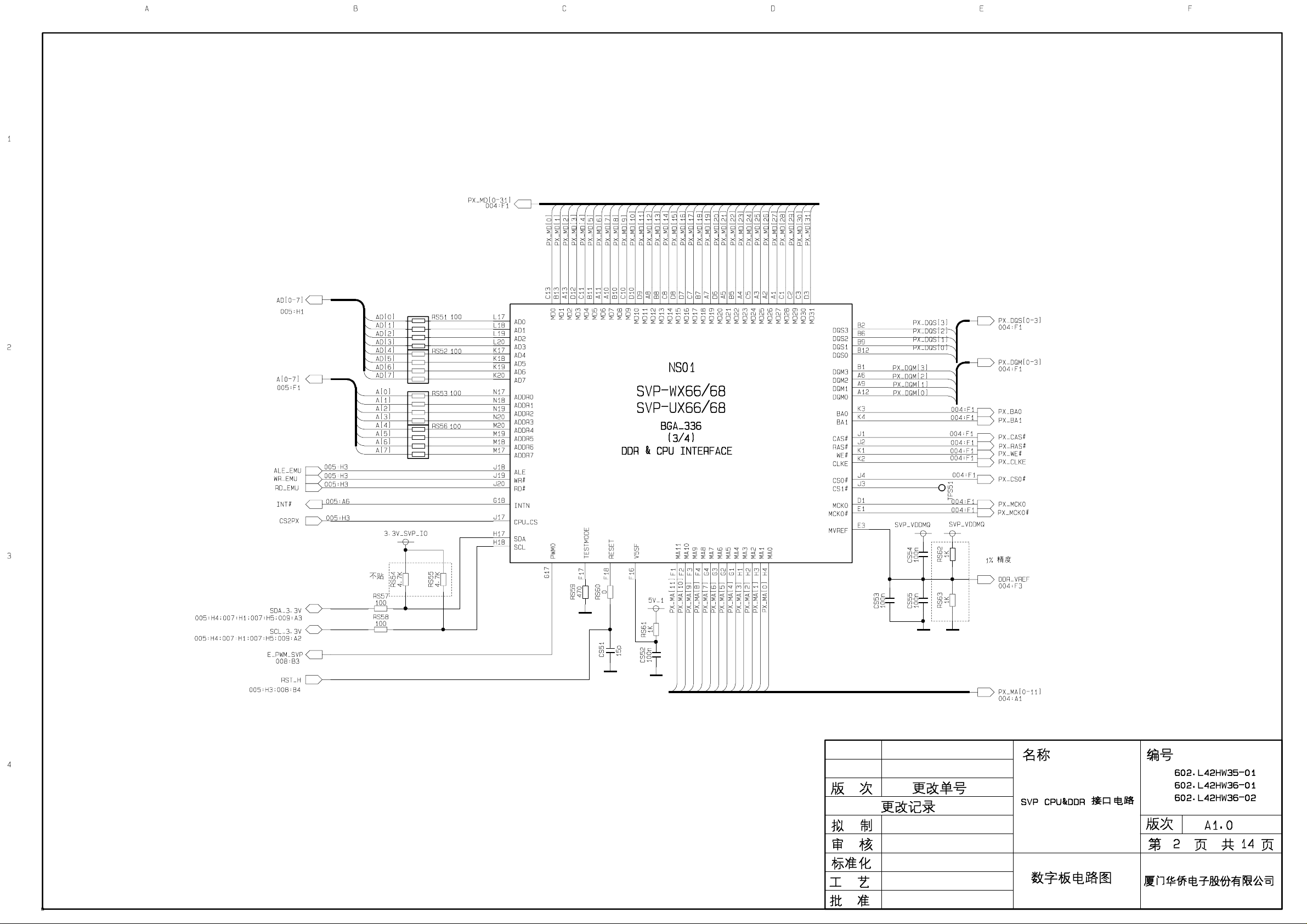
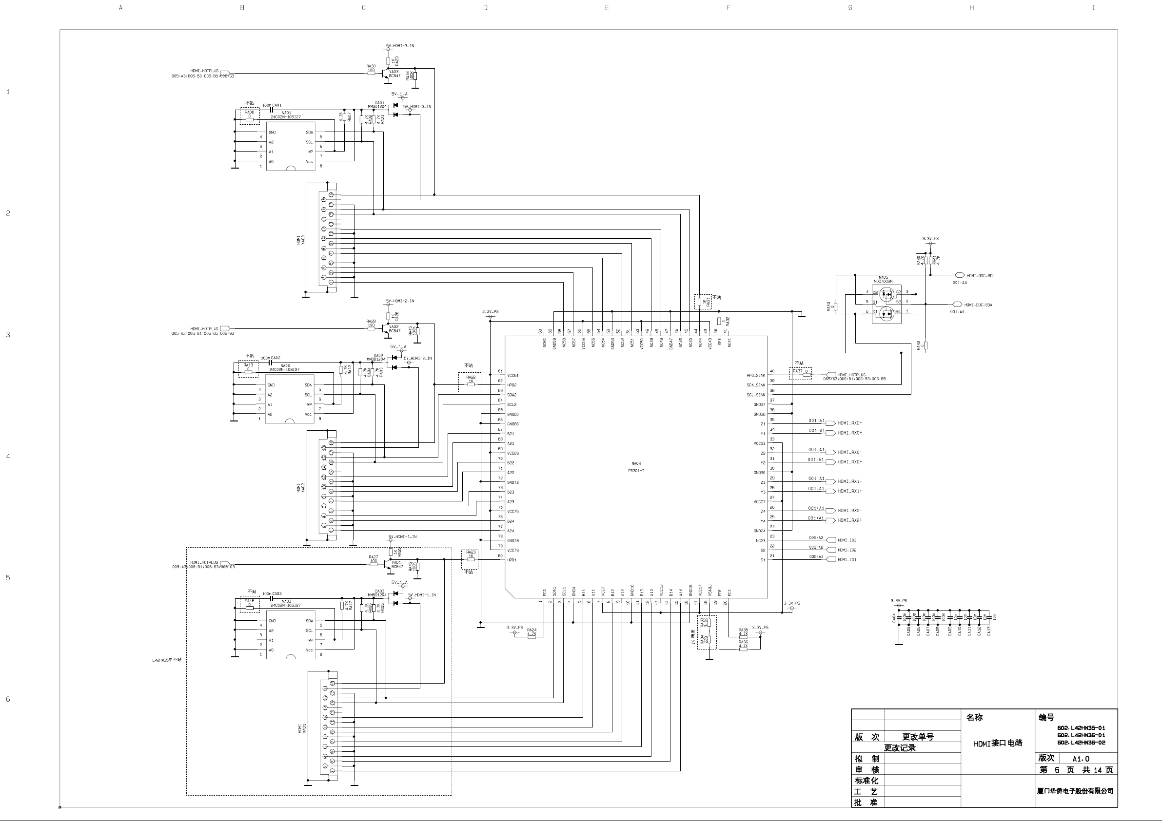
2. Digital signal
HDMI1, HDMI2, HDMI3 digital signal via digital video switch NA04(PS301), select one signal to
send to main IC NS01 (SVP-WX68) video and audio separate first, video signal via digital decode,
image scale and OSD superposition to output LVDS level drive for LCD screen; digital audio signal
I2S will be sent to N103 (SGTV58xy audio process and volume control).
11
Page 14
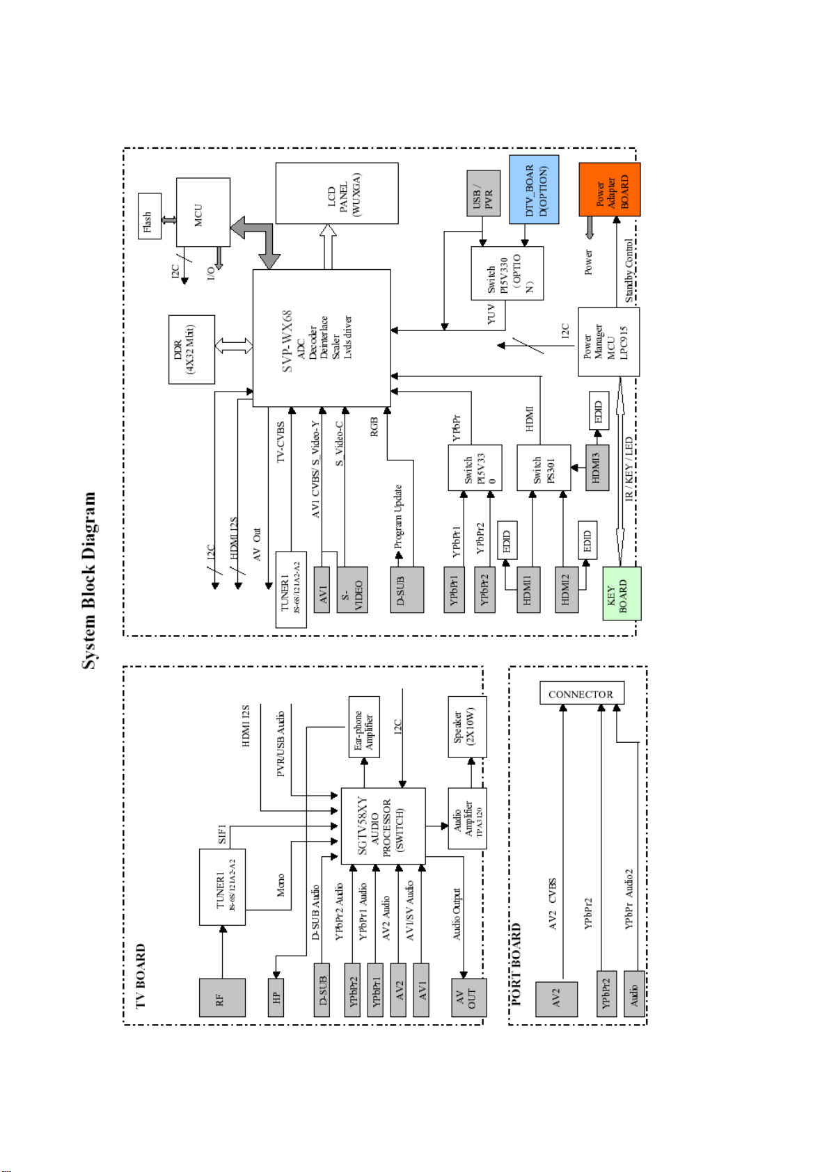
Block diagram
12
Page 15
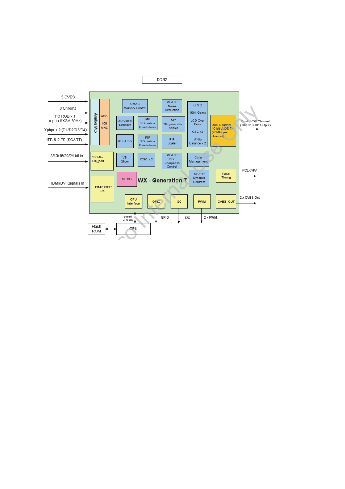
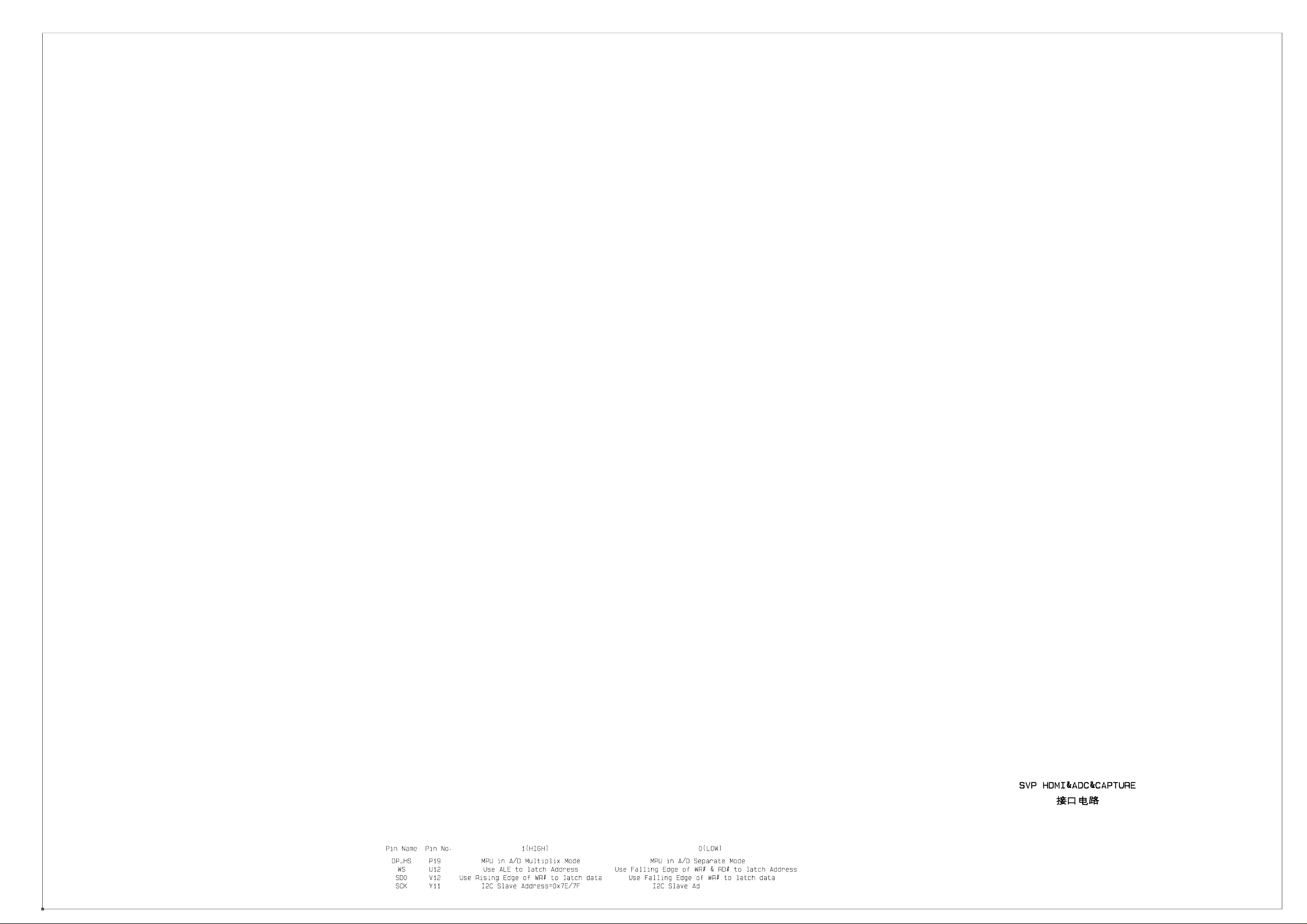
IC block diagram
1. DPTV-SVP-WX68
32bit 256MHz
Video signal from TUNER1, AV, RGB signal, Y and C signal, YUV, YPbPr signal via matched
resistance, the signal separately through alone channel send to main IC NS01(SVP-WX68) video
switch, A/D transition, digital decode, image scale and OSD superposition, then send to LVDS level
drive for LCD screen.
It can realize the functions of PIP, POP and Multi-window in N101.
13
Page 16
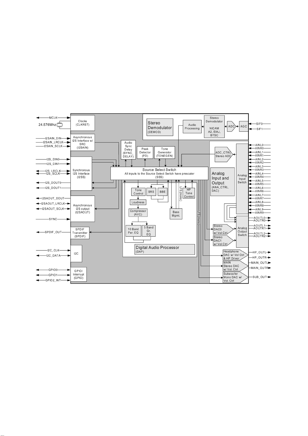
2. SGTV58xy
Audio signals and SIF are sent to N103(SGTV58xy) for stereo decode and AVC. SGTV58xy has ten
input channels for analog audio, audio of AV1. AV2 (AV1 and S-Video share the same audio
channel),YPbPr1, YPbPr2, D-SUB/DVI, USB/PVR are sent to N103, the signals are switched inside
the IC by the control of the software, the selected audio output through three ways. One way via
volume, treble and bass control, sound effect processing, then separate to left and right channel
and send to digital sound amplifier N106(TPA3210) amplifying, then send to speaker; one way also
separate to left and right channel and send to earphone amplifier N104(NJW1109) for volume
control and amplify, then send to earphone socket; the other way send to AV OUT.
Pin Description
92, 93: SDA, SCL
37, 38: left/right channel output to sound amplifier
34, 35: left/right channel of earphone
32, 33: AV OUT (right/left)
43, 44: USB audio (right/left)
51, 52, 47, 48: YPbPr 1,2 audio (right/left)
53, 54, 49, 50: AV IN (right/left)
57, 58: VGA audio (right/left)
59, 60: TV MONO
81: TV SIF input
14
Page 17
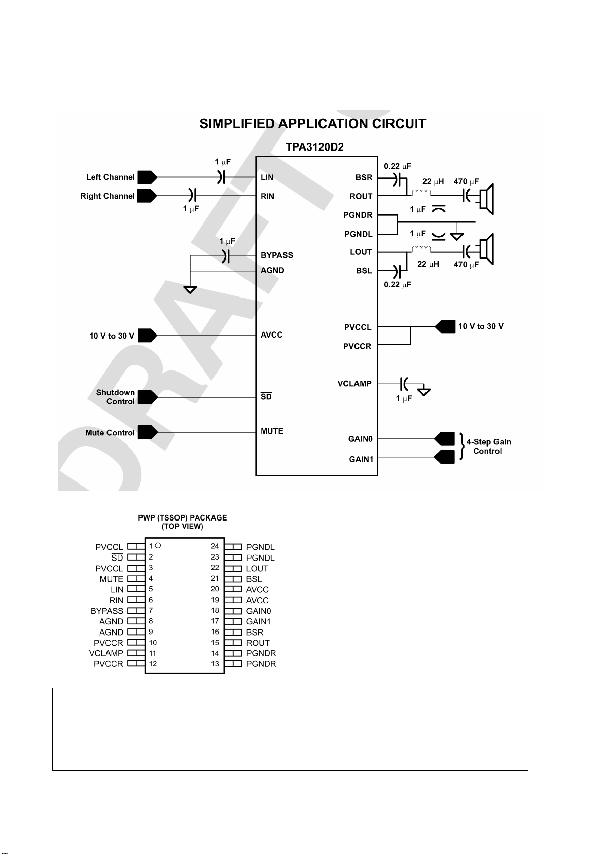
3. TPA3120
The TPA3120 is a 25-W stereo class-D audio power amplifier.
Pin Description Pin Description
2 Standby control signal input 17, 18 Gain select for audio output
4 Mute signal input 15, 22 Audio output for left/right channel
5, 6 Audio input for left/right channel 13, 14 Power ground
8, 9 Analog ground 19, 20 Power
15
Page 18

4. USB mode
To printer
AML7213
The AML7213 is an integrated system for multi-audio/video decoding, witch supports MPEG-1, MPEG-2,
MPEG-4 format. It has dual USB2.0 high-speed OTG ports that connect to digital camera, MP3 player
and other electric device. The AML7213 receives IR signal and supports YPbPr720P output and is used
for CRT, LCD, PDP, portable media players, etc.
16
Page 19

Pin description:
r
m
f
r
t
r
f
N
y
m
N
No N
N
INPUT:
PIN162 DP2 D+ signal input of USB2
PIN163 DM2 D- signal input of USB2
PIN173 DP1 D+ signal input of USB1
PIN174 DM1 D+ signal input of USB1
PIN189 IR input
OUTPUT:
PIN9 Pr
PIN12 Y
PIN15 Pb
PIN197 / PIN200 / PIN201 / PIN202 I2S audio output to NU8(CS4334)
OTHERS:
PIN51 / PIN52 crystal 27MHz
PIN185 I2C DATA
PIN186 I2C CLK
PIN208 power on reset pin for main IC
PIN168 OTG symbol of USB1, which indicate the situation of HOST or DEVICE, low level for
HOST and high level for DEVICE.
AML7213 trouble diagnosis
(1) no picture:
Please check firstly if the trouble is cause by the upgrade software, if YES, check if the upgrade
software matches to the main IC, because the three kinds of versions of AML3428, AML3278 and
AML7213 are not compatible. The module can’t work correctly with wrong version software and it
can’t upgrade the software through the USB port. You should unsolder FLASH and flash write the
new software through the flash write instrument.
Make sure the software is right and then check below:
Check if the
input powe
(5V) is normal
o
Remove the power (5V) fro
USB board and check if 5V o
output port is normal
Check 5V powe
output and 5V inpu
of USB board
Ye s
Check if 5V powe
of USB is short
Ye s
Check i
AML7213 12#
output Y signal
normally
o
Check if SDRAM
(NU3) 38# has
108M sine wave
1, NU3 and NU4 ma
o
abnormal, replace the
when the power supply is
normal
Yes Ye s
17
Page 20
t
N
t
t
V
p
p
N
No No N
Check the back level
circuit of IC outpu
(short or joint soldering)
1 is abnormal, replace i
when the power supply is
normal
(2) picture and operation are normal, but sound is abnormal:
Check if NU8 5# 8#
output sound signal
Check if NU8
7# has +5
ower supply
Ye s Yes
Check the
ower supply
Check if the back level
circuit of NU8 outpu
is short or open
Check if NU8 pin1-4
input high-low level
digital signal or sine wave
Ye s
o
Replace
1
Replace NU8
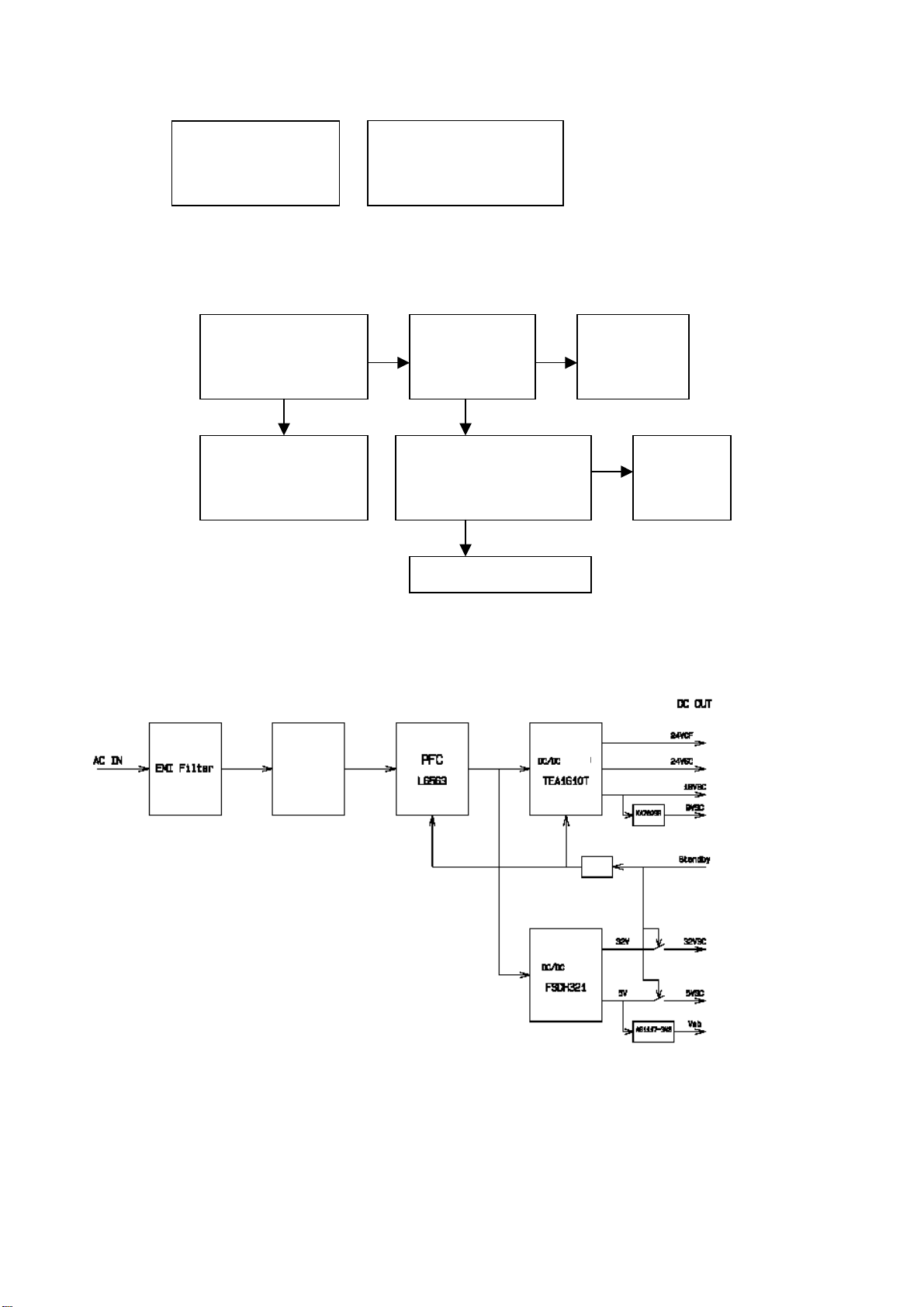
5. Power mode
The unit adopt PHILP power manage IC, which can control the power and the power consumption
is lower than 1W at stand-by and it has the function of timer setup.
backlight
Rectify
isolation
isolation
isolation
amplifier
Working principle of power:
The input AC power via EMC filter and rectification circuit, it sent to PFC(power factor correct L6563)
to output DC400V, which will be separated into two ways, one way via standby circuit (isolation D/D
convert FSDH321) output 5V and 32V; another way via semi-bridge circuit(TEA1610T) output 24V,
18V, etc. At standby, power board send out Vsb(3.3V) to cut off 5VSC, 32VSC output by the control
of Standby signal and stop working of PFC circuit(L6563) and semi-bridge (TEA1610T). When turn
18
Page 21
on, it makes all the IC working and output voltage.
L1653:PFC( power factor correct)
TEA1610T: Isolation D/D convert (400VDC converted to DC 24V, 18V, etc.)
FSDH321: Isolation D/D convert (400VDC converted to DC 5V, 32V, etc.)
FSDH321 block diagram is bellow:
19
Page 22
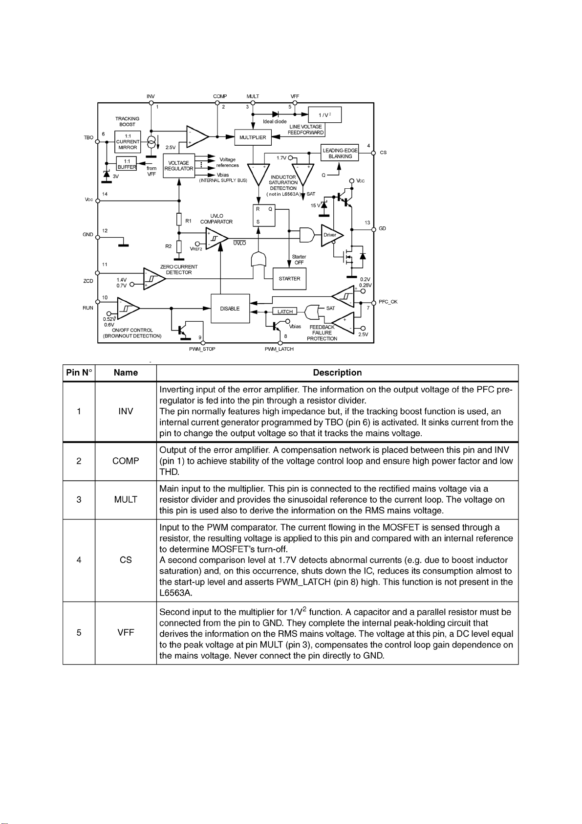
L6563 block diagram is below:
20
Page 23

21
Page 24
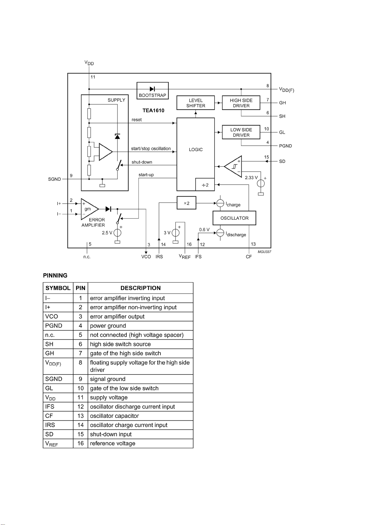
TEA1610T block diagram is below:
22
Page 25
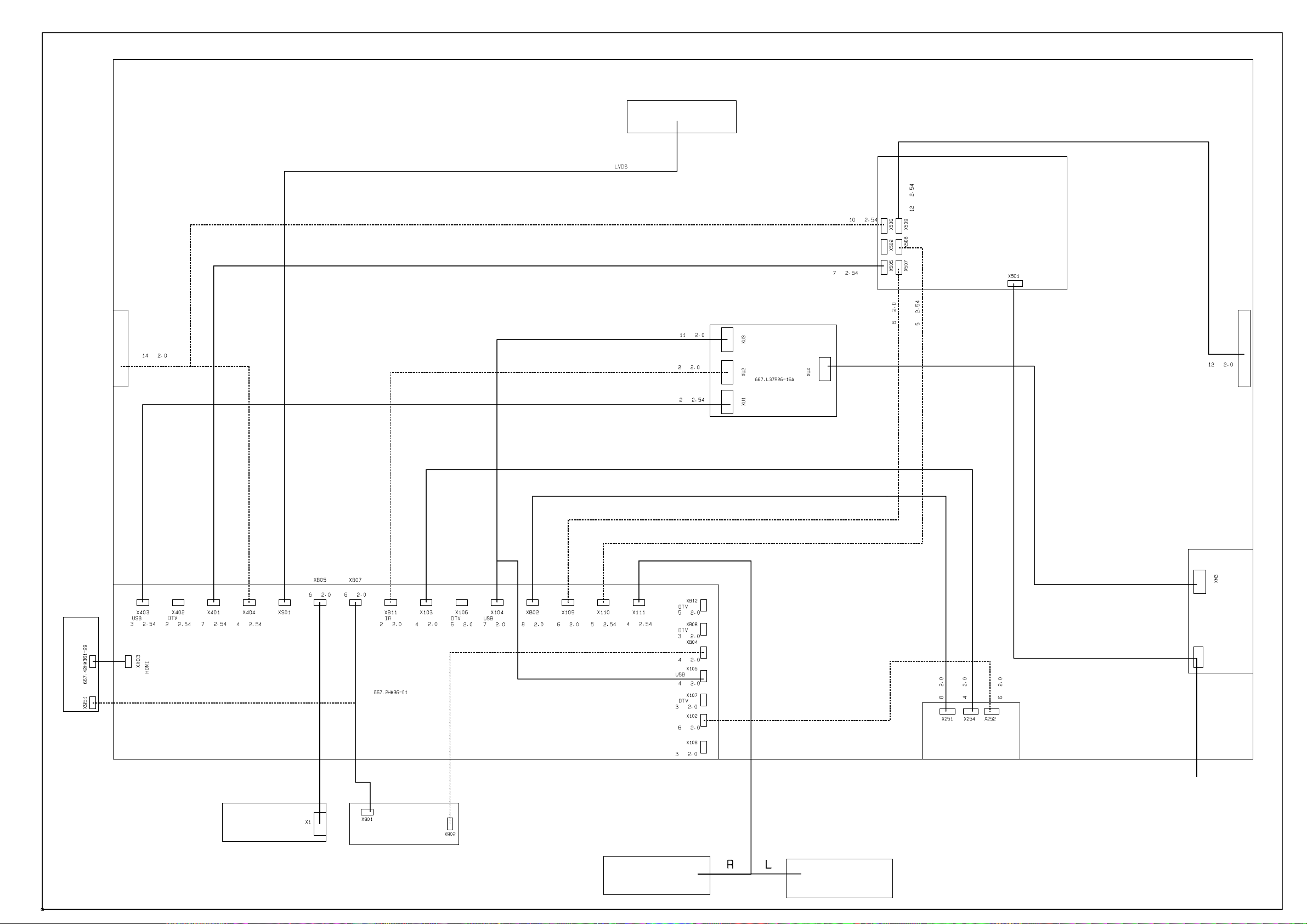
backlight
power board
backlight power
pin
pin
backlight power
main board power for digital circuit
pin
pin
pin
pin
amplifier power
power
pin
socket
side AV board
pin
power
side key board (option)
power board backlight control
pinpin
pin
touch key IR key
pin pin
real-time clock
pin
pin
main board
USB module
pin
pin
main board power of analog circuit
pin
backlight
control
video
pin
video
video interface
pinpin
power board amplifier power
pin
pin
speaker port
pin
pin
adjust
pin
sensor
pin
audio
pin
audio
pin
audio of video board
pin
side earphone
pin
video
pin
pin
audio
pin
video interface board
ISB board
power cord
KEY
IR
speaker
speaker
Page 26

Trouble shooting guide
r
r
N
N
N
h
N
p
N
Yes, turn the unit on
Check if the picture of eac
channel is normal?
Check if the sound of each
channel is normal?
Power on
A red indicato
lights?
A blue indicato
lights?
Ye s
Panel is light
on?
Ye s
o
o
o
o
o
Check power board, IR board, power manage
IC N601(P89LPC915) and power cord
Check if CPU 42#, FLASH 26# is square
wave? Check the peripheral circuit of CPU
and FLSH/EEPROM.
Check the backlight board, CPU 72#
backlight control.
Check the signal inputted from the channel to
in IC or IC and its peripheral circuit or the
output of LVDS is normal
Check if the signal inputted from the channel
to pin IC is normal or IC
(SGTV58xy/TPA3120) and its periphery is
normal.
24
Page 27

r
1.No raster, no picture, no sound
b
d
r
N
N
N
f
t
p
N
t
t
N
N
N
Check if the indicator is
blue?
o
Yes
Check the powe
control IC
Check CPU (N801),
FLASH (N802) powe
supply.
Abnormal
Check periphery o
L801, CPU and FLASH
Check if N801 42#, N802
26# is square wave
o
Check N801 crystal
and N806
No raster, no picture, no sound.
Check if the power supply indicator light is on?
Indicator is on
ormal
Check if CPU 10# (rese
in) is high level?
Yes
Check the periphery of N801,
802, N803 and N806
Indicator is off
Yes
ormal Abnormal
Check power
manage IC
o
Check N801 and its rese
circuit, if CPU is rese
correctly
Check standby
3.3V
Cut off the connection
etween power board
and digital board, an
test Standby-3.3V
ormal
Abnormal
Power board
has problem
25
Page 28

Note: when check N801(CPU) pin10 is low voltage, you may disconnect R616 and test if V603
p
p
d
NoN
collector output low voltage first, then output high voltage all the while (the low voltage is CPU reset
signal, it turns to high voltage when working normally), if not, it’s power manage IC problem. Is there
square wave in FLASH pin26? If not, disconnect R851 and test if the square wave output from
N806 pin3, if still not, check N801 pin46-48 and N806. Check N801 pin42, if it has no square wave,
disconnect R856 and has a test again, if it has, perhaps N802(FLASH) is error. When check the
periphery of N801, N802 and N803, besides check the weld of the components, you may test the
pins of the resistance row connect N801, N802 and N803 with oscillograph, if the square wave is
abnormal, it indicates that one of them (N801, N802, N803) works abnormally and the SDL, SCL is
error, N802 in all probability. If RS51/RS52 connect N801 and NS01 is error, it will also cause the
phenomena of no raster, no picture and no sound.
2.With sound but no picture(has blue screen and OSD)
With sound but no picture.
Ye s
Is backlight on?
Check if all other channel
has no
icture.
Check NS01 and
its periphery
o Ye s
Return to
rocedure (4)
Check the backlight board an
CPU 72# (backlight control)
Note: Please refer to checking procedure (5) to get the methods for checking the phenomenon of no
picture but with sound of HDMI channel.
26
Page 29

3. With sound but no picture (has backlight)
d
p
f
N
N
m
N
N
r
N
N
t
N
r
f
N
N
With sound and raster
Check if LVDS power supply is normal?
ormal
Check if the signal output for
S01 to XS01 is normal
ormal
Abnormal
LVDS receiver
board has problem
Check NS01 powe
supply and its periphery
4. With picture but no sound
Check if the main board X111 output signal
oYes
Check if the corresponding pin of the soun
ower amplifier output square ware
Check the periphery circuit o
the power amplifier backend
Check if R162, R165 inpu
signal to the power amplifier
Check if N103 has signal input
oYe s
Check the periphery circuit o
103, crystal and power supply
Check each level of circuit following
input audio signal channel.
Abnormal
Check if pin 2,4
is low voltage?
Ye s
Check N402
oYe s
oYes
Check the periphery circuit of the powe
amplifier, power supply and MUTE circuit
Check N801 71#
and its invert circuit
Speaker damaged
o
27
Page 30

5. A certain channel is abnormal
N
N
p
n
N
N
5.1 No picture on AV1
Check if the CS10 has
the signal input.
Ye s
o
Check periphery circuit of NS01,
crystal and power supply
The path from AV1 terminal
to NS01 has problem
5.2 No picture on S-terminal
Check if the CS10 and CS16
input the signal.
Ye s
o
Check periphery circuit of NS01,
crystal and power supply
The path from S terminal
to NS01 has problem
5.3 No picture of TV channel
First you should make sure that the problem exits in mainframe or sub frame by using the PIP
function
5.3.1 mainframe
Check if the C1S15 have the
signal input.
Ye s
o
Check periphery circuit of NS01,
crystal and power supply
Check if the pin12 of TUNER1
has out
ut signal.
Ye s
o
Check the circuit betwee
TUNER1 and NS01
Check the periphery circuit
of TUNER1, power supply
and bus line
5.3.2 sub frame
Check NS01 peripheral circuit.
28
Page 31

5.4 No picture of YPBPR 1/2
g
p
n
d
N
m
d
p
y
N
N
N
t
b
A
N
N
N
d
p
y
t
b
A
Check if the CS04, CS05 and CS06
have the signal input
Check the peripheral
circuit of NS01, crystal
and
ower supply
The channel betwee
YPBPR socket an
B05 has proble
5.5 No picture of D-SUB channel
Is there SYN signal output from NS01 U10#,V10# ?
Check if CS12, CS13, CS14
have signal input
Ye s
Check NS01
Check the circui
etween VG
socket and NS01
o Ye s
Check if the pin4, pin7
and pin9 of NB05 have
si
nal output
o
Check if the pin2, 5, 11/3, 6, 10
of N507 have signal input
o Yes
Check the peripheral
circuit of NB05 an
ower suppl
Ye s
Check if the Pin1, 5 of NB01
have sync signal input
o
Check the peripheral
circuit of NB01 an
ower suppl
Ye s
Ye s
Check the channel
between NB05 and NS0l
o
o
Check the circui
etween VG
socket and NB01
29
Page 32

5.6 No picture of HDMI
f
N
N
h
d
N
n
d
N
N
Check if NA04 has digital signal output
Ye s
o
Check the peripheral circuit o
S01, crystal and power supply
Check if NA04 has digital
signal input
Ye s
o
Check the peripheral circuit of NA04 (IIC, HOTPLUG an
A04 pin21-23 HDMI channel switch control signal)
Check the circuit betwee
HDMI socket and NA04
Note: in order to display HDMI picture properly (especially when use the DVD with HDCP information),
first, make sure to flash write NA01, NA02, NA03 (DDC chip of HDMI interface) accurately, and the bus
line between NA01, NA02, NA03, NA04 and HDMI is well. Second, make sure that HOTPLUG circuit (it’s
high voltage when play normally) and HDMI control signal are well (NA04 pin21-23, when switch to a
certain HDMI channel, the corresponding pin is high voltage, while other pins are low voltage).
5.7 No sound of HDMI channel
Check if the pin19, 20 22 of N103
have IIS signal input
o Yes
Check the periphery of NA04 (IIC, HOTPLUG
circuit, NA04 pin21-23 HDMI channel switc
control signal and DDC circuit)
Check N103 an
the periphery
Note: in order to display HDMI audio properly (especially when use the DVD with HDCP information),
first, make sure to flash write NA01, NA02, NA03 (DDC chip of HDMI interface) accurately, and the bus
line between NA01, NA02, NA03, NA04 and HDMI is well.
30
Page 33
6. Trouble diagnosis of power
N
r
N
d
N
y
N
d
N
f
t
N
p
y
r
No power
Check if C539
has 5V
Check if C533
has voltage ove
100V
Check the fore
circuit of fuse an
rectifier.
No DC output
No DC output
(Vsb normal)
Check 32VSC,
5VSC
Yes
Check if 24VCF,
24VSC, 18VSC
is normal
o
Check if the voltage o
C533 is abou
395V(less than 370V is
abnormal)
o
Check L6563 and its
eriphery (include
the VCC)
o
o
Ye s
o
Ye s
Ye s
Check N503
Ye s
Check if Standb
is high level
Check N501 and its periphery (include
transformer and the secondary sample
feedback circuit.
Check the fore
circuit
Ye s
o
Check N504 an
the correlative
circuit
Check N512 and its peripher
(include VCC, transforme
and the secondary sample
feedback circuit)
Check the correlative
circuit of standby
31
Page 34
Page 35
Page 36
Page 37

Page 38

Page 39
Page 40

Page 41

Page 42

Page 43

Page 44

Page 45

Page 46

Page 47

Page 48
APPENDIX-A: Main assembly 9242HW3614
NAME NO.
NS01
Main board
USB card reader
Touch key board
IR board
Interface connection board
Side connection board
Side AV board
Power board
Remote control
Panel
6HW0090110
6LR0381610 N1 AML7213 (5277213001)
6HW0010510
6HW0020910
6HW00229R0
6HW0032910
6LY0162910
6HW00220R0
6010J01402
5203428504
N103
N106
RC-J14-0B
V420H1-L11
APPENDIX-A: Main assembly 9247HW3610
NAME NO.
MAIN COMPONENT AND IT'S NO.
SVP-WX68 (5270068001)
SGTV5830 (5275830002)
TPA3120 (5273120001)
MAIN COMPONENT AND IT'S NO.
Main board
USB card reader
Touch key board
IR board
Interface connection board
Side connection board
Side USB board
Power board
Remote control
Panel
NS01
6HW0090110
6LR0381610 N1 AML7213 (5277213001)
6HW0010510
6HW0020910
6HW00229R0
6HW0032910
6HW01229A0
6HW00220R0
6010J01402
5203478503
N103
N106
RC-J14-0B
V470H1-L03
SVP-WX68 (5270068001)
SGTV5830 (5275830002)
TPA3120 (5273120001)
Page 49
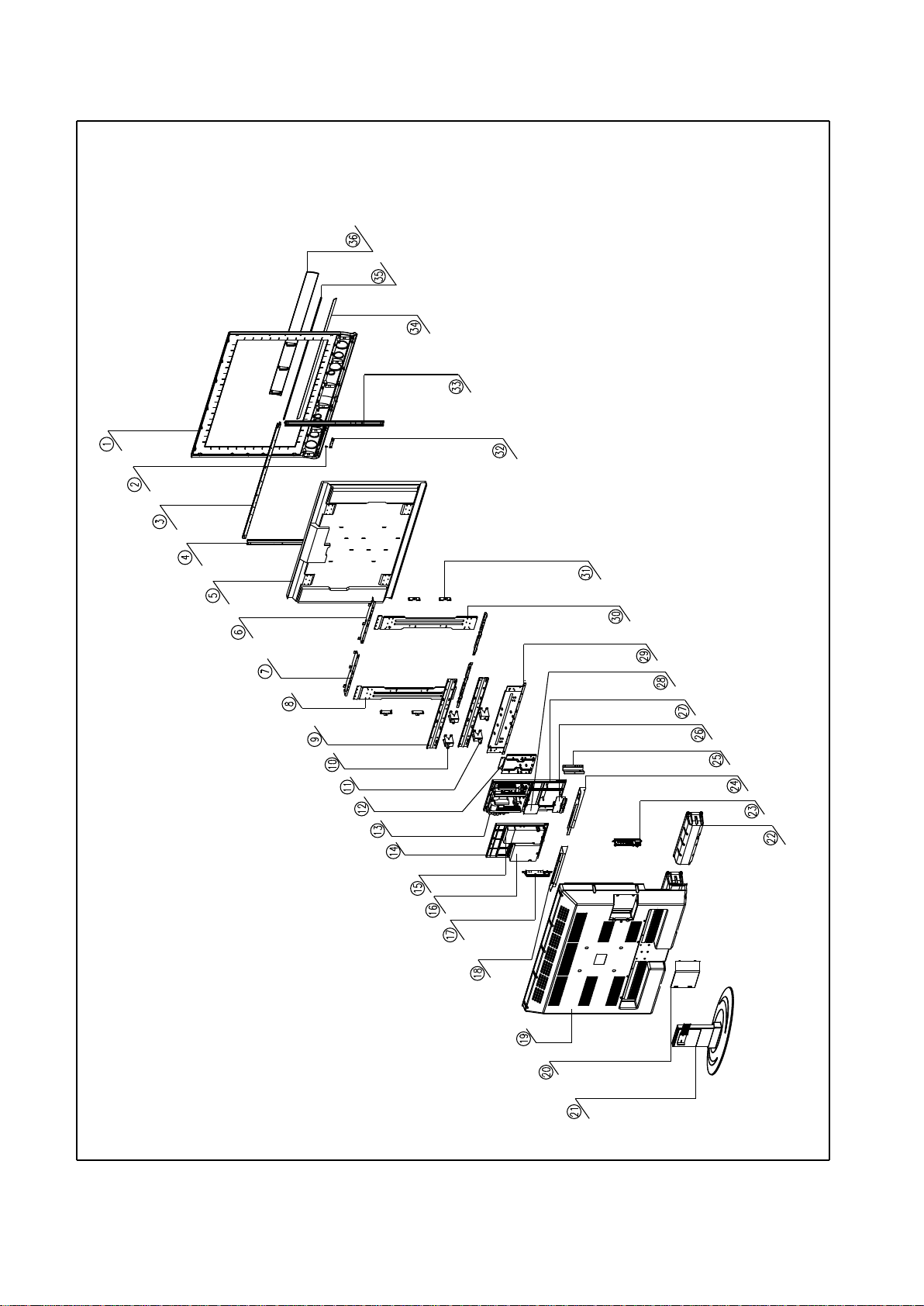
APPENDIX: Exploded view (LC-42X36)
Page 50
PART LIST OF EXPLODED VIEW
NO. DESCRIPTION
1 front cabinet
2 light conducting cloumn
3 fixed board (upper)
4 fixed board (left)
5 panel
6 front cabinet connection
7 front cabinet connection
8 panel connection
9 panel fixed bracket
10 wall mounting fixed bracket
11 wall mounting fixed bracket
12 stand connection
13 power board
14 main board frame
15 high frequency board
16 main board
17 key board
18 AV baffle (left)
19 back cabinet
20 back cover
21 stand
22 speaker
23 side AV conncetion board
24 AV baffle (right)
25 interface baffle
26 interface board
27 power board frame
28 USB board
29 panel fixed bracket
30 panel connection
31 panel connection
32 IR board
33 fixed board (right)
34 decorative bar
35 front cabinet decorative bar
36 speaker net
Note: design and specifications are subject to change without notice.
Page 51

APPENDIX-B: Exploded view (LC-47X36)
Page 52

PART LIST OF EXPLODED VIEW
NO. DESCRIPTION
1 decorative bar
2 speaker
3 decorative bar
4 front cabinet
5 front cabinet fixed bar (right)
6 front cabinet fixed bar (down)
7 side AV boarod
8 speaker
9 IR board
10 panel fixed bracket (right)
11 fixed bracket
12 power board bracket
13 panel fixed bracket (middle)
14 panel
15 panel fixed bracket (down)
16 column bracket
17 baffle
18 power board
19 terminal baffle
20 SCART connection board
21 video processing board
22 back cover
23 stand
24 back cabinet
25 main board
26 DVB-T digital board
27 wall mounting bracket
28 digital board bracket
29 panel fixed bracket (top)
30 panel fixed bracket (left)
31 panel connection bracket
32 key board
33 front cabinet fixed bar (lfet)
34 front cabinet fixed bar (top)
Note: design and specifications are subject to change without notice.
Page 53

9242HW3614
Ver.1.0
 Loading...