

Page 1

COLOR TELEVISION
LC30/40D9
Page 2

CONTENT
Safety instructions………………………………………………………………………..…
Instructions on adjusting and testing…………………………….…….…………………
Trouble shooting……………………………………………………….……………………
Method of software upgrading………………………………………….…………………
Briefing on LC30/40D9 and its working principle……………………………………..…
IC BLOCK DIAGRAM……………………………………………………………..……….
Wiring diagram……………………………………………………………..……………....
Serial NO. of parts……………………………………………………………………….…
Identification criteria for the bright spot and dark spot of the LCD screen………..…
Troubleshooting guide………………………………………………………………..……
Exploded views…………………………………………………………………………..…
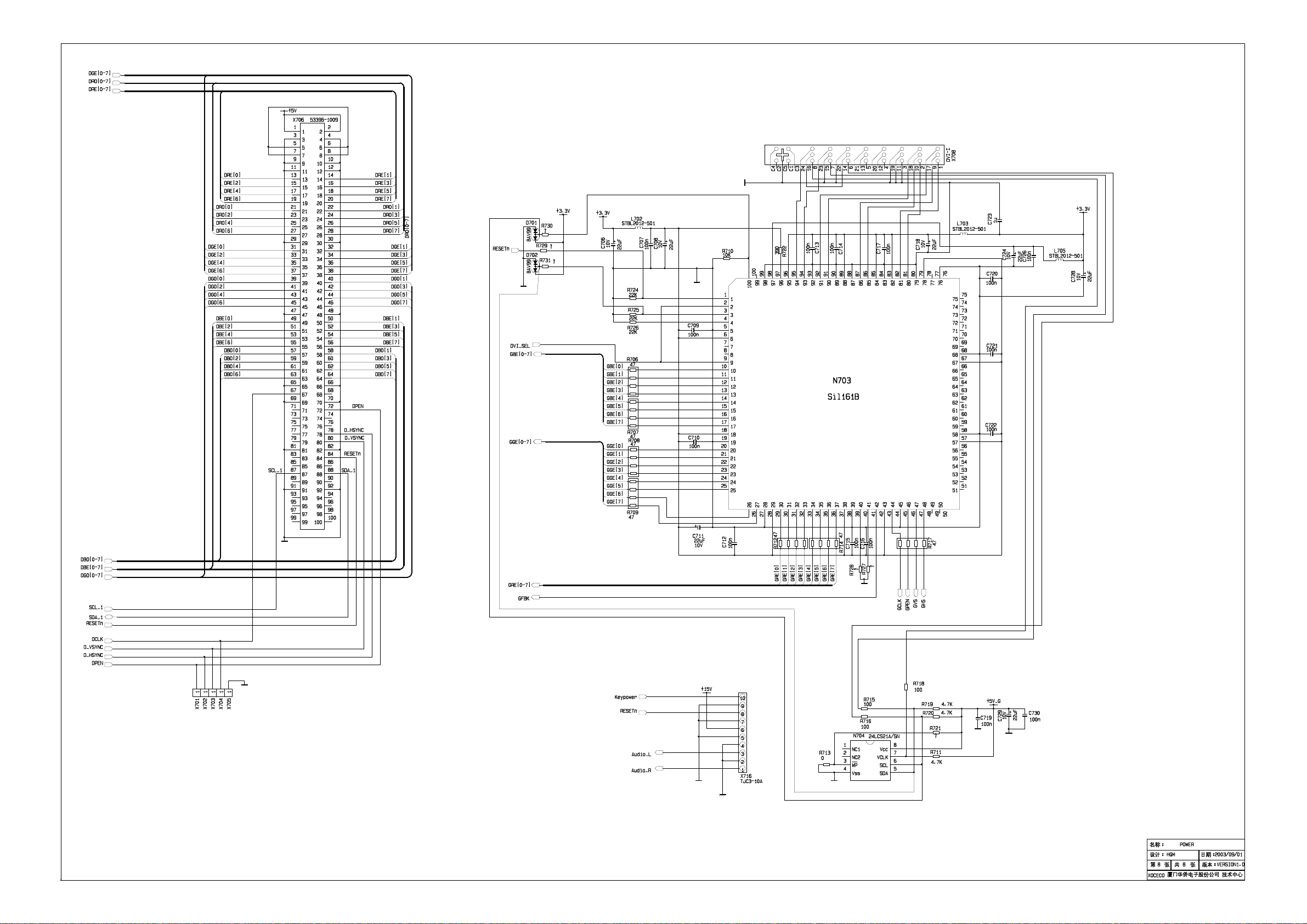
Schematic diagram…………………………………………………………………….…..
1
2
6
8
10
12
22
23
23
24
27
32
Page 3

Attention: This service manual is only for service personnel to take reference with. Before servicing
please read the following points carefully.
Safety instructions
1 Instructions
1.1 Be sure to switch off the power supply before replacing or welding any components or
inserting/plugging in connection wire
1.2 Anti static measures to be taken (throughout the entire production process!):
1.2.1 Do not touch here and there by hand at will;
1.2.2 Be sure to use anti static electric iron;
1.2.3 It’s a must for the welder to wear anti static gloves.
1.3 Please refer to the detailed list bef ore replacing components that have special safety requirements.
Do not change the specs and type at will.
2 Points for attention in servicing of LCD
2.1 Screens are different from one model to another and therefore not interchangeable. Be sure to use
the screen of the original model for replacement.
2.2 The operation voltage of LCD screen is 700-825V. Be sure to take proper measures in protecting
yourself and the machine when testing the system in the course of normal operation or right after
the power is switched off. Please do not touch the circuit or the metal part of the module that is in
operation mode.
Relevant operation is possible only one minute after the power is switched off.
2.3 Do not use any adapter that is not ident ical with the TV set. Otherwise it will cause fire or damage to
the set.
2.4 Never operate the set or do any inst allat ion wor k in bad env iron ment such as w et bat hroom, la undry ,
kitchen,or nearby fire source, heati ng equ ipme nt an d device s or ex posur e to s unlight etc. O therwi se
bad effect will result.
2.5 If any foreign substance such as water, liquid, metal slices or ot her matters happens to fall into the
module, be sure to cut the power off immediately and do not move anything on the module lest it
should cause fire or electric shock due to contact with the high voltage or short circuit.
2.6 Should there be smoke, abnor mal smell or sound fro m the module, pleas e shut t he power of f at once.
Likewise, if the screen is not working after the power is on or in the course of operation, the power
must be cut off immediately and no more operation is allowed under the same condition.
2.7 Do not pull out or plug in the connection wire when the module is in operation or just after the power
is off because in this case relatively high voltage still remains in the capacitor of the driving
circuit.Please wait at least one minute befor e t he pulling out or plugging in the connection wire.
2.8 When operating or installing LCD please don’t subject the LCD components to bending, twisting or
extrusion, collision lest mishap should result.
2.9 As most of the circuitry in LCD T V set is comp osed of CMOS i ntegrate d circuits, it’s neces sary to pay
attention to anti statics. Before servicing LCD TV make sure to take anti static measure and ensure
full grounding for all the parts that have to be grounded.
1
Page 4
2.10 There are lots of connection wires between parts behind the LCD screen. When servicing or
moving the set please take care not to touch or scratch them. Once they are dam aged the screen
would be unable to work and no way to get it repaired.
2.11 Special care must be taken in transporting or handling it. Exquisite shock vibration may lead to
breakage of screen glass or damage to driving circuit.
Therefore it must be packed in a strong case before the transportation or handling.
2.12 For the storage make sure to put it in a place where the environment can be controlled so as to
prevent the temperature and humidity from exceeding the limits as specified in the manual. For
prolonged storage, it is ne cessary to hou se it in a n ant i-moist ure bag an d put t he m altoget her in one
place. The ambient conditions are tabulated as follows:
Scope for operation
0----+50 C
Temperature
Scope for storage
humidity Scope for operation
Scope for storage
2.13 Display of a fixed picture for a long time may result in appearance of picture residue on the screen,
as commmonly called “ghost shadow”. The extent of the residual picture varies with the maker of
LCD screen. This phenonm enon doesn’t represent failure. This “ghost shadow” may remain in the
picture for a period of time (several minutes).But when operating it please avoid displaying still
picture in high brightness for a long time.
-20----+60 C
20%---85%
10%---90%
3. Points for attention during installation
3.1 The front panel of LCD screen is of glass. Wheng installing it please make sure to put it in place.
3.2 For service or instatallation it’s necessary to use specified screw lest it should damage the screen.
3.3 Be sure to take anti dust measures. Any foreign substance that happens to fall down between the
screen and the glass will affect the receiving and v iew ing effect
3.4 When dismantling or mounting the protective partition plate that is used for anti vibration and
insulation please take care to keep it in intactness so as to avoid hidden trouble.
3.5 Be sure to protect the cabinet from damage or scratch during service, dismantling or mounting.
Instructions on adjusting and testing
The adjustment of LC22K9 excludes 2.30
2.1 Adjusting and calibrating the equipment
PM 5518(video frequency signal generator), K-7253(VGA signal generator),CA210(white balancer)
2.2 Adjustment and calibration procedure
2.3 Adjusting and calibrating the monitor board
Place the monitor board o n the test ing j ig, turn o n th e pow er supp ly and swit ch on the set to s ee if it
2
Page 5

is normal.
2.3.1 Adjusting the white balance of monitor board
Push the “Rest” key and “OK” key under the cover of the remote control set, repeat the push, enter
the factory menu. Select factory reset to initialize the MONITO R
Input the DVI signal to mo nitor boar d. (K-725 3 ti me339 p attern 63 0 8 gray degree sig na ls, input the
DVI signal to socket with 26 cores of monitor board by way of patc h panel). Adjust the intermediate
second and seventh gray degree with CA210 white balancer. Preset value of R,G,B CUT to
100,and R,G,B DRV to 150, then, adjust the second gray degree (bright ness: about 9nit) by R,G,B
CUT, to set the color coordinates of second gray degree to 270, 283. Adjust R,G,B DRV to set the
color coordinate of seventh gray degree to 270 and 283.
Note: Because the values of R,G,B CUT and R,G,B DRV directly determines the values of
brightness and contrast at the DVI terminal of monitor board, the white balance should be
adjusted according to the preset value strictly. The value after adjusting should be within
+/-10 of the preset value.
2.3.2 Calibrating ADC of Monitor
After finishing the adj ust ment of 2.3. 1, set t he VG A signal to 1024X768 60Hz mode. Access the
pane signal and connect it to VGA terminal of monitor. Adjust h port of the picture to make the
picture fully occupy the screen. Enter the factory menu and select items for ADC calibration and
calibrate the ADC according to the indication on the screen.
2.3.3 Adjusting the white balance of monitor:
Input 8 gray degree signals of 1024X768 60Hz mode, push “display” key on the rem ote control
set, adjust brightness and contrast, to set the brightness of second gray degree to 5nit and seventh
as 400nit.
For the diagram of adjustment and calibration procedure, see diagram 1
3
Page 6
V
t
k
f
f
B CUT and B DRV is fixed as 128. Adjust R G CUT,to make second degree of the color
coordinate as 270 283. Adjust R G DRV to set seventh degree of the color coordinate to 270
283. Adjust R G CUT and R G DRV again and again, until both of the two gray degrees are at
270 and 283.
2.4 Connect decoder board and push button board with the monitor board verified to be normal
(LC-30K9/LC40K9 power is as per connection diagram 203-L30K90-01JL whereas LC-22K9 is as
per 203-L22K90-01JL). Af t er pow er on, observe if the display is normal.
Method to enter factory menu: Continuously push key of “VOL+” “Mute”, “V ideo” to enter factory menu.
When the first line of each and every adjusting item is in t he highest brightness push “ENTER” key
to select different adjustment items. When VGA and DVI are input, select “mode” and then push
Production of the main board and decoders on the line
General assembly and combined calibration
Connect central signal source, check T
functions (station skipping, analog
quantity control etc) . Check if the outpu
of speaker is normal
Input AV/S and HDTV signal and chec
following functions of the terminals
Input VGA signal (one format), check i
display is normal under the PC status,
and functions (analog control), central o
line and field etc.
Check accessories, then packing
Figure 1. Adjustment and calibration procedure
Check if FLASH is written
Check Monitor board
Check decoders in media board
4
Page 7

“ENTER” key and select three color temperatures 6500K,9300K,12000K. Push “MENU” to quit
factory menu.
Notice: Adjustment of Media Box must be performed under the mode --”Nature” of picture.
2.5. White balance adjustment for Media Box TV channel
Continuously press keys of “multi-picture”,”<”,”>”,”Confirm” to
Enter the factory menu. Select “Calibration” “white balance adjustment”
under the submenu. Connect AV signal(K-7253 TIME381 PATTERN 630 8 degree of
gray signal). Use the white balancer to adjust both 2
the brightness and contrast so that the 2
th
the 7
order of brightness 350 nit. Set B CUT and B DRV fixed as 128. Adjust
R,G CUT so that the 2
so that the 7
th
order of color coordinates are 270 283. Repeat this adjustment
nd
order of color coordinates are 270 283. Adjust R, G DRV
nd
order of brightness is 5 nit and
nd
and 7th orders. Adjust
for R,GCUT and R,G DRV unt il t he t wo levels of gray degree are both set to 270,
283.
2.6. White balance adjustment for VGA port of Media Box
Switch VGA signal to the mode of 1024x768 60 Hz. Access the 8 degrees of gray
signal and connect to the VGA port of Media Box. Continuously press keys of
“multi-picture”,”<”,”>”,”Confirm” to enter the factory menu. Select
“Calibration” “white balance adjustment” under the submenu. Use the white
balancer to adjust both 2
so that the 2
nd
order of brightness is 5 nit and the 7th order of brightness 400
nit. Set B CUT and B DRV fixed as 128. Adjust R,G CUT so that the 2
nd
and 7th orders. Adjust the brightness and contrast
nd
order of
color coordinates are 270 283. Set B DRV as fixed. Adjust R,G DRV so that the
th
7
order of color coordinates are 270 283. Repeat this adjustment for R,GCUT
and R,G DRV until the two levels of gray degree are both set to 270,283.
2.7.White balance adjustment for HDTV port of Media Box
After adjustment in 2.4.1 is over, connect HDTV signal to HDTV port of Media Box for adjusting the
white balance of HDTV port. Input the 8 degrees of gray signal in the mode of 1280 x 720 60
Hz(720p). Adjust the brightness and contrast so that Adjust the brightness and contrast so that the
nd
2
order of brightness is 5 nit and the 7th order of brightness 400 nit. Continuously press keys
of”multi-picture”,”<“,”>“,”Confirm” to enter the factory menu. Select “Calibration” “YpbPr white
balance adjustment” under the submenu. Adjust R,G CUT and R,B GRV so that both the 2
nd
and 7th
orders of gray color are 270 283.
Input 8 degrees of gray signal in the modes of 640x480 60 Hz(480 p)and 1920x540 60 Hz(1080
i)separately. Repeat the adjustment as above until the 2
nd
and 7th orders of gray are both 270 283.
3. Functional inspection
3.1 TV function
Enter search menu---auto search, connect ce ntral signal to RF terminal and ch eck if there is missing
of station.
Input A21 signal and check the function of CCD.
3.2 AV/S HDTV terminal
5
Page 8
Input HDTV signal to AV/S, and check if it is normal.
3.3 VGA connector
Insert VGA signal connector, input 640 x 480@60 Hz VGA format signal, and check if display is
normal. If there is interfere on the picture, push the auto-adjust key on the remote control set once
more, check if the display is normal.
Trouble shooting
Before servicing please check to find the possib le causes o f the troubles acco rding to t he t able below.
1.Antenna:
Picture is out of focus or jumping Bad status in signal receiving
Maybe broadcast signal itself is not good
Check if the outdoor antenna is disconnected.
Check if the antenna is correctly oriented.
Fringe in picture Check if the antenna is correctly oriented.
Maybe there is electric wav e reflect ed from hillt op or building.
Picture is interfered by stripe
shaped bright spots
There appear streaks or light color
on the screen
Possibly due to interference from automobile, train, high
voltage transmission line, neon lamp etc.
Maybe there is interference between antenna and power
supply line. Please try to separate them in a longer distance.
Check if interfered by other equipment and if interfered
possibly by the equipment like transmitting antenna, non
professional radio station and cellular phone.
6
Page 9
2.TV set:
Symptoms Possible cause
Unable to switch the power on Check to see if the power plug has been inserted properly into
the socket.
No picture and sound Check to see if the power s upp l y of liq uid c rystal TV has been
switched on. (as ca n be indic ated by th e red LED at the front
of the TV set)
See if it’s receiving the signal th at is transmitted from other
source than the station
Check if it’s connected to the wrong terminal or if the input
mode is correct.
Check if the signal cable co nnecti on b et we en vid eo f r equency
source and the liquid crystal TV set is correct.
Deterioration of color phas e or col or
tone
Screen position or size is not proper Check is the screen position and size is correctly set up.
Picture is twisted and deformed Check to see if the picture-frame ratio is properly set up.
Picture color changed or colorless Check the “Component” or ” R GB” setti ngs of th e liqui d c r ystal
Picture too bright and there is
distortion in the brightest area
Picture is whitish or too bri ght in the
darkest area of the picture
No picture or signa l produced from
the displayer if “XXX in
search”appears.
There appears an indication “outside the receivable scope)
Remote control cannot work
properly
No picture and sound, but only
hash.
Check if all the picture setups have been corrected.
TV set and m ake proper adjus tm ent according to the signal
types.
Check if the contrast setting is too high.
Possibly the output quality of DVD broadcaster is set too high.
It maybe also due to improper terminal connection of the video
frequency signal in a certain position of the system.
Check if the setting for the brightness is too high
Possibly the brightness grade of DVD player(broadcaster)is
set too high.
Check if the cable is disconnected.
Check if it’s connected to the pr oper terminal or if the input
mode is correct.
Check if the TV set can recei ve input sign al. The si gnal is no t
correctly identified and VGA format is beyond the specified
scope.
Check if the batteries are installed in the reverse order.
Check if the battery is effective.
Check the distance or angle from the monitor.
Check if there is any obstruct bet ween the rem ote contr ol and
the TV set.
Check if the remote control signal- receiving window is
exposed to strong fluorescence.
Check if the antenna cable is c orrectly connected, or if it has
received the video signal correctly.
7
Page 10
Blur picture Check if the antenna cable is correctly connected.
Of if it has received the right video signal.
No sound Check if the “mute” audio frequency setting is selected.
Check if the sound volume is set to minimum.
Make sure the earphone is not connected.
Check if the cable connection is loose.
When playing VHS picture search
tape, there are lines at the top or
bottom of the picture.
When being played or in pause VHS picture search tape
sometimes can’t provide stable picture, which may lead to
incorrect display of the liquid crystal TVIn this case please
press “auto” key on the remote control so as to enable the
liquid crystal TV set to recheck the signal and then to
display correct picture signal
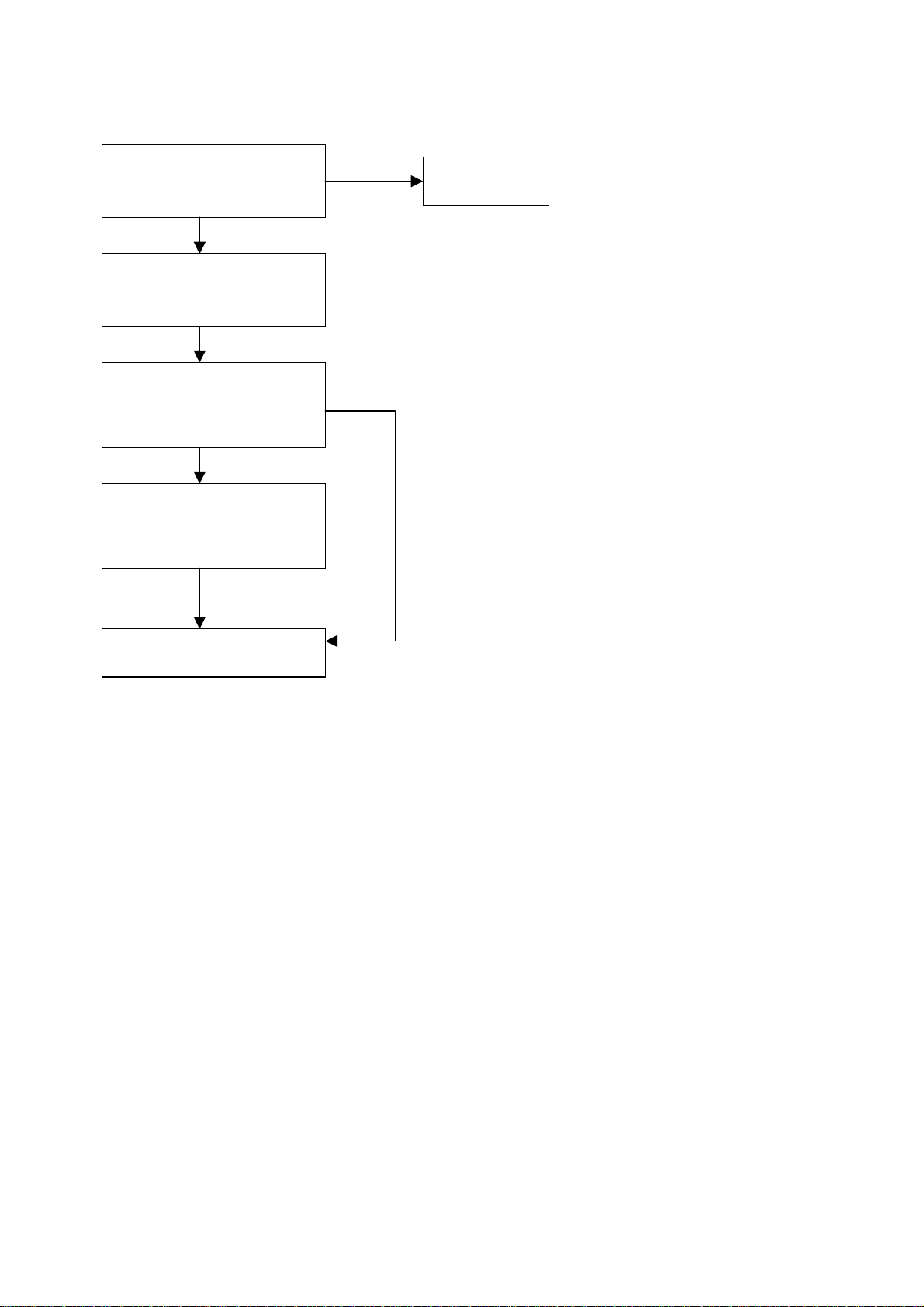
Method of softwar e upgrading
Steps of soft w are upgrading are as follow s:
1. Select a serial connection wire and a VGA connection wire and then connect them by means of a
patch panel;
2. Use a serial wire to connect the PC to the patch panel and set TV set to off state;
1. Open the software upgrade file holder and double click
FlashUpgraderNT(use under window 2000/XP/NT)
FlashUpgrader(use under window 98),
The following interfaces will show up after running the pr ogr am:
8
Page 11
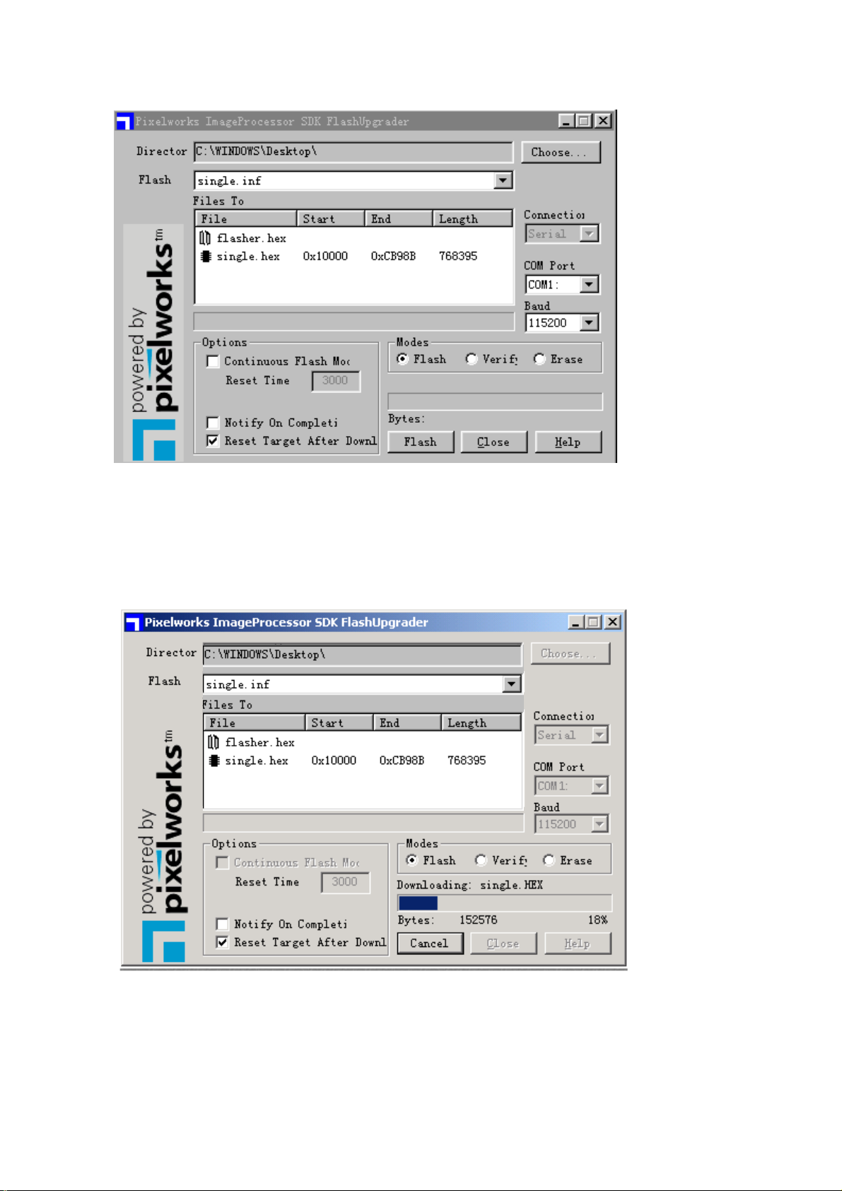
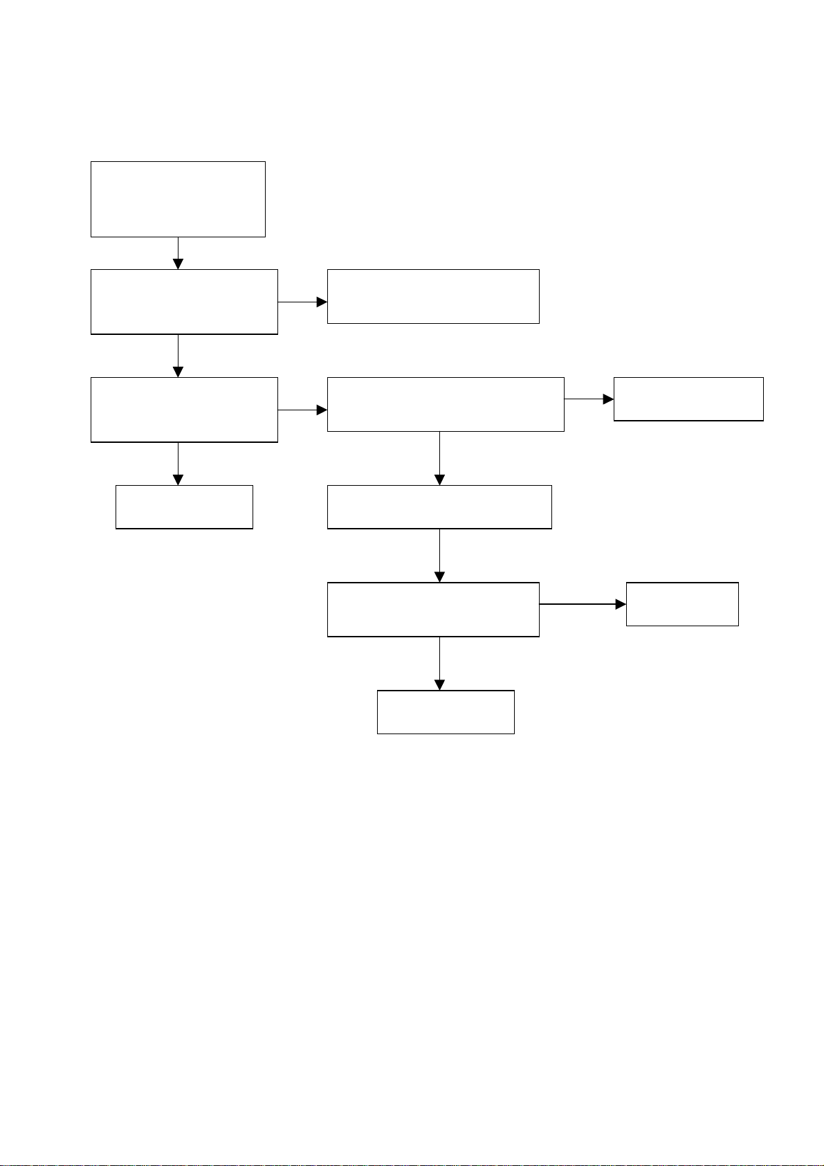
Based on the computer features, set up the serial port(COM Port). Select corresponding serial port
(if it’s unable to FLAS H WRITE, change t o another port) . Baud is se lected to be 115200. Then select
Reset Target After Download. Click FLASH pushbutton, it’s ready to run. For other settings, please
refer to the Fig. Above (already defaulted by the system, normally no need t o change).
4. Switch on TV set the FLASH wr it e program begins t o run;
5. After FLASH write is over , push but ton “cancel” will beco me flash. Then shut the main power supply
and it’s OK just switch it on again.
Note: Do not shut the power off or turn the TV set on during the FLASH write. Otherwise it may
lead to no way for flash to rewrite.
9
Page 12

Briefing on LC30/40D9 and its working principle
LC30/40D9 is a multi-media liquid crystal TV broadcast receiver covering all systems. 40/30” liquid
crystal display screen is used as its display device. It has all-system color receiving capability. It is also
provided with AV input, S-VHS input, high definition signal port of component Y Pr/Cr Pb/Cb, digital port
of DVI, PC VGA input port, AV output port, and earphone output port. Thanks to the two RF input ports
provided this TV set can realize browsing function of PIP,POP and multi-pictures both between video
signals and between video signal and AV,VGA,DVI signals. It is also equipped with a PCMCIA card
reader module, which can be connected with m emory cards like CF,SD and SM, therefore capable of
playing the photos taken by digit al camera.
This TV set is also provided wit h a PCMCIA card reader module and can connect memory cards li ke
CF, SD, SM for playing the photos taken by digital camera. This machine adopts the form of set-top-box
plus MONITOR. If the set-top-box is removed it is a standard computer displayer. If equipped with the
set-top-box it becomes a pow erful T V receiv er. So it’s a flexible ty pe of structu re. The pow er supply is a n
externally instal le d power adapter. The software prov ided ca n per for m the con trol ov er t he power su pply.
Therefore the power consumption when in standby can be lower than 1 W. It’s really a kind of
environmental protection energy saving “green” power supply, and up to the international advanced
level.
LC40D9/30D9 liquid crystal TV driving board is mainly composed of three plates which are
respectively video processing plate, digital processing plate and monitor plate. On the video processing
plate, RF signal goes through two integrated tuners and produces two routes of color all-TV signals,
which are connected together w it h t w o ways of AV signal by way of plug socket and then sent to 3230IC
on the digital processing plate for treatment. On this plate, TV,AV and the various ways of audio signals
VGA, DVI, YpbPr, YcbCr sent from the plug socket are subject to treatment in MSP3440IC. The
processed audio signals are then sent to Monitor plate for amplification treatment.
The digital processing plate in mainly intended to process various signals of TV and AV as well as
VGA, DVI, YpbPr, YcbCr on this plate itself.
DVI after processing in SII161IC and VGA, YpbPr, YcbCr after processing in AD9883 as well as TV, AV
signals(TTL signal)after processing in Gport 3230 are sent at the same time to PW181 for Sclar
treatment. The TV, AV signals that have been processed in Vport 3230 are sent to PW181 for treatment
only after deinterlacing treatment in PW1230. The signal processed in PW 181 is subject to conversion
into DVI signal in IC SII170 before being output to Monitor plate for treatment.
Monitor plate functions mainly to process DVI signal from the digital processing plate and the VGA
signal from this plate itself. Furthermore, IC LX1722 also perform power amplification treatment for the
audio signal that has been processed in the video processing plate.
10
Page 13
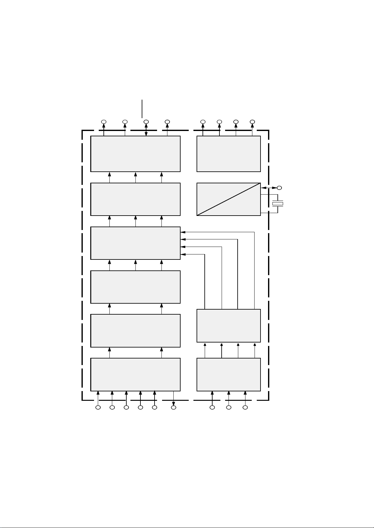
LCD TV System Block Diagram
Media Box
VGA
Y Cr Cb
AV IN
S-Video
TV1 V-CHIP
RF
RF TV2
SDA SCL
RXD/TXD
power
RS232
L/R
CABLE
MONITOR
DVI monitor Lamp/
power panel
PCMCIA
Module
3D Filter
uPD64083
TUNER1
TUNER2
SDA555
Mcu
MSP3420
AUDIO
PROCESSOR
M62429
LX1722
Amplifier
Switch
AD9883
ADC
VPC3230
Decoder
VPC3230
Decoder
Z86229
V-CHIP
M62494
SRS
VGA
SDRAM
PW1230
Deinterlace
II C BUS
Image Processor
Scaler
PW131
Mcu
OSD
PW181
Image Processor
Scaler
Mcu
PIP
OSD
FLASH
29LV800TTC
MAX232
CONNECTOR
CONNECTOR
DS90C383
LVDS
DRIVER
SiI170
DVI
Box
power
DC IN
Connector
PANEL
SPEAKER
Page 14
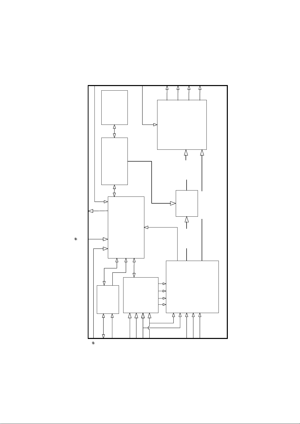
IC BLOCK DIAGRAM
(1).PW181
IR
IR R C VR (1:0)
RxD, TxD
NM I E X TINT
Interrupt
UART
DVS,
DHS,
DEN,
RGBE
(23:0)
RGBO
(23:0)
Decoders
Memory
OSD/ C PU
Contro er
SDR AM
OSD and C PU
Contro e r
Display Port
Bus
OSD
Mem o ry
Expander
Color Matri x,
Gamma Correction
CLTs, Color Space
OSD
B end
Contro &
DCLK
T m ng
D sp ay
Gener ator
Internal Block Diagram
*For internal cloc k genera torDCLKEXT,
A(19:0),
CPUTM S,
BHEN,
D(15:0),
RA M OE,
RAMWE,
CPUTCK,
CS(1:0),
ROMWE,
PortA
CPUT DI
CPUTDO
RD, WR
ROMOE
(7:0)
Sca er
Imag e
C ock
MCLK DCLK UCLK
Dua PLL
Generator
Watchdog
and T mer s
Memory Out Bus
XO*
XI*
M CLKEX T ,
u
16-b t
T urbo P
Interface
ROM/RAM
Pro cesso r
M cro p r o cesso r B u s
Ser a
2-W re
Memory
Interface
Processor
Image
Sca er
Hor zonta
Frame
Buffer
SDRAM
CRISP
Image
Sca er
Fram e
Buffer
Memory
Contro er
Reset
Bus
Memo ry In
V deo
De nter ac e
No se
Spat a
Reduc t on
Master Reset
(7:0)
PortB
(7:0)
PortC
Por tD(7:0)
GPIO PWM
Por tE(7:0)
Por tF(7:0)
VRGB
Video Port
(23:0)
Color S p ace
Sync Decoder
Converter HDCP
Auto Image Optimizer
FIELD
VVS, VHS,
VCL K , VPEN ,
GCLK, GFBK ,
Graphics Port
GHS, GSOG
GPEN, GVS,
Sync Decoder
GRGB
Color Spa ce
Auto Image Optimizer
(47:0)
Conver ter HDCP
GREF,
GCOAST,
GHSF OUT
GBLKSPL,
12
Page 15
(2).VPC3230
Y OUT
Output
2D Scaler
Y
Mixer
Y
Color
Formatter
PIP
Decoder
CrCb
OUT
ITU-R 656
ITU-R 601
Mode
Panorama
Cr
Cr
PA L
NTSC
YCOE
Memory
Contrast
Brightness
Cb
Cb
SECAM
FIFO
Control
Peaking
Saturation
CNTL
LL Clock
H Sync
V Sync
AVO
+
Sync
Clock
Generation
C Bus20.25 MHz
2
I
C Bus
2
I
Clock
Gen.
Tint
Y
Cr
Cb
Adaptive
Analog
CIN
Filter
Comb
Front-end
VIN1
PA L
NTSC
AGC
2 ADC
Y/G
Processing
Analog
Matrix
U/B
Component
Contrast
V/R
Front-End
Saturation
Tint
Brightness
FB FB
4 x ADC
FB
VIN2
VIN3
VIN4
VOUT
3
1
RGB/
YCrCb
RGB/
YCrCb
Page 16

(3).MSP3450G
Loud-
speaker
Subwoofer
Headphone
2
IS
SCART1
SCART2
Loud-
DAC
speaker
Pre-
De-
DAC
Sound
Processing
processing
Sound
Processing
Headphone
Prescale
DAC
Source Select
Select
Output
SCART
DAC
Prescale
ADC
modulator
DSP
Input
SCART1
SCART
SCART2
ADC
2
I S12I S2
Sound IF2
Sound IF1
SCART3
Select
SCART4
MONO
14
Page 17

(4).UPD64083
EXTDYCO9-EXTDYCO0
DYCO
DCYO9-DCYO0
EXTALTF
select
AYO
ALTF
10-bit
Y-high freq.
YCNR
Y- D A C
coring
4fSC
Y-high freq.
KIL
YCNR
peaking
YNR
Recursive
YCNR
MNNR
ACO
CBPC
10-bit
Y- D A C
Adjustment
C-BPF & delay
SDA
SCL
SLA0
RSTB
CKMD
CLK8
FSCI
FSCOXOXI
BPF
8fSC
8fSC
encoder
PLL
4fSC
C bus
2
I
interface
ID-1
aperture
Y-Vertical
compensation
10-bit
SC -DAC
f
fSC
generator
CNR
Recursive
Error
detection
VCLY
10-bit
Y-ADC
Clamp
AYI
VRTY
Delay
EXTADINS CBPY
VRBY
EXTDYCOS
10-bit
Bias
ACI
mixer
Chroma
C3
filter
Line comb
HH
C-ADC
YCNR
VRTC
VRBC
Motion
detection
filter
Line comb
delay
flame
4-Mbit
filter
Line comb
HH
memory
H
YCNR
MNNR
WCV-ID
decoder
ID-1
decoder
Non-
standard
HV
counter
signal
detection
Sync
separation
CSI
15
Page 18
(5).SiI-170
MSEN
HTPLG
HDCP
Keys
EEPROM
HDCP
Encryption
Engine
EXT-SWING
TXC+/-
TX0+/-
TX1+/-
TX2+/-
PaneILink
TMDS tm
Digital
Core
encrypted
data
XOR
Mask
control signals
PD
IIC
SDAS
ISEL/RST
Register
-----------------
Configuration
Logic Block
Slave
SCLS
DE
VSYNC
HSYNC
Gen
IDCK-
IDCK+
clear data
Data
Capture
Logic
DE
D[23:0]
Block
CTL3
16
Page 19

(6).SiI-161
DATA
24
QE[23:0]
24
CTL3
ODCK
QO[23:0]
CTL2
DE
Panel
DATA
CTL3
CTL2
CTL1
SCDT
VSYNC
HSYNC
face
Inter-
Logic
CTL1
DATA
VSYNC
HSYNC
Decoder
SYNC2
SYNC2
CH2
Dat a R eco very
Control
Termination
VCR
Channel
Dat a R eco very
SYNC1
SYNC
SYNC1
VCR
SYNC0
SYNC0
CH1
CH0
Data Recovery
VCR
PLL
VCR
RX2+
PIXS
HS_DJTR
OCK_INV
EXT_RES
RX2-
RX1+
RX1-
7
1
RX0+
RX0-
RXC+
RXC-
PDO
STAG_OUT
ST
Page 20

(7).SAD555
XRAM
SRAM
16K x 8bit
V
H
character
ROM
16K x 8
BLANK/COR
FIFO
S
B
V
C
ADC
slicer
Acquisition
acquisition interface
C
D
A
4
X
Bus
Arbiter
Display logic
RAM/R OM Interf ace
CLUT
Regs
Display
B
G
R
ADC
Analog Mux
program ROM
128 x 8
WR
RD
PSEN
ALE
D[0 to 7]
A[0 to 15]
A[16 t o A20]
Memory
stack
128 x 8
Memory
Extension
Core
Interrupt
Extension Unit
Counter 0
Controller
Counter 1
RAM
256X8
ADC
interface
WDT
Capture control
Peripheral
Bus
interface
PWM
8
1
Port Logic
p[0 to 4]
clock &
sync
system
SFRs
UART
Page 21

(8).LX1722
25
VDD
27
LISN
CLOCK
28
RPWM
CPWM
10
SLEEP
1
24
24
26
4
VREF
V25
CN
PVDD
CP
PVDD
+
SYNC
5
OSC
CLK
220mV
UVLO
&
REFERENCE
5V
Referenc e
6
5V
CURRENT SENSE
Reference
LEAOUT
LEAIN
LAMPOUT
LIN
LIN+
LMUTE
14
13
11
23
LP+
FAULT
TIMER
9
8
7
ERROR AMP
INPUT AMP
MUTE
MUTE
MUX
CLK
SQ
RQ
2.5V
OUTPUT
DRIVERS
&
LOGIC
22
21
20
15
17
16
LN+
LN
LP
LFAOUT
LFBK
LFBK+
FEEDBACK AMP
2.5V
19
Page 22

(9).AD9883
R
AIN
G
AIN
B
AIN
HSYNC
COAST
CLAMP
FILT
CLAMP
CLAMP
CLAMP
SYNC
PROCESSING
AND CLOCK
GENERATION
A/D
A/D
A/D
8
R
OUTA
8
G
OUTA
8
B
OUTA
MIDSCV
DTACK
HSOUT
VSOUT
SOGOUT
SCL
SDA
A
REF
REF
BYPASS
SERIAL REGISTER
AND
0
POWER MANAGEMENT
20
AD9883A
Page 23

(10).PW123
Unit
Display
Deinterlacing
Video
Enhance
Up-Scaling
DGRGB[23:0]
DEN
Digital
(dual pixel)
DHS
DVS
DCLK
DENR
DENG
DENB
Timing
Display
Display Port
COMP
RSET
VREFOUT
VREFIN
ADB
Analog
Port
Display
ADG
ADR
CGMS
MWE
MCAS
MRAS
MCLKFB
MCLK
MD[15:0]
MA[13:0]
Interlaced
YUV
I-Channel
V601
and
Memory
Controller
YUV /
Input
Video
V656
XTALO
DCLKMCLK
PLL and
Line Buffer
Down-
B-Channel
RGB
Scaling
Unit
Input
Memory Unit
Oscillator
Programming Unit
Sync
Decoder
TDI
TCK
TDO
PVVS
PVHS
Component
PVCLK
CREF
SVVS
SVHS
SVCLK
DGVS
DGHS
DGCLK
RESETn
TMS
TRSTn
XTALI
MCURDY
MCUCMD
MCUWR
MCUCS
MCUA[7:0]
MCUD[7:0]
2WA2
2WA1
SDA
SCL
21
Page 24

WIRING DIAGRAM
Page 25

Serial No. of Parts
203
667
Remote sensor 301-UL40D9-21RA 301WL40D9-04 301-UL40D9-21RA
adapter 302-AD12C-03 302-AD12C-03 302-AD13D-02
LCD PANEL 335-40002-00 335-30002-00 335-29002-00
Media box 615-10363-00 615-10364-00 615-10394-00
Video processing 667-L40D9-40 667-L40D9-40 667-L40D9-40
Data processing 667-L40D9-69 667-L40D9-69 667-L40D9-69
MONITOR 667-L40D9-25A 667-L32D9-25 667-L30D9-25
PCMCIA 667-L40D9-90 667-L40D9-90 667-L40D9-90
203-L40D90-10
203-L30D90-11
203-L30D90-12
Identification criteria for the bright spot and dark spot of the LCD screen
Category criteria
One single
Bright
t
spo
Dark
spots
Total defected point ≤8 ≤7 ≤5 ≤4 /
Notes:
1. Definition of defected point (bright spot, dark spot): It is identified as a defected point if its
2. Definition of bright spot: It is identified as a bright spot if it is bright in the state of dark field
3. Definition of dark spot: It is identified as a dark spot if it is dark in the state of white field and
spot
2 neighboring
spots
Total No. ≤5 ≤2 ≤5 ≤2 ≤3
One single
spot
Two
neighboring
spots
Total No. ≤6 ≤7 ≤5 ≤4 ≤10
area exceeds 1/2 of a single picture element (R,G,B).
and its bright size remains unchanged
its dark size remains unchanged
15" 20" 22" 30" 40" 15" 20" 22" 30" 40"
≤5 ≤2 ≤5 ≤2 ≤3
≤2 ≤1 ≤2 ≤1 ≤1
≤6 ≤7 ≤5 ≤4 ≤10
≤2 ≤2 ≤2 ≤1 ≤5
4. Definition of two neighboring points: Defects of a group of picture elements(RB,RG,GB).
Q’ty allowed Distance between two spot s
≥15mm
≥15mm
≥10mm
≥5mm
23
Page 26

TROUBLESHOOTING GUIDE
t
(press remote control or BOX power button,then the red indication lamp power off,in normal condition
the lamp change from red to blue.)
NO SCREEN DISPLAY,BACK LIG HT ON
Back light off
no
Check whether power
supply IC
normal
Check whether N205 pin3 the
voltage changing low level
No screen display,back
light off
Check wether back ligh
power +14V is normal
normal
Check whether N407 pin 7 the
voltage +5V output
Flash write process in N407
no
no
no
Obviate back light
power supply is normal
Check power supply
Replace N205
circuit and IC
24
Page 27
NO SOUND
Check whether N401 pin2
Check wether N404 pin2
have triangle-waveform
Check wether the front of
no
L404 L405 L406 L407
output waveform (scale1:1)
is normal
pin7 output
output
yes
no
Replace N404
no Check whether audio input
Replace N401
25
Page 28
DIGITAL BOARD TROUBLESHOOTING GUIDE
r
r
DISPLY “BOX SEARCHNG”
Test N602 waveform
from TXC± TX0± ~
TX2±
Test whether N602 powe
supply +3.3V
Test wether N302 pin2
pin4 pin5 pin57 waveform
Replace N602
no
yes
yes
no
no
Check path turned 5V into
3.3v
Test whether PW181 powe
supply 1.5v; 2.5v; 3. 5v
Test oscillator G501 waveform
Check N503 rest pin5 and
pin6
Replace G501
no
Check LDO circuit
yes
yes
abnormalit
Replace N03
normal
26
Page 29

NO PICTURE
y
x
R
r
R
r
Display “bo
searching”
Replace digital
board
yes
Check whether displa
LOGO in power on
Display “TV searching”
Check wether digital
board X2 pin 1 input
Replace VIDEO processing
board
Check MONITO
board power supply
yes
Replace MONITO
board
no
no no
Check whethe
monitor board X402
connecting well
Replace powe
adapter
MONITOR BOARD
MONITOR works normally,but can’t test box, it maybe cause by the follow ing problem.
MONITOR
normal
no
Check wether X103 pin3
pin12 the voltage 15V
Still can’t test box
yes
Test N301
pin7,8 ,10,11,12,14,
16,17 have signal
normal
Replace N301
Obviateing fault
Connecting
box,check X103
pin21 connects GND
Still can’t t e st box
no
OK
Obviateing
fault
OK
yes
27
Page 30

30
LC30D9 EXPLODED VIEWS
31
40
39
38
37
36
35
34
33
32
1
25
24
23
22
21
20
19
26
27
28
29
2
3
4
5
6
7
8
9
10
11
12
13
14
15
18
16
17
Page 31

Exploded views list(LC30D9)
NO. Name NO. Name
21 stand base cover(righ)
20 stand base
19 stand base cover(left) 40 front cover board
18 stand base board 39 IR receiver
17 terminal panel 38 remote sensor board
16 signal cable supporter 37 speaker socket connector
15 connector cover(left) 36 socket wp4-4
14 connector piece(left) 35 column supporter
13 speaker's back cover(left) 34 speaker grille(right)
12 loudhailer(left) 33 speaker's front cover(right)
11 socket wp2-9c(left) 32 loudhailer(right)
10 speaker's front cover(left) 31 socket wp2-9c(right)
9 shielding board 30 speaker's front cover(right)
8 shielding board 29
screw
7 speaker grille(left) 28 connector piece(right)
6 shielding cover 27 connector cover(right)
5 MONITOR board 26 back cabinet
4 main fixation board 25 column
3 LCD panel 24
screw
2 LED column 23 stand cover
1 acryl panel 22 line buckle
Page 32

1
LC40D9 EXPLODED VIEWS
2
3
4
5
21
20
19
18
17
16
15
14
13
12
11
10
8
7
9
38
37
36
35
34
33
32
31
6
22
24
23
25
26
27
28
29
30
Page 33
Exploded views list(LC40D9)
NO. Name NO. Name
21 line buckle
20 stand cover
19 column
18 media box
17 cover 38 speaker
16 speaker's back cover 37 corner connect parts
15 back cover 36 transition parts(A)
14 signal cable cover 35 bearing bracket(small)
13 IR receiver board 34 monitor board
12 pnael connect parts(left) 33 shielding board
11 screw 32 shielding board
10 LED column 31 shielding cover
9 wall connect parts 30 shielding cover
8 transition parts(B) 29 socket
7 pnael connect parts(upper) 28 socket
6 bearing bracket 27 connect piece
5 screw 26 screw
4 speaker's front cover 25 equip weight board
3 front cover 24 screw
2 LCD panel 23 stand ornamental cover
1 acryl panel 22 ornamental piece
Page 34

Page 35

Page 36

Page 37

Page 38

Page 39

Page 40

Page 41

Page 42

Page 43
Page 44

Page 45

Page 46

Page 47

 Loading...