

Page 1
COLOR TELEVISION
LC30B1
Page 2

CONTENT
Safety instructions………………………………………………………………………..…
Instructions on adjusting and testing…………………………….…….…………………
Trouble shooting……………………………………………………….……………………
Method of software upgrading………..…………………………….………..………….
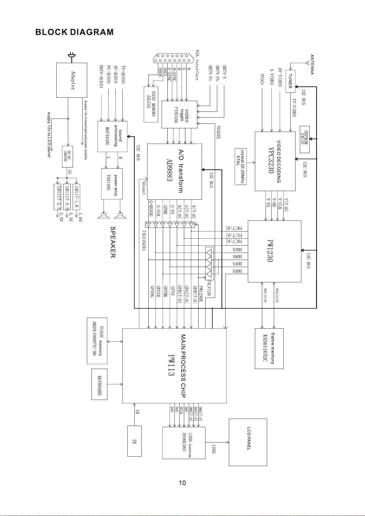
BLOCK DIAGRAM…………………………………………………………….……………
IC BLOCK DIAGRAM………………………………………………………………………..
Wiring diagram……………………………………………………………..……………....
Serial NO. of parts…………………………………………………………………………….…
Identification criteria for the bright spot and dark spot of the LCD screen………..….
Troubleshooting guide………………………………………………………………..……
Exploded views…………………………………………………………………………..…
Schematic diagram…………………………………………………………………….…..
1
2
6
8
10
11
20
21
21
22
26
28
Page 3

Attention: This service manual is only for service personnel to take reference with. Before servicing
please read the following points carefully.
Safety instructions
1. Instructions
1.1 Be sure to switch off the power supply before replacing or welding any components or
inserting/plugging in connection wire
1.2 Anti static measures to be taken (throughout the entire production process!):
a) Do not touch here and there by hand at will;
b) Be sure to use anti static electric iron;
c) It’s a must for the welder to wear anti static gloves.
1.3 Please refer to the detailed list before replacing components that have special safety
requirements. Do not change the specs and type at will.
2. Points for attention in servicing of LCD
2.1 Screens are different from one model to another and therefore not interchangeable. Be sure to use
the screen of the original model for replacement.
2.2 The operation voltage of LCD screen is 700-825V. Be sure to take proper measures in protecting
yourself and the machine when testing the system in the course of normal operation or right after
the power is switched off. Please do not
touch the circuit or the metal part of the module that is in operation mode.
Relevant operation is possible only one minute after the power is switched off.
2.3 Do not use any adapter that is not identical with the TV set. Otherwise it will cause fire or damage
to the set.
2.4 Never operate the set or do any installation work in bad environment such as wet bathroom,
laundry, kitchen,or nearby fire source, heating equipment and devices or exposure to sunlight etc.
Otherwise bad effect will result.
2.5. If any foreign substance such as water, liquid, metal slices or other matters happens to fall into the
module, be sure to cut the power off immediately and do not move anything on the module lest it
should cause fire or electric shock due to contact with the high voltage or short circuit.
2.6. Should there be smoke, abnormal smell or sound from the module, please shut the power off at
once. Likewise, if the screen is not working after the power is on or in the course of operation, the
power must be cut off immediately and no more operation is allowed under the same condition.
2.7. Do not pull out or plug in the connection wire when the module is in operation or just after the power
is off because in this case relatively high voltage still remains in the capacitor of the driving
circuit.Please wait at least one minute before the pulling out or plugging in the connection wire.
2.8. When operating or installing LCD please don’t subject the LCD components to bending, twisting or
extrusion, collision lest mishap should result.
2.9 As most of the circuitry in LCD TV set is composed of CMOS integrated circuits, it’s necessary to pay
attention to anti statics. Before servicing LCD TV make sure to take anti static measure and
ensure full grounding for all the parts that have to be grounded.
1
Page 4
2.10.There are lots of connection wires between parts behind the LCD screen. When servicing or
moving the set please take care not to touch or scratch them. Once they are damaged the screen
would be unable to work and no way to get it repaired.
2.11. Special care must be taken in transporting or handling it. Exquisite shock
vibration may lead to breakage of screen glass or damage to driving circuit.
Therefore it must be packed in a strong case before the transportation or
handling.
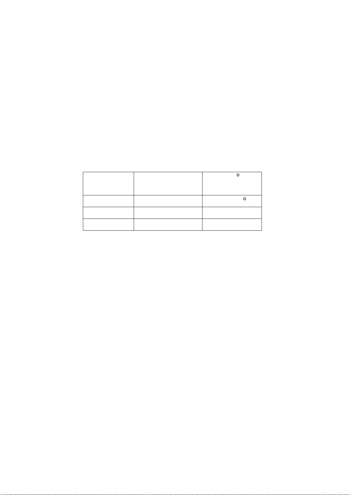
2.12. For the storage make sure to put it in a place where the environment can be controlled so as to
prevent the temperature and humidity from exceeding the limits as specified in the manual. For
prolonged storage, it is necessary to house it in an anti-moisture bag and put them altogether in
one place. The ambient conditions are tabulated as follows:
Scope for operation
0----+50 C
Temperature
Scope for storage
humidity Scope for operation
Scope for storage
2.13. Display of a fixed picture for a long time may result in appearance of picture residue on the screen,
as commmonly called “ghost shadow”. The extent of the residual picture varies with the maker of
LCD screen. This phenonmenon doesn’t represent failure. This “ghost shadow” may remain in the
picture for a period of time (several minutes).But when operating it please avoid displaying still
picture in high brightness for a long time.
-20----+60 C
20%---85%
10%---90%
3. Points for attention during installation
3.1. The front panel of LCD screen is of glass. Wheng installing it please make sure to put it in place.
3.2. For service or instatallation it’s necessary to use specified screw lest it should damage the screen.
3.3. Be sure to take anti dust measures. Any foreign substance that happens to fall down between the
screen and the glass will affect the receiving and viewing effect
3.4. When dismantling or mounting the protective partition plate that is used for anti vibration and
insulation please take care to keep it in intactness so as to avoid hidden trouble.
3.5. Be sure to protect the cabinet from damage or scratch during service, dismantling or mounting.
Description of adjustment and calibration
2.1 Adjustment and calibration equipment
Multi-meter,5515 signal generator and oscilloscope
PC set (FLASH writing programs should be installed in place first.), K7253 (VGA and YprPb signal
generator) CA210 (LCD white balancer) and DVD broadcast player.
2.2 Flow of adjustment and calibration
2
Page 5
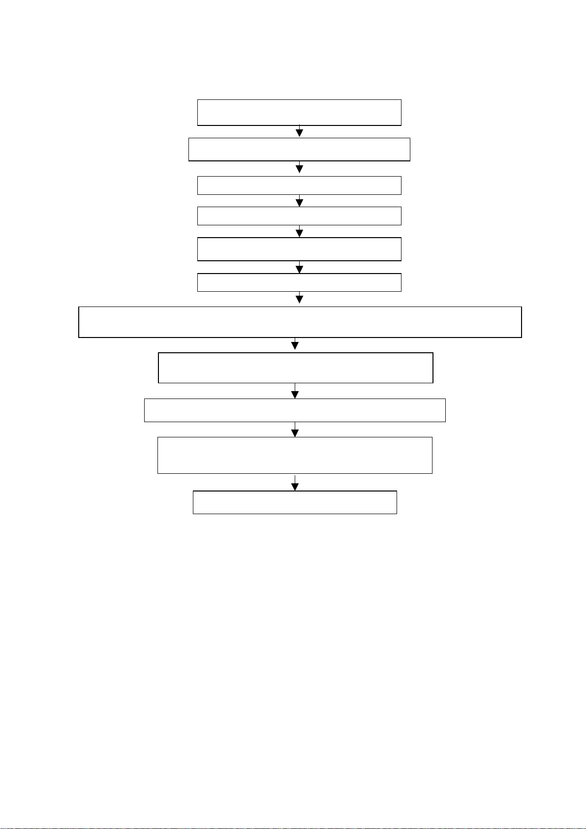
See Fig.1.
y
)
(
Adj
Check if memory U16 has been FLASH written.
Production of main board and TV board on the line.
usting and calibrating TV board
Check the main board
Check TV board
Combined test for general assembl
Connect to central signal source, check if various TV functions (station skipping, system identification, analog
control etc
are normal and check if earphone and speaker output are normal
Input VGA signal and check if display is normal in the state of PC
and various functions
analog control, line/field center etc.
Input AV/S signal and check various functions under AV/S terminal
Input YprPb signal and check if display is normal in the state of PC
and various functions (analog control, line/field center etc
Check accessories and then packing
Fig.1 Flow process of adjustment
2.3 FLASH WRITE programs
FLASH WRITE memory N9.
2.4 Main board adjustment and calibration
a) Connect main board to infrared receiving board, turn off the power supply adapter switch and
insert the plug of power supply adapter output into main board.
b) Turn on power supply adapter, check to see indication lamp in red light and check the power
supply and confirm various power supplies as listed below:
1) Main power supply C137 anode 5 V±0.2 V
2) Main power supply C138 3.3 V±0.1 V
3) PW1230 main power supply C142 2.5 V±0.1 V
4) PW113 main power supply L21 1.8 V±0.1 V
5) VPC3230 power for analog terminal L24 anode 5 V±0.2 V
3
Page 6
6) Power for liquid crystal screen C159 anode 12 V±0.3 V
7) AD9883A power C410,C17 3.3 V±0.1 V
c) Connect VGA line, small conversion board of RS232 electric level and PC set, then run the
program for FLASH upgrading. Turn on the power adapter switch and then the indication lamp
of infrared receiving board should be in off state. About 4 minutes later, upgrading is completed
and the indication lamp turns red.
d) FLASH write DDC program
2.5 Adjustment and calibration of TV board
2.5.1 Connect main board, TV board and infrared receiving board. Turn on the power supply adapter
switch and the indication lamp of the infrared receiving board will be in green. Measure TV board
X2 and PIN3 = 5 V±0.2 V.
2.5.2 Press the menu twice in the TV state to enter the item of sound adjustment. Then move the
cursor to the item of equilibrium. Open the cover of remote control set. Press the mute key at the
upper left corner and enter the factory menu. Press the menu key again and you can see the
preset item of ex-works. Select this preset item and press volume key (+ or -) once to execute
the ex-works presetting. The press confirm key to exit the factory menu.
2.5.3 Press channel key +/- to access the ex-works preset channel and check if the screen display is
normal.
2.6 Adjustment of white balance(Use white balance meter CA210 and signal generator K7253
specialized for LCD. )
2.6.1 Assemble the complete set.
2.6.2 Press “signal source” key to enter YpbPr.
2.6.3 Input signal YPbPr:640x480p 60 Hz (K7253).
2.6.4 Enter user menu and set the brightness to 50 and contrast to 50. Press factory key to enter
factory menu. Input dark field and execute “black calibration”. The input white field, execute
“white calibration” and then finish.
2.6.5 It’s unnecessary to do white balance adjustment for other channels.
2.6.6 For color coordinates, refer to Table 1.
Table 1 Color temperature coordinates
Color temperature Color coordinate X Color coordinate Y
9300K 0.281±0.020 0.311±0.020
7300K 0.298±0.020 0.321±0.020
6500K 0.313±0.020 0.329±0.020
3 Performance check
3.1 Station searching function of TV
Enter station searching menu→auto station search. Connect RF port to central signal source.
After system is set up, check if there is station skipping. Check the semi-auto search and see if
the fine adjustment is normal.
3.2 AV/S terminals
a) Connect AV and S terminals and check if they are normal.
b) Press the video key of the remote control and switch the picture frame
to the state of AV and S-VIDEO. Check if the color is normal and if there are mixed lines, snow
4
Page 7

flakes, abnormal tremble, interfering patterns or shifting. Plug the earphone line into the
earphone port and check to ensure that sound should be heard from both the left and right
sound channels.
3.3 YPbPr port
Press the video key of the remote control and switch the picture frame
to the state of YPbPr. Connect signals 1080I,720p and 480p. Check if the color is normal and if
there are mixed lines, snowflakes, abnormal tremble, interfering patterns or shifting. Plug the
earphone line into the earphone port and check to ensure that sound should be heard from
both the left and right sound channels.
3.4 YcbCr port
a) Connect YcbCr signal and press the key on the remote control to check if the color is normal
and if there are mixed lines, snowflakes, abnormal tremble, interfering patterns or shifting on
the picture.
b) If there is substandard product turned out, make a note on the flow card and route the product
onto the service line.
c) Plug the earphone line into earphone port and check to ensure sound should
be heard from both the left and right channels.
d) Furthermore, check if the different functions as listed in the menu are normal. For example, the
adjustment for brightness, contrast, saturation degree, and acutance is normal, alt and bourdon
are normal, and language, screen-display position/background and scaler are normal.
3.5 VGA port
Insert the connector of VGA signal. Separately input the three signals of VGA format as listed in
Table 2. After auto calibration is over, check if the display is normal. If there occurs interference on
the picture, press the auto setting key on the remote control once more and check if the display is
normal.
Table 2 VGA display format
Item
VGA display format
No.
1 640x480@60 Hz
2 800x600@60 Hz
3 1024x768@60 Hz
4 Preset before ex-works
Enter factory menu in the TV state and then perform setting for ex-works.
5 Packing for ex-works
Check accessories and then packing.
5
Page 8
Trouble shooting
Before servicing please check to find the possible causes of the troubles according to the table below.
1.Antenna:
Picture is out of focus or jumping Bad status in signal receiving
Maybe broadcast signal itself is not good
Check if the outdoor antenna is disconnected.
Check if the antenna is correctly oriented.
Fringe in picture Check if the antenna is correctly oriented.
Maybe there is electric wave reflected from hilltop or building.
Picture is interfered by stripe
shaped bright spots
There appear streaks or light color
on the screen
Possibly due to interference from automobile, train, high
voltage transmission line, neon lamp etc.
Maybe there is interference between antenna and power
supply line. Please try to separate them in a longer distance.
Check if interfered by other equipment and if interfered
possibly by the equipment like transmitting antenna, non
professional radio station and cellular phone.
6
Page 9
2.TV set:
Symptoms Possible cause
Unable to switch the power on Check to see if the power plug has been inserted properly into
the socket.
No picture and sound Check to see if the power supply of liquid crystal TV has been
switched on. (as can be indicated by the red LED at the front
of the TV set)
See if it’s receiving the signal that is transmitted from other
source than the station
Check if it’s connected to the wrong terminal or if the input
mode is correct.
Check if the signal cable connection between video frequency
source and the liquid crystal TV set is correct.
Deterioration of color phase or color
tone
Screen position or size is not proper Check is the screen position and size is correctly set up.
Picture is twisted and deformed Check to see if the picture-frame ratio is properly set up.
Picture color changed or colorless Check the “Component” or”RGB”settings of the liquid crystal
Picture too bright and there is
distortion in the brightest area
Picture is whitish or too bright in the
darkest area of the picture
No picture or signal produced from
the displayer if “XXX in
search”appears.
There appears an indication -
“outside the receivable scope)
Remote control cannot work
properly
No picture and sound, but only
hash.
Check if all the picture setups have been corrected.
TV set and make proper adjustment according to the signal
types.
Check if the contrast setting is too high.
Possibly the output quality of DVD broadcaster is set too high.
It maybe also due to improper terminal connection of the video
frequency signal in a certain position of the system.
Check if the setting for the brightness is too high
Possibly the brightness grade of DVD player(broadcaster)is
set too high.
Check if the cable is disconnected.
Check if it’s connected to the proper terminal or if the input
mode is correct.
Check if the TV set can receive input signal. The signal is not
correctly identified and VGA format is beyond the specified
scope.
Check if the batteries are installed in the reverse order.
Check if the battery is effective.
Check the distance or angle from the monitor.
Check if there is any obstruct between the remote control and
the TV set.
Check if the remote control signal- receiving window is
exposed to strong fluorescence.
Check if the antenna cable is correctly connected, or if it has
received the video signal correctly.
7
Page 10
Blur picture Check if the antenna cable is correctly connected.
Of if it has received the right video signal.
No sound Check if the “mute” audio frequency setting is selected.
Check if the sound volume is set to minimum.
Make sure the earphone is not connected.
Check if the cable connection is loose.
When playing VHS picture search
tape, there are lines at the top or
bottom of the picture.
When being played or in pause VHS picture search tape
sometimes can’t provide stable picture, which may lead to
incorrect display of the liquid crystal TVIn this case please
press “auto” key on the remote control so as to enable the
liquid crystal TV set to recheck the signal and then to
display correct picture signal
Method of softwar e upgrading
Steps of software upgrading are as follows:
1. Select a serial connection wire and a VGA connection wire and then connect them by means of a
patch panel;
2. Use a serial wire to connect the PC to the patch panel and set TV set to off state;
3. Open the software upgrade file holder and double click
FlashUpgraderNT(use under window 2000/XP/NT)
FlashUpgrader(use under window 98),
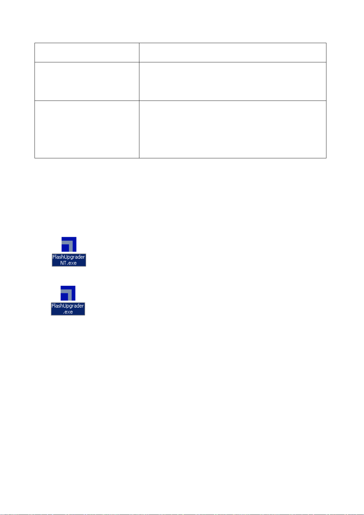
The following interfaces will show up after running the program:
8
Page 11
Based on the computer features, set up the serial port(COM Port). Select corresponding serial port
(if it’s unable to FLAS H WRITE, change t o another port) . Baud is se lected to be 115200. Then select
Reset Target After Download. Click FLASH pushbutton, it’s ready to run. For other settings, please
refer to the Fig. Above (already defaulted by the system, normally no need t o change).
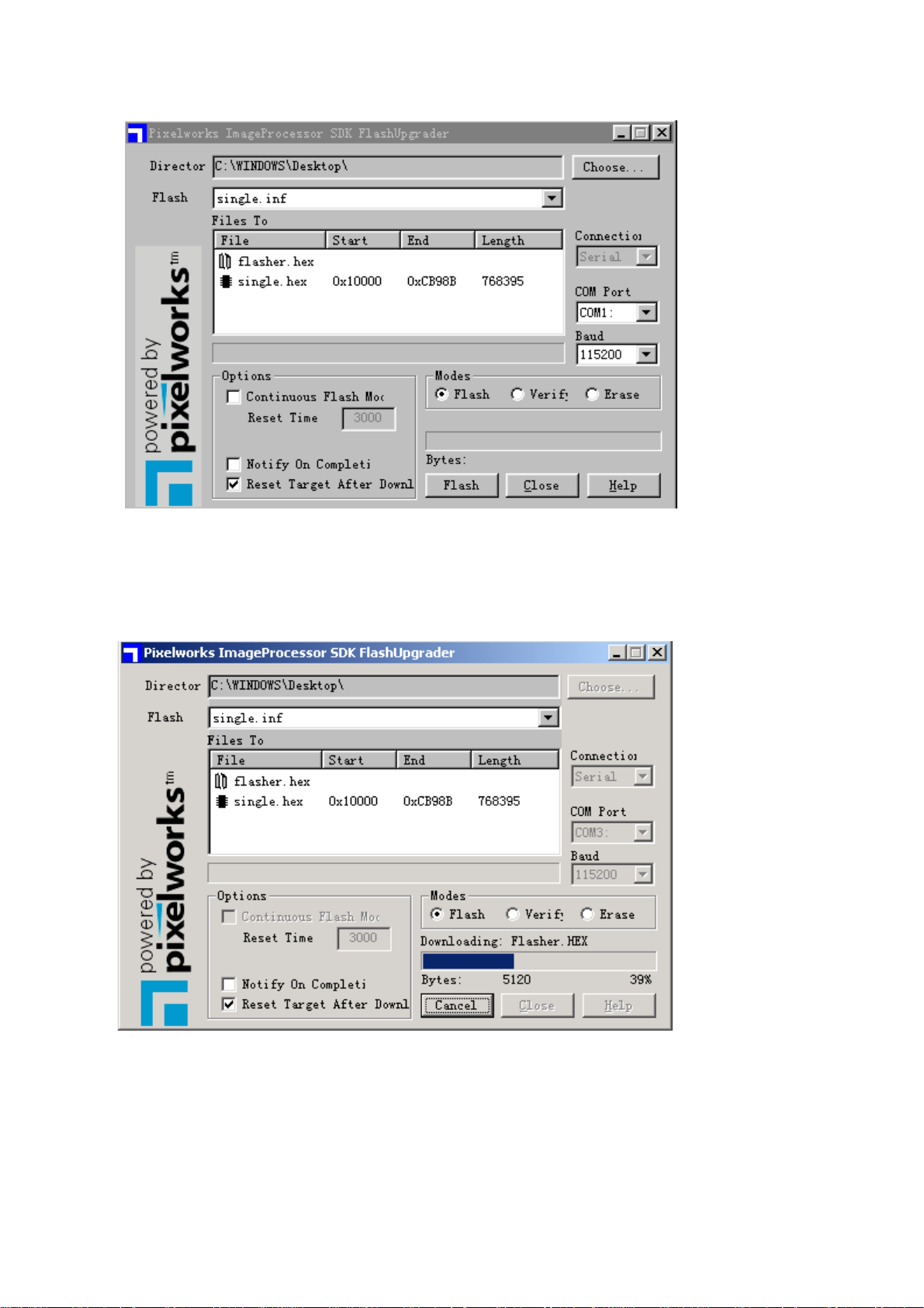
4. Switch on TV set the FLASH wr it e program begins t o run;
5. After FLASH write is over, push button “cancel” will become flash. Then shut the main power supply
and it’s OK just switch it on again.
Note: Do not shut the power off or turn the TV set on during the FLASH write. Otherwise it may
lead to no way for flash to rewrite.
9
Page 12
Page 13

IC Block Diagram
1 PW113(N15)
PW113 is the MCU of this TV set and is also its core chip. It communic ates w ith v arious other chips
by means of bus line 12. The work it performs includes picture scaling (SCALER), receiving of external
control signals, sending of various control signals to corresponding signal processing chips so as to
complete relevant function s. Picture signa l is input th rough GPOR T of P W113 to SCALER for processing.
The processed signal is output through GPORT as R,G,B signal and D-HS (line synchronizing), D-VS
(field synchronizing), DCLK (82 MHz clock signal) and D-EN (enable signal). The external control signal
received by PW113 includes IRIN of Pin203 (signal received by remote control), KEY [2-7] of PORTA
(push key control signal) and reset signal etc. Major control signa ls outp ut fro m P W113 include backlight
control signal BKLON(Pin 40), Panel power supply control signal LCDON(Pin 39), PI5V330 selective
control signal VAGSEL(Pin 43), backlight adjustment signal PWMOUT(Pin 200), power amplification
mute control signal MUTE(Pin 20 1), LED l a mp contr ol sig nal LE D7( Pin 46, to be high elect r ic lev el whe n
switched on) and selective signals for certain chips.
Block diagram for PW113 system
11
Page 14

12
Page 15

2 PW1230(N11)
The major function of PW 1230 is to convert the interlaced video signal into line-by-line video signal
so that the picture is clearer and realer and the picture frame becomes finer an d smoother. In addition to
this con ve rsi on fu nct i on PW1230 is capab le o f en hanc i ng t he image and can also be used to adjust the
brightness and contrast of the channe l. Nevert heles s, t he brightnes s and co ntrast adju stm ent funct ion o f
this TV set is performed by regulating the front end VPC3230. After the digital video signal received by
PW1230 from VPC3 230 is deint er lac ed, it is out put a s 24b it dig it a l RG B s ignal to GPORT of N15 PW113
where it is processed. The output signals as DDCK (CLOCK), DDVS (FIELD SYNCHRONIZING),
DDHS(LINE SYNCHRONIZING), DDEN (ENABLE SIGNAL) are also basic references for the
processing of lower level.
13
Page 16

3 VPC3230(N10)
The block diagram of VPC3230 is shown as below:
2
In which:
71 pin CIN is signal input for S-VIDEO;
73 pin VIN2 is CVBS input for AV;
74 pinVIN3 is for TV signal input;
75 pinVIN4 is used for synchronous identification of YCRCB.
Pins 5,4,6 are respectively used for YCBCR signal input.
Pins 62 and 63 are connected to crystal oscillator of 20.25MHz and supply local frequency to
VPC3230.
Pins 13,14 are SAF AND SCL signals for bus line 12 to be used for communication with MCU
PW113.
VPC3230 that is used as video decoding chip sends the digital video signal in the format of
CCIR601, which is decoded from the analog video signal CVBS,S-VIDEO,YCBCR, to the deinterlacing
processor N11 PW1230 where conversion is made from interlace to non-interlace. VINCK, VHREF,
VINHS and VINVS sent out by VPC3230 are directly fed to PW1230.
4 SI9933ADY(17)
S
1
S
2
G
1
DD
11
P-Channel MOSFET
14
G
2
DD
22
Page 17

5 TDA7495(U601)
The block diagram of TDA7495 is shown below.
In which
Pins 1,5 are for input of left and right sound channels.
Pin 9 is control pin when STBY (valid when it is of low electr ic level).
Pin 10 is control pin for MUTE (valid when it is of high electric level).
Pin 13 is power supply pin for IC (24V).
Pins 12,14 are for power amplification output (output electric level is 10V).
For TDA7495, only when two control pins 9 and 10 are valid at the same time can there be sound
output. When servicing with power on please take care not to short circuit the IC pin or the power supply
because IC is liable to burnout.
6 24LC21(N3)
15
Page 18

7 MSP3450(U5)
MSP3450 is an audio processing chip. It has four pairs of audio input ports, which are respectively
TV , PC-AUDIO, HD-R HD-L, AV-R AV-L. The four groups of inputs connected through bus l ine 12 to
PW113 , which contr ol t he audio signal cor r e sponding to t he output according t o dif ferent SO URCES.
8 AD9883(N6)
16
Page 19

9 K4S641632C(N12)
10 DS90C383A(N16)
DS90C 383A/D S 90C F383A
17
Page 20

11 Z86129 (N8)
18
Page 21

12 LVC16244(N13 N14)
13 PI5330(N1)
14 74LV126(N4)
19
Page 22

Page 23

Serial No. of Parts
667-L30B1-83 Signal processing board
667-L30B1-15 Amplifier board
667-L30B1-40 TV board
667-L30B1-09 Remote sensor board
667-L32B1-05 Key board
302-L30B1-01 Power adapter board
535-L30B1-01 Wall mounting parts
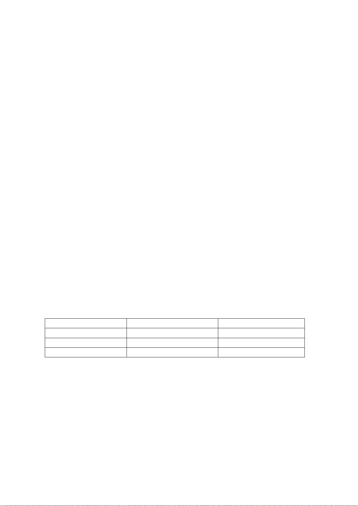
Identification criteria for the bright spot and dark spot of the LCD screen
Category criteria
One single
Bright
spo
t
Dark
spots
Total defected point ≤8 ≤7 ≤5 ≤4 /
Notes:
1. Definition of defected point (bright spot, dark spot): It is identified as a defected point if its
2. Definition of bright spot: It is identified as a bright spot if it is bright in the state of dark field
3. Definition of dark spot: It is identified as a dark spot if it is dark in the state of white field and
4. Definition of two neighboring points: Defects of a group of picture elements(RB,RG,GB).
spot
2 neighboring
spots
Total No. ≤5 ≤2 ≤5 ≤2 ≤3
One single
spot
Two
neighboring
spots
Total No. ≤6 ≤7 ≤5 ≤4 ≤10
area exceeds 1/2 of a single picture element (R,G,B).
and its bright size remains unchanged
its dark size remains unchanged
15" 20" 22" 30" 40" 15" 20" 22" 30" 40"
≤5 ≤2 ≤5 ≤2 ≤3
≤2 ≤1 ≤2 ≤1 ≤1
≤6 ≤7 ≤5 ≤4 ≤10
≤2 ≤2 ≤2 ≤1 ≤5
Q’ty allowed Distance between two spots
≥15mm
≥15mm
≥10mm
≥5mm
21
Page 24

TROUBLESHOOTING GUIDE
r
r
k
NO RASTER
Indicator whethe
yes yes
light
no no
no
Replace
adapter
yes
no
Replace
N17
yes
yes
Replace PANEL
no
Check whethe
N25 Pin 7 is high
level
test X17 pin 1 and 2 and chec
whether the voltage is 12V and
24V
Check whether N17 pin
5 the voltage 12V
Check X21 pin
9.10.11.12.16.17.1
8.19.20waveform
Replace signal
processing board
Replace N25
22
Page 25

NO PICTURE( HAVE RASTER)
Fault 1.VGA and YPBPR no picture
Check N1 pin 12
yes no
waveform
no yes
yes
Replace N1 PI5V330
no
no
no
Check N15 pin 170 waveform Replace G2
Check R21 R131
pin waveform
Check R89 pin
waveform
Replace N15 PW113
Replace N6 AD9883
Replace N16
DS90C383A
23
Page 26

Fault 2. AV S-VIDEO and YCBCR no picture
Check R55 R56
no no
R57 pin waveform
yes
yes
no no
Check R64 R65
R66 pin waveform
no
yes
Check R82 R89
R93 pin
yes
no
Check N15
no
pin170 waveform
yes
Replace N15
Check N11 pin62
waveform
Replace N10
Check N16 pin40
waveform
Replace N11
Replace N16
Replace G2
Replace G1
Replace G3
24
Page 27

Fault 3. TV no picture
r
V
r
r
yes
Check X4 pin2
waveform
no
Replace TV board
Check fault 2
NO SOUND
no no
Check X601 pin 1
and 3 waveform
yes
yes
yes
Check whethe
U601 pin13 the
voltage 24V
no
Check adapte
power
Check U5 pin 24
and 25 waveform
Replace U26
Replace sound amplife
board
Replace T
board
25
Page 28

EXPLODED VIEWS
8
1
2
3
4
5
6
7
9
19
15
18
17
14
16
13
12
10
11
26
Page 29

NO. NAME NO. NAME
1 Speaker’s front cover 11 Stand base
2 speaker 12 screw
3 Sound-leading part 13 back cover board
4 Speaker’s back cover 14 screw
5 Speaker connector 15 parts of keys
6 Front cabinet 16 back cabinet
7 LCD screen connecting frame 17 Fixing f r ame
8 LED column 18 main board
9 LCD panel 19 main board frame
10 Signal cable supporter
27
Page 30

Page 31

Page 32

Page 33

Page 34

Page 35

Page 36

Page 37

87654321
Name: TV DECODER
9V
R516 10K
R51910K
X1
D
R95
10K
AUDIO-OUT
C
J12
R517 10K R51810K
CJ2
10u
U26
LM358
1
A-out
A-in
R96
10K
1
2
3
4
5
C65
1u
C66
1u
2
3
4
A-in
GND
B-out
B-in
B-in
CK5
8VCC
7
6
5
0.1
26 27
C65
100n
C74
1n
C66
100n
C73
1n
25
DACM_L
C72
1n
24
DACM_R
23
VREF2
C71
1n
22
DACA_L
C70
21
DACA_R
1n
20
RESET
C509
0.1u
19
NC
C80
16V 10u
18
I2S_I2
C81
0.1u
C82
470p
17
DVSS
16
DVSUP
L506
10uH
15
ADR_CL
5V-1
14
ADR_WS
13
ADR_DA
12
I2S_I1
11
I2S_DO
D
5V-1
U5
MSP3450G
10
9
I2S_CL MONO
8
SDA AVSS
7
SCL
6
STANDBY
5
A_SEL AN_IN-
4
D/CTR AN_IN2
3
D/CTR
1
2
AUD_CL_OUT
J7
VIDEO-OUT
AN_IN1
SC2_ORDACM_S
SC2_OL
VREF1
SC1_OR
SC1_OL
CAPL_A
AHVSUP
CAPL_M
AHVSS
AGNDC
SC3_L
SC3_R
SC2_L
SC2_R
SC1_L
SC1_R
VREF_TI2S_WS
AVSUP
TEST
XT_IN
C
X2
C508
16V 100u
28
29
30
31
32
33
34
35
36
37
38
39
40
41
42
43
44
45
46
47
48
49
50
51
Z1
18.432M
52TP XT_OUT
C64
33p
B
TV-VIDEO
C521
47p
C501
0.1u
14
5V
LD
10uH
15
CJ4
16V 470u
C85
5V-1
470p
C84
0.1u
C83
10u
LB
10uH
C510
56p
C62
10u
5V-1
R522
0
25
C503
16V 10u
C54
0.33
C32
0.1u
L503
10uH
L51010uH
R524
0
21
22
23
19
20
24
L504
10uH
TV-SIF
C61
10u
C88
470p
C87
0.1u
C86
10u
C77
4.7u
C78
0.1u
C60
0.33u
R505
10K
C59
0.33u
R506
10K
C58
0.33u
R504
10K
C57
0.33u
R503
10K
C56
0.33u
R502
10K
C75
10u
C55
0.33u
R501
10K
C76
0.1u
R514R515
C52
56p
C63
33p
5V
AV-OUT
RESET
SCL
B
+12V
U3
3
2
1
BB1117-5
R525
100
SDA
16V 470uF
CJ5
9V SUPPLY
C511
0.1uF
C512
0.1uF
R520
R521
C33
0.1u
4.7k
4.7k
C502
16V 10u
11
9
12
C520
47p
13
NC
U2
A
JS-2F/134
1 2 3 4 5 6 7 8
VTMON
VCC
SCL
SDA
NC16NC17NC18NC
ASEL
TV-SIF
IF-TV-VIN
SIFOUT
CVBS
VCCIF
AFOUT
J10
PC-AUDIO
J9
HD
HD-L
HD-R AV-L AV-R
J8
AV
A
Page: 8
Page 38

87654321
AUDIO
Name: AUDIO
D
D
U601
TDA7495
IN_L
VAR_L
VOLUMN
VAR_R
IN_R
NC
SVR
SGND
STBY
MUTE
PGND
OUR_R
VCC
OUT_L
14
15
L601
10uH
C616
25V 1000u
PGND
L603
75uH
L602
10uH
C612
0.1u
C617
0.1u
VD604
RGP10
1
X602
L_OUT
R_OUT
C
X601
1
2
3
4
5
6
7
8
9
10
11
12
C608
VD601
5Z1
13
C615
35V 470u
C614
0.1u
C
IN_L
1
C602
16V 2.2u
5V
R602
R601
1K
1K
IN_R
R603
1K
C604
16V 2.2u
C603
100n
25V 470u
V601
RN1204
C606
5V
R604
10K
J4
0
R605
10K
R606
3.3K
C607
25V 1u
C611
35V 470u
25V 1u
X603
MUTE
B
STBY
J11
0
J9
空
V602
RN1204
J1
空
C609
0.1u
5V
C613
25V 47u
R608
1/4W 3.6K
D602
5Z1
C610
25V 47u
R607
10K
VD603
IN4148
V603
2SC1015
R609
10K
R610
10K
B
1
A
A
Page: 9
1 2 3 4 5 6 7 8
 Loading...