

Page 1
LCD TELEVISION
LC-27U26
Page 2

CONTENTS
Safety precautions………………………………………………………………………..…
Alignment instructions …………………………….…….……………………………….…
Working principle analysis of the unit……………………………….………….………….
Block diagram…………………………………..………………………. ……………………
IC block diagram………………………………………………………………………..……
Wiring diagram ……………………………………………………………..……………...
Troubleshooting………………………………………………………………………..……
Schematic diagram …………………………………………………………………….…..
APPENDIX-A: Main assembly list
APPENDIX-B: Exploded views
1
3
6
7
8
15
16
22
Page 3

Attention: This service manual is only for service personnel to take reference with. Before
servicing please read the following points carefully.
Safety precautions
1. Instructions
Be sure to switch off the power supply before replacing or welding any components or
inserting/plugging in connection wire Anti static measures to be taken (throughout the entire
production process!):
a) Do not touch here and there by hand at will;
b) Be sure to use anti static electric iron;
c) It’s a must for the welder to wear anti static gloves.
Please refer to the detailed list before replacing components that have special safety requirements.
Do not change the specs and type at will.
2. Points for attention in servicing of LCD
2.1 Screens are different from one model to another and therefore not interchangeable. Be sure to
use the screen of the original model for replacement.
2.2 The operation voltage of LCD screen is 700-825V. Be sure to take proper measures in
protecting yourself and the machine when testing the system in the course of normal operation or
right after the power is switched off. Please do not touch the circuit or the metal part of the module
that is in operation mode. Relevant operation is possible only one minute after the power is
switched off.
2.3 Do not use any adapter that is not identical with the TV set. Otherwise it will cause fire or
damage to the set.
2.4 Never operate the set or do any installation work in bad environment such as wet bathroom,
laundry, kitchen, or nearby fire source, heating equipment and devices or exposure to sunlight etc.
Otherwise bad effect will result.
2.5 If any foreign substance such as water, liquid, metal slices or other matters happens to fall into
the module, be sure to cut the power off immediately and do not move anything on the module lest it
should cause fire or electric shock due to contact with the high voltage or short circuit.
2.6 Should there be smoke, abnormal smell or sound from the module, please shut the power off at
once. Likewise, if the screen is not working after the power is on or in the course of operation, the
power must be cut off immediately and no more operation is allowed under the same condition.
2.7 Do not pull out or plug in the connection wire when the module is in operation or just after the
power is off because in this case relatively high voltage still remains in the capacitor of the driving
circuit. Please wait at least one minute before the pulling out or plugging in the connection wire.
2.8 When operating or installing LCD please don’t subject the LCD components to bending, twisting
or extrusion, collision lest mishap should result.
2.9 As most of the circuitry in LCD TV set is composed of CMOS integrated circuits, it’s necessary
to pay attention to anti statics. Before servicing LCD TV make sure to take anti static measure and
ensure full grounding for all the parts that have to be grounded.
2.10 There are lots of connection wires between parts behind the LCD screen. When servicing or
moving the set please take care not to touch or scratch them. Once they are damaged the screen
1
Page 4
would be unable to work and no way to get it repaired.
If the connection wires, connectors or components fixed by the thermotropic glue need to disengage
when service, please soak the thermotropic glue into the alcohol and then pull them out in case of
dagame.
2.11 Special care must be taken in transporting or handling it. Exquisite shock vibration may lead to
breakage of screen glass or damage to driving circuit. Therefore it must be packed in a strong case
before the transportation or handling.
2.12 For the storage make sure to put it in a place where the environment can be controlled so as to
prevent the temperature and humidity from exceeding the limits as specified in the manual. For
prolonged storage, it is necessary to house it in an anti-moisture bag and put them altogether in one
place. The ambient conditions are tabulated as follows:
Temperature Scope for operation 0 ~ +50 oC
Scope for storage -20 ~ +60 oC
Humidity Scope for operation 20% ~ 85%
Scope for storage 10% ~ 90%
2.13 Display of a fixed picture for a long time may result in appearance of picture residue on the
screen, as commonly called “ghost shadow”. The extent of the residual picture varies with the
maker of LCD screen. This phenomenon doesn’t represent failure. This “ghost shadow” may remain
in the picture for a period of time (several minutes). But when operating it please avoid displaying
still picture in high brightness for a long time.
3. Points for attention during installation
3.1 The front panel of LCD screen is of glass. When installing it please make sure to put it in place.
3.2 For service or installation it’s necessary to use specified screw lest it should damage the screen.
3.3 Be sure to take anti dust measures. Any foreign substance that happens to fall down between
the screen and the glass will affect the receiving and viewing effect
3.4 When dismantling or mounting the protective partition plate that is used for anti vibration and
insulation please take care to keep it in intactness so as to avoid hidden trouble.
3.5 Be sure to protect the cabinet from damage or scratch during service, dismantling or mounting.
2
Page 5
Alignment instructions
r
1. Test equipment
PM5518 (video signal generator)
K-7253 (VGA signal generator)
CA210 (white balancer)
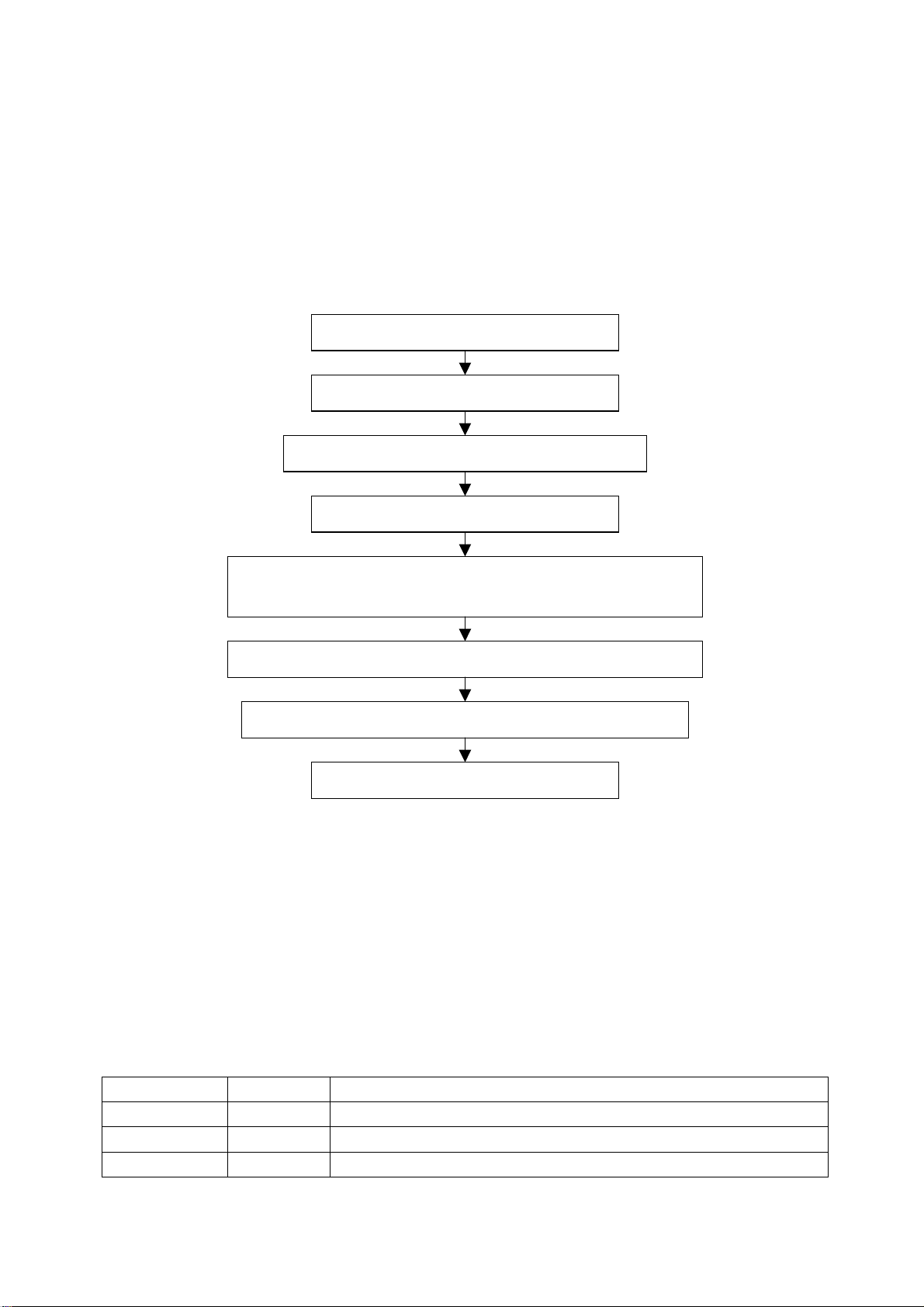
2 Alignment flow-chart
The alignment flow-chart is shown as fig-1
Check DDC, HDCP KEY and CPU
Factory initialization setup
IF channel voltage of TV and AGC voltage adjustment
Support format of VGA pre-set
Adjustment for sub-brightness and white balance of VGA/HDMI (colo
temperature 6500k, 9300k and 12000k)
Adjustment for sub-brightness and white balance of YPbPr/YcbCr channel
Adjustment for sub-brightness and white balance of VIDEO channel
Fig-1 adjustment flow-chart
3 Unit adjustments
Connect digital board, CPU board and analog board according to wiring diagram, connect with
power and observe the display.
Method for entering factory menu: press “SLP”, “DSP”, “MENU” and “DSP” in turn to enter factory
menu; press “CH+” and “CH-” to select adjustment items and press “VOL+” and “VOL-” to adjust
value items, press “MENU” to exit.
Note: the white balance adjustment should be done under “nature” picture mode.
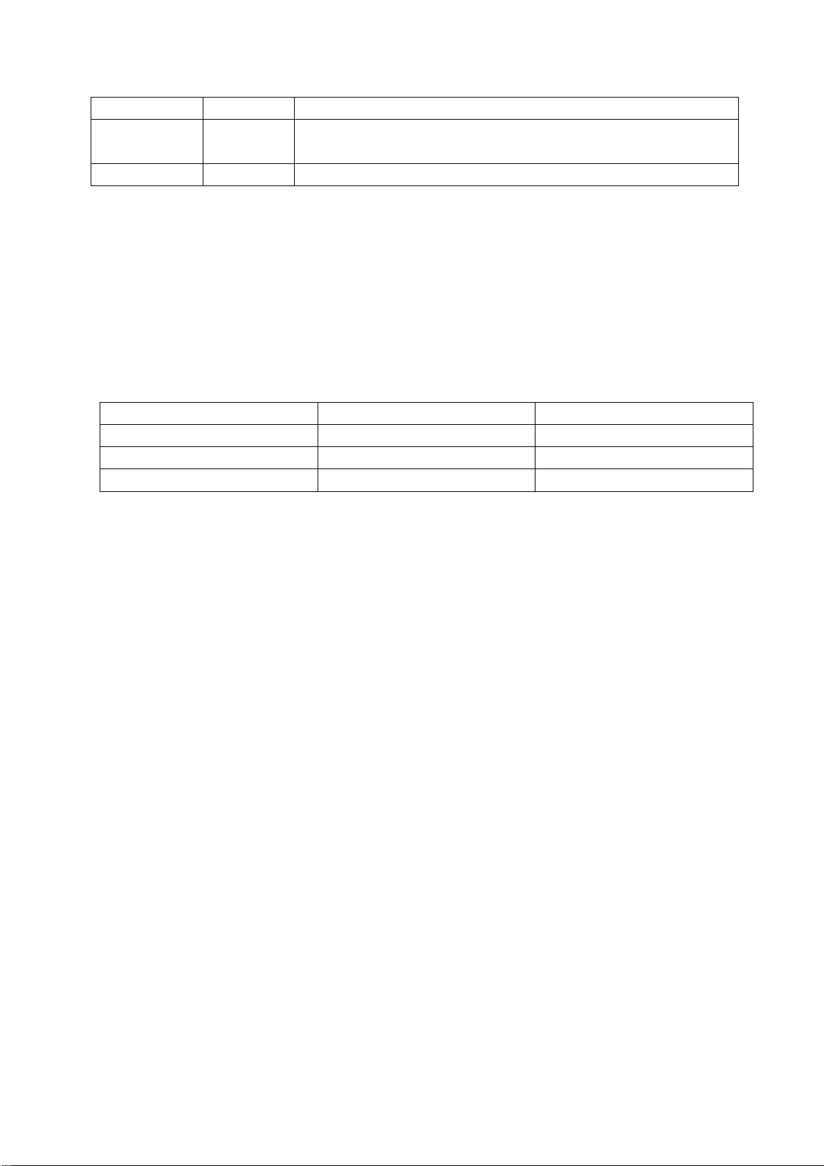
3.1 Initialization
Enter factory menu, select “Factory settings” sub-menu, and adjustment for items of table1.
Table1 sub-menu adjustment
Items Range Introduce
PW on LOGO ON/OFF Display 5s LOGO of turn on the TV
NO Sig LOGO ON/OFF If display LOGO in no signal
Black Screen BLUE/BLACK If display blue screen and white noise wave in no signal, setting “BLUE”
Preset ex-factory
3
Page 6
MLK 120-159 Adjustment for clock frequency (MHz) of memorizer, setting “145”.
PIP Size Middle/Large Select two component of PIP: “SMALL AND MIDDLE” and “SMALL AND BIG”,
setting “MIDDLE”.
init EEprom Start? Eeprom Initialization (adjustment for EEprom data)
3.2 Adjustment for AFT voltage and AGC voltage of IF channel in TV
Input frequency for 45.75MHz and IF signal for 80dBV of TP1, adjust L107 to value 2.4v of TP2;
when increase 0.10MHz of TP1 input signal, the TP2 value 1.0v at least; but decrease
0.10MHz of TP1 input signal, the TP2 value 4.0v at least.
3.3 VGA/DVI channel adjustment
3.3.1 Preset VGA channel mode
Input VGA signal (PATTERN: CROSS) of VG-849 or VG-848, select PROG850(640*400/85Hz),
auto adjustment until the screen is filled with picture. Use the same method to do auto adjustment
for the following items:
PROG851(640*480/72 Hz) PROG852(640*480/75 Hz) PROG853(800*600/56 Hz)
PROG854(800*600/60 Hz) PROG855(800*600/72 Hz) PROG856(1024*768/60 Hz)
PROG857(1024*768/70 Hz) PROG858(1280*768/75 Hz) PROG888(800*600/75 Hz)
PROG915(1152*870/75 Hz) PROG915 (1280*1024/60Hz)
3.3.2 Sub-brightness and White balance adjustment VGA/HDMI channel
a. Input VG-849 or VG-848 signal of VGA: PROG852(640* 480/75Hz) and eighth level gray-scale
signal of PATTERN. Use color analyzer CA210 to adjust sub-brightness and white balance.
b. Enter submenu of COLOR TEMP., Select 9300k of color temperature, set auto value of R, G and
B to 50. Enter submenu of white balance, preset value of offset_R, offset_G and offset_B to 125,
and preset value of gain-R, gain-G and gain-B to 100. Adjustment for brightness let the second level
brightness be 3nit at least.
c. Fixed value of offset_B, adjust offset_R and offset_G, let the color coordinate of the second level
be 285 and 293 and its brightness be 4-5nit more or less (it can not 3.5nit at least). Fixed value of
gain_B, adjust gain_R, gain_G and gain_B, let the color coordinate of seventh level be 285 and 293.
Adjustment offset_R, offset_G, offset_B, gain_R, gain_G and gain_B repeatedly until the value of
the two levels gray-scale be 285 and 293.
d. Select 6500k of color temperature, set auto value of R, G and B to 50. Fixed value of B to 50,
adjust R and G, let the color coordinate of the sixth level be 313 and 329. Adjust R and G repeatedly
until the color coordinate value to 313 and 329.
e. Select 12000k of color temperature, set auto value of R, G and B to 50. Fixed value of B to 50,
adjust R and G, let the color coordinate of the sixth level be 270 and 283. Adjust R and G repeatedly
until the color coordinate value to 270 and 283.
f. Input PROG852(640*480/75Hz) and the eighth level gray-scale of PATTERN signal of VG-849 to
HDMI, repeatedly the b-e course. In the HDMI channel, preset value of offset_R, offset_G and
offset_B to 15, preset value of gain_R, gain_G and gain_B to 25.
3.4 Adjustment for sub-brightness and white balance of YPbPr channel
a. Connect YPbPr signal of VG-849 and VG-848 to YPbPr terminal, input color signal of
PROG973(1080i)PATTERN964. Select AUTOTUNE item, wait for it displays “OK”. NOTE: Don’t
select AUTOTUNE item in other state.
4
Page 7

b. Switch YPbPR signal of VG-849 and VG-848 output to the eighth gray-scale signal of
PROG973(1080i)PATTERN964. prset value of offset_R, offset_G and offset_B to 15 and gain-R,
gain-G and gain-B to 25. adjust brightness, let second bright to 3nit at least.
c. Fixed value of offset_B, adjust offset_R and offset_G, let the color coordinate of the second level
be 285 and 293 and its brightness be 4-5nit more or less (it can not 3.5nit at least). Fixed value of
gain_B to 25, adjust gain_R, gain_G and gain_B, let the color coordinate of seventh level be 285
and 293. Adjustment offset_R, offset_G, gain_R and gain_G repeatedly until the value of the two
levels gray-scale be fixed.
d. Input PROG977(720p), PROG978(480p) and PROG968(480i) mode for eighth level gray-scale
signal, let the color coordinate of the second level and the seventh level 285 and 293.
3.5 VIDEO channel adjustment (TV/VIDEO/S-VIDEO)
a. Connect color bar signal of AV (PM5518, NTSC , eight level gray-scale signal) to VIDEO1
terminal, enter factory menu, preset value of offset_R, offset_G and offset_B to 15 and gain-R,
gain-G and gain-B to 25, adjust brightness, let second bright to 3nit at least.
b. Fixed value of offset-B to 15, adjust offset_R and offset_G, let the color coordinate of the second
level be 285 and 293 and its brightness be 4-5nit more or less (it can not 3.5nit at least). Fixed value
of gain_B to 25, adjust gain_R, gain_G and gain_B, let the color coordinate of seventh level be 285
and 293. Adjustment offset_R, offset_G, gain_R and gain_G repeatedly until the value of the two
levels gray-scale be fixed.
4 Performance check
4.1 TV function
Enter searching menu → auto search, connect RF-TV terminal with central signal source and check
if there are channels be skipped
4.2 AV/S, YpbPr terminals
Input AV/S, HD signal, check if it is normal.
4.3 VGA terminal
Insert VGA terminal, input VGA format signal of 640 X 480@60 Hz, check if the display is normal. If
interference exists, press the auto adjusts button on remote control again and check if it is normal.
4.4 HDMI terminal
Insert HDMI terminal, input signal of 640 X 480@60 Hz signal and check if the display is normal.
4.5 check sound channel
Check the speaker and headphone of each channel.
4.6 presetting before ex-factory
Item Setting Item Setting Item Setting
Picture mode NATURE OSD language English CCD OFF
Sound mode NORMAL HALFTONE 50 STEREO ON
N/R WEAK DURATION 30 VGA/HDMI NORMAL
SCREEN FULL MAG.C ON ANTENNA CATV
5
Page 8

Working principle analysis of the unit
The RF signal received by antenna will be sent to tuner, then IF signal will be obtained through high
amplifier and mixed frequency, through pre-intermediate amplified by V104, then it will be sent to
acoustic surface-wave Z103 to do IF filter and get better IF characteristics, then it will be sent to TV
board N101 (M52760E) to do intermediate amplification, phase-locked loop VCO and synchronous
wave detection to get composite video signal VIDEO; after pre-intermediate amplification IF will also
be sent to acoustic surface-wave Z102 to do filter at the same time, then it will be sent to N101 to do
intermediate amplification and demodulate audio signal (SIF).
The VIDEO signal output from M52760E together with video signals namely AV1 and AV2/S will be
sent to video decoder N601 (TVP5160) to de video selection, clamp, A/D transformation,
comb-shaped filter and color decode, then one way will output as video output of AV OUT, one way
will output 8bit CCIR656 format signal and CLK signal, then it will be sent to the main chip N101
(MST6151) of CPU; YpbPr, VGA and HDMI signals will also be sent to N101 (DVI interface can be
connected to HDMI interface through the use of a passive cable converter).The main chip
N101(MST6151) a multifunctional large-scale specified integrated circuit board, it has many kinds of
function such as A/D and D/A transformation, interleaved/ line-by-line processing, mode
transformation, low voltage differential output processing etc., then output four couples differential
signal and one couple clock signal.
The signals input from HDMI to MST6151 include audio signal, after processing in MST6151, it will
be sent to NA01 (CS4340) to do D/A transformation and then output audio signal L/R of HDMI.
Audio signal L/R of HDMI output from CS4340 output together with audio signal L/R of YPbPr and
VGA/DVI will be sent to audio processor N801 (MSP3425G) after selection by audio switch NA02
(HEF4052); L/R signal of AV1 and AV2/S via selected switch N701(HEF4052) will also be sent to
N801,and SIF of TV output from M52760E send to N801 too. In MSP3425G, the demodulated L/R
of SIF and the input L/R from other two ways, via selected switch and processing sound, then
output signal, one way sound output for AV OUT, other way send to N401(TPA3008D2) of sound
amplifier, via amplify for sound signal to speaker.
The whole unit is controlled by CPU (N801) MM502, it can be connected to tuner, TVP5160 and
MSP3425G etc. through IIC bus; and connected to MST6151 through parallel BUS and control
them.
6
Page 9
Block diagram
N
N
N
N
N
N
N
N
N
N
N
N
N
HDMI-A AV-A OUT
YPbPr-A
VGA/DVI-A L/R
L/R
AV 1 - A
AV 2 / S - A
L/R
SIF
RF
V IIC
AV-V OUT
VIDEO1 CCIR656
Y/VIDEO2 8bit
C
YPbPr
VGA
HDMI/DVI
L/R
BUS
L/R
TUNER
HDMI-A
AUDIO
SW
A02
HEF4052
AUDIO
SW
701
HEF4052
IF
EEPROM
802
EEPROM
803
SAW
Z102
SAW
Z103
VIDEO
DECORDER
601
TVP5160
DAC
A01
CS4340
MCU
801
MM502
AUDIO
PROCESSOR
801
MSP3425G
IF AMP
101(TV board)
M52760E
SCALER
A/D D/A
DEINTERLACER
LVDS
HDMI
101(CPU board)
MST6151DA
SDRAM
201
SDRAM
202
AUDIO AMP
401
TPA3008D2
SPEAKER
PANEL
7
Page 10

IC block diagram
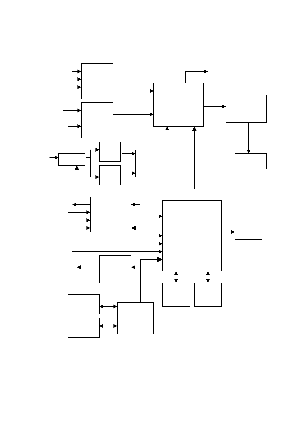
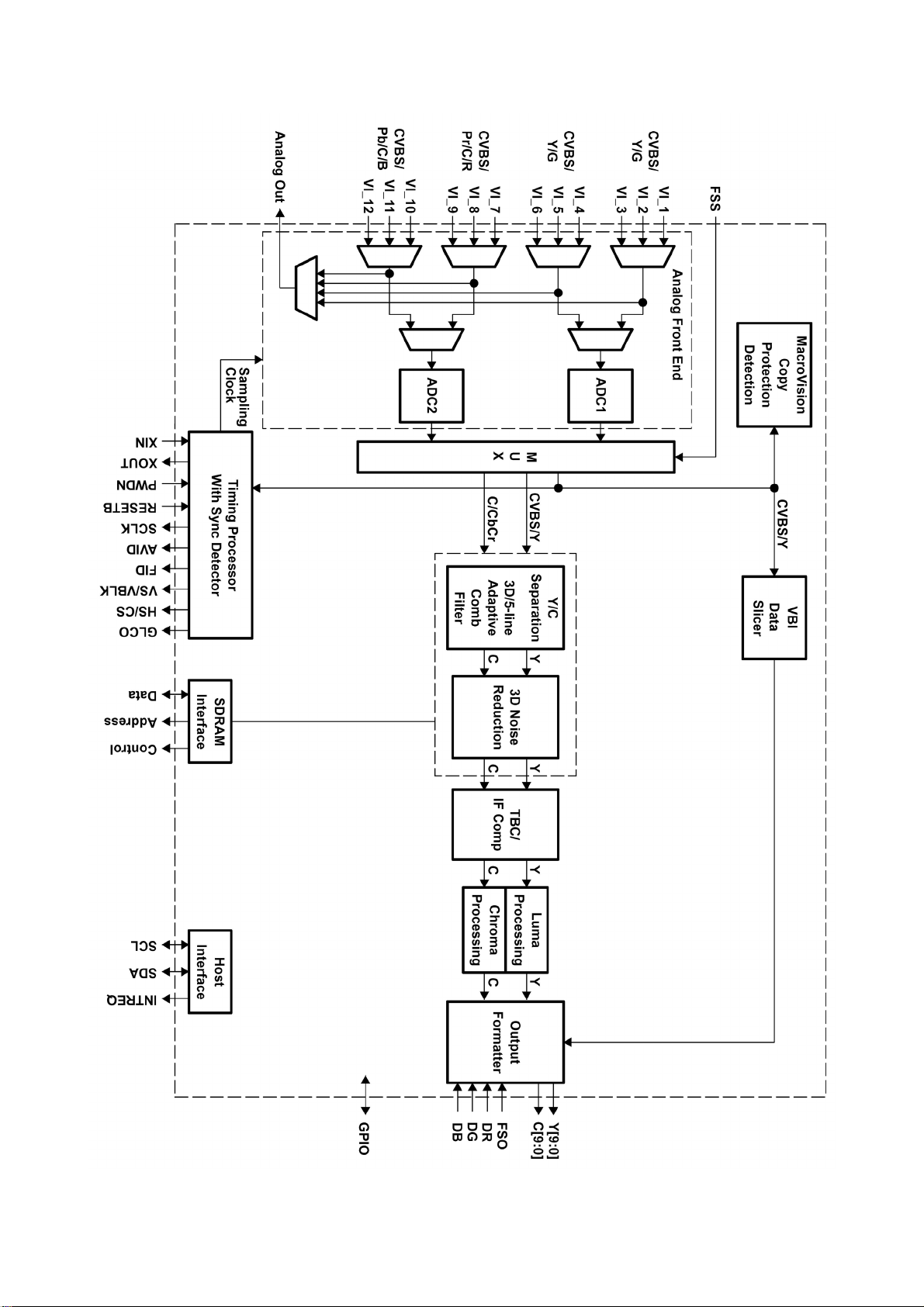
1. TVP5160
The TVP5160 device is a high quality, digital video decoder that digitizes and decodes all popular
baseand analog video formats into digital component video. The TVP5160 decoder supports the
A/D conversion of component YPbPr and RGB (SCART) signals, as well as the A/D conversion and
decoding of NTSC, PAL, and SECAM composite and S-Video into component YCbCr. Additionally,
component progressive signals can be digitized. The chip includes two 11-bit, 60-MSPS, A/D
converters (ADCs). Prior to each ADC, each analog channel contains an analog circuit, which
clamps the input to a reference voltage and applies a programmable gain and offset. A total of 12
video input terminals can be configured to a combination of YPbPr, RGB, CVBS, and S-Video video
inputs.
Progressive component signals are sampled at 2x clock frequency (54 MHz) and are then
decimated to the1x rate. In SCART mode the component inputs and the CVBS inputs are sampled
at 54 MHz alternately, then decimated to the 1x rate. Composite or S-Video signals are sampled at
4x the ITU-R BT.601 clock frequency (54 MHz), line-locked for correct pixel alignment, and are then
decimated to the 1x rate. CVBS decoding utilizes advanced 3D Y/C filtering and 2-dimensional
complementary 5-line adaptive comb filtering for both the luma and chroma data paths to reduce
both cross-luma and cross-chroma artifacts. 3D Y/C color separation may be used on both PAL and
NTSC video signals. A chroma trap filter is also available. On CVBS and Y/C inputs, the user can
control video characteristics such as hue, contrast, brightness, and saturation via an I2C host port
interface. Furthermore, luma peaking with programmable gain is included, as well as a patented
color transient improvement (CTI) circuit. Attenuation at higher frequencies or asymmetrical color
subcarrier sidebands are compensated using the IF compensation block. Frame adaptive noise
reduction may be applied to reduce temporal noise on CVBS, S-Video, or component inputs.
3D noise reduction and 3D Y/C separation may be used at the same time or independently.
The TVP5160 decoder utilizes Texas Instruments’ patented technology for locking to weak, noisy,
or unstable signals and can auto-detect between broadcast quality and VCR-style (nonstandard)
video sources.
The TVP5160 decoder generates synchronization, blanking, field, active video window, horizontal
and vertical syncs, clock, genlock (for downstream video encoder synchronization), host CPU
interrupt and programmable logic I/O signals, in addition to digital video outputs.
The TVP5160 decoder includes methods for advanced vertical blanking interval (VBI) data retrieval.
The VBI data processor (VDP) slices and performs error checking on teletext, closed caption, and
other VBI data. A built-in FIFO stores up to 11 lines of teletext data, and, with proper host port
synchronization, full-screen teletext retrieval is possible. The TVP5160 decoder can pass through
the output formatter 2x sampled raw Luma data for host-based VBI processing.
Digital RGB overlay can be synchronously switched with any video input, with all signals being
oversampled at 4x the pixel rate.
8
Page 11
9
Page 12
10
Page 13
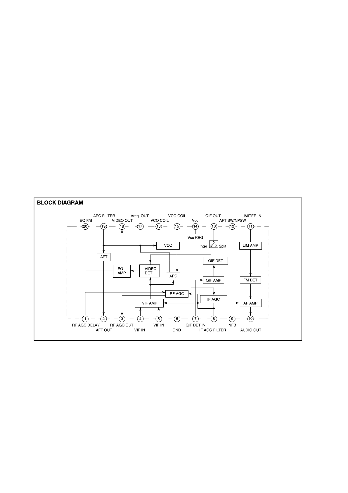
2. M52760SP
The M52760SP is IF signal-processing IC for VCRs and TVs. It enable the PLL detection system
despite size as small as that of conventional quasi-synchronous VIF/SIF detector, IF/RF AGC, SIF
limiter, FM detector and EQ AMP.
FEATURES
•Video detection output is 2VP-P. It has built-in EQ AMP.
•The package is a 20-pin shrink-DIP, suitable for space saving.
•The video detector uses PLL for full synchronous detection circuit. It produces excellent
characteristics of DG, DP; 920kHz beat, and cross color.
•Dynamic AGC realizes high-speed response with only single filter.
•Video IF and sound IF signal processings are separated from each other. VCO output is used to
obtain intercarrier. This PLL-SPLIT method provide good sound sensitivity and reduces buzz.
•As AFT output voltage uses the APC output voltage, VCO coil is not used.
•Audio FM demodulation uses PLL system, so it has wide frequency range with no external parts
and no adjustment.
•QIF AMP has a fixed gain, and good characteristic for NICAM.
2: AFT
3: AGC
4, 5: picture If input
7: sound IF input
13: SIF output
10: mono sound output
18: TV- VIDEO output
14, 17: +5V-1 power supply
11
Page 14

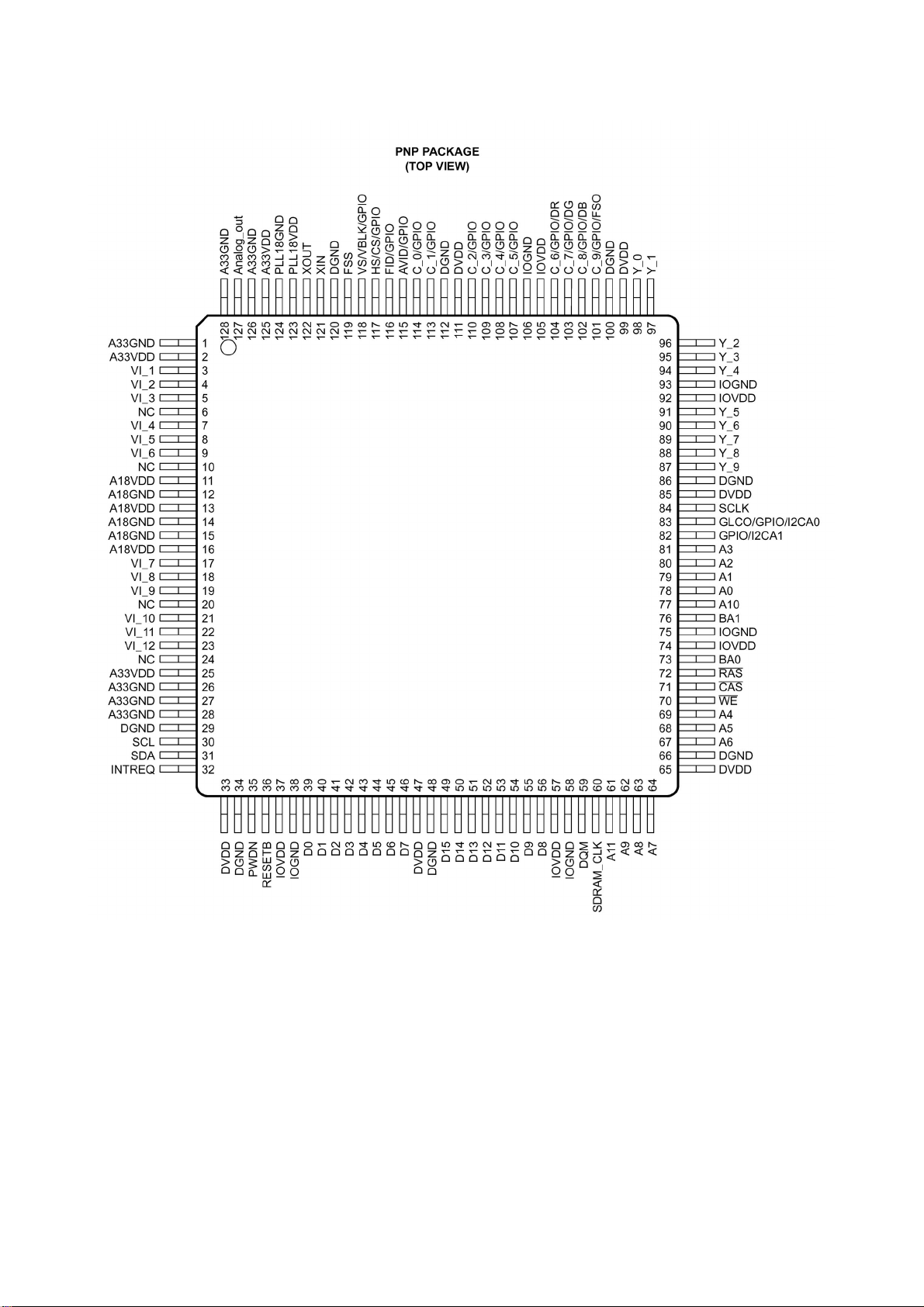
3. MST6151
pins function:
207, 208: HDMI-R input
2, 3: HDMI-G input
5, 6: HDMI-B input
8, 9: HDMI-CLK input
14: HDMI-SDA
15: HDMI-SCL
20, 21: VGA-B input
22: VGA-G input
23, 24: VGA-G input
25, 26: VGA-R input
18: VGA H-sync input
19: VGA V-sync input
27, 28: PB input
29, 30: Y input
31: HDMI-G input
32, 33: PR input
54-61: CCIR656 format signal input
53: CLK input
164-171, 174: 4 difference signal output
160, 161: 1 clock signal output
188-191: HDMI sound output
200: PWW (brightness control switch) output
72-75: BUS (parallel communication signal)
49, 131, 195: 1.8V power supply
4,17,12,109,204,66,102: 3.3V power supply
12
Page 15

4. MSP3425G
13
Page 16

5. TPA3008
FUNCTIONAL BLOCK DIAGRAM
1: MUTE
3: R input
5: L input
20, 17: L input
41, 44: R input
15, 23, 33, 39, and 47: +18V power supply
14
Page 17

Wiring diagram
A
Panel
CPU board (main board)
Power supply board
X903 X904
X7
X10
X1
X8
X3
X2
Voutboard
TV board
X6
X2
Speaker
15
Page 18

Trouble shooting
1. Fault clearance
Before servicing please check to find the possible causes of the troubles according to the table
below.
1.1 Antenna (signal):
Picture is out of focus or jumping Bad status in signal receiving
Poor signal
Check if there are failures with the electrical connector or
the antenna.
Check if the antenna is properly connected.
Fringe in picture Check if the antenna is correctly oriented.
Maybe there is electric wave reflected from hilltop or
building.
Picture is interfered by stripe shaped
bright spots
There appear streaks or light color
on the screen
1.2 TV set:
Symptoms Possible cause
Unable to switch the power on Check to see if the power plug has been inserted properly
No picture and sound Check to see if the power supply of liquid crystal TV has
Deterioration of color phase or color
tone
Screen position or size is not proper Check is the screen position and size is correctly set up.
Picture is twisted and deformed Check to see if the picture-frame ratio is properly set up.
Picture color changed or colorless Check the “Component” or “RGB” settings of the liquid
Possibly due to interference from automobile, train, high
voltage transmission line, neon lamp etc.
Maybe there is interference between antenna and power
supply line. Please try to separate them in a longer
distance.
Maybe the shielded-layer of signal wire is not connected
properly to the connector.
Check if interfered by other equipment and if interfered
possibly by the equipment like transmitting antenna,
non-professional radio station and cellular phone.
into the socket.
been switched on. (As can be indicated by the red LED at
the front of the TV set)
See if it’s receiving the signal that is transmitted from other
source than the station
Check if it’s connected to the wrong terminal or if the input
mode is correct.
Check if the signal cable connection between video
frequency source and the liquid crystal TV set is correct.
Check if all the picture setups have been corrected.
crystal TV set and make proper adjustment according to the
16
Page 19

signal types.
Picture too bright and there is
distortion in the brightest area
Picture is whitish or too bright in the
darkest area of the picture
No picture or signal produced from
the displayer if “XXX in search”
appears.
There appears an indication -
“outside the receivable scope)
Remote control cannot work
properly
No picture and sound, but only
hash.
Blur picture Check if the antenna cable is correctly connected.
No sound Check if the “mute” audio frequency setting is selected.
When playing VHS picture search
tape, there are lines at the top or
bottom of the picture.
Check if the contrast setting is too high.
Possibly the output quality of DVD broadcaster is set too
high.
It maybe also due to improper terminal connection of the
video frequency signal in a certain position of the system.
Check if the setting for the brightness is too high
Possibly the brightness grade of DVD player (broadcaster)
is set too high.
Check if the cable is disconnected.
Check if it’s connected to the proper terminal or if the input
mode is correct.
Check if the TV set can receive input signal. The signal is
not correctly identified and VGA format is beyond the
specified scope.
Check if the batteries are installed in the reverse order.
Check if the battery is effective.
Check the distance or angle from the monitor.
Check if there is any obstruct between the remote control
and the TV set.
Check if the remote control signal- receiving window is
exposed to strong fluorescence.
Check if the antenna cable is correctly connected, or if it
has received the video signal correctly.
Of if it has received the right video signal.
Check if the sound volume is set to minimum.
Make sure the earphone is not connected.
Check if the cable connection is loose.
When being played or in pause VHS picture search tape
sometimes can’t provide stable picture, which may lead to
incorrect display of the liquid crystal TV, In this case please
press “auto” key on the remote control so as to enable the
liquid crystal TV set to recheck the signal and then to
display correct picture signal
17
Page 20

2. Identification criteria for the bright spot and dark spot of the LCD screen
Category Criteria
One single
spot
Bright
spot
Dark
spots
Total defected point ≤8 ≤7 ≤5 ≤4 /
Two
neighboring
spots
Tot al N o . ≤5 ≤2 ≤5 ≤2 ≤3
One single
spot
Two
neighboring
spots
Tot al N o . ≤6 ≤7 ≤5 ≤4 ≤10
15" 20" 22" 30" 40" 15" 20" 22" 30" 40"
≤5 ≤2 ≤5 ≤2 ≤3
≤2 ≤1 ≤2 ≤1 ≤1
≤6 ≤7 ≤5 ≤4 ≤10
≤2 ≤2 ≤2 ≤1 ≤5
Notes:
1. Definition of defected point (bright spot, dark spot): It is identified as a defected point if its area
exceeds 1/2 of a single picture element (R, G, B).
2. Definition of bright spot: It is identified as a bright spot if it is bright in the state of dark field and its
bright size remains unchanged
3. Definition of dark spot: It is identified as a dark spot if it is dark in the state of white field and its
dark size remains unchanged
4. Definition of two neighboring points: Defects of a group of picture elements (RB, RG, GB).
Quantity allowed Distance between two spots
≥15mm
≥15mm
≥10mm ≥5mm
18
Page 21

3. Troubleshooting guide
k
f
p
n
3.1. No raster
Turn-on power supply, chec
if the red indicator is light in
the STANDBY?
no
Check if PIN8(5V) of CPU
board is normal?
no
Check STANDBY circuit o
ower supply board
Press POWER button in the
unit button and sensor control,
check the indicator.
Check if the PIN12 of X503 in
CPU board is high-level?
Check back light board
no
Replace N801
yes
red
blue
yes
no
Check if the PIN7 of X501 i
CPU board is high-level?
yes
Check power supply board
19
Page 22

3.2. Raster, but no picture
y
p
d
V
f
p
Check if the unit button
and remote control
operation?
yes
no
no
Replace CPU
board
Enter factory-menu,
initialization EEPROM,
then turn off the TV,
turn on again, displa
icture?
Adjust CPU boar
Does display OSD
menu in screen when
ress submenu?
yes
again
yes
Replace
TUNER1
yes
yes
Check if the all
channels have signal?
Which is no signal
Check if 1VPP signal
and noise wave of X2
(PIN 1) in the T
board?
no
no
of channels
TV
no
Check if output
IF signal o
TUNER1 (pin
11) is normal?
yes
Check N101
HDMI/VGA/YPRP
Replace
CPU board
20
Page 23

3.3.no sound
f
N
f
N
Check if PIN15, PIN30
and PIN38 voltage o
401 is normal?
Check power supply
no
yes
Check PIN26 and
PIN27 output wave o
801
no
Check PIN13 output
wave of N101
no
Check PIN5 wave of
Z102
no
Check PIN11 wave of
TUNER1
no
Replace TUNER1
yes
Replace N401
yes
Replace N801
yes
Replace N101
21
Page 24

AV OUT board
Page 25

key board
Page 26

POWER BOARD
667-L27U25-20
Page 27

IR board
Page 28

MCU
CPU board (page1 of 8)
Page 29

LVDS&BK
CPU board (page2 of 8)
Page 30

POWER
CPU board (page3 of 8)
Page 31

SDRAM
CPU board (page4 of 8)
Page 32

TVP5160
CPU board (page5 of 8)
Page 33

YPbPr&AUDIO SWITCH
CPU board (page6 of 8)
Page 34

CPU board (page7 of 8)
Page 35

CPU board (page8 of 8)
Page 36

video board (page1 of 2)
Page 37

video board (page1 of 2)
Page 38

APPENDIX-A: Main assembly 9227LU2614
NAME NO.
Video processing board
CPU board
Audio covert board
Key board
IR board
Power board
Remote control
Panel
6LU0154010
6LU0065610
6LU0081510
6LU0160510
6LU01609A0
6LU0082010
6010R03202
5203275501
MAIN COMPONENT AND IT'S NO.
N101
N801
N401
N101
N601
NA01
N801
RC-R32M-0B
V270B1-L01
M52760 (5265276001)
MSP3425G (5273425001)
TPA3008D2 (5273008001)
MST6151DA (5276151001)
TVP5160 (5275160001)
CS4340 (5274340001)
MM502 (5270502001)
Page 39

APPENDIX: Exploded view (LC-27X26)
Page 40

PART LIST OF EXPLODED VIEW (LC-27X26)
NO. PART NO. DESCRIPTION
1 5QX26W009D Front cabinet
2 Screen
3 58A0039100 LCD screen frame (top)
4 58A003930A LCD screen frame upright1
5 58A0039500 LCD screen connection bracket1
6 574018901B Power board frame
7 5740188010 Main board frame
8 Power board assy
9 CPU board assy
10 58A0039700 Wall mount connection piece
11 5830D9681B AV baffle (left)
12 5830D96910 AV baffle (right)
13 Key board assy
14 5HX26WH01C Back cabinet
15 5830098110 Back cabinet cover (right)
16 5830098010 Back cabinet cover (left)
17 5830098210 Rotor cover
18 6151067520 Stand assy
19 6170575000 Speaker assy
20 Analog board assy
21 trans-connect board assy
22 5810046800 Connecting piece of speaker box
23 IR receice board
24 5830097010 AV baffle (bottom )
25 Active Decorative piece
26 58A0039200 LCD screen frame(bottom )
27 58A0039400 LCD screen frame upright2
28 58A0039600 LCD screen connection bracket2
29 58B0A24110 Main switch bracket
Page 41

9227LU2614
Ver.1.0
 Loading...