

Page 1
LCD-TV
LC27M6S
Page 2

CONTENTS
SAFETY INSTRUCTIONS………………………………………………………………………1
INSTRUCTIONS ON ADJUSTING AND TEST ING…………………………………………….3
TROUBLE SHOOTING……………………………………………………………………………8
METHOD OF SOFTWARE UPGRADING……………………………………………………10
BASIC WORKING PRINCIPLE…………………………………………………………………10
BLOCK DIAGRAM…………………………………………………………………………...12
MAIN IC BLOCK DIAGRAM…………………………………………………………………..13
WIRING DIAGRAM………………………………………………………………………….17
SERIAL NO. OF PARTS…………………………………………………………………………18
TROUBLESHOOTING GUIDE………………………………………………………………….19
SCHEMATIC DIAGRAM………………………………………………………………….29
Page 3

Attention: This service manual is only for service personnel to take reference with. Before servicing
please read the following points carefully.
Safety instructions
1 Instructions
1.1 Be sure to switch off the power supply before replacing or welding any components or
inserting/plugging in connection wire
1.2 Anti static measures to be taken (throughout the entire production process!):
1.2.1 Do not touch here and there by hand at will;
1.2.2 Be sure to use anti static electric iron;
1.2.3 It’s a must for the welder to wear anti static gloves.
1.3 Please refer to the detailed list before replacing components that have special safety requirements.
Do not change the specs and type at will.
2 Points for attention in servicing of LCD
2.1 Screens are different from one model to another and therefore not interchangeable. Be sure to use
the screen of the original model for replacement.
2.2 The operation voltage of LCD screen is 700-825V. Be sure to take proper measures in protecting
yourself and the machine when testing the system in the course of normal operation or right after
the power is switched off. Please do not touch the circuit or the metal part of the module that is in
operation mode.
Relevant operation is possible only one minute after the power is switched off.
2.3 Do not use any adapter that is not identical with the TV set. Otherwise it will cause fire or damage to
the set.
2.4 Never operate the set or do any installation work in bad environment such as wet bathroom, laundry,
kitchen,or nearby fire source, heating equipment and devices or exposure to sunlight etc. Otherwise
bad effect will result.
2.5 If any foreign substance such as water, liquid, metal slices or other matters happens to fall into the
module, be sure to cut the power off immediately and do not move anything on the module lest it
should cause fire or electric shock due to contact with the high voltage or short circuit.
2.6 Should there be smoke, abnormal smell or sound from the module, please shut the power off at once.
Likewise, if the screen is not working after the power is on or in the course of operation, the power
must be cut off immediately and no more operation is allowed under the same condition.
2.7 Do not pull out or plug in the connection wire when the module is in operation or just after the power
is off because in this case relatively high voltage still remains in the capacitor of the driving
circuit.Please wait at least one minute before the pulling out or plugging in the connection wire.
2.8 When operating or installing LCD please don’t subject the LCD components to bending, twisting or
extrusion, collision lest mishap should result.
2.9 As most of the circuitry in LCD TV set is composed of CMOS integrated circuits, it’s necessary to pay
attention to anti statics. Before servicing LCD TV make sure to take anti static measure and ensure
full grounding for all the parts that have to be grounded.
1
Page 4
2.10 There are lots of connection wires between parts behind the LCD screen. When servicing or
moving the set please take care not to touch or scratch them. Once they are damaged the screen
would be unable to work and no way to get it repaired.
2.11 Special care must be taken in transporting or handling it. Exquisite shock vibration may lead to
breakage of screen glass or damage to driving circuit.
Therefore it must be packed in a strong case before the transportation or handling.
2.12 For the storage make sure to put it in a place where the environment can be controlled so as to
prevent the temperature and humidity from exceeding the limits as specified in the manual. For
prolonged storage, it is necessary to house it in an anti-moisture bag and put them altogether in one
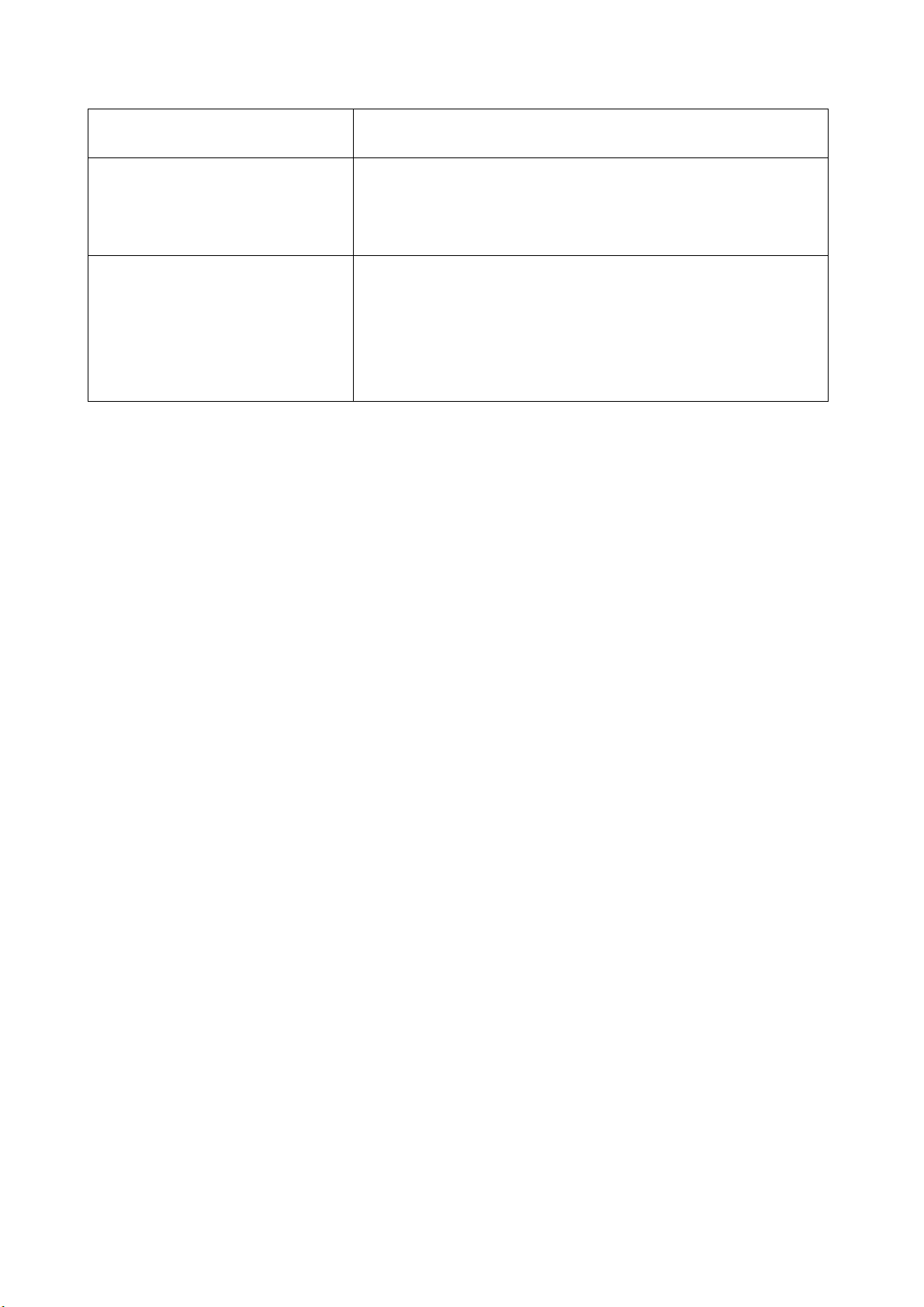
place. The ambient conditions are tabulated as follows:
Temperature Scope for operation
Scope for storage
humidity Scope for operation
Scope for storage
2.13 Display of a fixed picture for a long time may result in appearance of picture residue on the screen,
as commmonly called “ghost shadow”. The extent of the residual picture varies with the maker of
LCD screen. This phenonmenon doesn’t represent failure. This “ghost shadow” may remain in the
picture for a period of time (several minutes).But when operating it please avoid displaying still
picture in high brightness for a long time.
0—+50 C
-20—+60 C
20%—85%
10%—90%
3. Points for attention during installation
3.1 The front panel of LCD screen is of glass. Wheng installing it please make sure to put it in place.
3.2 For service or instatallation it’s necessary to use specified screw lest it should damage the screen.
3.3 Be sure to take anti dust measures. Any foreign substance that happens to fall down between the
screen and the glass will affect the receiving and viewing effect
3.4 When dismantling or mounting the protective partition plate that is used for anti vibration and
insulation please take care to keep it in intactness so as to avoid hidden trouble.
3.5 Be sure to protect the cabinet from damage or scratch during service, dismantling or mounting.
2
Page 5
Instructions on adjusting and testing
1. Debugging equipment
PM5515(Video signal generator), PM54200(SCART signal generator), VG-848(signal generator of
YUV,VGA,DVI), and CA210(White balancer)
2. Process of debugging
See Fig.1.
Connect to central signal source, check various TV functions (station skipping, analog control
Input AV/SVIDEO,SCART, and check for various functions of each terminal
Input high definition signal (mode), check on the various functions of the terminal
Input signal of VGA and DVI (1 format) and check if display is normal in PC state and check
3. Debugging for complete set
Connect the data processing board, sound processing board, TV processing board, keyboard,
remote control receiving board and upgrading processing board according to wiring diagram
203-L27M60-02JL. Switch it on and then observe if the display is normal.
How to use the factory menu:First press”POWER”and press “video” immediately after to enter
the factory menu. Press”S.M” and it is possible to change an adjustment page of factory menu. Press
keys “CH+”and”CH-” it is possible to move the cursor up and down on a certain adjustment page. When
the cursor is moved to a certain adjustment item, press “VOL-”and “VOL+” keys and then it is possible to
carry out the adjustment for the item. Press”MENU” and exit from the factory menu. Before switching off
the TV set, press”S.M” and it is possible to reenter the factory menu(This state is called factory state).
Check HDCPEEPROM, DDC, FLASH, PAL to see if they are flash written.
In-production data processing board and analog board
Check the data processing board and analog board
Combined adjustment for the general assembly
etc.), check if output of earphone and speaker is normal.
on various functions, (analog control), line/field center etc.
Setting for ex-works
Check accessories and then packing
Fig.1 Debuggingprocess
3
Page 6

When the machine is switched off it is possible to exit from the factory state.
3.1. EEPROM Initialization
Enter the first page of the factory menu, select EEPROM Erase and then press”ENTER” key. Switch
the TV set off and restart the set. Then it’s ready for initialization.
Note: For the restart it t akes relatively longer ti me t o show blue screen!
3.2. Check on white balance
3.2.1. White balance for YpbPr channel
Connect the signal of 480I(968 mode)in VG-848 to YpbPr port. Input the signal of gray degree 16
(921 graph spectrum). Fix the R Gain, G Gain and B Gain of the White Balance Adjust as 80H, 80H, and
80H.Set the R Offset, G offset and B offset of the 9883 Adjust items so that the color coordinates of the
th
step from the left are 254 and 250 and the brightness is 3.5nit. Check if the color coordinates of the
4
th
step (4th step from the right) are 267 and 267 and if the brightness is 400 nit. If not, recheck the
13
th
brightness and color coordinates of the 4
step and repeatedly adjust R Offset, G offset, B offset until the
two gray degrees are both adjusted to the specified values.
Separately input the signals of other formats in Table 1. Repeat the operations above so that the
white balance is up to the requirement as above.
4. Performance check
4.1. TV function
Connect RF port to the central signal source. First enter the menu for selected items. Set the
category of country. Then enter edit menu → auto station searching and check if there is skipped
stations. Check for manual station searching to see if fine adjustment is normal. Check if the output of
earphone and loudspeaker is normal and if the image is normal. Switch on PIP and POP(multi
pictures),connect earphone wire and check if the display and sound are normal.
4.2. AV/S-Video port
Separately input the signals from the terminals of AV/S and check if the display and sound are
normal. Switch on PIP and POP(multi pictures),connect earphone wire and check if the display and
sound are normal.
4.3. SCART port(Note: When checking SCART port,the mode displayed on the menu for selection items
should be Auto)
4.3.1. Check of the special function of SCART INPUT
4.3.1.1. Function of SCART1
a).When the TV set is switched on, connect SCART1 to the signal generator(PM54200).Then the
TV set should be automatically switched over to the state of Scart1.
b).SCART signal generator sends out CVBS signal(color stripe + multi-wave group).Observe if the
image and sound of the set are normal. Change the display format (16:9 and 4:3) of the image output
from the signal source. Check if the TV set can automatically identify it. When SCART signal is changed
into that of RGB,observe if the image and sound of the set are normal. Change the display format (16:9
and 4:3) of the image output from the signal source. Check if the TV set can automatically identify it.
Switch on PIP,connect the earphone and check if the display and sound are normal.
4.3.1.2. Function of SCART2
a). When the TV set is switched on, connect SCART2 to the signal generator(PM54200).Then the
TV set should be automatically switched over to the state of Scart2.
b).SCART signal generator sends out CVBS signal(color stripe + multi-wave group).Observe if the
image and sound of the set are normal. Change the display format (16:9 and 4:3) of the image output
from the signal source. Check if the TV set can automatically identify it. Now the normal screen display
4
Page 7
should be Scart2 AV and SCART signal is changed into that of Y/C. Switch the channel over to SCART 2
Y/C and observe if the picture and sound are normal. Change the display format (16:9 and 4:3) of the
image output from the signal source. Check if the TV set can automatically identify it. Switch PIP
on,connect the earphone and check if the display and sound are normal.
4.3.2. Check of special function of SCART OUTPUT
4.3.2.1. Function of SCART1
In the state of TV input the signal. Connect SCART1 port to the TV set for monitor purpose. Change
the TV channel and see if the output signal from SCART1 is that of TV and see if the picture and sound
of the TV for monitor purpose are normal. Change the TV channel and now the output signal from
SCART1 should be that of TV and should not vary with the change of channel.
4.3.2.2. Function of SCART2
Separately input the signal in the state of TV/AV/S. Connect the SCART2 port to the TV set for
monitor purpose. Change the TV channel in the state of TV/AV/S and see if the output signal from
SCART2 is that of the present and see if the picture and sound of the TV for monitor purpose are normal.
4.4. Port of YPbPr/YCbCr
Input the signal of YUV(VG-848 signal generator). Separately input the various formats of YUV
signals as in Table 1. Check if the display and sound are normal. If there are deviations for the line and
field values on the picture, press Auto Sync on the Screen menu and make calibration. If the picture
shows slight interference, adjust the Fine Tune of the Screen menu for calibration. Switch PIP
on,connect the earphone and check if the display and sound are normal.
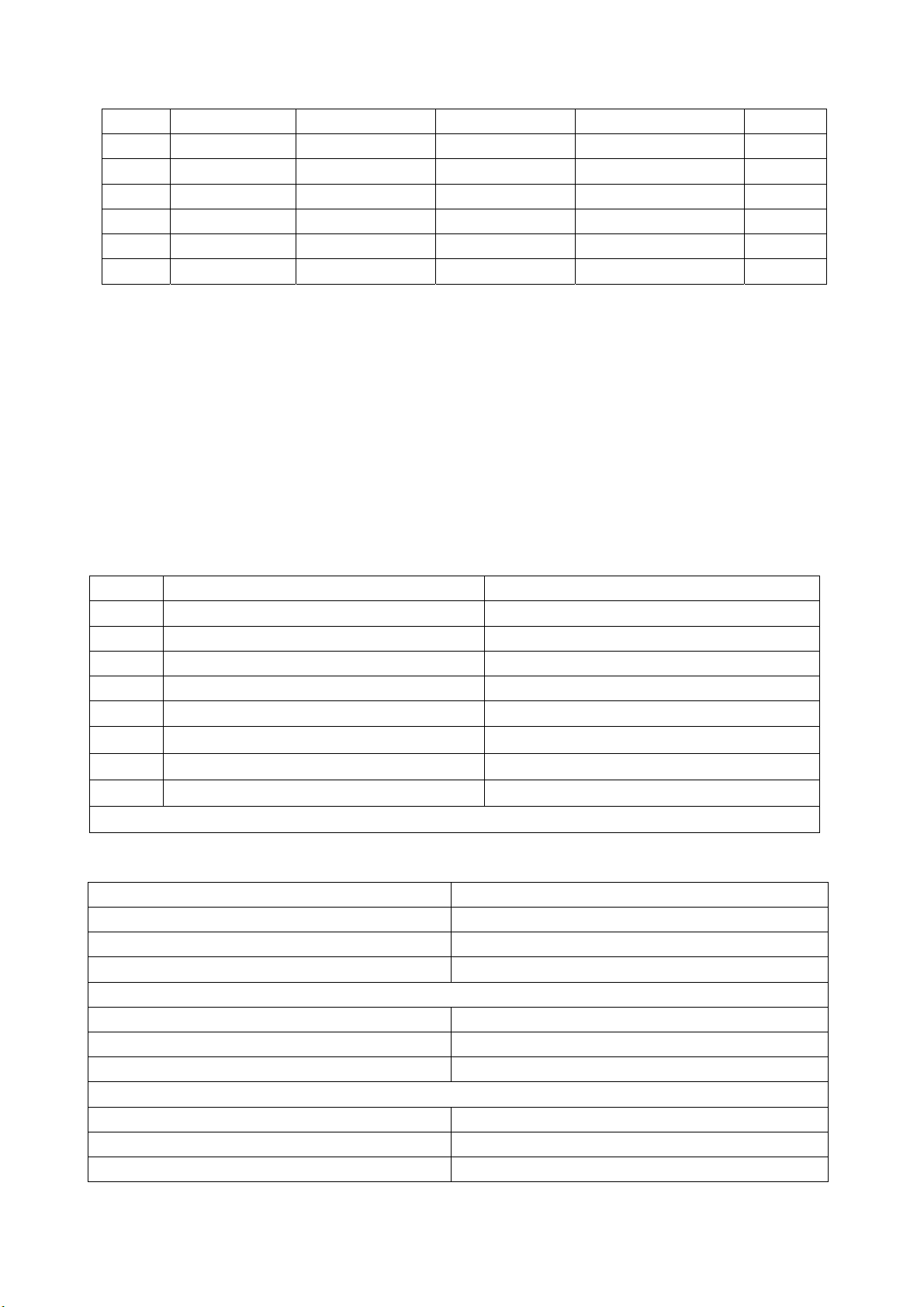
Table 1 Signal Formats YUV Receives
symbol H-frequency(kHz) V-frequency(Hz) signal
1 15.734 59.94 SDTV 480i
2 31.469 59.94 HDTV 480p
4 44.955 59.94 HDTV 720p
6 33.716 59.94 HDTV 1080i
7 15.625 50 SDTV 576i
8 31.25 50 SDTV 576p
9 33.75 50 HDTV 1080i
10 37.50 50 HDTV 720p
4.5. VGA Port
Input the VGA signal(VG-848 signal generator). Separately input the various formats of YUV signals
as in Table 2. Check if the display and sound are normal. If there are deviations for the line and field
values on the picture, press Auto Sync on the Screen menu and make calibration. If the picture shows
slight interference, adjust the Fine Tune of the Screen menu for calibration. Switch PIP on,connect the
earphone and check if the display and sound are normal.
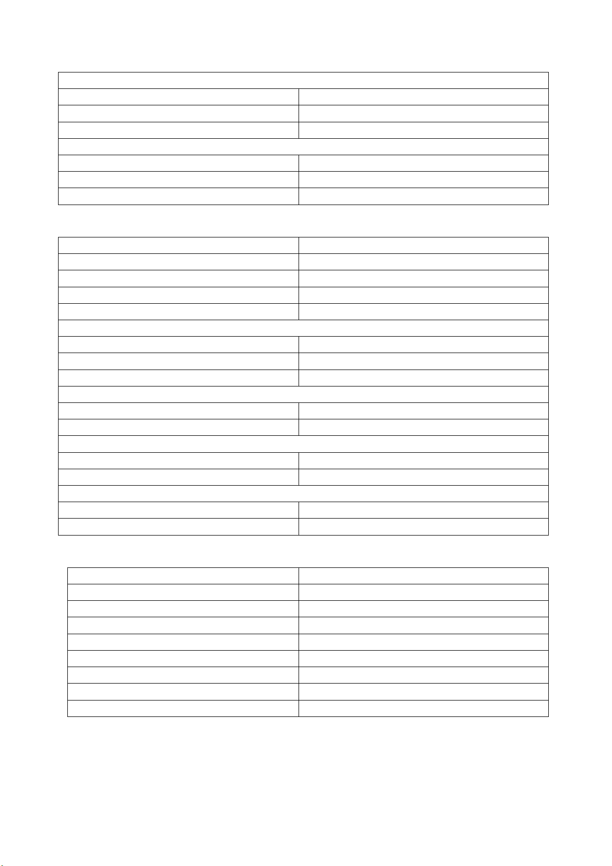
Table 2 Signal Formats VGA Receives
symbol resolution H-frequency(Hz) V-frequency(Hz) Dot frequency(MHz) remarks
1 720x400 31.469 70.086 28.322 IBM
2 640x480 31.469 59.94 25.175 IBM
3 640x480 37.861 72.809 31.5 VESA
4 640x480 37.5 75.0 31.5 VESA
5 640x480 43.269 85.008 36 VESA
6 800x600 35.156 56.25 36 VESA
5
Page 8
7 800x600 37.879 60.317 40 VESA
8 800x600 48.077 72.188 50 VESA
9 800x600 46.875 75.0 49.5 VESA
10 800x600 53.674 85.061 56.25 VESA
11 1024x768 48.363 60.004 65 VESA
12 1024x768 56.476 70.069 75 VESA
13 1024x768 60.023 75.029 78.75 VESA
4.6. DVI Port
In addition to the signal formats as listed in Table 2, DVI can receive the following three high
definition signal formats -- 576P, 720P/60 Hz and 1080I/60 Hz. Input the DVI signal(VG-848 signal
generator). Separately input the signals of the various DVI formats as listed above. Check if the display
and sound are normal.
If there are deviations for the line and field values on the picture, press Auto Sync on the Screen
menu and make calibration. Switch PIP on,connect the earphone and check if the display and sound are
normal.
4.7. For the ex-works settings please see Tables 3-8. (Ex-works setting values have been normally
initialized by the software. The only thing for the factory to do is to proof read the values.
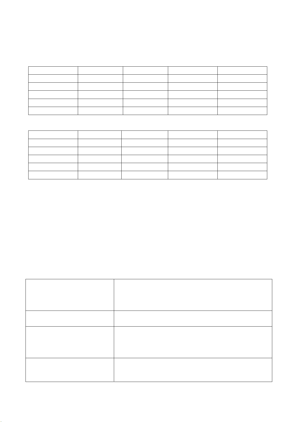
Table 3 Setting of Factory Option Menu Page
symbol item ex-works settings
EEPROM Erase Off
1 Backlight Adjustable Off
2 Back Light 99
3 Menu Timeout 15
4 Blank switch enable Off
5 ShowLogo On
6 Auto Channel Lable On
Disable SRS active Stereo
Note: The last 5 items of Table 3 should be designed according to the customer’s request.
Table 4 Setting of Video Min/Max Page
item ex-works settings
Bright Min C0H
Bright Middle 00H
Bright Max 10H
Contrast Min 10H
Contrast Middle 20H
Contrast Max 28H
Sharpness Min 00H
Sharpness Middle 10H
Sharpness Max 1FH
6
Page 9
Color Min 00H
Color Middle 32H
Color Max 63H
Hue Min CEH
Hue Middle 00H
Hue Max 32H
Table 5 Setting of Factory Audio Setting Page
item ex-works settings
Volume Min 37H
Volume 30 63H
Volume 50 70H
Volume Max 76H
Prescale Scart 3FH
Prescale FM/AM 1FH
Prescale Nicam 40H
Scart1 Volume 20H
Scart2 Volume 20H
D/K select HDEV3 Off
Equalizer Bands Max 60H
Spatial Mode Off
AVC Off
Table 6 White Balance Adjust Setting Page
item ex-works settings
R Offset 1CH
G Offset 00H
B Offset 25H
R Gain F0H
G Gain F0H
B Gain F0H
Brightness 50
Contrast 50
Note:9883 Adjust is only for adjustment of YPBPR white balance, so different models and units may
have different values.
Set 9883 Registers are used for design and adjustment, so they can’t be used to memory things
while changing the values.
7
Page 10
In the state of factory,it is possible to change setting values for picture and sound in various factory
modes. Otherwise any equilibrium values of picture and sound different in the other states are
considered the setting of Custom.
Table 7 Setting of Picture Analog Value
Vivid Standard Mild Custom
Contrast 80 70 50 50
Brightness 50 45 40 50
Color 50 45 40 50
Hue 00 00 00 00
Sharpness 50 50 50 50
Table 8 Setting of Sound Equilibrium Value
Live Pop Rock Custom
120 Hz 50 50 65 50
500 Hz 50 50 55 50
1.5 kHz 50 60 55 50
5 kHz 80 70 55 50
10 kHz 85 70 55 50
Ex-works settings for User Menu are as follows:
1) The channel is selected as that of the present TV;
2) Under video menu,Mode:Standard, NR:Auto;
3) Under audio menu,Volume:20,Balance:00,Equalizer:Custom,SRS Mode:Auto,HP Volume:20;
4) Under edit menu,Color System:Auto, Sound System:I;
5) Under the menu of selection items: Default Zoom:Auto, Child Lock:Off, Menu Language:English,
Country:UK, WSS:OFF, Blue Screen:On.
Note: The forth item and the fifth item should be designed according to the customer’s request.
Trouble shooting
Before servicing please check to find the possible causes of the troubles according to the table below.
1.Antenna:
Picture is out of focus or jumping Bad status in signal receiving
Maybe broadcast signal itself is not good
Check if the outdoor antenna is disconnected.
Check if the antenna is correctly oriented.
Fringe in picture Check if the antenna is correctly oriented.
Maybe there is electric wave reflected from hilltop or building.
Picture is interfered by stripe
shaped bright spots
There appear streaks or light color
on the screen
Possibly due to interference from automobile, train, high
voltage transmission line, neon lamp etc.
Maybe there is interference between antenna and power
supply line. Please try to separate them in a longer distance.
Check if interfered by other equipment and if interfered
possibly by the equipment like transmitting antenna, non
professional radio station and cellular phone.
8
Page 11
2.TV set:
Symptoms Possible cause
Unable to switch the power on Check to see if the power plug has been inserted properly into
the socket.
No picture and sound Check to see if the power supply of liquid crystal TV has been
switched on. (as can be indicated by the red LED at the front
of the TV set)
See if it’s receiving the signal that is transmitted from other
source than the station
Check if it’s connected to the wrong terminal or if the input
mode is correct.
Check if the signal cable connection between video frequency
source and the liquid crystal TV set is correct.
Deterioration of color phase or color
tone
Screen position or size is not proper Check is the screen position and size is correctly set up.
Picture is twisted and deformed Check to see if the picture-frame ratio is properly set up.
Picture color changed or colorless Check the “Component” or”RGB”settings of the liquid crystal
Picture too bright and there is
distortion in the brightest area
Picture is whitish or too bright in the
darkest area of the picture
No picture or signal produced from
the displayer if “XXX in
search”appears.
There appears an indication -
“outside the receivable scope)
Remote control cannot work
properly
No picture and sound, but only
hash.
Check if all the picture setups have been corrected.
TV set and make proper adjustment according to the signal
types.
Check if the contrast setting is too high.
Possibly the output quality of DVD broadcaster is set too high.
It maybe also due to improper terminal connection of the video
frequency signal in a certain position of the system.
Check if the setting for the brightness is too high
Possibly the brightness grade of DVD player(broadcaster)is
set too high.
Check if the cable is disconnected.
Check if it’s connected to the proper terminal or if the input
mode is correct.
Check if the TV set can receive input signal. The signal is not
correctly identified and VGA format is beyond the specified
scope.
Check if the batteries are installed in the reverse order.
Check if the battery is effective.
Check the distance or angle from the monitor.
Check if there is any obstruct between the remote control and
the TV set.
Check if the remote control signal- receiving window is
exposed to strong fluorescence.
Check if the antenna cable is correctly connected, or if it has
received the video signal correctly.
9
Page 12
Blur picture Check if the antenna cable is correctly connected.
Of if it has received the right video signal.
No sound Check if the “mute” audio frequency setting is selected.
Check if the sound volume is set to minimum.
Make sure the earphone is not connected.
Check if the cable connection is loose.
When playing VHS picture search
tape, there are lines at the top or
bottom of the picture.
When being played or in pause VHS picture search tape
sometimes can’t provide stable picture, which may lead to
incorrect display of the liquid crystal TVIn this case please
press “auto” key on the remote control so as to enable the
liquid crystal TV set to recheck the signal and then to
display correct picture signal
Method of software upgr adi ng
1.guidance for software installation
open the compressed files to obtain the “LoadDriver”, running the “IAPWriter.exe” and soon it will
enter into IAP program.
2.TV enter into IAP state(automatic software upgrading)
one method: press constantly the “vol –” button, turn on
another method: enter into the factory menu to select the “IAP” item, press the “enter” button
3.connect the “IICtools” of computer with the upgrading interface of TV.
4.running “ IAPWriter ” to enter into the upgrading state(if there are failure between the computer and
TV’s IIC communication, the indication that can’t enter into the next step will appear. you need to check
the wiring at this moment.
5.after selecting “files” menu and obtaining the software which requires upgraded, selecting the “Device”
menu: “write”→ “device”, until the indication of “success” appears at the down-left corner, turn off the
power, unplug the tool and turn on the TV again.
Note: the upgrading process maybe appears unstable because of the upgrading software, but the
software can download and write again automatic. if download and write repeated many times, please
turn off the TV and enter into IAP again, upgrade again.
Basic Working Principle
1. Analog signal flow process:
The signal received by antenna is fed into an integrated tuner (including high frequency and
medium amplification circuit). The tuner is controlled by the instructions (SDA, SCL) of MCU
N501(SDA5550), selects proper channels and conducts the right switching over of modes and outputs
video signal 2Vpp and audio signal 1Vpp after high and medium amplification and decoding.
Audio signal including SCART1,2 sound, AV sound as well as the YPbPr,DVI,D-SUB sound
signal switched over through N704 HEF4052BT (sound change-over switch), and Scart audio input
signal] is fed into N201 (MPS3410 sound processing and volume control)for the switch-over of audio
signal. The selected audio signal is fed, separately from left and right sound channels, into SRS
IC(M62494 virtual surrounding sound processing) N203, where it is subject to virtual surrounding sound
processing. The processed audio signal is fed, separately from left and right sound channels, into the
digital sound power amplifier N213/N214(MPS7720) for amplification and then further fed into
loudspeaker (in the future it may be changed into sound box for the improvement of sound quality) for
10
Page 13

sound reproduction. M62494 is a virtual surrounding sound processing IC, which is subject to the control
of I/O port (77/78Pin) of N201 MPS3410.
The video signal output from the tuner, AV signal and Svideo signal, after matching with resistor,
directly enter, respectively from its own channel, into the main decoder IC N101(PanelTv-Svp), where
they are subject to video switch-over, A/D conversion, digital decoding, image zooming and OSD
superposition. Then they are output in electric level TTL to N601 DS90C383 (LVDS transmitting IC) for
driving the crystal display screen.
The Scart1 video signal and RGB signal, after matching with resistor, enter into the decoder IC
N401 (VPC3230 digital decoder), where they are subject to A/D conversion, and digital decoding. Then
they are fed in digital format into PanelTv-Svp for image zooming and OSD superimposition. Afterwards
they are further fed, in electric level TTL, into N601 DS90C383(LVDS IC) for driving the liquid crystal
display screen.
The Scart2 video signal and Y/C signal, after matching with resistor, enter into the decoder IC N401
(VPC3230 digital decoder), where they are subject to A/D conversion, and digital decoding. Then they
are fed in digital format (IUT656) into PanelTv-Svp for image zooming and OSD superimposition.
Afterwards they are further fed, in electric level TTL, into N601 DS90C383 (LVDS IC) for driving the
liquid crystal display screen.
For the specific circuit type and internal block diagram, please see the attached Fig.
2. Digital signal fl ow process:
(For the time being we call D-SUB, YpbPr signal also as digital signal. But in fact the two signals are
analog ones in terms of transmission and are only in digital format after conversion in ADC ) D-Sub
signal and YpbPr signal are, after matching with resister, fed into N703 video switch
(SN74CBT3257CDR). After switching over, the selected signal is fed into ADC N201 MST9883 for A/D
conversion. Then it is output in digital format of (24 digits RGB signal) to PanelTv-Svp PIP channel.
Through image zooming and OSD superimposition, it is then output, in electric level TTL for driving
LVDS liquid crystal display screen.
DVI signal is received through DVI receiving CMOS chip N761(TFP501DVI receiving chip
Has HDCP function). Then the received signal is output through DVI chip in digital format into
PanelTv-Svp PIP channel. After image zooming and OSD superimposition, it is output in electric level
TTL for driving LVDS liquid crystal display screen.
3. Realization of TELETEXT functi on
To realize the TELETEXT function of the main channel, this TV set adopts MCU
N501(SDA5550),SDA5550 of MICRONAS, which is both MCU and TELETEXT decoder. This set can
realize this function by two ways. One is that the radio frequency, after being decoded in SDA5550,
through parallel interfaced bus line, realizes the TELETEXT function in the form of OSD. The advantage
in this way is the result is relatively good and the characters/symbols are stable; the disadvantage is that
it is relatively slow for the TELETEXT function to appear through OSD. The other way is that the radio
frequency is decoded in SDA5550 into RGB signal, which is subject to A/D conversion in IC
N401(VPC3230 digital decoder) and then it is fed in digital format into PanelTv-Svp for the realization
of TELETEXT function. The advantage in this way is the speed the teletext comes out is faster and the
disadvantage is due to the fact that it is fed, in analog RGB form, into VPC3230 and goes through it, the
analog signal is easily subject to outside interference and thus the stability of characters/symbols is not
so good as the previous way (through OSD). We have chosen the first way. which in turn it is relatively
slow for the TELETEXT function to appear through OSD.
11
Page 14
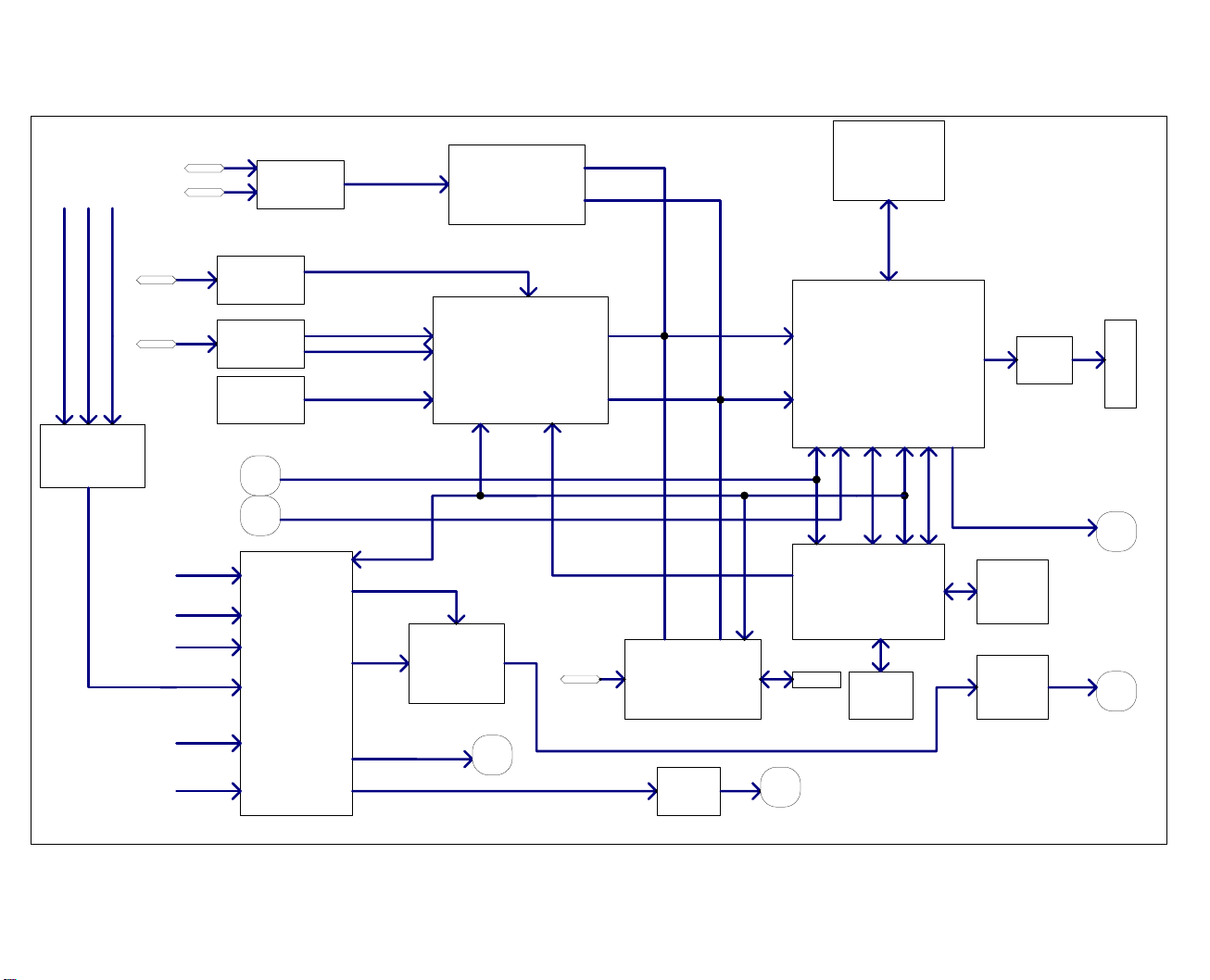
4.BLOCK DIAGRAM
YPBPR
PC
RGB AUDIO
YPBPR AUDIO
DVI AUDIO
AV OUT
PI5V330
SCART2
RGB/YUV
Y/VIN1 C
MST9883
24-BIT Data
HS,VS,CLK
2X4MX32
SDRAM
TV OUT
TC4052
AV1/YC AUDIO
SCART1 AUDIO
SCART2 AUDIO
AUDIO
MP AUDIO
PIP AUDIO
SCART1
TUNER2
TUNER1(CVBS1)
Y/CVBS3 C
MSP34X0
SCART RGB
VIN3
VIN2
SRS STEREO/MONO
AUDIO OUT
VPC3230
M62494
8-bit Data
HS,VS,CLK
Teletext RGB FB
DVI
TMDS:TFP501
TLE2142
EARPHONE
Panel-SVP
BGA320
I2C
AD[0-7]
SDA5550M
AT24C08
AT24LC 32
24Bit DIGITAL OUT
DS90C383
Panel
FB
CVBS_OUT
FLASH
MP7720
SPEAK
12
Page 15

5. Introduction to main IC and principle block diagram
a). Sound processing IC(MSP3410)
Audio signal is fed directly into audio processor N201 MSP3410 whereas two-way tuner sends
intermediate frequency signal SIF of its second sound to N201 for processing (used for decoding of
stereo or automatic sound volume control. N201 is equipped with audio channel changeover switch.
The audio input VGA/DVI/YPrPb of the main board is subject to selection and switch over in
N704(HEF4052BT) and then sent to N201 together with the audio signal of TV and AV. The
selected audio signal is divided into several portions. One portion is sent separately through left and
right channels, after being subject to the control of volume and pitch(alt/bourdon), into SRS
IC(M62494 virtual surround sound processor) N203 for virtual surround sound processing. The
processed audio signal is then fed separately through left and right sound channels into digital
sound power amplifier N213/N214(MPS7720) for amplification, and then further fed into the
loudspeaker (In the future it may be changed into sound box for improved sound quality) for the
reproduction of sound. Another portion is fed separately through left and right sound channels into
the earphone power amplifier N212(TLE2142). After amplification there it is output to earphone jack
for listening to. The volume in controlled through I2C bus line by N201. The other two portions
are output, separately used as accompanying sound of TV out and AV out, through the port SCART
of the video board.
The block diagram of MSP3410 is shown in the Fig. below:
The main pins of MSP3410 in this TV model are described as follows:
2, 3:SCL and SDA, for the control of the operations of IC;
27, 28:output to the left and right channels of sound power amplifier;
24, 25: for left and right channels of earphone sound;
36, 37:AV OUT left and right sound channels;
33, 34:TV OUT left and right sound channels;
47, 48:fed from the main board to left and right sound channels;
50, 51:left and right channels of SCART2 sound;
53, 54:left and right channels of SCART1 sound;
13
Page 16

56, 57:left and right channels of AV IN sound;
67, 69:SIF input of TV for main and sub channels;
59:MONO input of TV for sub channel
Sound power amplifier MPS7720 is a highly efficient Type D power amplifier of mono channel input and
output. The output power can be as high as 10W under the circumstance that there is no radiator. It has
also the function of silencing abnormal sound.
b). Sub channel and SCART audio signal decoding IC(VPC3230)
The block diagram of VPC3230 is shown below:
The video signal demodulated by sub tuner TUNER202, Scart1 video signal and RGB signal as well
as Scart2 audio signal and Y/C signal, after matching with resistor separately, are fed into decoder IC
N401(VPC3230), where they are subject to D/A conversion, digital decoding. Then they are fed in digital
format (IUT656) into main processor IC N101(PanelTv-Svp). At the same time the VPC3230 VOUT
signal, after isolation, is divided into two portions. One portion is fed into video board as AV OUT for
output; the other portion is fed to N501(SDA5550) as the decoding signal for teletext. Therefore this TV
model is ready to support teletext function under TV, AV, SCART1 and SCART2.
The main pins of VPC3230 in this TV model are described as follows:
13, 14:SCL, SDA, for the control of IC operations;
4, 5, 6: RGB signal input for SCART1;
74: video signal of SCART1 or RGB compound synchronous input;
71, 72: Y/C signal input for SCART2;
73: video signal input for sub tuner;
75: AV video signal input;
70: VOUT signals of VPC3230.
c). IC(MST9883) that receives YPbPr/YcbCr and RGB
YPbPr/YcbCr and RGB signals are, after the selection and change over in N703(sn74cbt3257c), fed
into N201(MST9883), where it is subject to D/A conversion. Then they are fed in digital format to the
main processor IC N101(PanelTv-Svp).
14
Page 17

The main pins of MST9883 in this TV model are described as follows:
56,57:SCL,SDA, for the control of IC operations;
43, 48, 54:RGB/YUV signal input;
30, 31:Line and field synchronous RGB signal input RGB;
The block diagram of MST9883 is shown below:
d). IC(TFP501) that receives DVI signal
The differential signal of DVI is fed into N761(TFP501). Then it is converted into 24bit digital signal,
which is in turn fed to the main processor IC N101(PanelTv-Svp). Furthermore, when TFP501 is
matched with N760(M24C08), it is possible to realize the display of image signals with HDCP
information.
The block diagram of TFP501 is shown as below:
15
Page 18

e). Main picture decoding and processing IC(PanelTv-Svp)
The block diagram of PanelTv-Svp is shown below:
The video signal output from m a i n t uner(TUNER201),AV and Svideo signal, after matching with
resistor, fed directly through its respective channel into main decoder IC N101(PanelTv-Svp), where they
are subject to the changeover of video, A/D conversion, digital decoding, image zooming and OSD
superimposition. Then they are output in electric level TTL to N601 DS90C383 (LVDS transmitting IC) for
driving liquid crystal display screen. Besides the digital signal fed from VPC3230, MST9883 and TFP501
are subject to image zooming and OSD superimposition in N101. Then they are output in electric level
TTL to N601 DS90C383 (LVDS transmitting IC) for driving the liquid crystal display screen.
Furthermore it is also possible to realize multi-display functions in N101 such as PIP, POP, double
pictures and 9 pictures.
The main pins of PanelTv-Svp in this TV model are described as follows:
K4, J1:SCL,SDA, for the control of IC operations;
L2, P4: Y/C signal input of Svideo;
L4: video signal input of main tuner;
L3: AV signal input;
Y10, Y11, W11:IC analog RGB signal output(can be used during adjustment);
U13, V13, Y2: line/field synchronous signal and PCLK signal output.
16
Page 19

WIRING DIAGRAM
p
Digit pr ocess boar d
X801
782-L27M 6S-6900
TO I NVERTER CN2
BACKLIGHT
12
X795 X799
r em ot e cont ro l r ecei ve
782-L27M6S -0900
4
X1
Key boar d
782-L27M 6S-0500
X1
X792 X793
4
X102 X791 X796 X790
X707
4
Upgra de i nt er face board
782-L 27M 6-2900
3
10
8
10
X01
X02
X601
LVD S
P ow erboard
782-L27M 6-2000
6
30
pow erin
X800
X794
ow er
TO P ANEL
8
4
X903
X201
X204
X213X216
X212
A udio transition board
782-L27M 6S -1500
X217
2
V ideoprocess board
X211
782-L27M 6S-4000
4
2
S peakerS peaker
Note: The coded number of the printed circuit boards above and parts may be changed along with
the performance improvement. For details please consult our service people.
17
Page 20

Serial No. of Parts
NAME NO. main component or NO.
data processing
board
Sound
processing
board
Video
processing
board
IR-receiver
board
Button board 667-L27M6S-05
Updata
interface board
Power board 667-L27M6-20
667-L27M7S-69
(667-L27M6S-69)
667-L27M7S-15
(667-L27M6S-15)
667-L27M7S-40
(667-L27M6S-40)
667-L27M6S-09
667-L27M6-29
N101 PanelTv-Svp (353-PANEL-20)
N201 MST9883 (353-98830-10)
N401 VPC3230 (353-32300-80)
N501 SDA5550M (353-55500-00)
N502 W29C040 (353-29040-00)
N601 DS90C383 (353-03830-70)
N761 TFP501 (353-05010-00)
N201 MSP3410G (353-34100-80)
N203 M62494FP (353-62494-20)
N213 N214 MP7720 (353-77200-10)
TUNER201 JS-6B2/122A2-A2 (590-40512-00)
TUNER202 JS-6B2/121A2 (590-40511-00)
N212 TLE2142CP (352-21420-00)
18
Page 21

TROUBLESHOOTING GUIDE
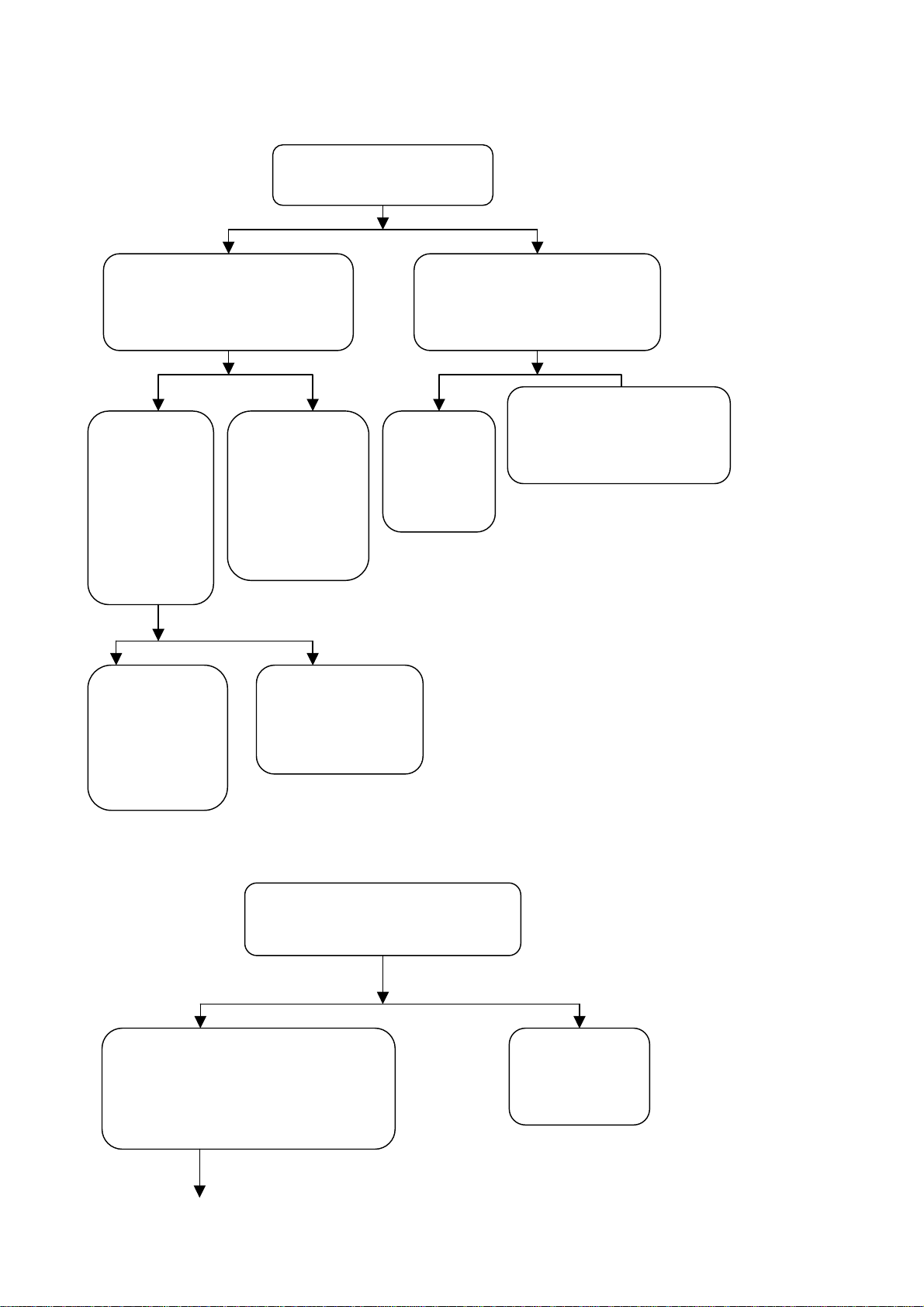
1. Process of diagnosing happening troubles
no
Yes, switch it on
no
yes
Main power switched on
Indication lamp red?
Indication lamp Yellow?
Is back lamp lit?
Check if power supply, infrared board, CPU
and peripherals (flash) and power line are in
trouble
Check if the 88th pin of CPU is square wave.
Check CPU peripherals, FLASH/SRAM
peripherals
Check if back light plate, 32th pin of CPU,
no
back light control has any problem
yes
no
Video signals of various
channels are normal
Audio signals of various
channels are normal.
no
Check if the input signal of this channel to
IC pin is normal. Or consider if IC and its
peripherals and LVDS output are normal
Check if the channel input signal to IC pin is
normal. Or consider if
IC(MPS7720/MSP3410) and its peripherals
are normal
19
Page 22

2.Tr ouble of 3-no’s (no r ast er, no picture and no sound)
r
y
b
h
b
l
m
i
d
h
N
q
N
t
p
N
If power indication lamp is lit
yes no
no yes
normal abnormal
abnormal normal
yes no
no yes
CPU(N501),FLASH(
N502),GAL(N553),re
set the power supply
of IC(N552)
Check the pin
voltage of
N902,D903
Check if 88th pin of N501 is
Check crystal oscillation of
501 and N501
Is indicato
Check
uare wave.
s
ellow?
eck if I2C bus
ine of the syste
s short circuite
Check if the 50thpin
of CPU is of hig
3-no’s
Disconnect data processing
oard with infrared board
X793,and then see whic
board is out of order.
Check N552 and
501
Check if 8th pin of N553 is
of high electric level
Check Standby5V
Disconnect power supply
board with data processor
and measure Standby5V
Powers supply
oard in trouble
Yes no
Check peripherals of
501,N502 and N503
Take out R509,check the relevan
ins of N501and N553. Low electric
level shows the chip is in trouble
Note:When the electric level of the 50th pin of N501is measured low, take R554 out.
Then check if the relevant pins of N501 and N552 are of high electric level. Low electric
level shows that the chip is in trouble. During the check of the peripherals of N501,N502
and N503,oscilloscope can be used to detect the pins of the resistor array connected
20
Page 23

between N501,N502 and N503, in addition to inspect the welding condition of relevant
p
p
f
d
put
p
t
parts and fittings. If the waveform detected is of regular square wave or no signal, it
shows that N501 or N502 or N503 is abnormal so that the address link and data link
between them become out of order. Now most probably N502 has error.
3.With sound but without picture
yes No
yes no
N101 and
eripheral
Try other channels see if all
without
ictures.
Sound yes but picture no
Is back lamp lit?
Transferred to(4) inspection
Check back lamp board i
back light control by 32
n
Note: The no picture phenomena in channel discussed here refers to that detected
TV,AV and terminal S are detected to be with sound but without picture. As to inspection
details of other channels, please refer to inspection program(4).
4.With picture but without sound
no yes
Check if the 7th pin of power
yes no
lifier has outpu
am
Check the peripheral
circuit of the poststepof
power amplifier
Picture yes but sound no
Check if sound process board
X211has out
Loudspeaker in trouble
Check R255,R256 and see if there is
power amplification for signal input
21
Page 24

f
N
r
g
d
f
N
No yes
Check if 1st and 2ndpin
of N203 has signal input
Check on peripheral circuit of power
amplifier and power supply
Yes no
yes no
Check peripheral circuit o
supply
Check N203
peripheral circuit of
power amplifier and
power supply
201,crystal oscillation and powe
Check if
relevant channel
of N201 has
signals input
Check all levels of circuit following the
channel of audio signal input
Note:It is after the changeover by external audio switch that the audio signal of high
definition, DVI and VG A channels enters MSP3410 through. Therefore if the a udio si g nal o f
the channels above is in trouble, it is necessary to check the peripheral circuit of N704 on
the data processing board as well as the power supply.
5.A certain channel works abnormally
a). No picture in AV
yes no
yes no
Check if line/field syn. signal an
clock signal output from N101 are
Check peripheral
circuit of N601,
power supply
Check if C193 has
nal input
si
There is trouble in the
channel form AV socket to
Check peripheral circuit o
101, crystal oscillation,
power supply
22
Page 25

b). No picture for S terminal
d
f
N
g
t
d
N
g
t
f
y
yes no
Check if line/field syn. signal an
clock signal output from N101 are
normal.
yes no
Check peripheral
circuit of N601
and power supply
c). No picture in TV channel
First use the double picture function to judge whether the problem lies in the main screen or
sub-screen.
Check if C140 and C144
have si
Check peripheral circuit o
power supply
nal inpu
Problem in the channel form S
terminal socket to N101
101, crystal oscillation,
No picture in the main screen:
yes no
Check if line/field syn. signal an
clock signal output from N101 are
normal.
yes no yes no
Check
peripheral
circuit of N601
and power
supply
Check if C143 has
nal inpu
si
Check
peripheral
circuit of
101, crystal
oscillation,
power
supply
Check if 12thpin of
TUNER201 on TV has
signal output
Check circuit
betweenTUNE
R201 and N101
Check peripheral circuit o
TUNER201, power suppl
and bus line
23
Page 26
No picture in sub-screen:
m
N
g
t
m
N
f
y
N
w
yes no
Check if line/field syn. signal
and clock signal output fro
401are normal
Yes no Yes No
Check if
line/field syn.
signal and
clock signal
output from
N101 are
normal
yes no
Check
peripheral
circuit of
N601, power
supply N601
Check if 73rd pin of N401
nal inpu
has si
Check
peripheral
circuit of N401,
crystal
oscillation,
power supply
Check peripheral
circuit of N101,
crystal oscillation
Check if 12thpin of TUNER202
on TV board has signal output
Check peripheral circuit o
Check the
circuit fro
TUNER202
401
TUNER20 , power suppl
and bus line.
d). No picture in SCART1 channel
yes no
Check if the 46th pin of N501 is of lo
electric level when SCART1 has RGB
input and if it is of high level when the
latter is video input
Check if 4th,5th, 6th and 74thof
401has signal input
Trouble in
channel from
SCART1 socket
to N401
24
Page 27

N
d
k
m
N
d
d
p
y
f
N
d
f
N
f
N
d
l
yes no
yes no
yes no
e). No picture in SCART2 channel
Check if line/fiel
syn. signal an
clock signal output
from N101 are
normal
Check periph- eral
circuit of N601
ower suppl
and
supply
yes no
yes no
Check if line/field syn.
signal and clock signa
output from N101 are
no
normal
Check if line/field syn.
signal and clock signal
output from N101 are
normal
Check if line/fiel
syn. signal and cloc
signal output fro
401 are normal
Check peripheral
circuit of N401,
crystal oscillation
and power supply
Check peripheral circuit o
101, crystaloscillationan
power supply
Check if 71th and 72th pins o
401 have signal input.
Check peripheral circuit o
401, crystal oscillation an
Check the channel from
501 and N501 to
SCART1 socket
There is problem with the
channel from SCART2
socket to N401
25
Page 28
f
N
f
N
m
N
d
k
m
N
p
d
p
f
N
N
yes no
Checkperipheral
circuit of N601
and power supply
Check peripheral circuit o
101 crystal oscillation,
power supply
f).No picture in YPbPr/YcbCr channel
Check if 43rd ,48th ,49th and 54thpins o
201have signal input
yes no
Check if line/field syn. signal
and clock signal output fro
201 are normal
Check if 4th ,7th ,9
ins of N703 have
signal input
yes no no yes
yes no
Check if line/fiel
sync. signal and cloc
signal output fro
101 are normal
Check peripheral
circuit of N201,
ower supply an
bus line
Check if 3rd,
th
, 10thpins o
6
703 have
signal input
yes no
Check peripheral
circuit of N601
and power supply
Check peripheral
circuit of N101,
crystal oscillation
and power supply
Check peripheral
circuit of
N703and power
supply supply
There is problem
with the channel
from YpbPr
socket to N703
th
Check the
channel
from N703
output to
201 input
26
Page 29

g). No picture in D_Sub channel
r
n
program
(f)
l
f
N
d
p
p
A
h
p
t
r
m
yes no
Check if 30th and 31
ins of N201have syn.
signal input
yes no
There is problem with
the channel from VG
socket to N703
yes no
Check peripheral circui
of N701and powe
supply
h).No picture in DVI channel
yes no
yes no
Check peripheral
circuit, power
supply of N601
Check if line/field syn.
signal and clock signa
output from N101 are
normal
If the display of YpbP
input signal is normal
st
Check if 1st and 5t
ins of N701 have
synchr. Signal input
Trouble in channel fro
VGA socket to N701
Check if line/field syn.
signal and clock signal
output from N761 are
normal
Check peripheral circuit,
ower supply of N761and if
the connection with DVI
socket is good.
Check peripheral circuit o
101, crystal oscillation an
power supply
Check as per inspectio
27
Page 30

Note: To enable DVI picture to be displayed normally, especially to be connectable with the computer
display card, the top priority is to ensure that N762(DDC chip of DVI port) are well flash written. When
picture signal is with HDCP,it is also necessary to ensure that the KEY in HDCP of N760 are well flash
written.
7. Abnormal picture on screen
1). A certain LVDS differential line of X601 LVDS is abnormal
against(RX0+/-,RX1+/-,RX2+/-,RX3+/-), which may result in under coloring or color
speckle;
2). R602~R607 resistor array in trouble,wh ich may result in the loss of corresponding
color in corresponding gray degree for the picture of all channels;
3). R205~R210 resistor array in trouble,which may result in the loss of corresponding
color in corresponding gray degree for the picture of YPbPr/VGA channel;
4). R777~R782 resistor array in trouble,which may result in the loss of corresponding
color in corresponding gray degree for the picture of DVI channel;
5). R414 and R415 resistor array in trouble,which may result in abnormality in
the picture of SCART and TV sub screen.
28
Page 31

Page 32

Page 33

Page 34

Page 35

Page 36

Page 37

Page 38

Page 39

Page 40

Page 41

Page 42
Page 43

Page 44

Page 45
 Loading...