

Page 1

LCD TELEVISION
LC-27K16
Page 2

CONTENTS
Safety instructions………………………………………………………………………..…
Adjustment instructions …………………………….…….…………………………….…
Trouble shooting ……………………………………………………….……………………
LC-27K16 working principle analysis……………………………….………….………….
LC-27K16 block diagram…………………………………..……………………….…………
IC block diagram………………………………………………………………………..……
Main assembly……………………………………………………………………………..…
Identification criteria for the bright spot and dark spot of the LCD screen………..….
Wiring diagram ……………………………………………………………..……………...
Troubleshooting charts………………………………………………………………..……
Schematic diagram …………………………………………………………………….…..
APPENDIX: Exploded view
Part list
1
3
5
7
9
10
20
21
22
23
26
Page 3

Attention: This service manual is only for service personnel to take reference with. Before
servicing please read the following points carefully.
Safety instructions
1. Instructions
Be sure to switch off the power supply before replacing or welding any components or
inserting/plugging in connection wire Anti static measures to be taken (throughout the entire
production process!):
a) Do not touch here and there by hand at will;
b) Be sure to use anti static electric iron;
c) It’s a must for the welder to wear anti static gloves.
Please refer to the detailed list before replacing components that have special safety requirements.
Do not change the specs and type at will.
2. Points for attention in servicing of LCD
2.1 Screens are different from one model to another and therefore not interchangeable. Be sure to
use the screen of the original model for replacement.
2.2 The operation voltage of LCD screen is 700-825V. Be sure to take proper measures in
protecting yourself and the machine when testing the system in the course of normal operation or
right after the power is switched off. Please do not touch the circuit or the metal part of the module
that is in operation mode. Relevant operation is possible only one minute after the power is
switched off.
2.3 Do not use any adapter that is not identical with the TV set. Otherwise it will cause fire or
damage to the set.
2.4 Never operate the set or do any installation work in bad environment such as wet bathroom,
laundry, kitchen, or nearby fire source, heating equipment and devices or exposure to sunlight etc.
Otherwise bad effect will result.
2.5 If any foreign substance such as water, liquid, metal slices or other matters happens to fall into
the module, be sure to cut the power off immediately and do not move anything on the module lest it
should cause fire or electric shock due to contact with the high voltage or short circuit.
2.6 Should there be smoke, abnormal smell or sound from the module, please shut the power off at
once. Likewise, if the screen is not working after the power is on or in the course of operation, the
power must be cut off immediately and no more operation is allowed under the same condition.
2.7 Do not pull out or plug in the connection wire when the module is in operation or just after the
power is off because in this case relatively high voltage still remains in the capacitor of the driving
circuit. Please wait at least one minute before the pulling out or plugging in the connection wire.
2.8 When operating or installing LCD please don’t subject the LCD components to bending, twisting
or extrusion, collision lest mishap should result.
2.9 As most of the circuitry in LCD TV set is composed of CMOS integrated circuits, it’s necessary
to pay attention to anti statics. Before servicing LCD TV make sure to take anti static measure and
ensure full grounding for all the parts that have to be grounded.
2.10 There are lots of connection wires between parts behind the LCD screen. When servicing or
moving the set please take care not to touch or scratch them. Once they are damaged the screen
1
Page 4

would be unable to work and no way to get it repaired.
2.11 Special care must be taken in transporting or handling it. Exquisite shock vibration may lead to
breakage of screen glass or damage to driving circuit. Therefore it must be packed in a strong case
before the transportation or handling.
2.12 For the storage make sure to put it in a place where the environment can be controlled so as to
prevent the temperature and humidity from exceeding the limits as specified in the manual. For
prolonged storage, it is necessary to house it in an anti-moisture bag and put them altogether in one
place. The ambient conditions are tabulated as follows:
Temperature Scope for operation 0 ~ +50 oC
Scope for storage -20 ~ +60 oC
Humidity Scope for operation 20% ~ 85%
Scope for storage 10% ~ 90%
2.13 Display of a fixed picture for a long time may result in appearance of picture residue on the
screen, as commonly called “ghost shadow”. The extent of the residual picture varies with the
maker of LCD screen. This phenomenon doesn’t represent failure. This “ghost shadow” may remain
in the picture for a period of time (several minutes). But when operating it please avoid displaying
still picture in high brightness for a long time.
3. Points for attention during installation
3.1 The front panel of LCD screen is of glass. When installing it please make sure to put it in place.
3.2 For service or installation it’s necessary to use specified screw lest it should damage the screen.
3.3 Be sure to take anti dust measures. Any foreign substance that happens to fall down between
the screen and the glass will affect the receiving and viewing effect
3.4 When dismantling or mounting the protective partition plate that is used for anti vibration and
insulation please take care to keep it in intactness so as to avoid hidden trouble.
3.5 Be sure to protect the cabinet from damage or scratch during service, dismantling or mounting.
2
Page 5
Alignment instruction
1 Alignment equipment
PM5518 (video signal generator)
K-7253 (VGA signal generator)
CA210 (white balancer)
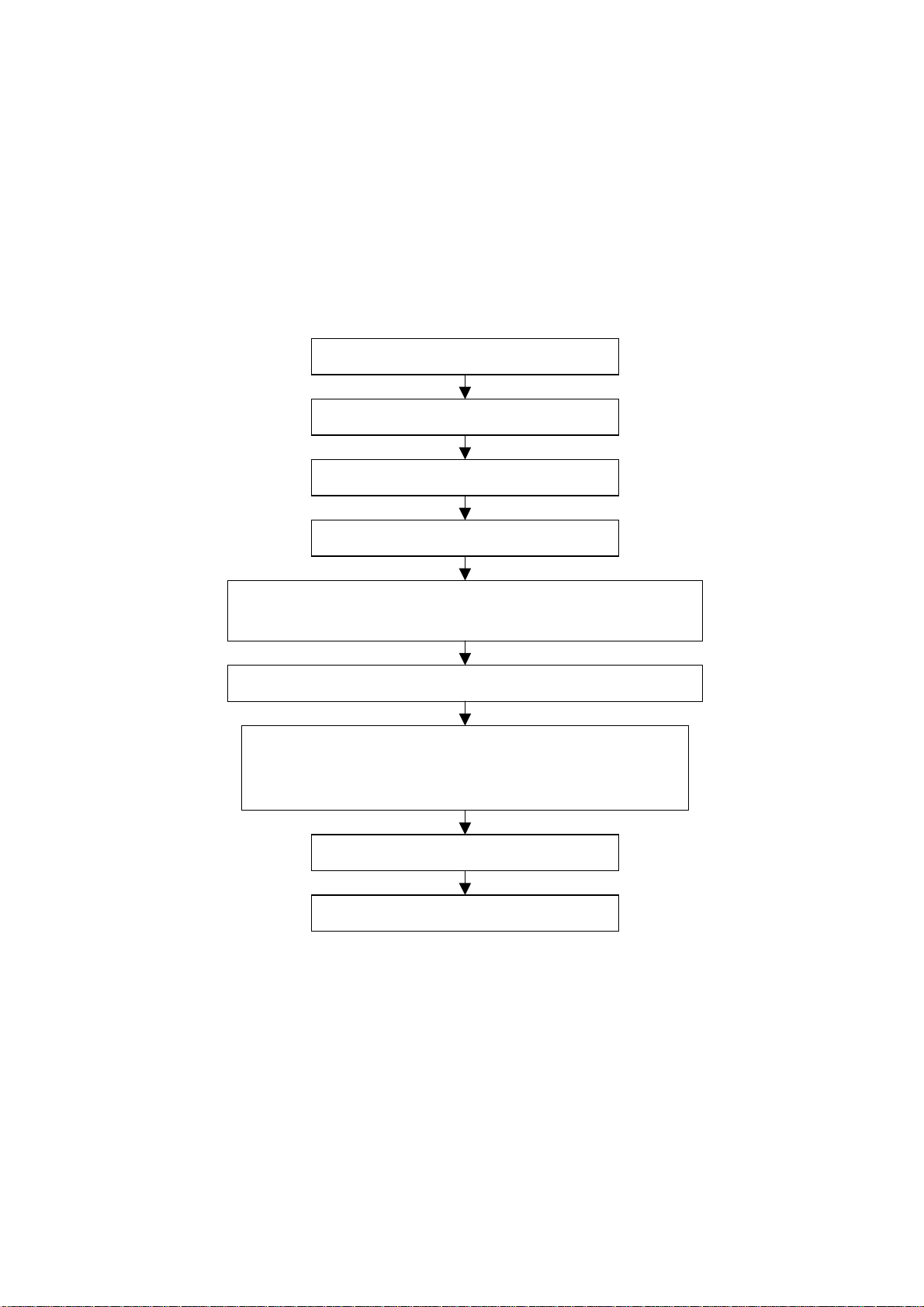
2 Alignment flow-chart
The alignment flow-chart is shown as fig-1
Check DDC, HDCP KEY and FLASH
To produce CPU board and analog board
Check the CPU board and analog board
Connect with central signal source, then check each function of TV such as
analog control etc., check the output of headphone and speaker
Input AV/S and HD signal, then check each function of all the terminals
Input VGA signal (one format), check if the displ ay is normal under PC
condition, check each function such as analog control etc., ch eck hori zont al
/vertical center etc.
Check the accessories and pack t hem in box
Fig-1 adjustment flow-chart
3 Unit adjustments
Connect CPU board and analog board according to wiring diagram, connect with power and
observe the display.
Method for entering factory menu: press “VOL+”, “MUTE” and “VIDEO” repeatedly to enter factory
menu; press “ENTER” to select different items when the first line of each adjustment item just lights
up; input VGA and DVI signal, then select the “mode” item; after that, you can press “enter” to select
three kinds of color temperature namely 6500K, 9300K and 12000K press “MENU” to exit.
Note: the white balance adjustment should be done under “nature” picture mode.
All testing
Preset ex-factory
3
Page 6

3.1 EEPROM initialization
Enter the first page of factory menu, select “clear eeprom” and then press “enter”, shut down the
unit after “ok” appears.
3.2 VGA/DVI channel adjustment
3.2.1 Preset VGA channel mode
Input VGA signal (PATTERN 5: Final Test) of K-7253, select TIME301(640*350/70Hz), press
“AUTO” to do the auto adjustment until the screen is filled with picture. Use the same method to do
auto adjustment for the following items:
TIME302 (720*400/70Hz) TIME303 (640*480/60Hz) TIME311 (800*600/60Hz)
TIME313 (1024*768/60Hz) TIME315 (640*480/75Hz) TIME316 (800*600/75Hz)
TIME317 (1024*768/75Hz) TIME319 (1280*1024/75Hz) TIME339 (1280*1024/60Hz)
3.2.2 ADC adjustment of VGA channel
Input K-7253 64 level gray-scale signal of TIME311 and PATTERN474, adjust ADC-gain to its
maximal (not above 18) to let the brightest two levels can be recognized.
3.2.3 White balance adjustment VGA/DVI channel
Input K-7253 64 level gray-scale signal of TIME311 and PATTERN474, enter white balance
adjustment menu; adjust the third and seventh levels using white balance.
Select 6500k of “mode”, adjustment offset_R, offset_G and offset_B, let the color coordinate of the
third level be 308 and 316 and its brightness be 12.5nit more or less. Adjust gain_R, gain_G and
gain_B, let the color coordinate of seventh level be 308 and 316.Adjustment offset_R, offset_G,
offset_B, gain_R, gain_G and gain_B repeatedly until the value of the two levels gray-scale be 308
and 316.
Select 9300k of “mode”, adjustment offset_R,offset_G and offset_B,let the color coordinate of the
third level be 285 and 290 and its brightness be 12.5nit more or less. Adjust gain_R,gain_G and
gain_B, let the color coordinate of seventh level be 285 and 295.
Select 12000k of “mode”, adjustment offset_R, offset_G and offset_B, let the color coordinate of the
third level be 270 and 283 and its brightness be 12.5nit more or less. Adjustment offset_R, offset_G,
offset_B, gain_R, gain_G and gain_B repeatedly until the value of the two levels gray-scale be 270
and 283.
Note: gain_R, gain_G, gain_B is value not above 128 and let its value 128 at least.
3.3 Adjustment TV channel
3.3.1 Adjustment VCO, OPTION, sub-brightness and sub-contrast
input AV color bar signal(PM5518 COLOR BAR 100%) to VIDEO 1 terminal,enter the first page of
factory menu, press “enter” selecting “auto color” display “OK” after 2 seconds, then you can finish
the VCO adjustment; set the value of “option” to 9 and s-bright to 150 as well as S-contrast to 140.
set the MaxVolume according to its product standard. Set value of page VPC3230 to 0,0,3,3,3,3,0.
3.3.2 white balance adjustment of TV channel
Input AV signal (PM5518, NTSC system, 8 level gray-scale signal), enter adjustment menu of white
balance, adjust the third level and seventh level using white balance. Adjust offset_R, offset_G and
offset_B to let color coordinate of the third level be 285 and 290 and its brightness be about 12.5nit.
fixate gain_B, adjust gain_R, gain_G to color coordinate of the seventh level be 285 and 290. adjust
4
Page 7
offset_R, offset_G,offset_B, gain_R and gain_G, repeatedly using the same method until the value
of the two levels gray-scale be the specified value.
3.4 white balance adjustment YPbPr channel
input YpbPr signal of K-7253 to YPbPr-1 terminal, input TIME380(480i) PATTERN471 8 level
gray-scale signal, set the value of S-bright to 120 and S-contrast to 140.Enter adjustment menu of
white balance, adjust the third level using white balancer. Adjust offset_R, offset_G and offset_B, to
let color coordinate of the third level be 285 and 290 and its brightness be about 12.5nit.
Input 8 level gray-scale signal of TIME392(480p), TIME394(720p) and TIME396(1080i) separately,
repeat the above operations to let color coordinate of the third level be 285 and 290 and its
brightness be about 12.5nit.
4 Performance check
4.1 TV function
Enter searching menu → auto search, connect RF-TV terminal with central signal source and check
if there are channels be skipped
4.2 AV/S, YpbPr terminals
Input AV/S, HD signal, check if it is normal.
4.3 VGA terminal
Insert VGA terminal, input VGA format signal of 640 X 480@60 Hz, check if the display is normal. If
interference exists, press the auto adjust button on remote control again and check if it is normal.
4.4 DVI terminal
Insert DVI terminal, input signal of 640 X 480@60 Hz signal and check if the display is normal.
4.5 check sound channel
Check the speaker and headphone of each channel.
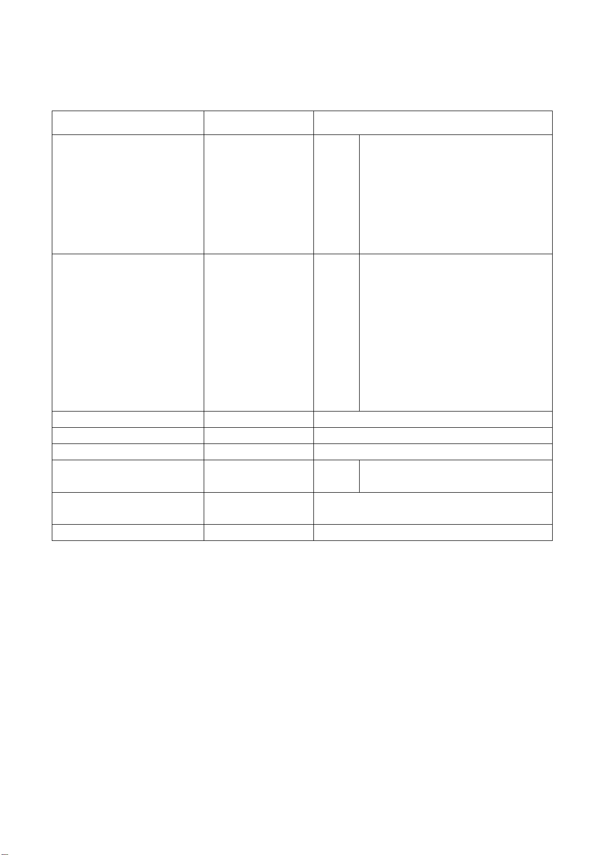
4.6 presetting before ex-factory
item setting item setting item setting
Picture mode NATURE OSD language English BALANCE 50
Sound mode NEWS VGA color
N/R WEAK SPEAKER ON CCD OFF
SCREEN 16:9 HEAD PHONE ON Turn off TV
12000 SRS OFF
temperature
Trouble shooting
Before servicing please check to find the possible causes of the troubles according to the table
below.
1.Antenna(signal):
Picture is out of focus or jumping Bad status in signal receiving
Poor signal
Check if there are failures with the electrical connector or
the antenna.
Check if the antenna is properly connected.
5
Page 8
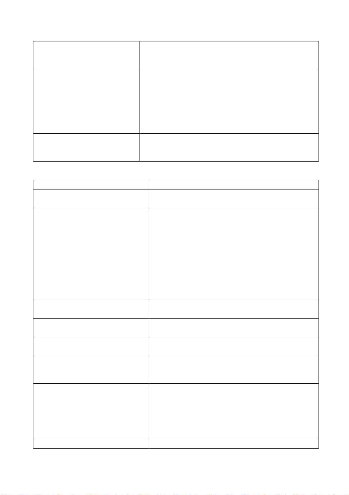
Fringe in picture Check if the antenna is correctly oriented.
Maybe there is electric wave reflected from hilltop or
building.
Picture is interfered by stripe
shaped bright spots
There appear streaks or light color
on the screen
Possibly due to interference from automobile, train, high
voltage transmission line, neon lamp etc.
Maybe there is interference between antenna and power
supply line. Please try to separate them in a longer
distance.
Maybe the shielded-layer of signal wire is not connected
properly to the connector.
Check if interfered by other equipment and if interfered
possibly by the equipment like transmitting antenna,
non-professional radio station and cellular phone.
2.TV set:
Symptoms Possible cause
Unable to switch the power on Check to see if the power plug has been inserted
properly into the socket.
No picture and sound Check to see if the power supply of liquid crystal TV
has been switched on. (As can be indicated by the
red LED at the front of the TV set)
See if it’s receiving the signal that is transmitted from
other source than the station
Check if it’s connected to the wrong terminal or if the
input mode is correct.
Check if the signal cable connection between video
frequency source and the liquid crystal TV set is
correct.
Deterioration of color phase or color
tone
Screen position or size is not proper Check is the screen position and size is correctly set
Picture is twisted and deformed Check to see if the picture-frame ratio is properly set
Picture color changed or colorless Check the “Component” or “RGB” settings of the
Picture too bright and there is
distortion in the brightest area
Picture is whitish or too bright in the Check if the setting for the brightness is too high
Check if all the picture setups have been corrected.
up.
up.
liquid crystal TV set and make proper adjustment
according to the signal types.
Check if the contrast setting is too high.
Possibly the output quality of DVD broadcaster is set
too high.
It maybe also due to improper terminal connection of
the video frequency signal in a certain position of the
system.
6
Page 9

darkest area of the picture Possibly the brightness grade of DVD player
(broadcaster) is set too high.
No picture or signal produced from the
displayer if “XXX in search” appears.
There appears an indication - “outside
the receivable scope)
Remote control cannot work properly Check if the batteries are installed in the reverse
No picture and sound, but only hash. Check if the antenna cable is correctly connected, or
Blur picture Check if the antenna cable is correctly connected.
No sound Check if the “mute” audio frequency setting is
When playing VHS picture search
tape, there are lines at the top or
bottom of the picture.
Check if the cable is disconnected.
Check if it’s connected to the proper terminal or if the
input mode is correct.
Check if the TV set can receive input signal. The
signal is not correctly identified and VGA format is
beyond the specified scope.
order.
Check if the battery is effective.
Check the distance or angle from the monitor.
Check if there is any obstruct between the remote
control and the TV set.
Check if the remote control signal- receiving window
is exposed to strong fluorescence.
if it has received the video signal correctly.
Of if it has received the right video signal.
selected.
Check if the sound volume is set to minimum.
Make sure the earphone is not connected.
Check if the cable connection is loose.
When being played or in pause VHS picture search
tape sometimes can’t provide stable picture, which
may lead to incorrect display of the liquid crystal TV,
In this case please press “auto” key on the remote
control so as to enable the liquid crystal TV set to
recheck the signal and then to display correct picture
signal
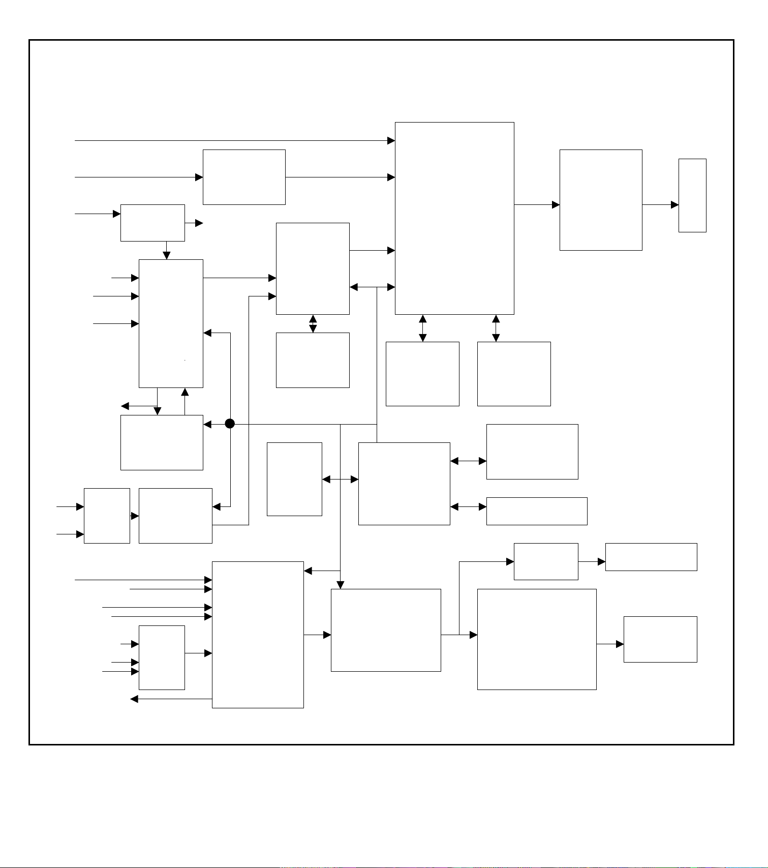
LC-27K16 working pr inciple analysis
Please refer to LC-27K16 BLOCK DIAGRAM in order to know the working principle of LC-27K16
brief introduction to its signal flow is shown as follows:
RF signal produces composite color television signal through TUNER201, the signal together with
AV1/SVHS (SVHS priority), AV2 etc. are sent to U29 VPC3230D to decode and do switching
selection. In addition to decode the selected video signal, part of the selected video signal is also
sent to AV terminal and 21 line decoder U32 Z86229 which is exclusive to decode CCD/V-CHIP to
7
Page 10

decode. After decoded by U32, the signal will be sent back to U29 in the form of R G B and FB, then
it will be added to the decoded picture and then it will be sent to U13 FL12310 in the form of
ITU-R656 signal format of 8BIT to do line-by-line process.
Send two ways YPRPB signal to U30 MST9883 through selection by N2 PI5V330 in order to do the
A/D conversion. After this, the signal will be converted into YUV signal of 24BIT, send it to FLI2310
also.
After a series of procedure such as matrix, chroma and tint etc. by FL12310, the two ways signal will
be converted into RGB of 24bit, then send it to the main processing chip U12 JAG-ASM. Send RGB
signal it to the main processing chip U12 at the same time. There has another signal, which should
be sent to U12 together with he above two kinds of signal that is: RGB signal of 24BIT produced by
DV1 through U15 TFP403/501. Do the picture format processing for the three kinds of signal in U12.
Firstly do the A/D conversion for RGB signal of VGA, and then do the switching selection together
with the other two kinds of signal. And then they will be converted into 1024*768 format through
digital display processing such as OSD and GAMMA correction etc. output it in the form of 24BIT
RGB signal. Send it to LVDS convertor U31 DS90C383A, then it will be converted into signal format
which can be accepted by LCD screen namely 3 low-voltage differential signal and 1 clock signal,
finally send it to LCD screen to do the picture display PWM of U12 can also be used to control the
brightness of back light-source.
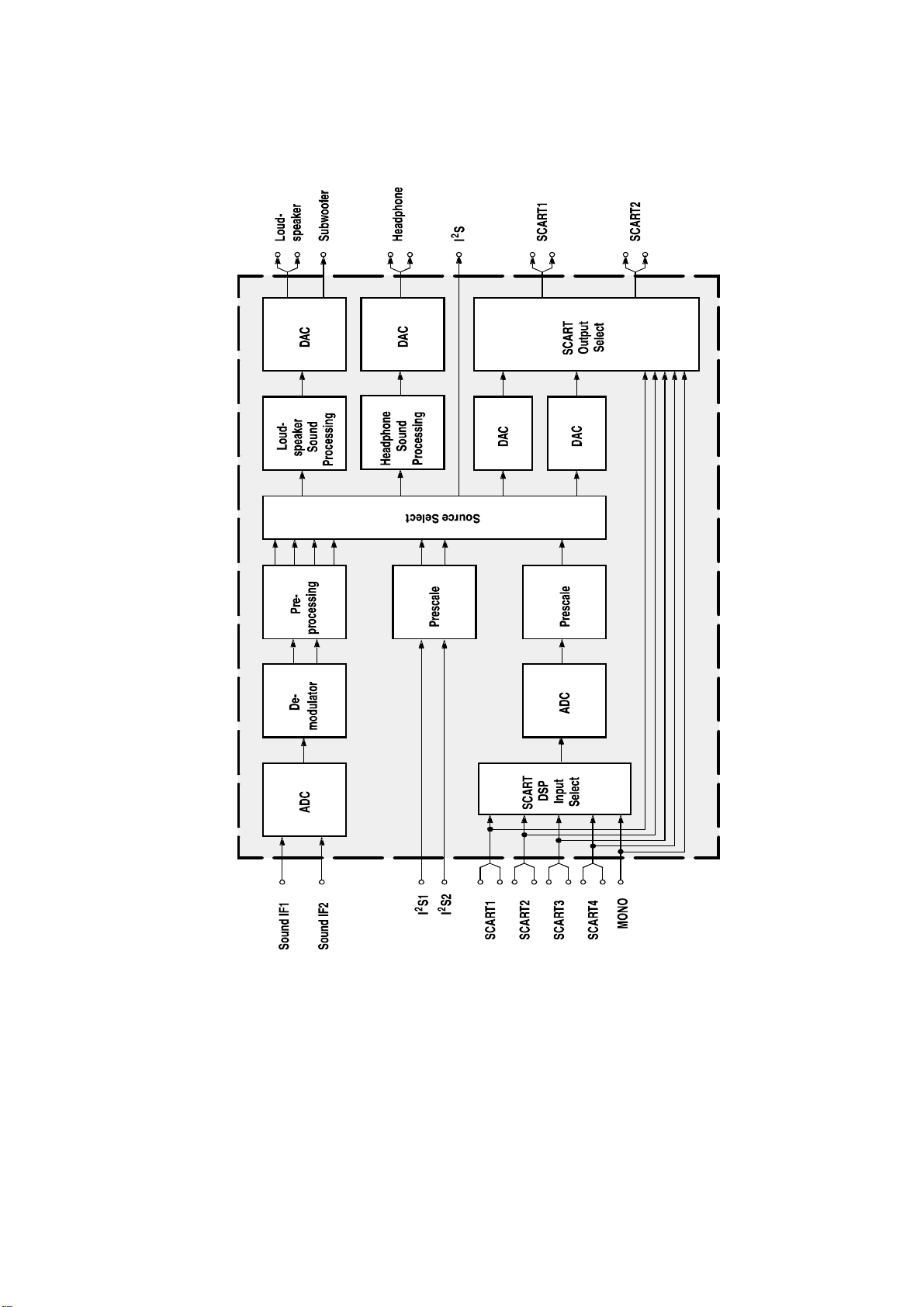
Send SIF (the second IF) outputted by tuner to audio processor N201 MSP3420; send YPRPB and
audio signal of DVI to N201 through switching selection by U34 HEF4052; Send AV1/SVHS, AV2
and audio signal of VGA to N201 also. Firstly SIF will be done the switching selection together with
another four ways of audio signal; finally volume control and sound effect processing will be done.
Output left-right sound channel signal R/L. one will be sent to SRS sound field processor N203
M62494 to do SRS processing and finally amplified by N213 and N214 MP7720 to drive the speaker,
one will be used to drive the headphone through N212 TLE2142 and the last part will be outputted
as R/L of AV OUT.
8
Page 11
N
N
N
N
LC-27K16 BLOCK DIAGRAM
RGB
RGB
24bit
U15 DVI
DRIVER
TFP501
RGB
RF 24bit
SIF
RGB
V 24bit
ITU-R656
AV1-V/S-Y 8bit
SVHS-C
TUNER
201
VPC3230
VIDEO DECODER
U29
U13
DEINTER
LACER
FLI2310
AV2 -V
U14
SDRAM
V RGB
AV-V OUT FB I IC BUS
YprPb1
PI5V330
YprPb2 YUV
24bit
U32 CCD
Z86229
2
V-CHIP
U30
ADC
MST9883
U3
EEPROM
U2
MICROCONTROLER
TSC80251G2D
R/L
SIF
AV1/SVHS-R/L
AV2-R/L
VGA-R/L R/LR/L
U34
HEF4052
R/L R/L
YprPb1-R/L R/L R/L
YprPb2-R/L
201
AUDIO
PROCESSOR
MSP3420
203
SRS 3D STEREO
CONTROLLER
M62494
DVI-R/L
AV-R/L OUT
SCALER
JAG-ASM
U19
SDRAM
U12
U31
DS90C385A
U20
SDRAM
U4
FLASH
MEMORY
IR / KEYBOAD
212
TLE2142
N213 N214
AUDIO
AMPLIFIER
MPS7720
PANEL
LVDS
DRIVER
HEADPHONE
SPEAKER
9
Page 12
IC block diagram
1.MSP3420
Pins description:
47: DVI/YPRPB1/YPRPB2-L input
48: DVI/YPRPB1/YPRPB2-R input
50: VGA-L input
51: VGA-R input
53: AV2-L input
54: AV2-R input
56: AV1-L input
57: AV1-R input
67: SIF input
10
Page 13
25: earphone-L input
24: earphone-R input
27: R output
28: L output
36: AV-R output
37: AV-L
2: SCL
3: SDA
11,12,13; 39; 65,66: +5V—MSP
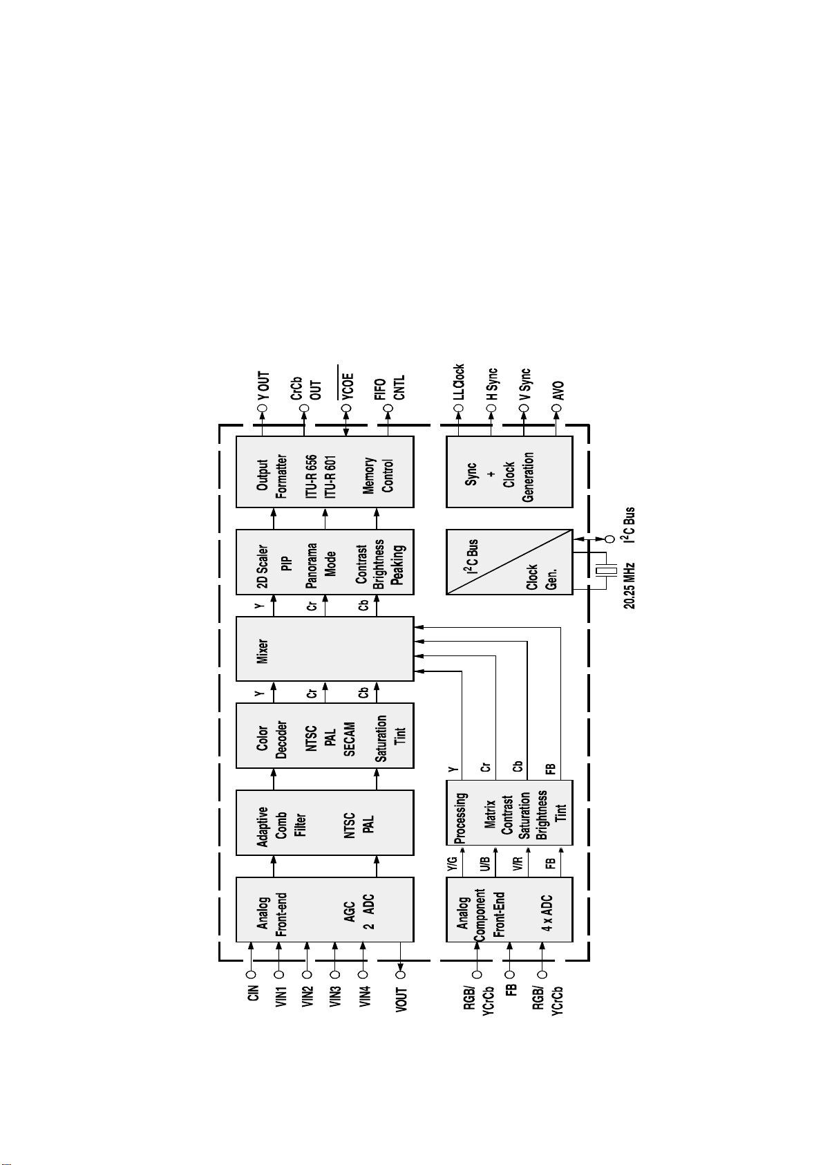
2.VPC3230
Pins description:
70: AV-V output
11
Page 14
71: C output
72: Y/AV1-V output
74: AV2-V output
75: TV-V output
31-34,37-40: ITU-R656 format signal output
27: CLK output
13: SCL
14: SDA
10,29,45; 52: 3.3V_VPC
59,69,76: 5V
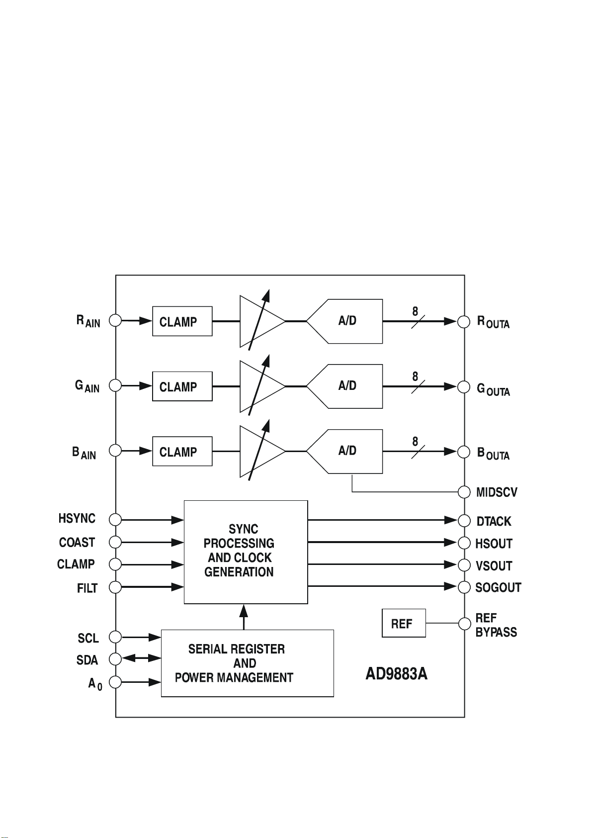
3.AD9883
Pins description:
54,48,43: YPRPB input
12
Page 15
9-2: Y output
19-12: U output
77-70: V output
56: SCL
57: SDA
66: H-SYNC output
64: V-SYNC output
65: DE output
67: CLK output
11,26,34: 3.3V
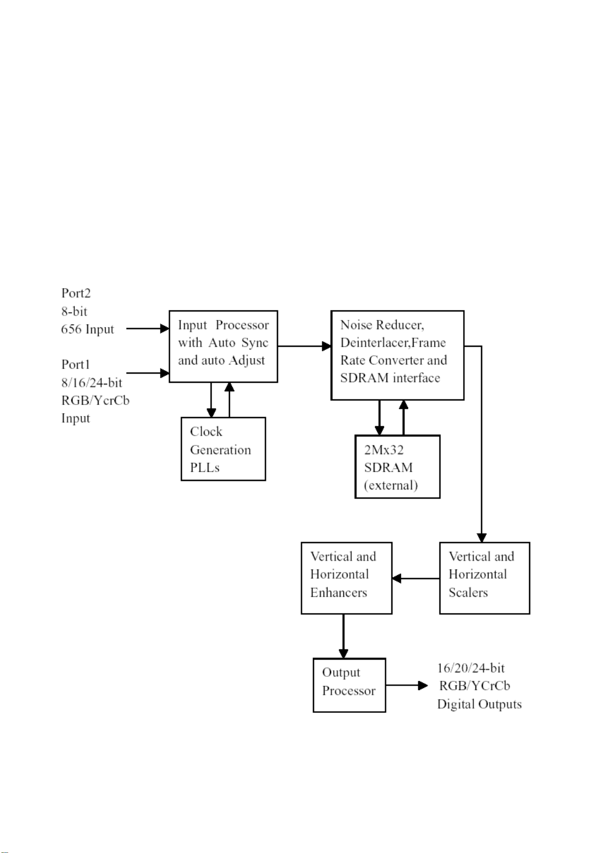
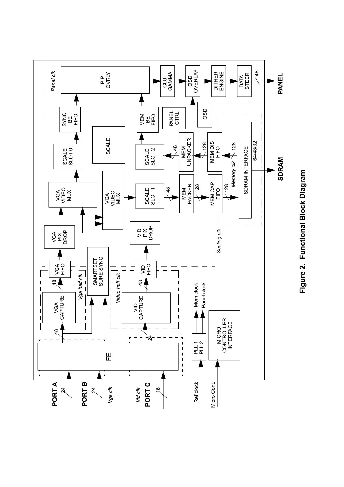
4.FLI2310-Simplified Internal Block Diagram
13
Page 16

Pins description:
196,199-205: ITU-R656 format signal input
11-15,18-20: U input
21-28: V input
29,32-35,38-40: Y input
1: YPRPB H-SYNC input
2: YPRPB V-SYNC input
4: YPRPB-CLK input
5: YPRPB-DE input
195: AV/TV-CLK input
114: SDRAM-CLK input
136,137,140-145: R output
148-155: G output
126,127,130-135: B output
125: CLK output
111: SDRAM-CLK output
118: H-SYNC output
119: V-SYNC output
120: DE output
45: SCL
46: SDA
8,62,112,193; 171,187: 3.3V
155,168; 16,68,123,197: 1.8V
14
Page 17
5.JAG-ASM
Pins description:
A12, A13: VGA-R input
A16, A17: VGA-G input
15
Page 18

A20, A21: VGA-B input
P1, P2, N2, N3, M1-M4: DVI-B input
L1-L4, K2-K4, J1: DVI-R input
J2-J4, H1-H3, G1, G2: DVI-G input
AA2, AA3, Y1-Y3, N1-N3: AV/TV/YPRPB-B input
N4, V1-V4, U1-U3: AV/TV/YPRPB-G input
U4, T1-T4, R1-R3: AV/TV/YPRPB-R input
AB3: DVI H-SYNC input
AB1: DVI V-SYNC input
G4: DVI-CLK input
F1: DVI-DE input
D6: VGA H-SYNC input
P3: VGA V-SYNC input
F2: AV/TV/YPRPB H-SYNC input
G3: AV/TV/YPRPB V-SYNC input
P4, AA4, AF12: AV/TV/YPRPB-CLK input
G6: AV/TV/YPRPB-DE input
AD13-15, AE13-15, AF14, and AC15: R output
AF15, AC16, AD16, AE16, AD17, AE17, AF17, AC18: G output
AD18, AE18, AF18, AC19, AD19, AE19, AD20, AE20: B output
AE21: H-SYNC output
AC21: V-SYNC output
AC13: CLK output
AF20: EN output
AD21: EN VDD output
AF22: EN BKL output
B1: PWW output
F3: SCL
F4: SDA
B22, C22, D20, C21; H4; D21; AC8: 2.5V
D7; A5; A26; AF10: 3.3V
C10, D10-D19: JA2.5V1
C8, D8, D9: JA2.5V2
16
Page 19
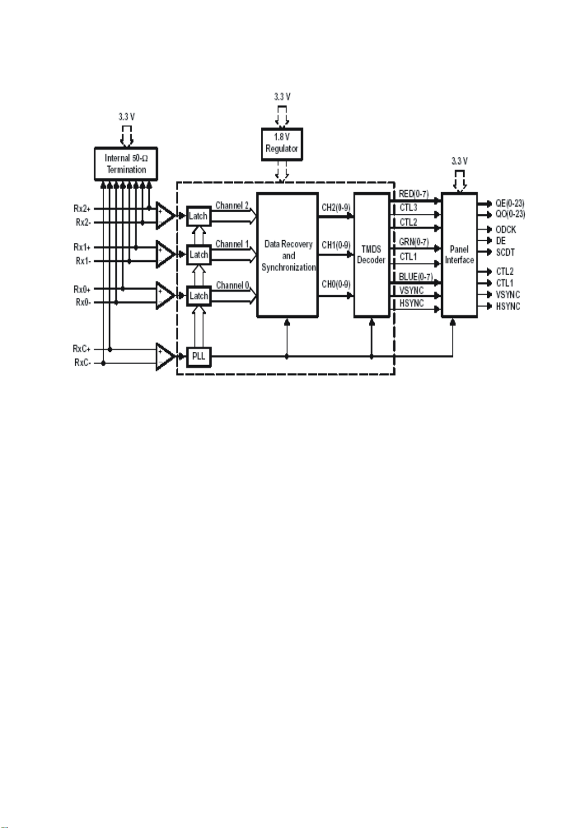
6.TFP403
Pins description:
80,8183,84,86,87,89,90: DVI input
92: DDC-SCL
93: DDC-SDA
95: PROM-SCL
96: PROM-SDA
2: POWER DOWN input
9: OUTPUT DRIVE POWER DOWN input
8: sync detection output
10-17: B output
20-27: G output
30-37: R output
44: CLK output
46: data enable output
47: H-SYNC output
48: V-SYNC output
6,38,82,91,18,29,57,78,97: 3.3V
17
Page 20
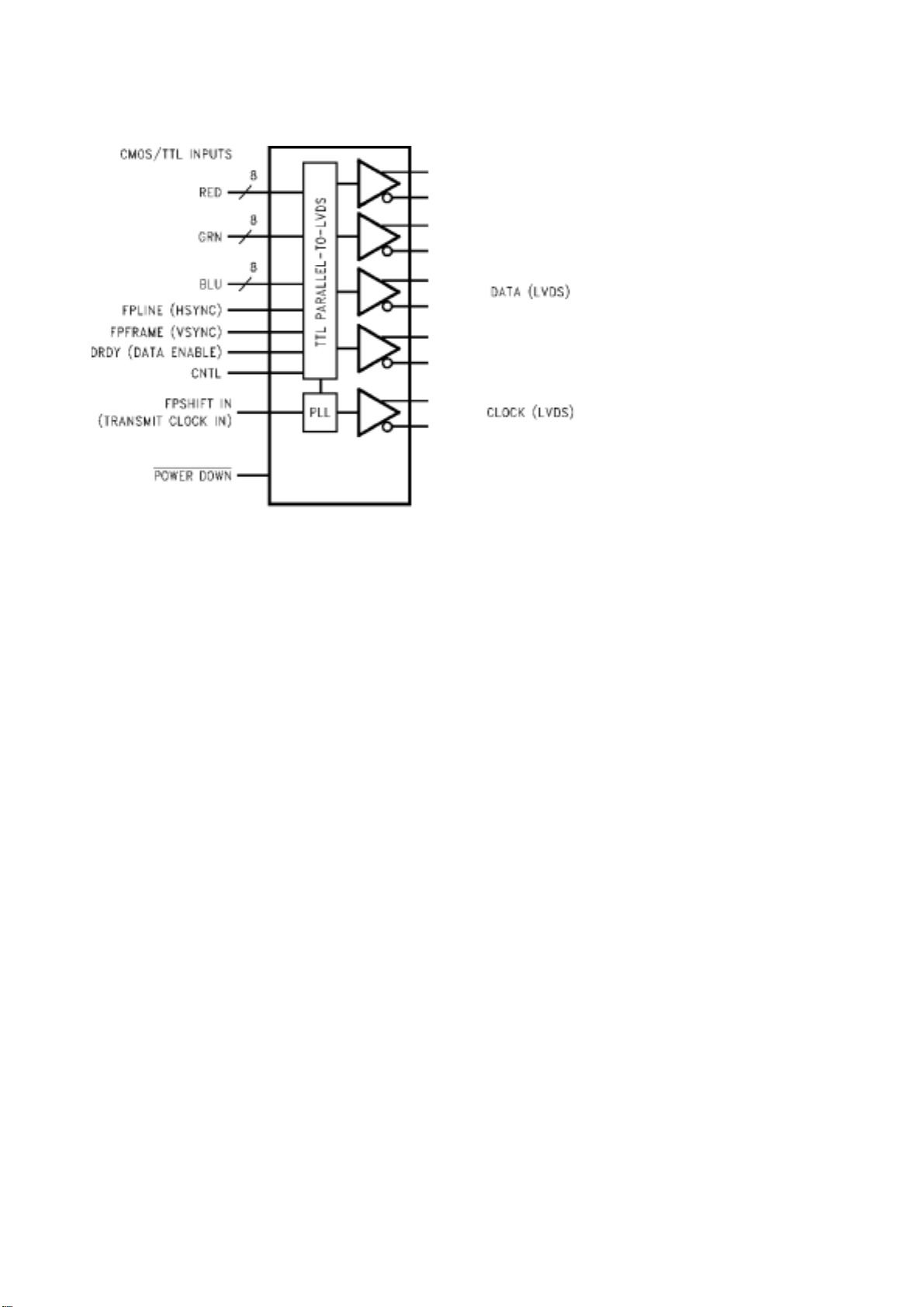
7.DS90C383
51,52,54-56,3,50,2: R input
4,6,7,11,12,14,8,10: G input
15,19,20,22-24,16,18: B input
27: H-SYNC input
28: V-SYNC input
30: data enable input
31: CLK input
32: power supply enable input
37,38,41,42,45,46,47,48: 4 pair differential signal output
39, 40: 1pair clock signal output
1, 9, 26, 34, 44: 3.3V
18
Page 21
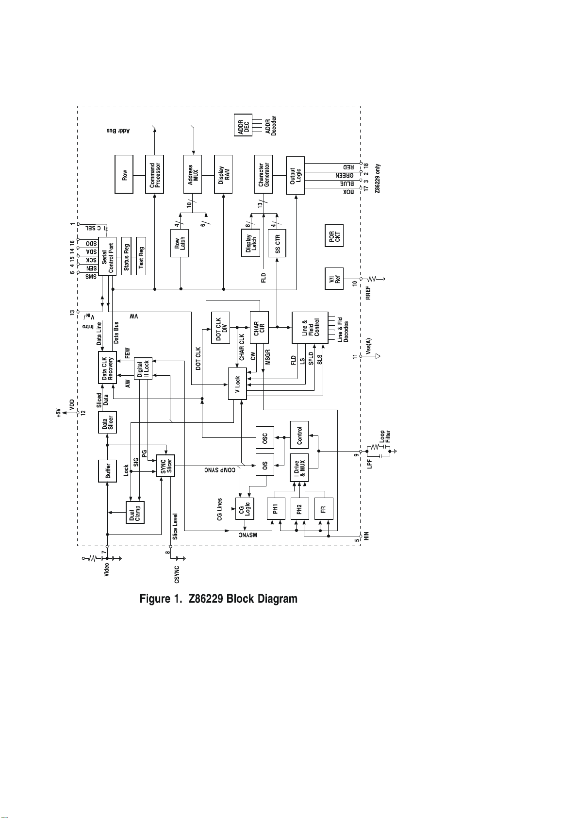
8.Z86229
Pins description:
7 PIN: VDIEO INPUT
2 PIN: G OUTPUT
3 PIN: B OUTPUT
18 PIN: R OUTPUT
17 PIN: FB OUTPUT
19
Page 22
Main assembly
NAME NO. MAIN COMPONENT AND it’S NO.
Sound conversion board
CPU board
IR board
Keypad board
Video process board
Power supply board
Remote control
(
RC-U38R-0A)
Panel
667-L27K6-15 N201
667-L23K6-56 U4
667-L27K16-09
667-L27K6-05
667-L27K6-40
667-L27M6-20
301-UL27K6-38RA
335-27001-00
N203
N213
N214
U2
U32
U31
U30
U29
U15
U13
U12
N904
V905
MSP3420G-Q (353-34200-10)
M62494FP (353-62494-20)
MPS7720 (353-77200-10)
AT49F002NT (352-49002-70)
TSC80251G2D (353-80251-10)
Z8622912SS (353-86229-10)
DS90C385 (353-03850-20)
MST9883B (353-98830-10)
VPC3230D (353-32300-80)
TFP501 (353-05010-00)
FLI2310 (353-23100-00)
JAG-ASM (353-0JAG0-00)
H11A817 (352-08170-50)
SPP11N60C3 (343-00600-60)
20
Page 23
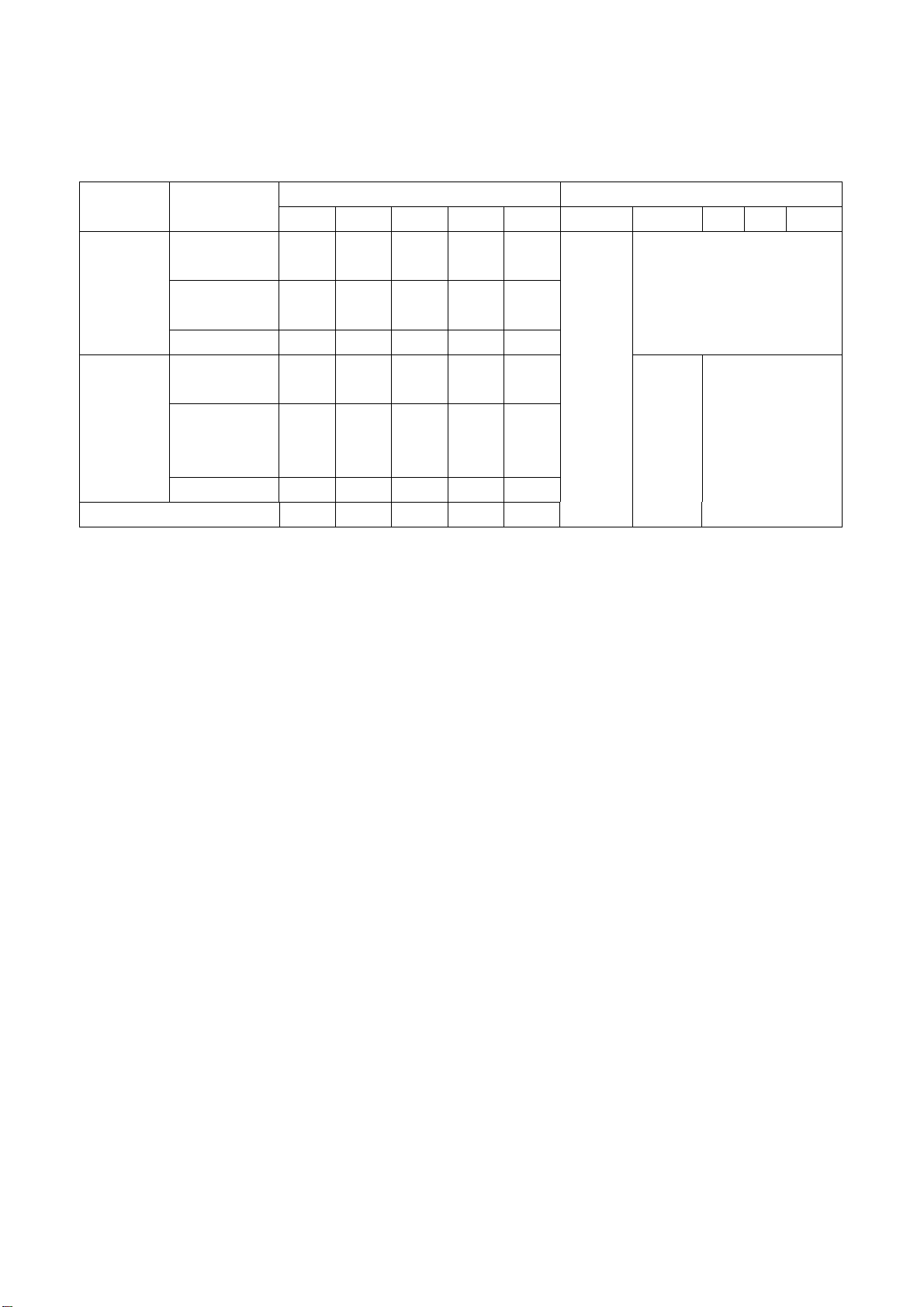
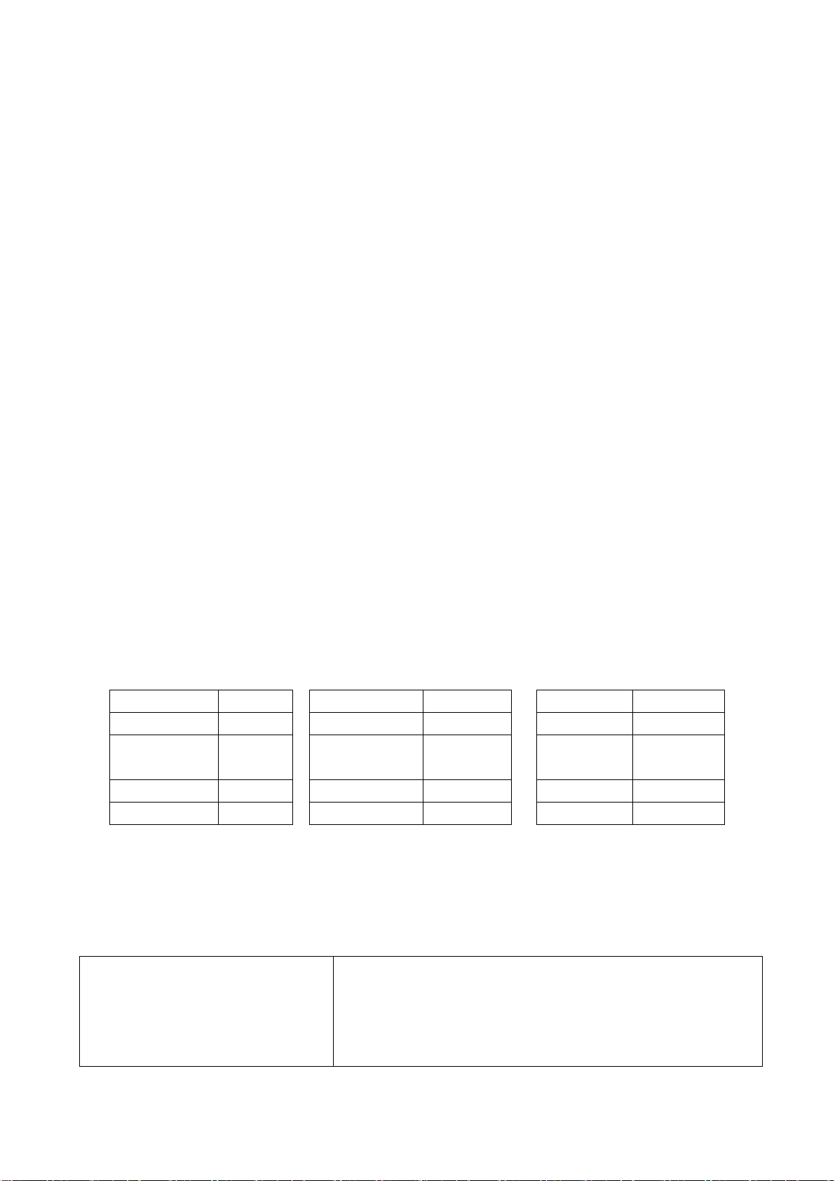
Identification criteria for the bright spot and dark spot of the LCD screen
Category criteria
One single
Bright
t
spo
Dark
spots
Total defected point ≤8 ≤7 ≤5 ≤4 /
spot
2 neighboring
spots
Total No. ≤5 ≤2 ≤5 ≤2 ≤3
One single
spot
Two
neighboring
spots
Total No. ≤6 ≤7 ≤5 ≤4 ≤10
15" 20" 22" 30" 40" 15" 20" 22" 30" 40"
≤5 ≤2 ≤5 ≤2 ≤3
≤2 ≤1 ≤2 ≤1 ≤1
≤6 ≤7 ≤5 ≤4 ≤10
≤2 ≤2 ≤2 ≤1 ≤5
Q’ty allowed Distance between two spots
≥15mm
≥15mm
≥10mm
≥5mm
Notes:
1. Definition of defected point (bright spot, dark spot): It is identified as a defected point if its area
exceeds 1/2 of a single picture element (R,G,B).
2. Definition of bright spot: It is identified as a bright spot if it is bright in the state of dark field and its
bright size remains unchanged
3. Definition of dark spot: It is identified as a dark spot if it is dark in the state of white field and its
dark size remains unchanged
4. Definition of two neighboring points: Defects of a group of picture elements(RB,RG,GB).
21
Page 24
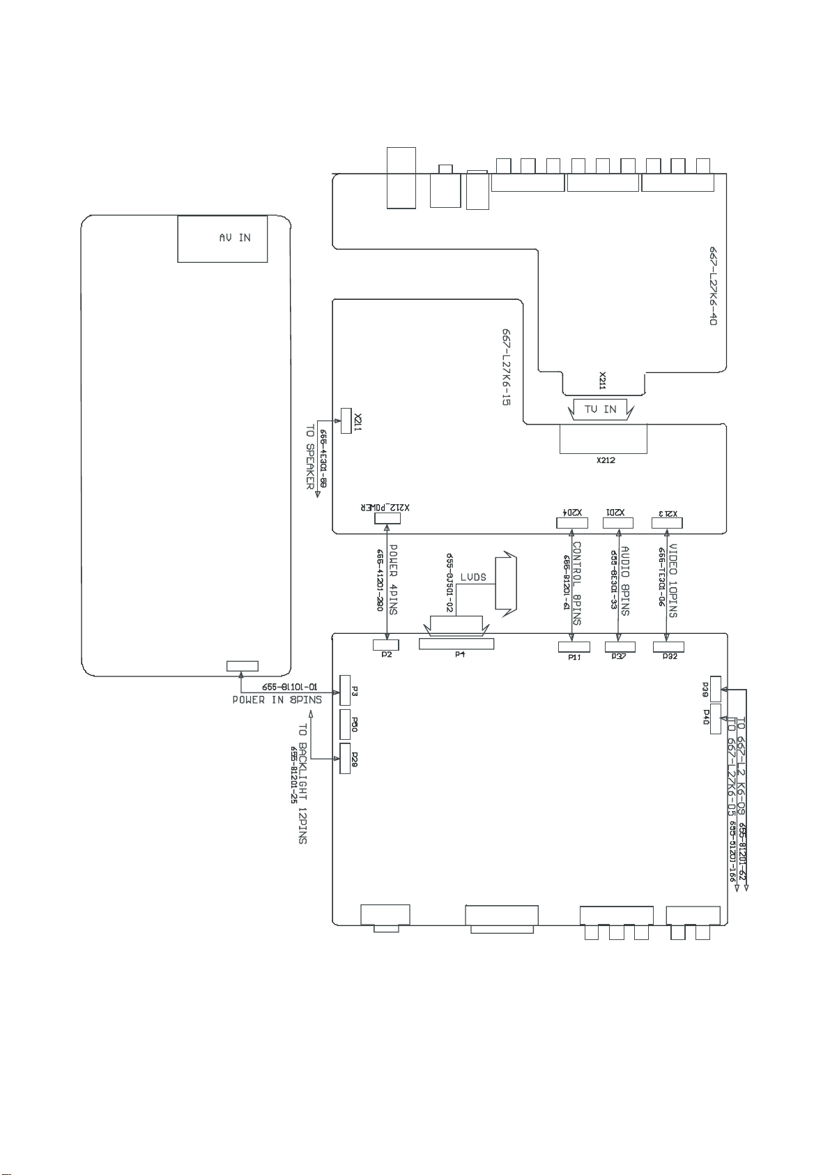
Wiring diagram
667-L27M6-20
667-L27K6-56
22
Page 25
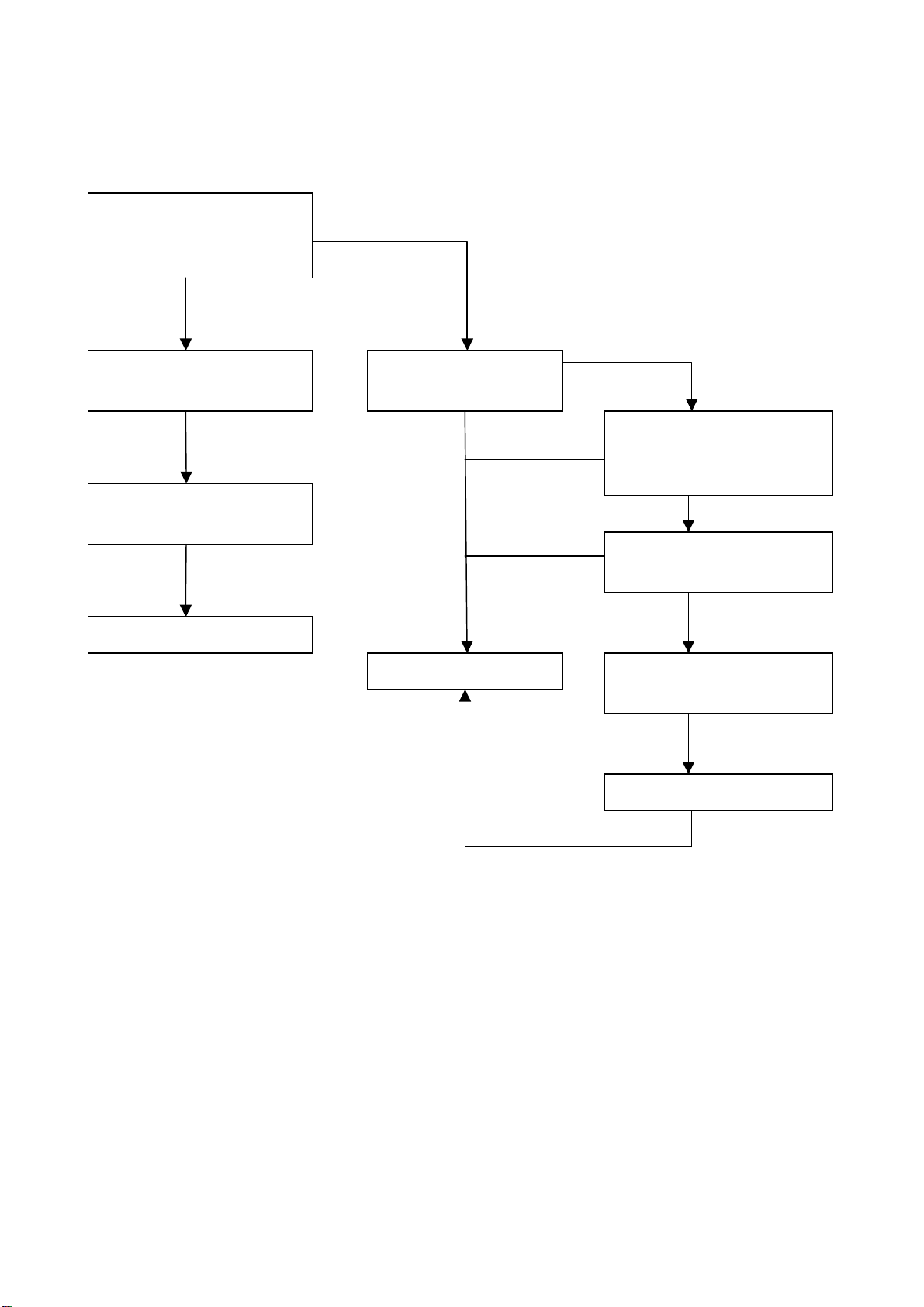
Troubleshooting guide
k
n
r
N
1. No raster
Turn-on power supply, chec
if the red indicator is light in
the STANDBY?
Check PIN6-8(24V output) of
the power supply board X903
Check if it’s melted of FUSE
in the power supply board?
Replacing power supply board
no
no
no
yes
Check the indicator i
turn-on condition
on-change color
Replacing CPU board
no
no
no
blue
Check if the indicator is flicke
in the sensor control normal
condition?
yes
Check if the PIN12 of P29 is
high-level?
yes
Check if the PIN26-30 of P4 is
high-level?
no
Check if it’s melted of F3?
23
Page 26

2. raster, but no picture
t
l
R
n
f
f
U
p
V
A
f
l
f
Check if the uni
can operation?
Replacing
CPU board
no
Enter factory-menu,
operation CLEA
no
EEPROM, then tur
off , turn on again , it i
display picture.
Adjust CPU board
Replacing
U30
no
Testing
PIN65 o
U30 SYNC
signal
Replacing U13
Check if the al
channels have signal?
yes
again
yes
Replacing CPU board
Display
“NO-SIGNAL”
Testing
no
1VPP signa
of TP1,
TP2, TP3.
YPRPB
no
yes
yes
noyes
Which is no
signal o
channels
TV
Testing power
supply (+5V-V)
of video
rocessing board
yes
Check if PIN2
1VPP signal
and noise wave
of P32?
yes
Check if PIN56
15.734KHz
sync signal o
U29?
no
Replacing U29
VGA/DVI
Replacing CP
board
Check input 24
no
of sound
conversion board
no
Check input 24Vof CPU board
no
Check output 24V-A of
power supply board
no
Replacing
TUNER202
24
Page 27

3.no sound
N
d
d
f
N
Check if PIN1 is level
1/2VCC(12V) of
and N214
Check power supply
no
213
yes
Check PIN5 an
PIN8 output of N203
no
Check PIN27 an
PIN28 output wave o
201
no
Check PIN67 wave of N201
no
Replacing TUNER202
yes
Replacing N213
and N214
yes
Replacing N203
yes
Replacing N201
25
Page 28

Page 29

Page 30

Page 31

Page 32

Page 33

Page 34

Page 35

Page 36

Page 37

Page 38

Page 39

Page 40

Page 41

Page 42

Page 43

Page 44

Page 45

Page 46

Page 47

Page 48

Page 49

Exploded views
LC-27K16
7
6
5
8
9
10
11
12
13
14
15
16
17
18
4
3
2
1
19
20
Page 50

PART LIST OF EXPLODED VIEW
No. DESCRIPTION PART NO.
1 REAR CABINET COVER(LEFT) 808-10687-AF0A
2 REAR CABINET COVER(RIGHT) 808-10689-AF0A
3 BUTTON 877-60621-00B
4 REAR CABINET 780-T06WHJAF9C
5 LED COLUMN 700-60247-100
6 FRONT NAMEPLATE 880-10661-B1
7 FRONT CABINET 780-X16W0J1A0
8 SPEAKER 384-31904-B0
9 SPEAKER BRACKET 870-20954-00A
10 RUBBER WASHER 868-20453-00
11 LCD PANEL 335-27001-00
12 VIDEO PROCESSING BOARD 667-L27K6-40
13 SOUND AMPLIFIER BOARD 667-L27K6-15
14 POWER BOARD 667-L27M6-20
15 CPU BOARD 667-L27K6-56
16 HANGING BRACKET 615-10482-00A
17 POWER SOCKET BRACKET 870-20955-AF0
18 STAND ASSY 615-10490-00
19 REAR NAMEPLATE 881-62875-102
20 COVER 880-10688-AF0A
Page 51

PART LIST
.
PART# DESCRIPTION
203-L27K160-10 LC-27K16, LC-27K16 BRAND PRIMA
100-L27K160-01 LC-27K16 21
SL27K60-10A10
335-27001-00 DISPLAY SCREEN V270W1-L04 !
485-10144-00 POWER CORD LAP-31+LAS-13 !
615-10481-00 LCD SCREEN HOLDER ASS'Y
615-10482-00A WALL MOUNT BRACKET ASS'Y
655-B1201-46 (12-PINS) LEAD WITH HOUSING
655-B1201-71 (12-PINS) LEAD WITH HOUSING
655-TE301-06 ( 10-PINS ) LEAD WITH HOUSING
655-41201-280 (4-PINS) LEAD WITH HOUSING
655-8E301-33 (8-PINS) LEAD WITH HOUSING
655-81201-61 (8-PINS) LEAD WITH HOUSING
665-D0002-525 LVDS LINE FERRITE BEAD
700-60247-100 LED COLUMN( MOLD TRANSPARENT GREY 0A)
742-30005-09 LINE TIE
742-30043-00 LINE TIE
789-20039-00 RUBBER PLUG
803-10196-00 DIGITAL BOARD COVER BOARD 2
808-10687-AF0A BACK CABINET COVER BOARD ( GREY 05)
808-10688-AF0 AXLETREE COVER BOARD ( GREY 05)
808-10689-AF0A BACK CABINET COVER BOARD ( GREY 05)
808-20322-202 PMMA PANEL
838-30283-00 REED (A)
838-30284-00 REED (B)
838-30285-00 REED (C)
851-23010-14 SCREW SJ2824 ST3X10C-Y
851-43014-14 SCREW F(+)T3x14A-Y
851-53008-31 SCREW SJ2825 ST3X8FT D.Zn
851-53008-31 SCREW SJ2825 ST3X8FT D.Zn
851-53008-31 SCREW SJ2825 ST3X8FT D.Zn
851-53008-31 SCREW SJ2825 ST3X8FT D.Zn
852-43006-85 SCREW F(+)M3X6- BLACK
852-43006-85 SCREW F(+)M3X6- BLACK
852-53006-81 SCREW SJ2830 M3X6-D.Zn
852-53006-81 SCREW SJ2830 M3X6-D.Zn
852-53006-81 SCREW SJ2830 M3X6-D.Zn
852-53006-81 SCREW SJ2830 M3X6-D.Zn
852-53006-81 SCREW SJ2830 M3X6-D.Zn
852-53006-81 SCREW SJ2830 M3X6-D.Zn
SOFTWARE NA PRIMA
OCA.NO
Page 52

852-53006-81 SCREW SJ2830 M3X6-D.Zn
852-53006-81 SCREW SJ2830 M3X6-D.Zn
852-53006-81 SCREW SJ2830 M3X6-D.Zn
852-53006-81 SCREW SJ2830 M3X6-D.Zn
852-53012-81 SCREW SJ2830 M3X12-D.Zn
852-54010-84 SCREW SJ2830 M4X10-Y
852-54010-84 SCREW SJ2830 M4X10-Y
855-A0029-00 SCREW ST4X14
857-10002-09 COTTON FLANNEL
857-10004-00 COTTON FLANNEL
857-10004-00 COTTON FLANNEL
859-11302-00 INVERTER PIECE SHIELD COVER
863-81361-00 POLY FOAM (TOP )
863-81362-00 POLY FOAM (BOTTOM )
868-20109-00 WASHER
870-10156-00 BRACKET ( LEFT ) ( )
870-10157-00 BRACKET ( RIGHT ) ( )
870-10207-00 BRACKET
870-20955-AF0 POWER SOCKET BRACKET ( GREY 05)
870-30091-00 TOP LEADING TRACK
870-30092-00 BOTTOM LEADING TRACK
870-30093-00 TV BOARD BRACKET ( A)
870-30094-00 TV BOARD BRACKET ( B)
886-31021-00 ACCESSORY BOX (15L)
887-20047-01 ACCESSORY PALSTIC BAG
887-21163-P0 PE/PEARL COTTONPALSTIC BAG (1100X800)
894-30030-11 WASHER GB97.1-85-3-140Hv-D.Zn
894-40030-14 WASHER GB859-87 3 DZn
894-70030-11 WASHER GB862.1-87-3-DZn
488-10012-00
604-L27K167-00 OWNER'S MANUAL(PRIMA ,RC-Y)
605-L27K165-00 WALL MOUNT GUIDE ( ENGLISH FRENCH SPANISH )
665-D0002-421 VIDEO LINE BLUE GREEN RED
665-D0002-422 VIDEO LINE YELLOW WHITE RED
780-T06WHJAF9C BACK CABINET (HIPS V0 GREY 05SILK-SCREEN
780-X16W0J1A0 FRONT CABINET ABS V0 SILVERY WHITE 03/ BLACK
880-10661-B1 FRONT LOGO ( NEWPRIMA SILVERY BLACK BOTTOM27")
881-62809-00 CUL LABEL
881-62875-102 BACK PLATE LABEL (LC-27K16,PRIMA)
881-63016-00A POWER SYMBOL LABEL ( T2751)
881-63896-00 BAR CODE LABEL (69020727160)
881-80667-00 REGISTER CARD ( PRIMA )
BATTERY 7# ENGLISH 产地碳性
Page 53

881-80674-00 SERVICE CARD ( LCD27-32 )
886-31492-52 CARTON BOX (LC-27K16,PRIMA)
887-20047-01 ACCESSORY PALSTIC BAG
887-20047-01A ACCESSORY PALSTIC BAG ( )
301-UL27K6-38RARC-U38R-0AREMOTE CONTROL UNIT (PRIMA NEW )
353-34282-30 SMD ICM34282M1-D48GP (M)
535-L27M6-03 WALL MOUNT ASS'Y
615-1A288-00A WALL MOUNT ASS'Y
852-34008-81 SCREW B(+) M4X8-D.Zn
855-B0016-00 EXPANDING BOLT M8X72
855-C4030-00 SCREW 4X30
886-31511-00 WALL MOUNT PACKING BOX
887-21167-00
615-10490-00 PANEL HOLDER ASS'Y DZ-2127 BLACK
615-10368-00A AXLETREE ASS'Y
742-30073-00 TIE
743-10175-AC0 HOLDER DECORATIVE BOARD ( BLACK )
804-20371-00A SUPPORT BOARD
807-20228-00 HOLDER
808-10692-0H0 STAND COLUMN FRONT COVER ( SILVER WHITE 03)
808-10693-0H0 STAND COLUMN BACK COVER ( SILVER WHITE 03)
808-10774-020 BAFFLE ( MOLD BLACK )
808-10775-020 BAFFLE ( MOLD BLACK )
820-20050-00 BALANCE BOARD
851-23010-14 SCREW SJ2824 ST3X10C-Y
851-43008-14 SCREW F(+)T3x8A-Y
851-43008-32 SCREW F(+)T3X8BT-D.Ni
851-43016-14 SCREW F(+)T3x16A-Y
852-44006-82 SCREW F(+)M4X6-D.Ni
852-44006-82 SCREW F(+)M4X6-D.Ni
852-94010-81 COMPOSE SCREW SJ2836 M4X10-D.Zn
868-20478-00A CUSHION
ALL MOUNT ACCESSORY PACKING BAG ( NEUTRAL
615-20332-00 SPEAKER ASS'Y
384-31904-B0 SPEAKER YF 10-401
655-4E301-83 (4-PINS) LEAD WITH HOUSING
808-70240-00 EVA GLUE 75X30X1
851-53008-31 SCREW SJ2825 ST3X8FT D.Zn
868-20453-00 RUBBER WASHER
Page 54

870-20954-00A SPEAKER BRACKET
667-L27K16-09 IR RECEIVE ASS'Y
340-10113-20 LED HFT503MPBR-1 LED1
352-51170-00 IC HRM538BB5117 (D) N1
364-351BQ-00 5-PINS CONNECTORS 1.25T-1-5AW XK1
454-04622-MA SMD ELECTROLYTIC CAPACITOR CDPS-16V-22uF-M CK1
455-12110-H0 SMD RESISTOR FTR0603101JR RK1
455-12110-H0 SMD RESISTOR FTR0603101JR RK3
455-12147-H0 SMD RESISTOR FTR0603471JR RK4
455-12310-H0 SMD RESISTOR FTR0603103JR RK2
456-1410K-B1 SMD CAPACITOR C1608X7R1C104KT CK2
655-54301-13 (5-PINS) LEAD WITH HOUSING XK1
782-L27K16-0900 IR RECEIVE PCB
667-L27K6-05 KEY BOARD ASS'Y
360-10001-00 TACT SWITCH KFC-A06-4X4.5X5B S1
360-10001-00 TACT SWITCH KFC-A06-4X4.5X5B S2
360-10001-00 TACT SWITCH KFC-A06-4X4.5X5B S3
360-10001-00 TACT SWITCH KFC-A06-4X4.5X5B S4
360-10001-00 TACT SWITCH KFC-A06-4X4.5X5B S5
360-10001-00 TACT SWITCH KFC-A06-4X4.5X5B S6
360-10001-00 TACT SWITCH KFC-A06-4X4.5X5B S7
364-38186-00 8-PINS CONNECTORS JC10-8AW
655-81201-62 (8-PINS) LEAD WITH HOUSING
782-L27K6-0500 BUTTON PCB
877-60621-00B BUTTON
877-60624-0T0 BUTTON COVER (PLATE SILVERY WHITE )
667-L27K6-15 SOUND SWITCH BOARD ASS'Y
329-61805-00 CRYSTAL HC-49U 18.432MHZ G201
340-00001-003 DIODE 1N4148 D201
340-00001-003 DIODE 1N4148 D211
340-00287-00 DIODE 1N5822 D202
352-78090-90 IC TA78L09 (D) N209
364-0R002-00 SOCKET 134-36TR X212
364-3D101-00 10-PINS CONNECTORS TJC3-10A X213
364-34101-00 4-PINS CONNECTORS TJC3-04A X212
364-34101-00 4-PINS CONNECTORS TJC3-04A X211
364-38101-00 8-PINS CONNECTORS TJC3-08A X201
364-38101-00 8-PINS CONNECTORS TJC3-08A X204
462-B0447-H02 POLYESTER CAPACITOR CL21X-50V-0.47uF-J C377
Page 55

462-B0447-H02 POLYESTER CAPACITOR CL21X-50V-0.47uF-J C378
464-DF810-M1 ELECTROLYTIC CAPACITOR CD110H-35V-1000uF-M C379
464-DF810-M1 ELECTROLYTIC CAPACITOR CD110H-35V-1000uF-M C380
464-DF810-M1 ELECTROLYTIC CAPACITOR CD110H-35V-1000uF-M C296
464-DF810-M1 ELECTROLYTIC CAPACITOR CD110H-35V-1000uF-M C385
464-6C722-M02 ELECTROLYTIC CAPACITOR CD110-10V-220uF-M C214
464-6C722-M02 ELECTROLYTIC CAPACITOR CD110-10V-220uF-M C217
464-6C722-M02 ELECTROLYTIC CAPACITOR CD110-10V-220uF-M C241
464-6D522-M02 ELECTROLYTIC CAPACITOR CD110-16V-2.2uF-M C245
464-6D522-M02 ELECTROLYTIC CAPACITOR CD110-16V-2.2uF-M C247
464-6D610-M02 ELECTROLYTIC CAPACITOR CD110-16V-10uF-M C238
464-6D610-M02 ELECTROLYTIC CAPACITOR CD110-16V-10uF-M C237
464-6D610-M02 ELECTROLYTIC CAPACITOR CD110-16V-10uF-M C215
464-6D610-M02 ELECTROLYTIC CAPACITOR CD110-16V-10uF-M C246
464-6D610-M02 ELECTROLYTIC CAPACITOR CD110-16V-10uF-M C343
464-6D610-M02 ELECTROLYTIC CAPACITOR CD110-16V-10uF-M C344
464-6D647-M02 ELECTROLYTIC CAPACITOR CD110-16V-47uF-M C318
464-6D722-M02 ELECTROLYTIC CAPACITOR CD110-16V-220uF-M C338
464-6D722-M02 ELECTROLYTIC CAPACITOR CD110-16V-220uF-M C339
464-6D722-M02 ELECTROLYTIC CAPACITOR CD110-16V-220uF-M C265
464-6D747-M02 ELECTROLYTIC CAPACITOR CD110-16V-470uF-M C329
464-6F647-M02 ELECTROLYTIC CAPACITOR CD110-35V-47uF-M C352
464-6F722-M02 ELECTROLYTIC CAPACITOR CD110-35V-220uF-M C287
464-6F747-M1 ELECTROLYTIC CAPACITOR CD110-35V-470uF-M C317
464-6F747-M1 ELECTROLYTIC CAPACITOR CD110-35V-470uF-M C321
464-6F747-M1 ELECTROLYTIC CAPACITOR CD110-35V-470uF-M C332
464-6F747-M1 ELECTROLYTIC CAPACITOR CD110-35V-470uF-M C371
464-6F747-M1 ELECTROLYTIC CAPACITOR CD110-35V-470uF-M C372
464-60510-M02 ELECTROLYTIC CAPACITOR CD110-50V-1uF-M C361
464-60510-M02 ELECTROLYTIC CAPACITOR CD110-50V-1uF-M C362
464-60533-M02 ELECTROLYTIC CAPACITOR CD110-50V-3.3uF-M C228
467-1D039-H03 CARBON RESISTOR RT14-1/4W-39Ω-J R297
467-6FB01-H0 WIRE ROUND RESISTOR RX21-1W-0.01Ω-J R282
471-2068K-10 PEAKING COIL LGA0410-68uH-K L213
477-40031-00 FIXED INDUCTANCE LG750 L218
477-40230-00 FIXED INDUCTANCE LH470-1 L221
477-40242-00 FIXED INDUCTANCEDASL983BN-1003 L240
477-40242-00 FIXED INDUCTANCEDASL983BN-1003 L241
666-13501-0G FERRITE BEAD 3.5X1X6 L219
666-13501-0G FERRITE BEAD 3.5X1X6 L222
859-11293-00 TV BOARD SHIELD COVER B(TOP )
859-11294-00 TV BOARD SHIELD COVER B(BOTTOM )
Page 56

340-00362-00 SMD DIODE MBRST130LT3 D207
340-00362-00 SMD DIODE MBRST130LT3 D208
340-00362-00 SMD DIODE MBRST130LT3 D209
340-00362-00 SMD DIODE MBRST130LT3 D210
340-50625-00 SMD ZENER DIODE BZV55-C6V2 D203
340-50625-00 SMD ZENER DIODE BZV55-C6V2 D204
342-08470-90 SMD TRANSISTOR BC847AW V206
342-08470-90 SMD TRANSISTOR BC847AW V208
342-08570-90 SMD TRANSISTOR BC857 AW V207
353-15010-50 SMD ICAP1501-50K5 N211
353-34200-10 SMD ICMSP3420G-B8-V3 N201
353-62494-20 *SMD ICM62494FP (M) N203
353-77200-10 SMD ICMPS7720DS N213
353-77200-10 SMD ICMPS7720DS N214
455-12000-H0 SMD RESISTOR FTR0603000XR R216*
455-12000-H0 SMD RESISTOR FTR0603000XR R255
455-12000-H0 SMD RESISTOR FTR0603000XR R256
455-12110-H0 SMD RESISTOR FTR0603101JR R214
455-12110-H0 SMD RESISTOR FTR0603101JR R219
455-12110-H0 SMD RESISTOR FTR0603101JR R220
455-12110-H0 SMD RESISTOR FTR0603101JR R253
455-12110-H0 SMD RESISTOR FTR0603101JR R254
455-12110-H0 SMD RESISTOR FTR0603101JR R240
455-12110-H0 SMD RESISTOR FTR0603101JR R244
455-12110-H0 SMD RESISTOR FTR0603101JR R238
455-12110-H0 SMD RESISTOR FTR0603101JR R239
455-12110-H0 SMD RESISTOR FTR0603101JR R236
455-12110-H0 SMD RESISTOR FTR0603101JR R235
455-12110-H0 SMD RESISTOR FTR0603101JR R224
455-12210-H0 SMD RESISTOR FTR0603102JR R365
455-12215-H0 SMD RESISTOR FTR0603152JR R251
455-12220-H0 SMD RESISTOR FTR0603202JR R243
455-12230-H0 SMD RESISTOR FTR0603302JR R252
455-12239-H0 SMD RESISTOR FTR0603392JR R248
455-12247-H0 SMD RESISTOR FTR0603472JR R274
455-12247-H0 SMD RESISTOR FTR0603472JR R328
455-12247-H0 SMD RESISTOR FTR0603472JR R329
455-12310-H0 SMD RESISTOR FTR0603103JR R217
455-12310-H0 SMD RESISTOR FTR0603103JR R317
455-12310-H0 SMD RESISTOR FTR0603103JR R318
455-12310-H0 SMD RESISTOR FTR0603103JR R262
455-12310-H0 SMD RESISTOR FTR0603103JR R265
Page 57

455-12310-H0 SMD RESISTOR FTR0603103JR R272
455-12310-H0 SMD RESISTOR FTR0603103JR R352
455-12310-H0 SMD RESISTOR FTR0603103JR R353
455-12310-H0 SMD RESISTOR FTR0603103JR R338
455-12310-H0 SMD RESISTOR FTR0603103JR R339
455-12310-H0 SMD RESISTOR FTR0603103JR R354
455-12310-H0 SMD RESISTOR FTR0603103JR R355
455-12310-H0 SMD RESISTOR FTR0603103JR R356
455-12310-H0 SMD RESISTOR FTR0603103JR R357
455-12310-H0 SMD RESISTOR FTR0603103JR R362
455-12310-H0 SMD RESISTOR FTR0603103JR R363
455-12310-H0 SMD RESISTOR FTR0603103JR R364
455-12382-H0 SMD RESISTOR FTR0603823JR R340
455-12382-H0 SMD RESISTOR FTR0603823JR R341
455-12410-H0 SMD RESISTOR FTR0603104JR R336
455-12410-H0 SMD RESISTOR FTR0603104JR R337
455-12410-H0 SMD RESISTOR FTR0603104JR R342
455-12410-H0 SMD RESISTOR FTR0603104JR R343
455-12410-H0 SMD RESISTOR FTR0603104JR R344
455-12410-H0 SMD RESISTOR FTR0603104JR R345
455-22010-H0 SMD RESISTOR RC11-1/8W-10-J R358
455-22010-H0 SMD RESISTOR RC11-1/8W-10-J R359
455-22110-H0 SMD RESISTOR RC11-1/8W-100-J R271
456-2210H-11 SMD CAPACITOR 0603CG102J250BA C236
456-2210H-11 SMD CAPACITOR 0603CG102J250BA C239
456-2210H-11 SMD CAPACITOR 0603CG102J250BA C234
456-2210H-11 SMD CAPACITOR 0603CG102J250BA C230
456-2215K-B1 SMD CAPACITOR 06032R152K250BA C240
456-2215K-B1 SMD CAPACITOR 06032R152K250BA C220
456-2215K-B1 SMD CAPACITOR 06032R152K250BA C213
456-2247K-B1 SMD CAPACITOR 06032R472K250BA C255
456-2310R-C1 SMD CAPACITOR 06032E103Z250BA C251
456-2310R-C1 SMD CAPACITOR 06032E103Z250BA C254
456-2310R-C1 SMD CAPACITOR 06032E103Z250BA C257
456-2310R-C1 SMD CAPACITOR 06032E103Z250BA C286
456-2322R-C1 SMD CAPACITOR 06032E223Z250BA C261
456-2410M-C1 SMD CAPACITOR 06032E104M250BA C229
456-2410M-C1 SMD CAPACITOR 06032E104M250BA C330
456-2410M-C1 SMD CAPACITOR 06032E104M250BA C319
456-2410M-C1 SMD CAPACITOR 06032E104M250BA C341
456-2410M-C1 SMD CAPACITOR 06032E104M250BA C320
456-2410M-C1 SMD CAPACITOR 06032E104M250BA C342
Page 58

456-2410M-C1 SMD CAPACITOR 06032E104M250BA C316
456-2410M-C1 SMD CAPACITOR 06032E104M250BA C267
456-2410M-C1 SMD CAPACITOR 06032E104M250BA C335
456-2410M-C1 SMD CAPACITOR 06032E104M250BA C334
456-2410M-C1 SMD CAPACITOR 06032E104M250BA C340
456-2410M-C1 SMD CAPACITOR 06032E104M250BA C216
456-2410M-C1 SMD CAPACITOR 06032E104M250BA C250
456-2422M-C1 SMD CAPACITOR 06032E224M250BA C258
456-2447R-C1 SMD CAPACITOR 06032E474Z250BA C218
456-2447R-C1 SMD CAPACITOR 06032E474Z250BA C219
456-2447R-C1 SMD CAPACITOR 06032E474Z250BA C222
456-2447R-C1 SMD CAPACITOR 06032E474Z250BA C223
456-2447R-C1 SMD CAPACITOR 06032E474Z250BA C226
456-2447R-C1 SMD CAPACITOR 06032E474Z250BA C227
456-2447R-C1 SMD CAPACITOR 06032E474Z250BA C231
456-2447R-C1 SMD CAPACITOR 06032E474Z250BA C232
456-2482R-C1 SMD CAPACITOR 06032E824Z250BA C260
456-2522K-B3 SMD CAPACITOR C3216X7R1E225K C367
456-2522K-B3 SMD CAPACITOR C3216X7R1E225K C368
456-3018H-11 SMD CAPACITOR 0603CG180J500BA C208
456-3018H-11 SMD CAPACITOR 0603CG180J500BA C209
456-3022H-11 SMD CAPACITOR C1608CH1H220JT C365
456-3022H-11 SMD CAPACITOR C1608CH1H220JT C366
456-3056H-11 SMD CAPACITOR 0603CG560J500BA C210
456-3056H-11 SMD CAPACITOR 0603CG560J500BA C211
456-3122H-11 SMD CAPACITOR 0603CG221J500BA C221
456-3139H-12 SMD CAPACITOR C2012CH1H391JT C381
456-3139H-12 SMD CAPACITOR C2012CH1H391JT C382
456-3147H-11 SMD CAPACITOR 0603CG471J500BA C212
456-3147H-11 SMD CAPACITOR 0603CG471J500BA C242
456-3147H-11 SMD CAPACITOR 0603CG471J500BA C353
456-3147H-11 SMD CAPACITOR 0603CG471J500BA C262
456-3147H-11 SMD CAPACITOR 0603CG471J500BA C259
456-3247K-B2 SMD CAPACITOR C2012X7R1H472KT C369
456-3247K-B2 SMD CAPACITOR C2012X7R1H472KT C370
456-3410K-B2 SMD CAPACITOR C2012X7R1H104KT C375
456-3410K-B2 SMD CAPACITOR C2012X7R1H104KT C376
456-3510K-B3 SMD CAPACITOR C3216X7R1H105K C373
456-3510K-B3 SMD CAPACITOR C3216X7R1H105K C374
666-13207-00 SMD FERRITE BEAD STPB3216-380PT L242
666-13207-00 SMD FERRITE BEAD STPB3216-380PT L243
666-13208-00 SMD FERRITE BEAD STBH3216-301PT L203
Page 59

666-13208-00 SMD FERRITE BEAD STBH3216-301PT L204
666-13208-00 SMD FERRITE BEAD STBH3216-301PT L208
782-L27K6-150F SOUND SWITCH BOARD PCB
667-L27K6-40 VIDEO PROCESSING CIRCUIT BOARD ASS'Y
352-21420-00 IC TLE2142 CP (D) N212
364-11212-00 EARPHONE JACK ST-112 X210
364-41207-00 ANTENNA SOCKET HR-F
364-91202-00 S-VIDEO TERMINAL CKX5-2K-2 X206
364-93219-00 AV JACK AV3-14WKD X205
364-93219-00 AV JACK AV3-14WKD X209
364-93219-00 AV JACK AV3-14WKD X207
464-6C722-M02 ELECTROLYTIC CAPACITOR CD110-10V-220uF-M C201
464-6C722-M02 ELECTROLYTIC CAPACITOR CD110-10V-220uF-M C204
464-6D610-M02 ELECTROLYTIC CAPACITOR CD110-16V-10uF-M C266
464-6D610-M02 ELECTROLYTIC CAPACITOR CD110-16V-10uF-M C270
464-6D647-M02 ELECTROLYTIC CAPACITOR CD110-16V-47uF-M C336
464-6D647-M02 ELECTROLYTIC CAPACITOR CD110-16V-47uF-M C337
464-6D710-M02 ELECTROLYTIC CAPACITOR CD110-16V-100uF-M C264
464-6D722-M02 ELECTROLYTIC CAPACITOR CD110-16V-220uF-M C274
464-60510-M02 ELECTROLYTIC CAPACITOR CD110-50V-1uF-M C271
464-60510-M02 ELECTROLYTIC CAPACITOR CD110-50V-1uF-M C272
471-1056H-00 PEAKING COIL EL0606SKI-560J L201
471-1056H-00 PEAKING COIL EL0606SKI-560J L202
471-2056H-60 PEAKING COIL LGA0307-56uH-J L214
590-40716-00 TUNER JS-6AM/134 ! TUNER201
665-N0300-00 COAXIAL CABLE CSYV-2B-300
666-12301-00 FERRITE BEAD TY23X13.5X6
804-20367-00 TV BOARD BAFFLE
851-13012-11 SCREW P(+) T3X12A-DZn
857-10004-00 COTTON FLANNEL
859-11297-00 TV BOARD SHIELD COVER A(TOP )
859-11298-00 TV BOARD SHIELD COVER A(BOTTOM )
340-00001-0S SMD DIODE LL4148 D1
340-00001-0S SMD DIODE LL4148 D2
340-00001-0S SMD DIODE LL4148 D3
340-00001-0S SMD DIODE LL4148 D4
455-12000-H0 SMD RESISTOR FTR0603000XR R336
455-12000-H0 SMD RESISTOR FTR0603000XR R208
455-12000-H0 SMD RESISTOR FTR0603000XR R209
455-12000-H0 SMD RESISTOR FTR0603000XR R302
455-12000-H0 SMD RESISTOR FTR0603000XR R303
Page 60

455-12000-H0 SMD RESISTOR FTR0603000XR R304
455-12000-H0 SMD RESISTOR FTR0603000XR R305
455-12068-H0 SMD RESISTOR FTR0603680JR R316
455-12310-H0 SMD RESISTOR FTR0603103JR R310
455-12310-H0 SMD RESISTOR FTR0603103JR R311
455-12310-H0 SMD RESISTOR FTR0603103JR R312
455-12310-H0 SMD RESISTOR FTR0603103JR R313
455-12347-H0 SMD RESISTOR FTR0603473JR R222
455-12347-H0 SMD RESISTOR FTR0603473JR R223
455-12347-H0 SMD RESISTOR FTR0603473JR R233
455-12347-H0 SMD RESISTOR FTR0603473JR R234
456-2210H-11 SMD CAPACITOR 0603CG102J250BA C243
456-2210H-11 SMD CAPACITOR 0603CG102J250BA C235
456-2210H-11 SMD CAPACITOR 0603CG102J250BA C224
456-2210H-11 SMD CAPACITOR 0603CG102J250BA C225
456-2210H-11 SMD CAPACITOR 0603CG102J250BA C268
456-2210H-11 SMD CAPACITOR 0603CG102J250BA C269
456-2210H-11 SMD CAPACITOR 0603CG102J250BA C275
456-2210H-11 SMD CAPACITOR 0603CG102J250BA C273
456-2410M-C1 SMD CAPACITOR 06032E104M250BA C205
456-2410M-C1 SMD CAPACITOR 06032E104M250BA C203
456-2410M-C1 SMD CAPACITOR 06032E104M250BA C276
666-12007-00 SMD FERRITE BEAD STBH2012-221PT L205
666-12007-00 SMD FERRITE BEAD STBH2012-221PT L206
666-12007-00 SMD FERRITE BEAD STBH2012-221PT L207
666-12007-00 SMD FERRITE BEAD STBH2012-221PT L209
666-12007-00 SMD FERRITE BEAD STBH2012-221PT L211
666-12007-00 SMD FERRITE BEAD STBH2012-221PT L212
666-12007-00 SMD FERRITE BEAD STBH2012-221PT L225
666-12007-00 SMD FERRITE BEAD STBH2012-221PT L226
666-12007-00 SMD FERRITE BEAD STBH2012-221PT L231
666-12007-00 SMD FERRITE BEAD STBH2012-221PT L234
666-12007-00 SMD FERRITE BEAD STBH2012-221PT L240
666-12012-00 SMD FERRITE BEAD BG2012B300T L236
666-12012-00 SMD FERRITE BEAD BG2012B300T L237
782-L27K6-400E VIDEO PROCESSING CIRCUIT PCB
667-L27K6-56 CPU BOARD ASS'Y
329-61304-00 CRYSTAL HC-49S 13.5MHz X2
329-61402-00 CRYSTAL HC-49/US 14.31818MHZ X1
329-62001-00 CRYSTAL CAST5 20.25MHZ X3
340-00287-00 DIODE 1N5822 D12
Page 61

340-00287-00 DIODE 1N5822 D13
340-00287-00 DIODE 1N5822 D22
352-49002-70 IC AT49F002NT-70PC U4
352-49002-70 IC AT49F002NT-70PC
364-03205-00 IC SOCKET 32T6 U4
364-11212-00 EARPHONE JACK ST-112 P25
364-11212-00 EARPHONE JACK ST-112 P24
364-3B186-00 12-PINS CONNECTORS TJC10-12AW P29
364-3B186-00 12-PINS CONNECTORS TJC10-12AW P50
364-3D101-00 10-PINS CONNECTORS TJC3-10A P32
364-34101-00 4-PINS CONNECTORS TJC3-04A P2
364-34101-00 4-PINS CONNECTORS TJC3-04A X4
364-35186-00 5-PINS CONNECTORS TJC10-5AW P39
364-38101-00 8-PINS CONNECTORS TJC3-08A P11
364-38101-00 8-PINS CONNECTORS TJC3-08A P37
364-38104-00 8-PINS CONNECTORS TJC3-08AWT P3
364-38186-00 8-PINS CONNECTORS JC10-8AW P40
364-49217-00 DVI SOCKET DVI34-24+5SFW P7
364-91227-00 VGA SOCKET SCREW P5
364-94206-00 AV JACK HJR-413/PB-1 P35
364-96221-00 AV JACK HJR-613/PB-1 P34
464-6C747-M0 ELECTROLYTIC CAPACITOR CD110-10V-470uF-M C407
464-6C810-M0 ELECTROLYTIC CAPACITOR CD110-10V-1000uF-M C197
464-6C810-M0 ELECTROLYTIC CAPACITOR CD110-10V-1000uF-M C418
464-6D547-M0 ELECTROLYTIC CAPACITOR CD110-16V-4.7uF-M C31
464-6D547-M0 ELECTROLYTIC CAPACITOR CD110-16V-4.7uF-M C400
464-6D547-M0 ELECTROLYTIC CAPACITOR CD110-16V-4.7uF-M C402
464-6D610-M0 ELECTROLYTIC CAPACITOR CD110-16V-10uF-M C28
464-6D610-M0 ELECTROLYTIC CAPACITOR CD110-16V-10uF-M C71
464-6D610-M0 ELECTROLYTIC CAPACITOR CD110-16V-10uF-M C70
464-6D610-M0 ELECTROLYTIC CAPACITOR CD110-16V-10uF-M C113
464-6D610-M0 ELECTROLYTIC CAPACITOR CD110-16V-10uF-M C105
464-6D610-M0 ELECTROLYTIC CAPACITOR CD110-16V-10uF-M C95
464-6D610-M0 ELECTROLYTIC CAPACITOR CD110-16V-10uF-M C73
464-6D610-M0 ELECTROLYTIC CAPACITOR CD110-16V-10uF-M C114
464-6D610-M0 ELECTROLYTIC CAPACITOR CD110-16V-10uF-M C116
464-6D610-M0 ELECTROLYTIC CAPACITOR CD110-16V-10uF-M C403
464-6D610-M0 ELECTROLYTIC CAPACITOR CD110-16V-10uF-M C404
464-6D610-M0 ELECTROLYTIC CAPACITOR CD110-16V-10uF-M C405
464-6D610-M0 ELECTROLYTIC CAPACITOR CD110-16V-10uF-M C406
464-6D610-M0 ELECTROLYTIC CAPACITOR CD110-16V-10uF-M C260
464-6D610-M0 ELECTROLYTIC CAPACITOR CD110-16V-10uF-M C223
Page 62

464-6D610-M0 ELECTROLYTIC CAPACITOR CD110-16V-10uF-M C261
464-6D610-M0 ELECTROLYTIC CAPACITOR CD110-16V-10uF-M C364
464-6D610-M0 ELECTROLYTIC CAPACITOR CD110-16V-10uF-M C365
464-6D610-M0 ELECTROLYTIC CAPACITOR CD110-16V-10uF-M C384
464-6D610-M0 ELECTROLYTIC CAPACITOR CD110-16V-10uF-M C385
464-6D610-M0 ELECTROLYTIC CAPACITOR CD110-16V-10uF-M C362
464-6D610-M0 ELECTROLYTIC CAPACITOR CD110-16V-10uF-M C363
464-6D610-M0 ELECTROLYTIC CAPACITOR CD110-16V-10uF-M C366
464-6D610-M0 ELECTROLYTIC CAPACITOR CD110-16V-10uF-M C301
464-6D622-M0 ELECTROLYTIC CAPACITOR CD110-16V-22uF-M C386
464-6D622-M0 ELECTROLYTIC CAPACITOR CD110-16V-22uF-M C412
464-6D622-M0 ELECTROLYTIC CAPACITOR CD110-16V-22uF-M C302
464-6D622-M0 ELECTROLYTIC CAPACITOR CD110-16V-22uF-M C415
464-6D622-M0 ELECTROLYTIC CAPACITOR CD110-16V-22uF-M C416
464-6D622-M0 ELECTROLYTIC CAPACITOR CD110-16V-22uF-M C417
464-6D622-M0 ELECTROLYTIC CAPACITOR CD110-16V-22uF-M C232
464-6D622-M0 ELECTROLYTIC CAPACITOR CD110-16V-22uF-M C233
464-6D622-M0 ELECTROLYTIC CAPACITOR CD110-16V-22uF-M C234
464-6D622-M0 ELECTROLYTIC CAPACITOR CD110-16V-22uF-M C248
464-6D633-M0 ELECTROLYTIC CAPACITOR CD110-16V-33uF-M C330
464-6D647-M0 ELECTROLYTIC CAPACITOR CD110-16V-47uF-M C12
464-6D647-M0 ELECTROLYTIC CAPACITOR CD110-16V-47uF-M C220
464-6D647-M0 ELECTROLYTIC CAPACITOR CD110-16V-47uF-M C60
464-6D647-M0 ELECTROLYTIC CAPACITOR CD110-16V-47uF-M C167
464-6D647-M0 ELECTROLYTIC CAPACITOR CD110-16V-47uF-M C168
464-6D647-M0 ELECTROLYTIC CAPACITOR CD110-16V-47uF-M C392
464-6D647-M0 ELECTROLYTIC CAPACITOR CD110-16V-47uF-M C14
464-6D647-M0 ELECTROLYTIC CAPACITOR CD110-16V-47uF-M C212
464-6D647-M0 ELECTROLYTIC CAPACITOR CD110-16V-47uF-M C217
464-6D647-M0 ELECTROLYTIC CAPACITOR CD110-16V-47uF-M C213
464-6D647-M0 ELECTROLYTIC CAPACITOR CD110-16V-47uF-M C214
464-6D647-M0 ELECTROLYTIC CAPACITOR CD110-16V-47uF-M C378
464-6D647-M0 ELECTROLYTIC CAPACITOR CD110-16V-47uF-M C332
464-6D647-M0 ELECTROLYTIC CAPACITOR CD110-16V-47uF-M C333
464-6D647-M0 ELECTROLYTIC CAPACITOR CD110-16V-47uF-M C424
464-6D647-M0 ELECTROLYTIC CAPACITOR CD110-16V-47uF-M C425
464-6D647-M0 ELECTROLYTIC CAPACITOR CD110-16V-47uF-M C426
464-6D647-M0 ELECTROLYTIC CAPACITOR CD110-16V-47uF-M C427
464-6D647-M0 ELECTROLYTIC CAPACITOR CD110-16V-47uF-M C428
464-6D647-M0 ELECTROLYTIC CAPACITOR CD110-16V-47uF-M C429
464-6D710-M0 ELECTROLYTIC CAPACITOR CD110-16V-100uF-M C210
464-6D710-M0 ELECTROLYTIC CAPACITOR CD110-16V-100uF-M C413
Page 63

464-6D722-M0 ELECTROLYTIC CAPACITOR CD110-16V-220uF-M C207
464-6D810-M1 ELECTROLYTIC CAPACITOR CD110-16V-1000uF-M C200
464-6F747-M1 ELECTROLYTIC CAPACITOR CD110-35V-470uF-M C196
464-6F747-M1 ELECTROLYTIC CAPACITOR CD110-35V-470uF-M C194
464-6F747-M1 ELECTROLYTIC CAPACITOR CD110-35V-470uF-M C380
464-6F747-M1 ELECTROLYTIC CAPACITOR CD110-35V-470uF-M C419
464-6F747-M1 ELECTROLYTIC CAPACITOR CD110-35V-470uF-M C382
477-40230-00 FIXED INDUCTANCE LH470-1 L9
477-40230-00 FIXED INDUCTANCE LH470-1 L10
477-40230-00 FIXED INDUCTANCE LH470-1 L27
569-02155-00 FUSE 20N030L-125V 3A ! F3
615-10361-00A DIGITAL BOARD SHIELD COVER ASS'Y
808-1C753-AF0B
808-80263-01 ELECTRIC GASKET (13X18X18) ALUMINIUM FOIL
851-43012-14 SCREW F(+)T3x12A-Y
852-23006-81 SCREW SJ2829 M3X6-D.Zn
852-43006-85 SCREW F(+)M3X6- BLACK
852-43006-85 SCREW F(+)M3X6- BLACK
855-A0053 HEXAGONAL SCREW M3X7
855-A0053 HEXAGONAL SCREW M3X7
859-11292-00 DIGITAL BOARD SHIELD COVER (BOTTOM )
329-61405-00 SMD CRYSTAL VCO 14.318M SS0-570 X01
340-00001-0S SMD DIODE LL4148 D23
340-00001-0S SMD DIODE LL4148 D24
340-00289-00 SMD DIODE BAV99LT1 D3
340-00289-00 SMD DIODE BAV99LT1 D4
340-00289-00 SMD DIODE BAV99LT1 D2
340-00289-00 SMD DIODE BAV99LT1 D5
340-00289-00 SMD DIODE BAV99LT1 D6
340-00289-00 SMD DIODE BAV99LT1 D7
340-00289-00 SMD DIODE BAV99LT1 D8
340-00289-00 SMD DIODE BAV99LT1 D9
340-00289-00 SMD DIODE BAV99LT1 D18
340-00289-00 SMD DIODE BAV99LT1 D17
340-00289-00 SMD DIODE BAV99LT1 D16
340-00289-00 SMD DIODE BAV99LT1 D19
340-00289-00 SMD DIODE BAV99LT1 D20
340-00289-00 SMD DIODE BAV99LT1 D21
340-00372-00 SMD DIODE MMBD1204 D10
340-00372-00 SMD DIODE MMBD1204 D11
342-01380-00 *SMD TRANSISTOR BSS138LT1 V1
342-01380-00 *SMD TRANSISTOR BSS138LT1 V2
DIGITAL BOARD BAFFLE (涂 GREY G05)
Page 64

342-01380-00 *SMD TRANSISTOR BSS138LT1 Q11
342-01380-00 *SMD TRANSISTOR BSS138LT1 Q10
342-01440-10 SMD TRANSISTOR DTC144EKA Q1
342-01440-10 SMD TRANSISTOR DTC144EKA Q7
342-01440-10 SMD TRANSISTOR DTC144EKA Q8
342-08470-90 SMD TRANSISTOR BC847AW Q14
342-08470-90 SMD TRANSISTOR BC847AW Q151
342-08570-90 SMD TRANSISTOR BC857 AW Q13
342-39040-00 SMD TRANSISTOR MMBT3904 Q5
342-39040-00 SMD TRANSISTOR MMBT3904 Q4
353-0JAG0-00 SMD ICJAG-ASM (D) U12
353-00120-40 SMD IC ATTINY12L-4SC U24
353-00830-10 SMD ICTHC63LVDM83R U31
353-01390-10 *SMD IC SN74AHC139PW U5
353-02320-30 SMD ICMT48LC2M32B2TG-6 U14
353-02320-30 SMD ICMT48LC2M32B2TG-6 U19
353-02320-30 SMD ICMT48LC2M32B2TG-6 U20
353-03730-20 SMD IC SN74AHC373PWP (D) U1
353-03740-10 SMD IC SN74AHC374PWP (D) U9
353-05010-00 SMD ICTFP501 PZP U15
353-08120-10 SMD IC IMP812JEUS-T (M) U8
353-11170-G0 SMD IC AMS1117-1.8 (D) U37
353-11170-10 SMD IC B1117N-2.5 (D) U26
353-15010-50 SMD ICAP1501-50K5 U22
353-15010-50 SMD ICAP1501-50K5 N3
353-23100-00 SMD ICFLI2310BD U13
353-24080-90
353-24160-60 *SMD IC 24LC16BSN U3
353-24210-50 SMD IC 24LC21A/SN U10
353-24210-50 SMD IC 24LC21A/SN U16
353-25960-30 SMD ICLM2596S-3.3 (M) U23
353-28300-60 SMD ICSPX1587AT-2.5 U25
353-32300-80 SMD IC VPC3230D (D) U29
353-32570-10 SMD ICSN74CBT3257CDR N2
353-40520-80 SMD IC HEF4052BT (M) U34
353-74140-30 SMD IC SN74AHC14PWP (D) U7
353-74140-30 SMD IC SN74AHC14PWP (D) U17
353-74320-40 SMD IC SN74AHC32PWP (D) U6
353-80251-10 SMD ICTSC80251G2D-16CB (D) U2
353-86229-10 *SMD ICZ8622912SSC (M) U32
353-98830-30 SMD IC MST9883B-2-110 U30
353-99330-00 SMD IC SI9933ADY (O) U21
SMD IC M24C08-WMN6
N1
Page 65

364-T3001-00 SMD 30-PINSFF-A1255-WRS P4
455-10022-H9 SMD RESISTOR NCA4R220JR RP9
455-10022-H9 SMD RESISTOR NCA4R220JR RP11
455-10022-H9 SMD RESISTOR NCA4R220JR RP13
455-10022-H9 SMD RESISTOR NCA4R220JR RP12
455-10022-H9 SMD RESISTOR NCA4R220JR RP10
455-10022-H9 SMD RESISTOR NCA4R220JR RP17
455-10022-H9 SMD RESISTOR NCA4R220JR RP19
455-10022-H9 SMD RESISTOR NCA4R220JR RP21
455-10022-H9 SMD RESISTOR NCA4R220JR RP18
455-10022-H9 SMD RESISTOR NCA4R220JR RP20
455-10110-H9 SMD RESISTOR NCA4R101JR RP28
455-10110-H9 SMD RESISTOR NCA4R101JR RP29
455-10110-H9 SMD RESISTOR NCA4R101JR RP30
455-10110-H9 SMD RESISTOR NCA4R101JR RP31
455-10110-H9 SMD RESISTOR NCA4R101JR RP32
455-10110-H9 SMD RESISTOR NCA4R101JR RP33
455-10110-H9 SMD RESISTOR NCA4R101JR RP34
455-10310-H9 SMD RESISTOR NCA4R103JR RP43
455-10310-H9 SMD RESISTOR NCA4R103JR RP42
455-12000-H0 SMD RESISTOR FTR0603000XR J3
455-12000-H0 SMD RESISTOR FTR0603000XR R306*
455-12000-H0 SMD RESISTOR FTR0603000XR R21
455-12000-H0 SMD RESISTOR FTR0603000XR R22
455-12000-H0 SMD RESISTOR FTR0603000XR R23
455-12000-H0 SMD RESISTOR FTR0603000XR R91
455-12000-H0 SMD RESISTOR FTR0603000XR R89
455-12000-H0 SMD RESISTOR FTR0603000XR R85
455-12000-H0 SMD RESISTOR FTR0603000XR R92
455-12000-H0 SMD RESISTOR FTR0603000XR R122
455-12000-H0 SMD RESISTOR FTR0603000XR R123
455-12000-H0 SMD RESISTOR FTR0603000XR R124
455-12000-H0 SMD RESISTOR FTR0603000XR R301
455-12000-H0 SMD RESISTOR FTR0603000XR R194
455-12000-H0 SMD RESISTOR FTR0603000XR R197
455-12000-H0 SMD RESISTOR FTR0603000XR R204
455-12000-H0 SMD RESISTOR FTR0603000XR C368
455-12000-H0 SMD RESISTOR FTR0603000XR R355
455-12012-H0 SMD RESISTOR FTR0603120JR R4
455-12012-H0 SMD RESISTOR FTR0603120JR R5
455-12012-H0 SMD RESISTOR FTR0603120JR R46
455-12012-H0 SMD RESISTOR FTR0603120JR R47
Page 66

455-12012-H0 SMD RESISTOR FTR0603120JR R48
455-12012-H0 SMD RESISTOR FTR0603120JR R45
455-12012-H0 SMD RESISTOR FTR0603120JR R96
455-12012-H0 SMD RESISTOR FTR0603120JR R97
455-12012-H0 SMD RESISTOR FTR0603120JR R95
455-12012-H0 SMD RESISTOR FTR0603120JR R44
455-12022-H0 SMD RESISTOR FTR0603220JR R6
455-12022-H0 SMD RESISTOR FTR0603220JR R27
455-12022-H0 SMD RESISTOR FTR0603220JR R43
455-12022-H0 SMD RESISTOR FTR0603220JR R58
455-12022-H0 SMD RESISTOR FTR0603220JR R64
455-12022-H0 SMD RESISTOR FTR0603220JR R62
455-12022-H0 SMD RESISTOR FTR0603220JR R165
455-12022-H0 SMD RESISTOR FTR0603220JR R101
455-12022-H0 SMD RESISTOR FTR0603220JR R68
455-12022-H0 SMD RESISTOR FTR0603220JR R114
455-12022-H0 SMD RESISTOR FTR0603220JR R115
455-12022-H0 SMD RESISTOR FTR0603220JR R117
455-12022-H0 SMD RESISTOR FTR0603220JR R116
455-12022-H0 SMD RESISTOR FTR0603220JR R118
455-12022-H0 SMD RESISTOR FTR0603220JR R109
455-12022-H0 SMD RESISTOR FTR0603220JR R107
455-12022-H0 SMD RESISTOR FTR0603220JR R106
455-12022-H0 SMD RESISTOR FTR0603220JR R125
455-12022-H0 SMD RESISTOR FTR0603220JR R169
455-12022-H0 SMD RESISTOR FTR0603220JR R39
455-12022-H0 SMD RESISTOR FTR0603220JR R32
455-12022-H0 SMD RESISTOR FTR0603220JR R210
455-12022-H0 SMD RESISTOR FTR0603220JR R143
455-12022-H0 SMD RESISTOR FTR0603220JR R310
455-12022-H0 SMD RESISTOR FTR0603220JR R311
455-12022-H0 SMD RESISTOR FTR0603220JR R312
455-12027-H0 SMD RESISTOR FTR0603270JR R321
455-12027-H0 SMD RESISTOR FTR0603270JR R322
455-12047-H0 SMD RESISTOR FTR0603470JR R63
455-12075-F0 SMD RESISTOR FTM06030750FR R13
455-12075-F0 SMD RESISTOR FTM06030750FR R19
455-12075-F0 SMD RESISTOR FTM06030750FR R16
455-12075-H0 SMD RESISTOR FTR0603750JR R54
455-12075-H0 SMD RESISTOR FTR0603750JR R55
455-12075-H0 SMD RESISTOR FTR0603750JR R56
455-12075-H0 SMD RESISTOR FTR0603750JR R307
Page 67
455-12075-H0 SMD RESISTOR FTR0603750JR R308
455-12075-H0 SMD RESISTOR FTR0603750JR R309
455-12075-H0 SMD RESISTOR FTR0603750JR R302
455-12075-H0 SMD RESISTOR FTR0603750JR R303
455-12075-H0 SMD RESISTOR FTR0603750JR R304
455-12075-H0 SMD RESISTOR FTR0603750JR R305
455-12075-H0 SMD RESISTOR FTR0603750JR R241
455-12075-H0 SMD RESISTOR FTR0603750JR R242
455-12075-H0 SMD RESISTOR FTR0603750JR R243
455-12075-H0 SMD RESISTOR FTR0603750JR R214
455-12075-H0 SMD RESISTOR FTR0603750JR R215
455-12075-H0 SMD RESISTOR FTR0603750JR R217
455-12075-H0 SMD RESISTOR FTR0603750JR R218
455-12082-H0 SMD RESISTOR FTR0603820JR R207
455-12110-H0 SMD RESISTOR FTR0603101JR R119
455-12110-H0 SMD RESISTOR FTR0603101JR R111
455-12110-H0 SMD RESISTOR FTR0603101JR R12
455-12110-H0 SMD RESISTOR FTR0603101JR R14
455-12110-H0 SMD RESISTOR FTR0603101JR R15
455-12110-H0 SMD RESISTOR FTR0603101JR R17
455-12110-H0 SMD RESISTOR FTR0603101JR R18
455-12110-H0 SMD RESISTOR FTR0603101JR R199
455-12110-H0 SMD RESISTOR FTR0603101JR R20
455-12110-H0 SMD RESISTOR FTR0603101JR R36
455-12110-H0 SMD RESISTOR FTR0603101JR R37
455-12110-H0 SMD RESISTOR FTR0603101JR R38
455-12110-H0 SMD RESISTOR FTR0603101JR R40
455-12110-H0 SMD RESISTOR FTR0603101JR R42
455-12110-H0 SMD RESISTOR FTR0603101JR R65
455-12110-H0 SMD RESISTOR FTR0603101JR R66
455-12110-H0 SMD RESISTOR FTR0603101JR R67
455-12110-H0 SMD RESISTOR FTR0603101JR R69
455-12110-H0 SMD RESISTOR FTR0603101JR R93
455-12110-H0 SMD RESISTOR FTR0603101JR R98
455-12110-H0 SMD RESISTOR FTR0603101JR R104
455-12110-H0 SMD RESISTOR FTR0603101JR R102
455-12110-H0 SMD RESISTOR FTR0603101JR R144
455-12110-H0 SMD RESISTOR FTR0603101JR R150
455-12110-H0 SMD RESISTOR FTR0603101JR R151
455-12110-H0 SMD RESISTOR FTR0603101JR R152
455-12110-H0 SMD RESISTOR FTR0603101JR R175
455-12110-H0 SMD RESISTOR FTR0603101JR R176
Page 68

455-12110-H0 SMD RESISTOR FTR0603101JR R177
455-12110-H0 SMD RESISTOR FTR0603101JR R231
455-12110-H0 SMD RESISTOR FTR0603101JR R235
455-12110-H0 SMD RESISTOR FTR0603101JR R236
455-12110-H0 SMD RESISTOR FTR0603101JR R237
455-12110-H0 SMD RESISTOR FTR0603101JR R171
455-12110-H0 SMD RESISTOR FTR0603101JR R198
455-12118-H0 SMD RESISTOR FTR0603181JR R49
455-12122-H0 SMD RESISTOR FTR0603221JR R3
455-12143-H0 SMD RESISTOR FTR0603431JR R209
455-12147-H0 SMD RESISTOR FTR0603471JR R234
455-12156-H0 SMD RESISTOR FTR0603561JR R24
455-12156-H0 SMD RESISTOR FTR0603561JR R211
455-12175-H0 SMD RESISTOR FTR0603751JR R230
455-12210-H0 SMD RESISTOR FTR0603102JR R11
455-12210-H0 SMD RESISTOR FTR0603102JR R41
455-12210-H0 SMD RESISTOR FTR0603102JR R74
455-12210-H0 SMD RESISTOR FTR0603102JR R105
455-12210-H0 SMD RESISTOR FTR0603102JR R131
455-12210-H0 SMD RESISTOR FTR0603102JR R233
455-12210-H0 SMD RESISTOR FTR0603102JR R232
455-12210-H0 SMD RESISTOR FTR0603102JR R223
455-12210-H0 SMD RESISTOR FTR0603102JR R224
455-12210-H0 SMD RESISTOR FTR0603102JR R225
455-12210-H0 SMD RESISTOR FTR0603102JR R226
455-12215-H0 SMD RESISTOR FTR0603152JR R270
455-12227-H0 SMD RESISTOR FTR0603272JR R200
455-12227-H0 SMD RESISTOR FTR0603272JR R267
455-12239-H0 SMD RESISTOR FTR0603392JR R30
455-12247-H0 SMD RESISTOR FTR0603472JR R1
455-12247-H0 SMD RESISTOR FTR0603472JR R2
455-12247-H0 SMD RESISTOR FTR0603472JR R8
455-12247-H0 SMD RESISTOR FTR0603472JR R7
455-12247-H0 SMD RESISTOR FTR0603472JR R164
455-12247-H0 SMD RESISTOR FTR0603472JR R33
455-12247-H0 SMD RESISTOR FTR0603472JR R34
455-12247-H0 SMD RESISTOR FTR0603472JR R168
455-12247-H0 SMD RESISTOR FTR0603472JR R87
455-12247-H0 SMD RESISTOR FTR0603472JR R88
455-12247-H0 SMD RESISTOR FTR0603472JR R75
455-12247-H0 SMD RESISTOR FTR0603472JR R153
455-12247-H0 SMD RESISTOR FTR0603472JR R154
Page 69

455-12247-H0 SMD RESISTOR FTR0603472JR R155
455-12247-H0 SMD RESISTOR FTR0603472JR R156
455-12247-H0 SMD RESISTOR FTR0603472JR R201
455-12247-H0 SMD RESISTOR FTR0603472JR R202
455-12247-H0 SMD RESISTOR FTR0603472JR R227
455-12247-H0 SMD RESISTOR FTR0603472JR R228
455-12247-H0 SMD RESISTOR FTR0603472JR R229
455-12268-H0 SMD RESISTOR FTR0603682JR R240
455-12275-H0 SMD RESISTOR FTR0603752JR R29
455-12310-H0 SMD RESISTOR FTR0603103JR R9
455-12310-H0 SMD RESISTOR FTR0603103JR R35
455-12310-H0 SMD RESISTOR FTR0603103JR R71
455-12310-H0 SMD RESISTOR FTR0603103JR R72
455-12310-H0 SMD RESISTOR FTR0603103JR R298
455-12310-H0 SMD RESISTOR FTR0603103JR R299
455-12310-H0 SMD RESISTOR FTR0603103JR R300
455-12310-H0 SMD RESISTOR FTR0603103JR R108
455-12310-H0 SMD RESISTOR FTR0603103JR R103
455-12310-H0 SMD RESISTOR FTR0603103JR R126
455-12310-H0 SMD RESISTOR FTR0603103JR R127
455-12310-H0 SMD RESISTOR FTR0603103JR R132
455-12310-H0 SMD RESISTOR FTR0603103JR R238
455-12310-H0 SMD RESISTOR FTR0603103JR R212
455-12310-H0 SMD RESISTOR FTR0603103JR R265
455-12310-H0 SMD RESISTOR FTR0603103JR R257
455-12310-H0 SMD RESISTOR FTR0603103JR R262
455-12310-H0 SMD RESISTOR FTR0603103JR R258
455-12310-H0 SMD RESISTOR FTR0603103JR R266
455-12310-H0 SMD RESISTOR FTR0603103JR R189
455-12310-H0 SMD RESISTOR FTR0603103JR R190
455-12310-H0 SMD RESISTOR FTR0603103JR R261
455-12310-H0 SMD RESISTOR FTR0603103JR R315
455-12310-H0 SMD RESISTOR FTR0603103JR R316
455-12310-H0 SMD RESISTOR FTR0603103JR R140
455-12312-H0 SMD RESISTOR FTR0603123JR R213
455-12347-H0 SMD RESISTOR FTR0603473JR R130
455-12347-H0 SMD RESISTOR FTR0603473JR R99
455-12347-H0 SMD RESISTOR FTR0603473JR R100
455-12347-H0 SMD RESISTOR FTR0603473JR R294
455-12347-H0 SMD RESISTOR FTR0603473JR R295
455-12347-H0 SMD RESISTOR FTR0603473JR R343
455-12347-H0 SMD RESISTOR FTR0603473JR R344
Page 70

455-12347-H0 SMD RESISTOR FTR0603473JR R345
455-12347-H0 SMD RESISTOR FTR0603473JR R346
455-12347-H0 SMD RESISTOR FTR0603473JR R347
455-12347-H0 SMD RESISTOR FTR0603473JR R348
455-12347-H0 SMD RESISTOR FTR0603473JR R349
455-12347-H0 SMD RESISTOR FTR0603473JR R350
455-12347-H0 SMD RESISTOR FTR0603473JR R351
455-12347-H0 SMD RESISTOR FTR0603473JR R352
455-12347-H0 SMD RESISTOR FTR0603473JR R353
455-12347-H0 SMD RESISTOR FTR0603473JR R354
455-12410-H0 SMD RESISTOR FTR0603104JR R31
455-12413-H0 SMD RESISTOR FTR0603134JR R28
455-12418-H0 SMD RESISTOR FTR0603184JR R25
455-12418-H0 SMD RESISTOR FTR0603184JR R26
455-12447-H0 SMD RESISTOR FTR0603474JR R50
455-22000-H0 SMD RESISTOR RC11-1/8W-0-J L33
455-22000-H0 SMD RESISTOR RC11-1/8W-0-J L34
455-22000-H0 SMD RESISTOR RC11-1/8W-0-J R320
455-22147-H0 SMD RESISTOR RC11-1/8W-470-J R314
455-22147-H0 SMD RESISTOR RC11-1/8W-470-J R323
455-22310-H0 SMD RESISTOR RC11-1/8W-10K-J R239#
455-30022-H9 SMD RESISTOR NCA4R220JR RP22
455-30022-H9 SMD RESISTOR NCA4R220JR RP23
455-30022-H9 SMD RESISTOR NCA4R220JR RP5
455-30022-H9 SMD RESISTOR NCA4R220JR RP4
455-30022-H9 SMD RESISTOR NCA4R220JR RP3
455-30022-H9 SMD RESISTOR NCA4R220JR RP6
455-30022-H9 SMD RESISTOR NCA4R220JR RP7
455-30022-H9 SMD RESISTOR NCA4R220JR RP8
455-30022-H9 SMD RESISTOR NCA4R220JR RP14
455-30022-H9 SMD RESISTOR NCA4R220JR RP16
455-30022-H9 SMD RESISTOR NCA4R220JR RP15
455-30022-H9 SMD RESISTOR NCA4R220JR RP40
455-30022-H9 SMD RESISTOR NCA4R220JR RP41
455-30022-H9 SMD RESISTOR NCA4R220JR RP38
455-30022-H9 SMD RESISTOR NCA4R220JR RP39
455-30022-H9 SMD RESISTOR NCA4R220JR RP36
455-30022-H9 SMD RESISTOR NCA4R220JR RP37
455-30022-H9 SMD RESISTOR NCA4R220JR RP141
456-1510R-C1 SMD CAPACITOR C1608Y5V1C105ZT C190
456-2022H-11 SMD CAPACITOR 0603CG220J250BA C454
456-2022H-11 SMD CAPACITOR 0603CG220J250BA C455
Page 71

456-2022H-11 SMD CAPACITOR 0603CG220J250BA C456
456-2022H-11 SMD CAPACITOR 0603CG220J250BA C457
456-2022H-11 SMD CAPACITOR 0603CG220J250BA C458
456-2022H-11 SMD CAPACITOR 0603CG220J250BA C459
456-2022H-11 SMD CAPACITOR 0603CG220J250BA C460
456-2022H-11 SMD CAPACITOR 0603CG220J250BA C461
456-2022H-11 SMD CAPACITOR 0603CG220J250BA C462
456-2022H-11 SMD CAPACITOR 0603CG220J250BA C463
456-2310R-C1 SMD CAPACITOR 06032E103Z250BA C401
456-2368K-B1 *SMD CAPACITOR 06032R683K250BA C327
456-2368K-B1 *SMD CAPACITOR 06032R683K250BA C247
456-2368K-B1 *SMD CAPACITOR 06032R683K250BA C251
456-2368K-B1 *SMD CAPACITOR 06032R683K250BA C253
456-2410M-C1 SMD CAPACITOR 06032E104M250BA C155
456-2410M-C1 SMD CAPACITOR 06032E104M250BA C156
456-2410M-C1 SMD CAPACITOR 06032E104M250BA C157
456-2410M-C1 SMD CAPACITOR 06032E104M250BA C158
456-2410M-C1 SMD CAPACITOR 06032E104M250BA C159
456-2410M-C1 SMD CAPACITOR 06032E104M250BA C160
456-2410M-C1 SMD CAPACITOR 06032E104M250BA C164
456-2410M-C1 SMD CAPACITOR 06032E104M250BA C165
456-2410M-C1 SMD CAPACITOR 06032E104M250BA C161
456-2410M-C1 SMD CAPACITOR 06032E104M250BA C162
456-2410M-C1 SMD CAPACITOR 06032E104M250BA C163
456-2410M-C1 SMD CAPACITOR 06032E104M250BA C166
456-2410M-C1 SMD CAPACITOR 06032E104M250BA C172
456-2410M-C1 SMD CAPACITOR 06032E104M250BA C173
456-2410M-C1 SMD CAPACITOR 06032E104M250BA C176
456-2410M-C1 SMD CAPACITOR 06032E104M250BA C169
456-2410M-C1 SMD CAPACITOR 06032E104M250BA C180
456-2410M-C1 SMD CAPACITOR 06032E104M250BA C170
456-2410M-C1 SMD CAPACITOR 06032E104M250BA C178
456-2410M-C1 SMD CAPACITOR 06032E104M250BA C175
456-2410M-C1 SMD CAPACITOR 06032E104M250BA C171
456-2410M-C1 SMD CAPACITOR 06032E104M250BA C177
456-2410M-C1 SMD CAPACITOR 06032E104M250BA C174
456-2410M-C1 SMD CAPACITOR 06032E104M250BA C179
456-2410M-C1 SMD CAPACITOR 06032E104M250BA C181
456-2410M-C1 SMD CAPACITOR 06032E104M250BA C182
456-2410M-C1 SMD CAPACITOR 06032E104M250BA C183
456-2410M-C1 SMD CAPACITOR 06032E104M250BA C184
456-2410M-C1 SMD CAPACITOR 06032E104M250BA C185
Page 72

456-2410M-C1 SMD CAPACITOR 06032E104M250BA C186
456-2410M-C1 SMD CAPACITOR 06032E104M250BA C188
456-2410M-C1 SMD CAPACITOR 06032E104M250BA C381
456-2410M-C1 SMD CAPACITOR 06032E104M250BA C383
456-2410M-C1 SMD CAPACITOR 06032E104M250BA C125
456-2410M-C1 SMD CAPACITOR 06032E104M250BA C208
456-2410M-C1 SMD CAPACITOR 06032E104M250BA C206
456-2410M-C1 SMD CAPACITOR 06032E104M250BA C215
456-2410M-C1 SMD CAPACITOR 06032E104M250BA C216
456-2410M-C1 SMD CAPACITOR 06032E104M250BA C195
456-2410M-C1 SMD CAPACITOR 06032E104M250BA C199
456-2410M-C1 SMD CAPACITOR 06032E104M250BA C377
456-2410M-C1 SMD CAPACITOR 06032E104M250BA C379
456-2410M-C1 SMD CAPACITOR 06032E104M250BA C414
456-2410M-C1 SMD CAPACITOR 06032E104M250BA C420
456-2410M-C1 SMD CAPACITOR 06032E104M250BA C421
456-2410M-C1 SMD CAPACITOR 06032E104M250BA C422
456-2410M-C1 SMD CAPACITOR 06032E104M250BA C423
456-2410M-C1 SMD CAPACITOR 06032E104M250BA C453
456-2410R-C1 SMD CAPACITOR C1608Y5V1E104ZT C1
456-2410R-C1 SMD CAPACITOR C1608Y5V1E104ZT C10
456-2410R-C1 SMD CAPACITOR C1608Y5V1E104ZT C8
456-2410R-C1 SMD CAPACITOR C1608Y5V1E104ZT C3
456-2410R-C1 SMD CAPACITOR C1608Y5V1E104ZT C2
456-2410R-C1 SMD CAPACITOR C1608Y5V1E104ZT C9
456-2410R-C1 SMD CAPACITOR C1608Y5V1E104ZT C4
456-2410R-C1 SMD CAPACITOR C1608Y5V1E104ZT C7
456-2410R-C1 SMD CAPACITOR C1608Y5V1E104ZT C16
456-2410R-C1 SMD CAPACITOR C1608Y5V1E104ZT C17
456-2410R-C1 SMD CAPACITOR C1608Y5V1E104ZT C150
456-2410R-C1 SMD CAPACITOR C1608Y5V1E104ZT C304
456-2410R-C1 SMD CAPACITOR C1608Y5V1E104ZT C397
456-2410R-C1 SMD CAPACITOR C1608Y5V1E104ZT C11
456-2410R-C1 SMD CAPACITOR C1608Y5V1E104ZT C13
456-2410R-C1 SMD CAPACITOR C1608Y5V1E104ZT C19
456-2410R-C1 SMD CAPACITOR C1608Y5V1E104ZT C15
456-2410R-C1 SMD CAPACITOR C1608Y5V1E104ZT C18
456-2410R-C1 SMD CAPACITOR C1608Y5V1E104ZT C21
456-2410R-C1 SMD CAPACITOR C1608Y5V1E104ZT C20
456-2410R-C1 SMD CAPACITOR C1608Y5V1E104ZT C29
456-2410R-C1 SMD CAPACITOR C1608Y5V1E104ZT C30
456-2410R-C1 SMD CAPACITOR C1608Y5V1E104ZT C32
Page 73

456-2410R-C1 SMD CAPACITOR C1608Y5V1E104ZT C35
456-2410R-C1 SMD CAPACITOR C1608Y5V1E104ZT C37
456-2410R-C1 SMD CAPACITOR C1608Y5V1E104ZT C40
456-2410R-C1 SMD CAPACITOR C1608Y5V1E104ZT C41
456-2410R-C1 SMD CAPACITOR C1608Y5V1E104ZT C42
456-2410R-C1 SMD CAPACITOR C1608Y5V1E104ZT C43
456-2410R-C1 SMD CAPACITOR C1608Y5V1E104ZT C49
456-2410R-C1 SMD CAPACITOR C1608Y5V1E104ZT C50
456-2410R-C1 SMD CAPACITOR C1608Y5V1E104ZT C51
456-2410R-C1 SMD CAPACITOR C1608Y5V1E104ZT C52
456-2410R-C1 SMD CAPACITOR C1608Y5V1E104ZT C53
456-2410R-C1 SMD CAPACITOR C1608Y5V1E104ZT C54
456-2410R-C1 SMD CAPACITOR C1608Y5V1E104ZT C55
456-2410R-C1 SMD CAPACITOR C1608Y5V1E104ZT C56
456-2410R-C1 SMD CAPACITOR C1608Y5V1E104ZT C57
456-2410R-C1 SMD CAPACITOR C1608Y5V1E104ZT C58
456-2410R-C1 SMD CAPACITOR C1608Y5V1E104ZT C59
456-2410R-C1 SMD CAPACITOR C1608Y5V1E104ZT C66
456-2410R-C1 SMD CAPACITOR C1608Y5V1E104ZT C67
456-2410R-C1 SMD CAPACITOR C1608Y5V1E104ZT C74
456-2410R-C1 SMD CAPACITOR C1608Y5V1E104ZT C75
456-2410R-C1 SMD CAPACITOR C1608Y5V1E104ZT C76
456-2410R-C1 SMD CAPACITOR C1608Y5V1E104ZT C77
456-2410R-C1 SMD CAPACITOR C1608Y5V1E104ZT C78
456-2410R-C1 SMD CAPACITOR C1608Y5V1E104ZT C79
456-2410R-C1 SMD CAPACITOR C1608Y5V1E104ZT C80
456-2410R-C1 SMD CAPACITOR C1608Y5V1E104ZT C62
456-2410R-C1 SMD CAPACITOR C1608Y5V1E104ZT C63
456-2410R-C1 SMD CAPACITOR C1608Y5V1E104ZT C64
456-2410R-C1 SMD CAPACITOR C1608Y5V1E104ZT C72
456-2410R-C1 SMD CAPACITOR C1608Y5V1E104ZT C81
456-2410R-C1 SMD CAPACITOR C1608Y5V1E104ZT C82
456-2410R-C1 SMD CAPACITOR C1608Y5V1E104ZT C83
456-2410R-C1 SMD CAPACITOR C1608Y5V1E104ZT C84
456-2410R-C1 SMD CAPACITOR C1608Y5V1E104ZT C85
456-2410R-C1 SMD CAPACITOR C1608Y5V1E104ZT C86
456-2410R-C1 SMD CAPACITOR C1608Y5V1E104ZT C87
456-2410R-C1 SMD CAPACITOR C1608Y5V1E104ZT C88
456-2410R-C1 SMD CAPACITOR C1608Y5V1E104ZT C89
456-2410R-C1 SMD CAPACITOR C1608Y5V1E104ZT C90
456-2410R-C1 SMD CAPACITOR C1608Y5V1E104ZT C91
456-2410R-C1 SMD CAPACITOR C1608Y5V1E104ZT C92
Page 74

456-2410R-C1 SMD CAPACITOR C1608Y5V1E104ZT C93
456-2410R-C1 SMD CAPACITOR C1608Y5V1E104ZT C94
456-2410R-C1 SMD CAPACITOR C1608Y5V1E104ZT C96
456-2410R-C1 SMD CAPACITOR C1608Y5V1E104ZT C97
456-2410R-C1 SMD CAPACITOR C1608Y5V1E104ZT C98
456-2410R-C1 SMD CAPACITOR C1608Y5V1E104ZT C99
456-2410R-C1 SMD CAPACITOR C1608Y5V1E104ZT C100
456-2410R-C1 SMD CAPACITOR C1608Y5V1E104ZT C101
456-2410R-C1 SMD CAPACITOR C1608Y5V1E104ZT C102
456-2410R-C1 SMD CAPACITOR C1608Y5V1E104ZT C103
456-2410R-C1 SMD CAPACITOR C1608Y5V1E104ZT C104
456-2410R-C1 SMD CAPACITOR C1608Y5V1E104ZT C106
456-2410R-C1 SMD CAPACITOR C1608Y5V1E104ZT C107
456-2410R-C1 SMD CAPACITOR C1608Y5V1E104ZT C108
456-2410R-C1 SMD CAPACITOR C1608Y5V1E104ZT C109
456-2410R-C1 SMD CAPACITOR C1608Y5V1E104ZT C110
456-2410R-C1 SMD CAPACITOR C1608Y5V1E104ZT C111
456-2410R-C1 SMD CAPACITOR C1608Y5V1E104ZT C112
456-2410R-C1 SMD CAPACITOR C1608Y5V1E104ZT C115
456-2410R-C1 SMD CAPACITOR C1608Y5V1E104ZT C117
456-2410R-C1 SMD CAPACITOR C1608Y5V1E104ZT C118
456-2410R-C1 SMD CAPACITOR C1608Y5V1E104ZT C119
456-2410R-C1 SMD CAPACITOR C1608Y5V1E104ZT C120
456-2410R-C1 SMD CAPACITOR C1608Y5V1E104ZT C122
456-2410R-C1 SMD CAPACITOR C1608Y5V1E104ZT C123
456-2410R-C1 SMD CAPACITOR C1608Y5V1E104ZT C121
456-2410R-C1 SMD CAPACITOR C1608Y5V1E104ZT C129
456-2410R-C1 SMD CAPACITOR C1608Y5V1E104ZT C130
456-2410R-C1 SMD CAPACITOR C1608Y5V1E104ZT C137
456-2410R-C1 SMD CAPACITOR C1608Y5V1E104ZT C138
456-2410R-C1 SMD CAPACITOR C1608Y5V1E104ZT C135
456-2410R-C1 SMD CAPACITOR C1608Y5V1E104ZT C136
456-2410R-C1 SMD CAPACITOR C1608Y5V1E104ZT C133
456-2410R-C1 SMD CAPACITOR C1608Y5V1E104ZT C132
456-2410R-C1 SMD CAPACITOR C1608Y5V1E104ZT C131
456-2410R-C1 SMD CAPACITOR C1608Y5V1E104ZT C134
456-2410R-C1 SMD CAPACITOR C1608Y5V1E104ZT C142
456-2410R-C1 SMD CAPACITOR C1608Y5V1E104ZT C143
456-2410R-C1 SMD CAPACITOR C1608Y5V1E104ZT C144
456-2410R-C1 SMD CAPACITOR C1608Y5V1E104ZT C139
456-2410R-C1 SMD CAPACITOR C1608Y5V1E104ZT C140
456-2410R-C1 SMD CAPACITOR C1608Y5V1E104ZT C141
Page 75

456-2410R-C1 SMD CAPACITOR C1608Y5V1E104ZT C148
456-2410R-C1 SMD CAPACITOR C1608Y5V1E104ZT C147
456-2410R-C1 SMD CAPACITOR C1608Y5V1E104ZT C149
456-2410R-C1 SMD CAPACITOR C1608Y5V1E104ZT C146
456-2410R-C1 SMD CAPACITOR C1608Y5V1E104ZT C152
456-2410R-C1 SMD CAPACITOR C1608Y5V1E104ZT C153
456-2410R-C1 SMD CAPACITOR C1608Y5V1E104ZT C154
456-2410R-C1 SMD CAPACITOR C1608Y5V1E104ZT C151
456-2410R-C1 SMD CAPACITOR C1608Y5V1E104ZT C393
456-2410R-C1 SMD CAPACITOR C1608Y5V1E104ZT C310
456-2410R-C1 SMD CAPACITOR C1608Y5V1E104ZT C259
456-2410R-C1 SMD CAPACITOR C1608Y5V1E104ZT C222
456-2410R-C1 SMD CAPACITOR C1608Y5V1E104ZT C238
456-2410R-C1 SMD CAPACITOR C1608Y5V1E104ZT C326
456-2410R-C1 SMD CAPACITOR C1608Y5V1E104ZT C324
456-2410R-C1 SMD CAPACITOR C1608Y5V1E104ZT C329
456-2410R-C1 SMD CAPACITOR C1608Y5V1E104ZT C244
456-2410R-C1 SMD CAPACITOR C1608Y5V1E104ZT C278
456-2410R-C1 SMD CAPACITOR C1608Y5V1E104ZT C279
456-2410R-C1 SMD CAPACITOR C1608Y5V1E104ZT C280
456-2410R-C1 SMD CAPACITOR C1608Y5V1E104ZT C281
456-2410R-C1 SMD CAPACITOR C1608Y5V1E104ZT C282
456-2410R-C1 SMD CAPACITOR C1608Y5V1E104ZT C283
456-2410R-C1 SMD CAPACITOR C1608Y5V1E104ZT C284
456-2410R-C1 SMD CAPACITOR C1608Y5V1E104ZT C285
456-2410R-C1 SMD CAPACITOR C1608Y5V1E104ZT C286
456-2410R-C1 SMD CAPACITOR C1608Y5V1E104ZT C287
456-2410R-C1 SMD CAPACITOR C1608Y5V1E104ZT C288
456-2410R-C1 SMD CAPACITOR C1608Y5V1E104ZT C289
456-2410R-C1 SMD CAPACITOR C1608Y5V1E104ZT C290
456-2410R-C1 SMD CAPACITOR C1608Y5V1E104ZT C291
456-2410R-C1 SMD CAPACITOR C1608Y5V1E104ZT C292
456-2410R-C1 SMD CAPACITOR C1608Y5V1E104ZT C293
456-2410R-C1 SMD CAPACITOR C1608Y5V1E104ZT C294
456-2410R-C1 SMD CAPACITOR C1608Y5V1E104ZT C295
456-2410R-C1 SMD CAPACITOR C1608Y5V1E104ZT C267
456-2410R-C1 SMD CAPACITOR C1608Y5V1E104ZT C268
456-2410R-C1 SMD CAPACITOR C1608Y5V1E104ZT C367
456-2410R-C1 SMD CAPACITOR C1608Y5V1E104ZT C298
456-2410R-C1 SMD CAPACITOR C1608Y5V1E104ZT C297
456-2410R-C1 SMD CAPACITOR C1608Y5V1E104ZT C296
456-2410R-C1 SMD CAPACITOR C1608Y5V1E104ZT C299
Page 76

456-2410R-C1 SMD CAPACITOR C1608Y5V1E104ZT C300
456-2410R-C1 SMD CAPACITOR C1608Y5V1E104ZT C303
456-2422M-C1 SMD CAPACITOR 06032E224M250BA C320
456-2422M-C1 SMD CAPACITOR 06032E224M250BA C321
456-2422M-C1 SMD CAPACITOR 06032E224M250BA C322
456-2422M-C1 SMD CAPACITOR 06032E224M250BA C228
456-2422M-C1 SMD CAPACITOR 06032E224M250BA C242
456-2422M-C1 SMD CAPACITOR 06032E224M250BA C245
456-2468R-C1 SMD CAPACITOR 06032E684Z250BA C319
456-2468R-C1 SMD CAPACITOR 06032E684Z250BA C315
456-2468R-C1 SMD CAPACITOR 06032E684Z250BA C318
456-2510R-C1 SMD CAPACITOR 06032E105Z250BA C24
456-2510R-C1 SMD CAPACITOR 06032E105Z250BA C26
456-2510R-C1 SMD CAPACITOR 06032E105Z250BA C22
456-2510R-C1 SMD CAPACITOR 06032E105Z250BA C46
456-2510R-C1 SMD CAPACITOR 06032E105Z250BA C48
456-3A33C-11 SMD CAPACITOR 0603CG3R3C500BA C23
456-3A33C-11 SMD CAPACITOR 0603CG3R3C500BA C25
456-3A33C-11 SMD CAPACITOR 0603CG3R3C500BA C27
456-3A33C-11 SMD CAPACITOR 0603CG3R3C500BA C243
456-3A33C-11 SMD CAPACITOR 0603CG3R3C500BA C246
456-3007D-11 SMD CAPACITOR C1608CH1H070DT C398
456-3007D-11 SMD CAPACITOR C1608CH1H070DT C391
456-3010H-11 SMD CAPACITOR C1608CH1H100JT C219
456-3033H-11 SMD CAPACITOR C1608CH1H330JT C5
456-3033H-11 SMD CAPACITOR C1608CH1H330JT C6
456-3033H-11 SMD CAPACITOR C1608CH1H330JT C68
456-3033H-11 SMD CAPACITOR C1608CH1H330JT C69
456-3110H-11 SMD CAPACITOR C1608CH1H101JT C33
456-3110H-11 SMD CAPACITOR C1608CH1H101JT C34
456-3110H-11 SMD CAPACITOR C1608CH1H101JT C36
456-3139H-11 SMD CAPACITOR 0603CG391J500BA C225
456-3139H-11 SMD CAPACITOR 0603CG391J500BA C389
456-3139H-11 SMD CAPACITOR 0603CG391J500BA C390
456-3156H-11 SMD CAPACITOR C1608CH1H561JT C325
456-3210H-11 SMD CAPACITOR 0603CG102J500BA C38
456-3210H-11 SMD CAPACITOR 0603CG102J500BA C39
456-3210H-11 SMD CAPACITOR 0603CG102J500BA C44
456-3210H-11 SMD CAPACITOR 0603CG102J500BA C45
456-3210H-11 SMD CAPACITOR 0603CG102J500BA C47
456-3210H-11 SMD CAPACITOR 0603CG102J500BA C61
456-3210H-11 SMD CAPACITOR 0603CG102J500BA C314
Page 77

456-3210H-11 SMD CAPACITOR 0603CG102J500BA C266
456-3215H-11 SMD CAPACITOR 0603CG152J500BA C256
456-3215H-11 SMD CAPACITOR 0603CG152J500BA C237
456-3215H-11 SMD CAPACITOR 0603CG152J500BA C227
456-3215H-11 SMD CAPACITOR 0603CG152J500BA C387
456-3215H-11 SMD CAPACITOR 0603CG152J500BA C388
456-3282K-B1 SMD CAPACITOR 06032R822K500BA C328
456-3282K-B1 SMD CAPACITOR 06032R822K500BA C270
456-3310K-B1 SMD CAPACITOR 06032R103K500BA C65
456-3310K-B1 SMD CAPACITOR 06032R103K500BA C264
456-3310K-B1 SMD CAPACITOR 06032R103K500BA C263
456-3310K-B1 SMD CAPACITOR 06032R103K500BA C265
456-3347H-11 SMD CAPACITOR 0603CG473J500BA C255
456-3347H-11 SMD CAPACITOR 0603CG473J500BA C257
456-3347H-11 SMD CAPACITOR 0603CG473J500BA C250
456-3382K-B1 SMD CAPACITOR 06032R823K500BA C269
477-90005-00 SMD FILTER LFA20-2A1E224M Z4
477-90005-00 SMD FILTER LFA20-2A1E224M Z5
477-90005-00 SMD FILTER LFA20-2A1E224M Z6
477-90005-00 SMD FILTER LFA20-2A1E224M Z7
477-90005-00 SMD FILTER LFA20-2A1E224M Z8
477-90005-00 SMD FILTER LFA20-2A1E224M Z9
477-90006-00 SMD FILTER LFA20-2A1E474M Z1
477-90006-00 SMD FILTER LFA20-2A1E474M Z2
477-90006-00 SMD FILTER LFA20-2A1E474M Z3
666-12008-00 SMD FERRITE BEAD STBH2012-501PT L35
666-12008-00 SMD FERRITE BEAD STBH2012-501PT L36
666-12008-00 SMD FERRITE BEAD STBH2012-501PT L37
666-12008-00 SMD FERRITE BEAD STBH2012-501PT L38
666-12008-00 SMD FERRITE BEAD STBH2012-501PT L16
666-12008-00 SMD FERRITE BEAD STBH2012-501PT L17
666-12008-00 SMD FERRITE BEAD STBH2012-501PT L18
666-12008-00 SMD FERRITE BEAD STBH2012-501PT L19
666-12008-00 SMD FERRITE BEAD STBH2012-501PT L20
666-12008-00 SMD FERRITE BEAD STBH2012-501PT L21
666-12008-00 SMD FERRITE BEAD STBH2012-501PT L22
666-12008-00 SMD FERRITE BEAD STBH2012-501PT L23
666-12008-00 SMD FERRITE BEAD STBH2012-501PT L24
666-12008-00 SMD FERRITE BEAD STBH2012-501PT FB1
666-12008-00 SMD FERRITE BEAD STBH2012-501PT L1
666-12008-00 SMD FERRITE BEAD STBH2012-501PT FB5
666-12008-00 SMD FERRITE BEAD STBH2012-501PT FB54
Page 78

666-12008-00 SMD FERRITE BEAD STBH2012-501PT FB31
666-12008-00 SMD FERRITE BEAD STBH2012-501PT FB53
666-12008-00 SMD FERRITE BEAD STBH2012-501PT FB52
666-12008-00 SMD FERRITE BEAD STBH2012-501PT FB36
666-12008-00 SMD FERRITE BEAD STBH2012-501PT FB34
666-12008-00 SMD FERRITE BEAD STBH2012-501PT FB56
666-12008-00 SMD FERRITE BEAD STBH2012-501PT FB73
666-12008-00 SMD FERRITE BEAD STBH2012-501PT FB72
666-12008-00 SMD FERRITE BEAD STBH2012-501PT FB46
666-12008-00 SMD FERRITE BEAD STBH2012-501PT FB70
666-12008-00 SMD FERRITE BEAD STBH2012-501PT FB71
666-12008-00 SMD FERRITE BEAD STBH2012-501PT FB45
666-12008-00 SMD FERRITE BEAD STBH2012-501PT FB68
666-12008-00 SMD FERRITE BEAD STBH2012-501PT FB69
666-12008-00 SMD FERRITE BEAD STBH2012-501PT FB42
666-12008-00 SMD FERRITE BEAD STBH2012-501PT FB43
666-12008-00 SMD FERRITE BEAD STBH2012-501PT FB44
666-13207-00 SMD FERRITE BEAD STPB3216-380PT FB47
666-13207-00 SMD FERRITE BEAD STPB3216-380PT FB20
666-13207-00 SMD FERRITE BEAD STPB3216-380PT FB21
666-13207-00 SMD FERRITE BEAD STPB3216-380PT L28
666-13207-00 SMD FERRITE BEAD STPB3216-380PT L29
666-13207-00 SMD FERRITE BEAD STPB3216-380PT L30
666-13207-00 SMD FERRITE BEAD STPB3216-380PT L2
666-13207-00 SMD FERRITE BEAD STPB3216-380PT L4
666-13207-00 SMD FERRITE BEAD STPB3216-380PT L3
666-13207-00 SMD FERRITE BEAD STPB3216-380PT FB6
666-13207-00 SMD FERRITE BEAD STPB3216-380PT L5
666-13207-00 SMD FERRITE BEAD STPB3216-380PT FB7
666-13207-00 SMD FERRITE BEAD STPB3216-380PT FB8
666-13207-00 SMD FERRITE BEAD STPB3216-380PT FB10
666-13207-00 SMD FERRITE BEAD STPB3216-380PT L6
666-13207-00 SMD FERRITE BEAD STPB3216-380PT L7
666-13207-00 SMD FERRITE BEAD STPB3216-380PT L8
666-13207-00 SMD FERRITE BEAD STPB3216-380PT FB9
666-13207-00 SMD FERRITE BEAD STPB3216-380PT FB11
666-13207-00 SMD FERRITE BEAD STPB3216-380PT FB13
666-13207-00 SMD FERRITE BEAD STPB3216-380PT FB12
666-13207-00 SMD FERRITE BEAD STPB3216-380PT L25
666-13207-00 SMD FERRITE BEAD STPB3216-380PT FB14
666-13207-00 SMD FERRITE BEAD STPB3216-380PT FB15
666-13207-00 SMD FERRITE BEAD STPB3216-380PT L15
Page 79

666-13207-00 SMD FERRITE BEAD STPB3216-380PT L14
666-13207-00 SMD FERRITE BEAD STPB3216-380PT FB16
666-13207-00 SMD FERRITE BEAD STPB3216-380PT FB75
666-13207-00 SMD FERRITE BEAD STPB3216-380PT FB74
666-13207-00 SMD FERRITE BEAD STPB3216-380PT FB76
666-13207-00 SMD FERRITE BEAD STPB3216-380PT FB24
666-13207-00 SMD FERRITE BEAD STPB3216-380PT FB27
666-13207-00 SMD FERRITE BEAD STPB3216-380PT FB25
666-13207-00 SMD FERRITE BEAD STPB3216-380PT FB26
666-13207-00 SMD FERRITE BEAD STPB3216-380PT FB28
666-13207-00 SMD FERRITE BEAD STPB3216-380PT FB35
666-13207-00 SMD FERRITE BEAD STPB3216-380PT L26
782-L27K6-560G CPU PCB
667-L27M6-20 POWER PCB ASS'Y
340-00168-00 DIODE UF4007 D907
340-00168-00 DIODE UF4007 D912
340-00345-00 DIODE P6KE200A D906
340-00376-00 DIODE MUR860 D903
340-00420-00 DIODE SR204 D908
340-00422-00 DIODE MBR20200CT D913
340-00422-00 DIODE MBR20200CT D914
340-80028-00 *RECTIFIER U8KBA80R D904
343-00600-60 TRANSISTOR SPP11N60C3 V906
343-00600-60 TRANSISTOR SPP11N60C3 V907
352-02640-00 IC TNY264 (M) N903
352-04310-104 IC KA431AZ (M) N906
352-08170-50 IC H11A817C (D) N902
364-23207-00 AC HOLDER HF-301POWER SOCKET
364-331BX-00 3-PINS CONNECTORS FF-A8000-WR-2 X901
364-77511-00 FUSE HOLDER FU901
459-B222M-20 CERAMIC CAPACITOR ECK-DNS222MEX ! C908
459-B222M-20 CERAMIC CAPACITOR ECK-DNS222MEX ! C907
459-B233M-70 CERAMIC CAPACITOR ECKDNS332ME ! C936
459-2410R-00 CERAMIC CAPACITOR DD308-63F104Z50 C930
459-5122K-00 CERAMIC CAPACITOR RQC05B221K-H46CA C911
459-6210K-00 CERAMIC CAPACITOR DE0705B102K1K C917
459-6210K-00 CERAMIC CAPACITOR DE0705B102K1K C915
459-6247K-00 CERAMIC CAPACITOR DE1205B472K1K C938
459-6310R-00 CERAMIC CAPACITOR DE1510E103Z1K C919
459-6310R-00 CERAMIC CAPACITOR DE1510E103Z1K C934
462-2B422-M0V POLYESTER CAPACITOR 250VAC-0.22uF-M ! C905
Page 80

462-2B433-K0V POLYESTER CAPACITOR MKP62-275V-0.33uF-K ! C902
462-25447-H1 POLYESTER CAPACITOR CL21-400V-474J-P15(II C918
462-25447-H1 POLYESTER CAPACITOR CL21-400V-474J-P15(II C924
464-DE647-M0 ELECTROLYTIC CAPACITOR CD110H-25V-47uF-M C928
464-DE647-M0 ELECTROLYTIC CAPACITOR CD110H-25V-47uF-M C909
464-DE647-M0 ELECTROLYTIC CAPACITOR CD110H-25V-47uF-M C932
464-DF722-M0 ELECTROLYTIC CAPACITOR CD110H-35V-220uF-M C929
464-DF722-M0 ELECTROLYTIC CAPACITOR CD110H-35V-220uF-M C942
464-DF810-M1 ELECTROLYTIC CAPACITOR CD110H-35V-1000uF-M C939
464-DF810-M1 ELECTROLYTIC CAPACITOR CD110H-35V-1000uF-M C940
464-D8547-M0B ELECTROLYTIC CAPACITOR CD263-450V-4.7uF-M C920
464-D8715-M0G ELECTROLYTIC CAPACITOR KXW450V-150uF-M C922
467-2GA47-H0 METAL RESISTOR 2W-4.7Ω-JL R955
467-2G310-H0 METAL RESISTOR 2W-10kΩ-JL R940
467-2G310-H0 METAL RESISTOR 2W-10kΩ-JL R941
467-5HB22-HA CEMENT RESISTOR RX27-6-3W-0.22Ω-J R942
467-5HB22-HA CEMENT RESISTOR RX27-6-3W-0.22Ω-J R911
467-7E491-H0A VITREOUS-ENAMEL RESISTOR RI40-1/2W-910K-J R920
469-40004-00 THERMISTOR 5D2-14LC ! R926
470-00341-00 SWITCHING TRANSFORMERSRW16ES-X70V113 ! T903
470-00342-00 SWITCHING TRANSFORMERBCK-180-34LP ! T904
477-20075-00 FILTER TF2010F-163Y2R0-X01 T902
477-20076-00 POWER FILTER TF1409F-122Y2R0-X T901
477-20078-00 POWER FILTER TF1407F-132Y2R5-X T905
477-40189-00 FIXED INDUCTANCELI050 L909
477-40243-00 FIXED INDUCTANCESRW32/20PQ-X11V101 L904
477-40244-00 FIXED INDUCTANCEOL0516H-100M3R0 L907
477-40245-00 FIXED INDUCTANCESF-T1810C-100I-X01 L906
569-14141-80 FUSE 50T 4AL 250V ! FU901
644-10184-05 IMITATEUL1015 18# 100mm YELLOW /GREEN
655-33901-11 (3-PINS) LEAD WITH HOUSING X901
655-81101-01 (8-PINS) LEAD WITH HOUSING X903
666-13511-00 FERRITE BEAD 3.5X1X4.5 L902
666-13511-00 FERRITE BEAD 3.5X1X4.5 L905
666-13511-00 FERRITE BEAD 3.5X1X4.5 L908
803-10198-00 POWER BOARD TOP COVER
803-10199-00 POWER BOARD BOTTOM COVER
808-7A287-00 INSULATOR (PC)
808-7A288-00 INSULATOR (PC)
808-70332-00 INSULATOR
808-70332-00 INSULATOR
808-80234-00 SILICA PIECE TO-2535
Page 81

808-80234-00 SILICA PIECE TO-2535
808-80234-00 SILICA PIECE TO-2535
808-80258-00 HEAT CONDUCTIVE GASKET 35X40X2
822-10197-00
838-10400-00 SPRING
852-43006-81 SCREW F(+) M3*6-DZn
852-53006-81 SCREW SJ2830 M3X6-D.Zn
340-00001-0S SMD DIODE LL4148 D902
340-00001-0S SMD DIODE LL4148 D911
340-00001-0S SMD DIODE LL4148 D909
340-00001-0S SMD DIODE LL4148 D905
340-51502-00 SMD ZENER DIODE BZV55-B15V D910
340-51502-00 SMD ZENER DIODE BZV55-B15V D901
342-39040-00 SMD TRANSISTOR MMBT3904 V901
342-39040-00 SMD TRANSISTOR MMBT3904 V902
342-39040-00 SMD TRANSISTOR MMBT3904 V905
342-39060-30 SMD TRANSISTOR MMBT3906LT1 V904
342-39060-30 SMD TRANSISTOR MMBT3906LT1 V903
353-04310-30 SMD IC LM431ACDR N908
353-12070-10 SMD IC NCP1207DR2 N904
353-27010-10 SMD IC PS2701-1-V N905
353-27010-10 SMD IC PS2701-1-V N907
353-33260-50 SMD IC MC33260D N901
455-22000-H0 SMD RESISTOR RC11-1/8W-0-J R915
455-22000-H0 SMD RESISTOR RC11-1/8W-0-J R944
455-22000-H0 SMD RESISTOR RC11-1/8W-0-J R938
455-22000-H0 SMD RESISTOR RC11-1/8W-0-J R945
455-22010-H0 SMD RESISTOR RC11-1/8W-10-J R919
455-22022-H0 SMD RESISTOR RC11-1/8W-22-J R930
455-22047-H0 SMD RESISTOR RC11-1/8W-47-J R913
455-22047-H0 SMD RESISTOR RC11-1/8W-47-J R931
455-22122-H0 SMD RESISTOR RC11-1/8W-220-J R928
455-22122-H0 SMD RESISTOR RC11-1/8W-220-J R935
455-22122-H0 SMD RESISTOR RC11-1/8W-220-J R932
455-22147-H0 SMD RESISTOR RC11-1/8W-470-J R949
455-22210-H0 SMD RESISTOR RC11-1/8W-1K-J R912
455-22210-H0 SMD RESISTOR RC11-1/8W-1K-J R950
455-22210-H0 SMD RESISTOR RC11-1/8W-1K-J R929
455-22222-H0 SMD RESISTOR RC11-1/8W-2.2K-J R925
455-22230-F2 SMD RESISTOR RC-05K3091FT R954
455-22230-H0 SMD RESISTOR RC11-1/8W-3K-J R914
455-22247-H0 SMD RESISTOR RC11-1/8W-4.7K-J R917
INSULATING CAP TO-220A
Page 82

455-22247-H0 SMD RESISTOR RC11-1/8W-4.7K-J R939
455-22247-H0 SMD RESISTOR RC11-1/8W-4.7K-J R909
455-22247-H0 SMD RESISTOR RC11-1/8W-4.7K-J R916
455-22291-H0 SMD RESISTOR RC11-1/8W-9.1K-J R903
455-22310-H0 SMD RESISTOR RC11-1/8W-10K-J R952
455-22310-H0 SMD RESISTOR RC11-1/8W-10K-J R937
455-22310-H0 SMD RESISTOR RC11-1/8W-10K-J R936
455-22315-H0 SMD RESISTOR RC11-1/8W-15K-J R910
455-22315-H0 SMD RESISTOR RC11-1/8W-15K-J R906
455-22322-H0 SMD RESISTOR RC11-1/8W-22K-J R905
455-22322-H0 SMD RESISTOR RC11-1/8W-22K-J R904
455-22326-F2 SMD RESISTOR RC-05K2612FT R953
455-22339-H0 SMD RESISTOR RC11-1/8W-39K-J R927
455-22347-H0 SMD RESISTOR RC11-1/8W-47K-J R902
455-22347-H0 SMD RESISTOR RC11-1/8W-47K-J R901
455-31030-H0 SMD RESISTOR RC06J300 R921
455-31030-H0 SMD RESISTOR RC06J300 R922
455-31030-H0 SMD RESISTOR RC06J300 R923
455-31030-H0 SMD RESISTOR RC06J300 R924
455-31310-H0 SMD RESISTOR RC06J103 R933
455-31310-H0 SMD RESISTOR RC06J103 R934
455-31510-H0 SMD RESISTOR RC06J105 R907
455-31510-H0 SMD RESISTOR RC06J105 R908
455-31510-H0 SMD RESISTOR RC06J105 R918
456-2468R-C2 SMD CAPACITOR 08052E684Z250BA C904
456-3039H-12 SMD CAPACITOR C2012CH1H390JT C921
456-3147H-12 SMD CAPACITOR C2012CH1H471JT C926
456-3210H-12 SMD CAPACITOR C2012CH1H102JT C925
456-3222K-B2 SMD CAPACITOR C2012X7R1H222KT C923
456-3310K-B2 SMD CAPACITOR C2012X7R1H103KT C901
456-3310K-B2 SMD CAPACITOR C2012X7R1H103KT C906
456-3310K-B2 SMD CAPACITOR C2012X7R1H103KT C941
456-3410K-B2 SMD CAPACITOR C2012X7R1H104KT C903
456-3410K-B2 SMD CAPACITOR C2012X7R1H104KT C937
456-3410K-B2 SMD CAPACITOR C2012X7R1H104KT C910
456-3410K-B2 SMD CAPACITOR C2012X7R1H104KT C927
456-3410K-B2 SMD CAPACITOR C2012X7R1H104KT C933
456-3410K-B2 SMD CAPACITOR C2012X7R1H104KT C912
782-L27M6-200A POWER PCB
998 JUMPER WIRE J901
998 JUMPER WIRE J902
998 JUMPER WIRE J903
Page 83

998 JUMPER WIRE J904
998 JUMPER WIRE J905
998 JUMPER WIRE J906
998 JUMPER WIRE J907
998 JUMPER WIRE J909
998 JUMPER WIRE J910
998 JUMPER WIRE J911
998 JUMPER WIRE J912
 Loading...