

Page 1
LCD TV
LC15H3S
LC17H3S
LC20H3S
Page 2

Attention: This service manual is only for service personnel to take reference with. Before servicing
please read the following points carefully.
Safety instructions
1 Instructions
1.1 Be sure to switch off the power supply before replacing or welding any components or
inserting/plugging in connection wire
1.2 Anti static measures to be taken (throughout the entire production process!):
1.2.1 Do not touch here and there by hand at will;
1.2.2 Be sure to use anti static electric iron;
1.2.3 It’s a must for the welder to wear anti static gloves.
1.3 Please refer to the detailed list before replacing components that have special safety
requirements. Do not change the specs and type at will.
2 Points for attention in servicing of LCD
2.1 Screens are different from one model to another and therefore not interchangeable. Be
sure to use the screen of the original model for replacement.
2.2 The operation voltage of LCD screen is 700-825V. Be sure to take proper measures in
protecting yourself and the machine when testing the system in the course of normal
operation or right after the power is switched off. Please do not touch the circuit or the
metal part of the module that is in operation mode.
Relevant operation is possible only one minute after the power is switched off.
2.3 Do not use any adapter that is not identical with the TV set. Otherwise it will cause fire
or damage to the set.
2.4 Never operate the set or do any installation work in bad environment such as wet
bathroom, laundry, kitchen,or nearby fire source, heating equipment and devices or
exposure to sunlight etc. Otherwise bad effect will result.
2.5 If any foreign substance such as water, liquid, metal slices or other matters happens
to fall into the module, be sure to cut the power off immediately and do not move
anything on the module lest it should cause fire or electric shock due to contact with
the high voltage or short circuit.
2.6 Should there be smoke, abnormal smell or sound from the module, please shut the
power off at once. Likewise, if the screen is not working after the power is on or in the
course of operation, the power must be cut off immediately and no more operation is
allowed under the same condition.
2.7 Do not pull out or plug in the connection wire when the module is in operation or just
after the power is off because in this case relatively high voltage still rema ins in the
capacitor of the driving circuit.Please wait at least one minute before the pulling out or
plugging in the connection wire.
2.8 When operating or installing LCD please don’t subjec t the LCD compon ents to ben ding,
twisting or extrusion, collision lest mishap should result.
1
Page 3
2.9 As most of the circuitry in LCD TV set is composed of CMOS integrated circuits, it’s
necessary to pay attention to anti statics. Before servicing LCD TV make sure to take
anti static measur e an d ensur e full g roundi ng for all t he p arts t hat ha ve to be ground ed.
2.10 There are lots of connection wires between parts behind the LCD screen. When
servicing or moving the set please take care not to touch or scratch them. Once they
are damaged the screen would be unable to work and no way to get it repaired.
2.11 Special care must be taken in transporting or handling it. Exquisite shock vibration
may lead to breakage of screen glass or damage to driving circuit.
Therefore it must be packed in a strong case before the transportation or handling.
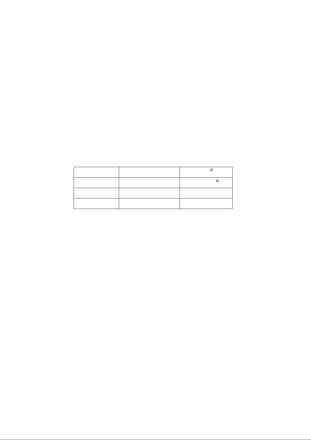
2.12 For the storage make sure to p ut i t i n a place where th e environment can b e c ontr ol l e d
so as to prevent the temperature a nd hu mi di t y from exceeding th e l imits as specifie d in
the manual. For prolonged storage, it is necessary to house it in an anti-moisture bag
and put them altogether in one place. The ambient conditions are tabulated as follows:
Temperature Scope for operation
Scope for storage
humidity Scope for operation
Scope for storage
0—+50 C
-20—+60 C
20%—85%
10%—90%
2.13 Display of a fix ed pictur e for a long time may r esult in ap pear ance o f picture residu e o n
the screen, as commmonly called “ghost shadow”. The extent of the residual picture
varies with the maker of LCD screen. This phenonmenon doesn’t represent failure.
This “ghost shadow” may remain in the picture for a period of time (several
minutes).But when operating it please avoid displaying still picture in high brightness
for a long time.
3. Points for attention during installation
3.1 The front panel of LCD screen is of glass. Wheng installing it p lease make sure to put it
in place.
3.2 For service or instatallation it’s necessary to use specified screw lest it should damage
the screen.
3.3 Be sure to take anti dust measures. Any foreign substance that happens to fall down
between the screen and the glass will affect the receiving and viewing effect
3.4 When dismantling or mou nting the pr otectiv e partition pl ate that i s used for anti v ibrati on
and insulation please take care to keep it in intactness so as to avoid hidden trouble.
3.5 Be sure to protect the cabinet from damage or scratch during service, dismantling or
mounting.
Instructions on adjusting and testing
1. Flow process of adjustment and calibration
For flow process of adjustment and calibration, see Fig. 1
2
Page 4

Fig. 1
Check if N4, N20, N303, N302 has been
Connect to central signal source, check if various TV functions
(station skipping, modulate quantity control etc), check if the output
Input TV/AV/ S terminal/SCART/VGA signals, select
MONITOR, check if the function of SCART OUTPUT
Input VGA signal and check if display is normal in the state
of PC and various functions (analog quantity control,
line/field center etc.)
Produce main board, TV board on line
Adjust TV board
Combined test for general assembly
of earphone and speaker are normal
Input SCART/AV/S signal, check different
functions of SCART/AV/S terminals
separately SCART OUTPUT state to be TV or
Check accessories and then packing
FLASH written.
Check main board
Check TV board
is normal
Figure 1. Flow process of adjustment and calibration
3
Page 5

2.Adjustment and calibration deacription
2.1 Method to enter factory menu
Push MUTE-MENU-OK-SLEEP key in turn at the interval of 1 second
2.2 Adjustment and calibration equipment
Digital multi-meter, signal generator (with SCART/RGB signal output), oscillograph,
PC set ( preset the program of flash written), K7253(VGA signal generator), CA210
(LCD white balancer) DVD displayer, TV with SCART connector 1 set, IF signal
generator
2.3 Written program
Writing the memory unit N4, N20, N303, N302
2.4 Main board adjustment and calibration
a) Main board X501 Connect infra-red receiving board (as per connect diagram),
insert the output plug of power supply adapter(FSP048-1AD101C for 15,
FSP060-1AD103 for 17,20’) into X1, when the indication lamp of infra-red receiving
board should be in red
b) Connect PC set. Run FLASH N20 upgrade program, push POWER key on the
remote control set, when the indication lamp of infra-red receiving board should be in
red
c) About 4 minutes later, indication lamp of infra-red receiving board turns to
yellow/blue (LC-15H4 S/17H4 S/20H4 S), measure L102 PIN2 5.0 V,L107 PIN2 3.3
V, N10 PIN2 1.8 V, and N12 PIN2 1.8 V.
d) Write DDC program
2.4 TV board adjustment
2.5.1 IF adjustment
a) Input DV 5V into TP2, input 12V to TP6, Input 5V to TP4 and input 0V to TP5,
monitor voltage o f TP3, input 38. 9 MHz sig nal to TP1, and use a non -i nductance screw
driver to adjust IFT L207 so that TP3 voltage is 1.65V
b) Input DC 5V into TP2, input 12V to TP6, Input 0V to TP4 and input 5V to TP5,
monitor voltage of TP3, input 33.9 MHz signal to TP1, adjust potential meter RP202 to
set TP3 voltage to 1.65V.
c) Connect IF line of tuner, control line L and L’: three disconnected points in total.
2.5.2 Connection of the complete set
Connect main board, TV boar d, in fra-red rec eivi ng board (as per co nnect diagr am),
push POWER key on the remoter control set, when the indication lamp of infra-red
receiving board is in yellow/blue (LC-15H4 S/17H4 S/20H4 S),measure PIN2 of
N301to be 3.3 V on TV board, one end of SMT conductance L632 to be 5V, another
end of SMT conductance L632 to be 12V.
2.5.3 AGC Adjustment
Receive D-8 signal of 60 db , measur e the v oltag e o f positiv e pole o f D201 w i th DC
potential meter.
Adjust potential meter RP201 to make reading of potential meter just decrease below
4.0V.Input 100db from antenna, the picture should not appear non-synchronized and
distorted, input weak signal of 35 dB--40 dB, color should not disappear, picture
synchronizes, normal sound.
2.6 Wht balance adjustment ( Use LCD special white balancer CA210,K7253 signal
4
Page 6
generator)
a) Assembly complete set;
b) Enter factory menu, realize “PW1306 reset”, adjust background brightness to be
maximum;
c) Quit factory menu, enter D_SUB channel, input 60 HZ “pane
signal”(C_Hat_16x12(W)),to VGA terminal. Thus the discrimination rate should be the
best discrimination rate for the LCD screen, see table 1, enter user menu, adjust
brightness to 50, contrast to 50 adjust line center, field and center to make the picture
location to be correct.
d) Input “16 grades of grey degree” signal (Gray(H)-16), enter factory menu, realize
AQC calibration”
e) Quit factory menu, input “8 grey degree” signal ( Gray(H)-8 ), enter user menu,
adjust brightness and contrast, measure sixth degree with CA-210, make Y to 180
2
cd/m
, enter factory menu, ,fix green to be 50,adjust red, blue to make
x=284,y=299.(This procedure may not be taken now)
f) Enter AV mode, input “8 grey degree” signal, adjust tint to 0, adjust brightness and
contrast, measure sixth degree with CA-210, make Y to 180 cd/m
2
, enter factory
menu, ,fix green to be 50,adjust red, blue to make x=284,y=299.
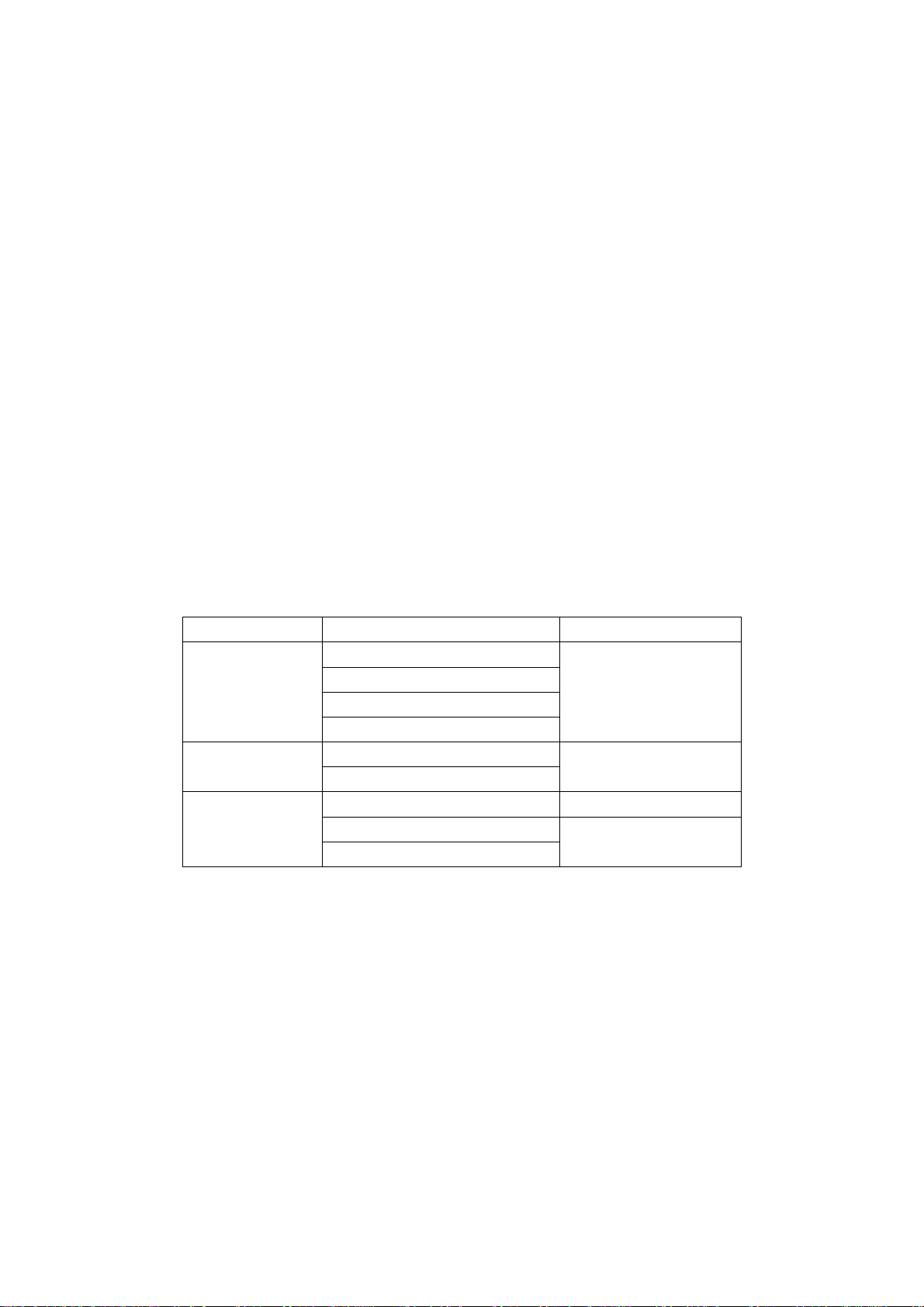
Notice: For the best discrimination rate of LCD screen, see table 1.
Table 1:LCD resolution of best
Screen size Factory
Samsung
15”
17”
20”
AU
Sanyo
CPT
Samsung
AU
AU 800x600
Chimei
LG
LCD resolution of best
1024x768
1280x1024
640x480
3. Functional Inspection
3.1. ITV connector
Connect central signal source to RF connector. Enter the search menu--auto
search, check if there is station skipping. Check semi-auto search, see if micro
adjustment is normal, check output of earphone and speaker is normal, picture is
normal.
3.2 SCART/AV/S inut termianl
Separately input signal of SCART/AV/S terminal, check picture and sound if they
are normal.
3.3 AUDIO OUT termianl/ VIDEO OUT terminal
5
Page 7
Input signal separately to TV/SCART/AV/S terminal, connect AUDIO/VIDEO OUT
terminal to monitor, check the output sound of AUDIO OUT is normal, and output
picture of VIDEO OUT is normal. (LC-20H3 S/20H4 S)
3.4 SCART connector
3.4.1 Inspection of connector content of SCART OUTPUT
Input signal to different TV/SCART/AV/S/VGA terminals, connect SCART
connector to TV as monitor. Select SCAR T OUTPU T item of menu t o TV, check out put
of picture and sound if they are all TV picture and sound, and if they are normal; select
SCART OUTPUT item of menu to MINITOR, check picture and sound if they are
current picture and sound of signal (Under VGA state, switch to formal VGA) and
check if they are normal.
(* Note: For the TV sets produced in the initial stage the picture is colorless for the signal
output from A V O UTPUT, SCART OUTPUT under S-term inal)
3.4.2 inspection of special function of SCART INPUT
a) After power supply on, input SCART to signal generator, the set should
automatically switch to AV1or AV1 RGB state.
b) SCART signal generator outputs CVBS signal (color bar + multi-wave group ),
observe if the picture of the set is normal. The normal screen should be AV1: change
SCART signal to RGB format, the normal screen should be AV1 RGB.
c) Disconnect SCART signal, the set could come back to current TV state.
(Note: This special functi on i s not applicable to VGA)
3.5 VGA connector
Input VGA signal (K 7253 sig nal g enerat or) , in put di fferent VGA form at sig nal lis ted
in table 2, after completion of the auto calibration, check the picture and sound if they
are normal. If there is interfere in picture, push the auto-adjustment key on the remote
control set one more time, check if the display is normal.
3.6 Factory preset
Enter factory menu, perform factory presetting under TV state.
3.7 Packing for factory outgoing
Check accessory, then pack.
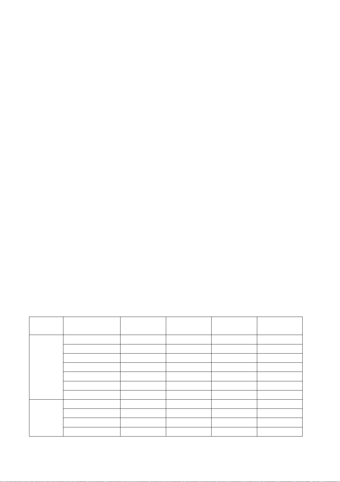
Table 2.VGA format signal
screen size resolution
640x480 @ 60 25.175 31.469 59.900
720x400 @ 70 28.322 31.469 70.086
800x600 @ 60 40.000 37.879 60.317
15”
17”
1024x768 @ 60 65.000 48.363 60.004
640x480 @ 75 31.500 37.500 75.000
800x600 @ 75 49.500 46.875 75.000
1024x768 @ 75 78.750 60.023 75.029
640x480 @ 60 25.175 31.469 59.900
720x400 @ 70 28.322 31.469 70.086
800x600 @ 60 40.000 37.879 60.317
1024x768 @ 60 65.000 48.363 60.004
Image clock
(MHz)
H-SYNC
(kHz)
V-SYNC
(Hz)
remark
6
Page 8
640x480 @ 75 31.500 37.500 75.000
800x600 @ 75 49.500 46.875 75.000
1024x768 @ 75 78.750 60.023 75.029
1280x1024@60 108 63.981 60.2
1280x1024@75 135 79.976 75.025
640x480 @ 60 25.175 31.469 59.900
720x400 @ 70 28.322 31.469 70.086
800x600 @ 60 40.000 37.879 60.317
20”
640x480 @ 75 31.500 37.500 75.000
800x600 @ 75 49.500 46.875 75.000
CMOscreen
nonsupport
CMOscreen
nonsupport
Trouble shooting
Before servicing please check to find the possible causes of the troubles according to the
table below.
1.Antenna:
Picture is out of focus or jumping Bad status in signal receiving
Maybe broadcast signal itself is not good
Check if the outdoor antenna is disconnected.
Check if the antenna is correctly oriented.
Fringe in picture Check if the antenna is correctly oriented.
Maybe there is electric wave r eflect ed from hilltop or building.
Picture is interfered by stripe
shaped bright spots
There appear streaks or light color
on the screen
Possibly due to interference from automobile, train, high
voltage transmission line, neon lamp etc.
Maybe there is interference between antenna and power
supply line. Please try to separate them in a longer distance.
Check if interfered by other equipment and if interfered
possibly by the equipment like transmitting antenna, non
professional radio station and cellular phone.
7
Page 9
2.TV set:
Symptoms Possible cause
Unable to switch the power on Check to see if the power plug has been inserted properly into
the socket.
No picture and sound Check to see if the po wer supply of liquid crystal TV has been
switched on. (as ca n be indic ated by th e red LED at the front
of the TV set)
See if it’s receiving the sig nal that is transmitted from other
source than the station
Check if it’s connected to the wrong term inal or if the input
mode is correct.
Check if the signal cab le co nnec ti on b et we en vid eo f r equency
source and the liquid crystal TV set is correct.
Deterioration of color phas e or c olor
tone
Screen position or size is not proper Check is the screen position and size is correctly set up.
Picture is twisted and deformed Check to see if the picture-frame ratio is properly set up.
Picture color changed or colorless Check the “Component” or ”RGB”settings of the liqu id c r ystal
Picture too bright and there is
distortion in the brightest area
Picture is whitish or too bri ght in the
darkest area of the picture
No picture or signa l produced from
the displayer if “XXX in
search”appears.
There appears an indication “outside the receivable scope)
Remote control cannot work
properly
No picture and sound, but only
hash.
Check if all the picture setups have been corrected.
TV set and m ake proper adjus tment according to the signal
types.
Check if the contrast setting is too high.
Possibly the output quality of DVD broadcaster is set too high.
It maybe also due to improper terminal connection of the video
frequency signal in a certain position of the system.
Check if the setting for the brightness is too high
Possibly the brightness grade of DVD player(broadcaster)is
set too high.
Check if the cable is disconnected.
Check if it’s connected to the proper terminal or if the input
mode is correct.
Check if the TV se t can receive inpu t signal. T he signa l is not
correctly identified and VGA format is beyond the specified
scope.
Check if the batteries are installed in the reverse order.
Check if the battery is effective.
Check the distance or angle from the monitor.
Check if there is any obstr uct bet ween the rem ote contr ol and
the TV set.
Check if the remote control signal- receiving window is
exposed to strong fluorescence.
Check if the antenna cable is correctly connected, or i f it has
received the video signal correctly.
8
Page 10
Blur picture Check if the antenna cable is correctly connected.
Of if it has received the right video signal.
No sound Check if the “mute” audio frequency setting is selected.
Check if the sound volume is set to minimum.
Make sure the earphone is not connected.
Check if the cable connection is loose.
When playing VHS picture search
tape, there are lines at the top or
bottom of the picture.
When being played or in pause VHS picture search tape
sometimes can’t provide stable picture, which may lead to
incorrect display of the liquid crystal TVIn this case please
press “auto” key on the remote control so as to enable the
liquid crystal TV set to recheck the signal and then to
display correct picture signal
Method of softwar e upgrading
Steps of software upgrading are as follows:
1 Select a serial connection wire and a VGA connection wire and then connect them by
means of a patch panel;
2 Use a serial wire to connect the PC to the patch panel and set TV set to off state;
3 Open the software upgrade file holder and double click
FlashUpgraderNT(use under window 2000/XP/NT)
FlashUpgrader(use under window 98),
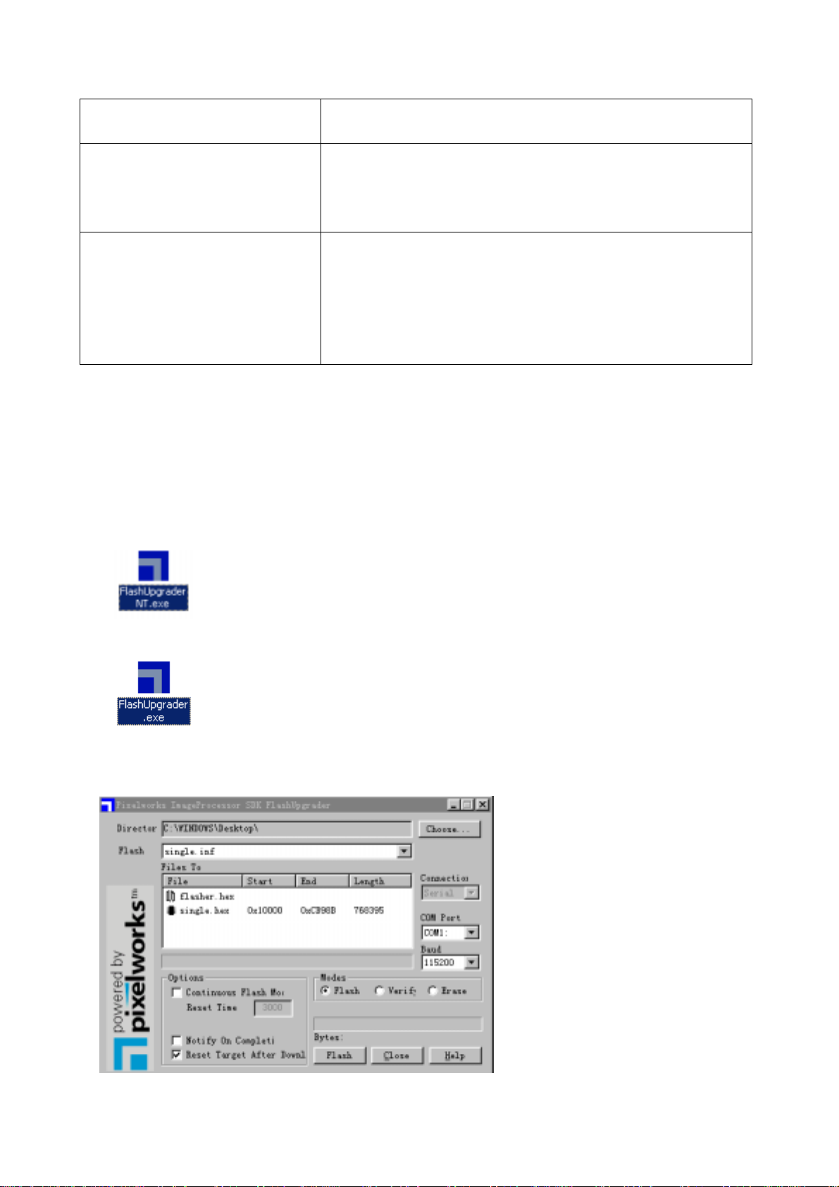
The following interfaces will show up after running the program:
9
Page 11

Based on the computer features, set up t he serial port(COM Port). Select corresponding serial port (if
it’s unable to FLASH WRITE, change to another port). Baud is selected to be 115200. Then select
Reset Target After Download. Click FLASH pushbutton, it’s ready to run. For other settings, please
refer to the Fig. Above (already defaulted by the system, normally no need t o change).
4 Switch on TV set the FLASH write program begins to run;
5 After FLASH write is over, push button “cancel” will become flash. Then shut the main power supply
and it’s OK just switch it on again.
Note: Do not shut the power off or turn the TV set on during the FLASH write. Otherwise it may
lead to no way for flash to rewrite.
Simple introduction and work principle of LC15/17/20H3S
LC20H3 multi-media LCD TV broadcast receiver adopts LG 20.1 inch LCD display
screen as display unit. It has PAL/SECAM B/G,I,D K L L, color system receiving functions
and at the same time with AV input, S-VHS input, PC VGA connector and earphone output
and other signal connectors. The power supply is outer connection of 12V power supply
adaptor
LC15/17/20H3S multi-media LCD TV broadcast receiver consists of RF, video signal
board assy”, digit picture processing assy’.
RF signal produces picture IF signal and sou n d IF si g nal by tuner N201, throug h Vi deo
and Sound saw filter Z201, Z202, and the signals are sent to Video/Sound(VIF/SIF) multi
systems signal processor of N202 TDA4470 pin6,pin7,and pin1,pin2, for picture and sound
demodulation. The demodulated composite signal, after trapping, is selected by the switch
N202, and then output to N303 and ICVCT3833 for decoding.
The composite video signal is sent through foot 19 of ICN303VCT3833. After
processing there, it is output as analog RGB signal from Pin42, PIN43, PIN44 to digit
10
Page 12

picture processing assy’. The sound SIF signal is sent to foot 67 of ICN402 MSP3410G for
sound processing. The output signal from Pin28,Pin27 of N401MSP3410G is output to
sound amplification N404TDA7268(20”TPATP1517). After amplification, it is sent to
speaker.
Input signals to main board include RGB signals from RF, video signal assy’, VGA
signal from personal computer. The 2:1 switches ICN5 BA7657F of five routs select R,G,B
signals and then send them to main processor IC PW1306.
PW1306 is a main processing IC built-in type X86 CPU, with outer memory 8M
Flash(N20)and controls the whole system. The input signal from V-port and G-port is
subject to internal arithmetic process and then output in R,G,B of 24 bit TTL to sockets
JP3,JP4. Through connection line the signal is sent to LG LCD screen port for the
realization of the picture re-display.
Converter DS90C383A/DS90CF383A LVDS converts CMOS/TTL data of 28
digit(DRE<7:0>, DGE<7:0>, DBE<7:0>and LCD timing and control data, FPLINE,
FPFEAME, DRDY)to four groups of LVDS INFORMATION FLOW (Low voltage differential
signal), then send them to the plane displayer for display.
11
Page 13

BLOCK DIAGRAM
12
Page 14

IC BLOCK
1
2
3
4
5
6
7
8
9
10
11
12
24
23
22
21
20
19
18
17
16
15
14
13
1
2
1
2
1
2
1
2
1
2
DET
Logic
Syncsepa
Ground
Ground
Ground
Ground
V
CC
CTL (H: IN1, L: IN2)
Red 1 input
Green 1 input
Blue 1 input
Red 2 input
Green 2 input
Blue 2 input
VD 1 input VD 2 input
VD output
Blue output
Composite sync output
Composite video input (Sync on Green)
Green output
Red output
HD output
HD 2 input
HD 1 input
HD Sync signal detector
BA7657F / BA7657S
Page 15

Page 16

Page 17

PW130
DRGB (23:0)
DGRGB(23:0)
DVS, DHS,
DEN, DCLK
CS
D
A
RxDTxD
NMI
(1:0)
(15:0)
(19:1)
JTAG Debugger
UART
Interrupt
Controller
Time rs
Watchdog and
RAM Interface
Processor ROM/
16-Bi t
Micro pr ocessor
Seri al
2-Wire
Micropro cessor Bu s
OSD
Memory Out Bus
Color
Space
Expander
Color
Ta b le s
Lookup
and
OSD
Gain
Color
Matrix
Ti mi n g
Displa y
Generator
Internal Block Diagram
PW130 ImageProce ssor
PLL and
MCL K DCLK UCLK
XI XO
Oscillator
Scaler
IR
Decoder
Reset
Memory
Interface
Processor
PortA(7:0)
GPIO PW M
Buffer
Memory
Auto Image
Memory In Bus
Opti mi za ti on
PowerOn
Reset
RESET
Figure 1-1 ImageProcessor Block Diagram
Data
MUX
PORTD (7:0)
HSHSYNC,
VS
CLK
R
G
B
ADC
VIDEO
CLK
RGB
HS,VS
Color
Space
Converter
VPEN
VCL K
VYUV(7:0)
Sync
Pro cessing
SOG
Stripper
FILT PLL
SOGIN
VSYNC
A/ DClamp
AIN
R
A/ DClamp
G
A/ D
Clamp
AIN
AIN
B
Page 18

Page 19

Page 20

Page 21

TDA4470
Block Diagram
VIF
C
AGC
(optional)
15
C
BL
Offset
comp.
6
7
8
26
FPLL
AGC
(VIF)
Loop
filter
VIF amp
18
0°
90°
VCO
20
phase shift
Video det.
VCO
+
21
L’ switch
14
Control
AFC
Standard
12
13
19
22
AFC
switch
AFC
Video
Standard
switch
Tuner
Take over
point
SIF 2
SIF input
switch
SIF 1
C
AGC
11
10
27
28
23
Tuner
AGC
FM det.
SIF amp
3
1
2
5
AGC
(SIF)
AM det.
Figure 1. Block diagram
Supply
17
C
24
Intercarrier
(FM / NICAM)
25
4,9,16
95 10851
Ref
V
S
AF
(AM)
Page 22

V
VOLTAGE
VOLTAGE
S-video
R
L
HIGH
HIGH
R
Audio
L
MSP3420G
Page 23

Serial No. of Parts
15" 17" 20"
Sell area Europe Europe Europe America
LCD panel Samsung
335-15012-00
Back light board 667-L15H3-14 667-L17H3-14 667-L20H3-14A
High frequency board 667-L15H3S-55 667-L15H3-55 667-L20H3S-55
Main board 667-L15H3-01S 667-L20H3-01S
adapter 302-L1510-02 302-AD16A-02 302-AD16A-02
antetype 203-L15H30-02
Sell area Europe Europe Europe America
LCD panel AU335-15112-00 AU335-2000F-00
Back light board 667-L15H3-14A 667-L20H3-14A
High frequency board 667-L15H3S-55 667-L20H3S-55
Main board 667-L15H3-01BS 667-L20H3-01S
adapter 302-L1510-02 302-ADA6A-02
antetype 203-L15H30-03 203-L20H30-02
Samsung
335-17050-00
Chimei
335-2000F-00
Identification criteria for the bright spot and dark spot of the LCD screen
Category criteria
One single
Bright
spo
t
Dark
spots
Total defected point ≤8 ≤7 ≤5 ≤4 /
Notes:
1. Definition of defected point (bright spot, dark spot): It is identified as a defected point if its
2. Definition of bright spot: It is identified as a bright spot if it is bright in the state of dark field
3. Definition of dark spot: It is identified as a dark spot if it is dark in the state of white field and
4. Definition of two neighboring points: Defects of a group of picture elements(RB,RG,GB).
spot
2 neighboring
spots
Total No. ≤5 ≤2 ≤5 ≤2 ≤3
One single
spot
Two
neighboring
spots
Total No. ≤6 ≤7 ≤5 ≤4 ≤10
area exceeds 1/2 of a single picture element (R,G,B).
and its bright size remains unchanged
its dark size remains unchanged
15" 20" 22" 30" 40" 15" 20" 22" 30" 40"
≤5 ≤2 ≤5 ≤2 ≤3
≤2 ≤1 ≤2 ≤1 ≤1
≤6 ≤7 ≤5 ≤4 ≤10
≤2 ≤2 ≤2 ≤1 ≤5
Q’ty allowed Distance between two spots
≥15mm
≥15mm
≥10mm
≥5mm
22
Page 24

Troubleshooting guide
No raster
Does the logo appear on the screen
when turning on the set ?
Yes Yes Good
Check whether there is R.G.B
output at X601 on TV board.
No
Replace TV board.
No sound
No No
Check whether the adapter
supply 12V power to Digital Board.
Check U125965V. Check whether FUSE is melted.
Good
Check whether U18 pin 63
is high level.
No
Replace Digital board.
Check whether X101 is
properly inserted.
No
Replace adapter.
Check N8 pin 14, 15, 22, 23, 38,
39, 46,47 (these pins should
have 12V power supply)
Yes
Check N8 pin3, pin 5's input signal.
Yes
Check whether N8 pin 4, 27, 28 are
normal. Pin 4 should be 2.43V,
pin 27 should be 1.46V and
pin 28 should be triangle wave.
No
Replace N8.
No
Check L302, X604 pin 5 and pin 6.
No No
Check N6 pin 5 and
pin 8 signal.
Yes
Check N8's welding
condition.
23
Check N5 pin 27
and pin 28 signal.
No
Check N5 pin 67 signal.
No
Check whether U1 pin 11
have output waveform.
Page 25

TV board troubleshooting
No picture but have raster.
Measure the waveform of
R.G.B Hors, Vers at X7.
No
Check whether N1 has
5V power supply.
Yes
Measure N1 pin 33, pin 35
waveform.
Yes
Measure N1 pin 42, pin 44
waveform.
Yes
Check V105-V107's
output waveform.
No
No
Check whether X9 pin 1, pin 2 have
No
5V power input.
Replace N2
No
Replace V105-V17.
No
Replace N1
24
Page 26

LC15H3S-01
Page 27

LC15H3S-02
Page 28

LC15H3S-03
Page 29

LC17H3S
Page 30

LC20H3S-01
Page 31

LC20H3S-02
 Loading...