

Page 1
LCD TELEVISION
LC17H2
Page 2

CONTENTS
Safety instructions………………………………………………………………………..…
Adjustment instructions …………………………….…….…………………………….…
Trouble shooting ……………………………………………………….……………………
Method of software upgrading……………………………………………………….………
Working principle analysis…………………………………………. ………………………….
Block diagram…………………………………………………..……………………………
Main IC block diagram………………………………………………………………….……..
Wiring diagram ……………………………………………………………..……………....
Main assembly……………………………………………………………………………..…
Identification criteria for the bright spot and dark spot of the LCD screen………..….
Troubleshooting charts………………………………………………………………..……
Schematic diagram ……………………………………………………………………..…
1
2
6
7
9
10
11
16
17
17
18
21
Page 3

Attention: This service manual is only for service personnel to take reference with. Before
servicing please read the following points carefully.
Safety instructions
1. Instructions
Be sure to switch off the power supply before replacing or welding any components or
inserting/plugging in connection wire Anti static measures to be taken (throughout the entire
production process!):
a) Do not touch here and there by hand at will;
b) Be sure to use anti static electric iron;
c) It’s a must for the welder to wear anti static gloves.
Please refer to the detailed list before replacing components that have special safety requirements.
Do not change the specs and type at will.
2. Points for attention in servicing of LCD
2.1 Screens are different from one model to another and therefore not interchangeable. Be sure to
use the screen of the original model for replacement.
2.2 The operation voltage of LCD screen is 700-825V. Be sure to take proper measures in
protecting yourself and the machine when testing the system in the course of normal operation or
right after the power is switched off. Please do not touch the circuit or the metal part of the module
that is in operation mode. Relevant operation is possible only one minute after the power is
switched off.
2.3 Do not use any adapter that is not identical with the TV set. Otherwise it will cause fire or
damage to the set.
2.4 Never operate the set or do any installation work in bad environment such as wet bathroom,
laundry, kitchen, or nearby fire source, heating equipment and devices or exposure to sunlight etc.
Otherwise bad effect will result.
2.5 If any foreign substance such as water, liquid, metal slices or other matters happens to fall into
the module, be sure to cut the power off immediately and do not move anything on the module lest it
should cause fire or electric shock due to contact with the high voltage or short circuit.
2.6 Should there be smoke, abnormal smell or sound from the module, please shut the power off at
once. Likewise, if the screen is not working after the power is on or in the course of operation, the
power must be cut off immediately and no more operation is allowed under the same condition.
2.7 Do not pull out or plug in the connection wire when the module is in operation or just after the
power is off because in this case relatively high voltage still remains in the capacitor of the driving
circuit. Please wait at least one minute before the pulling out or plugging in the connection wire.
2.8 When operating or installing LCD please don’t subject the LCD components to bending, twisting
or extrusion, collision lest mishap should result.
2.9 As most of the circuitry in LCD TV set is composed of CMOS integrated circuits, it’s necessary
to pay attention to anti statics. Before servicing LCD TV make sure to take anti static measure and
ensure full grounding for all the parts that have to be grounded.
2.10 There are lots of connection wires between parts behind the LCD screen. When servicing or
moving the set please take care not to touch or scratch them. Once they are damaged the screen
1
Page 4
would be unable to work and no way to get it repaired.
2.11 Special care must be taken in transporting or handling it. Exquisite shock vibration may lead to
breakage of screen glass or damage to driving circuit. Therefore it must be packed in a strong case
before the transportation or handling.
2.12 For the storage make sure to put it in a place where the environment can be controlled so as to
prevent the temperature and humidity from exceeding the limits as specified in the manual. For
prolonged storage, it is necessary to house it in an anti-moisture bag and put them altogether in one
place. The ambient conditions are tabulated as follows:
Temperature Scope for operation 0 ~ +50 oC
Scope for storage -20 ~ +60 oC
Humidity Scope for operation 20% ~ 85%
Scope for storage 10% ~ 90%
2.13 Display of a fixed picture for a long time may result in appearance of picture residue on the
screen, as commonly called “ghost shadow”. The extent of the residual picture varies with the
maker of LCD screen. This phenomenon doesn’t represent failure. This “ghost shadow” may remain
in the picture for a period of time (several minutes). But when operating it please avoid displaying
still picture in high brightness for a long time.
3. Points for attention during installation
3.1 The front panel of LCD screen is of glass. When installing it please make sure to put it in place.
3.2 For service or installation it’s necessary to use specified screw lest it should damage the screen.
3.3 Be sure to take anti dust measures. Any foreign substance that happens to fall down between
the screen and the glass will affect the receiving and viewing effect
3.4 When dismantling or mounting the protective partition plate that is used for anti vibration and
insulation please take care to keep it in intactness so as to avoid hidden trouble.
3.5 Be sure to protect the cabinet from damage or scratch during service, dismantling or mounting.
Adjusting instructions
1. Test equipment
Digital multimeter
5515 signal generator
K-7253 (VGA and YPrPb signal generator)
CA210 (LCD White balancer)
2
Page 5
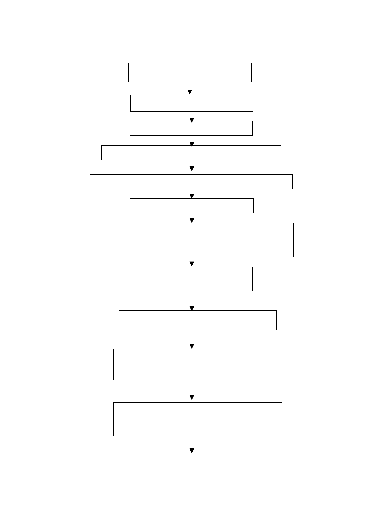
2. The alignment flow chart (see below figure)
r
Check main board, TV board and power supply board
Check if output 12V and 18V of the power supply board is normal
Connect to central signal source, check if various TV functions (station
skipping, modulate quantity control etc) and the output of earphone
Check if N4, N20, N303 and N302 has
been FLASH written.
Produce main board and TV board
Testing TV board
Combined test for general assembly
and speaker are normal
Input AV/S terminal signal, check
different functions of AV/S terminals
Input TV, S terminal and AV signals, check if AV
OUT is normal.
Input VGA signal and check if display is normal in
the state of PC and various functions (analog
quantity control, line/field center etc.)
Input YPrPb signal, check if the display is normal unde
PC and various functions (analog control, line/field
center etc.)
Check accessories and then packing
3
Page 6

3. Flash writing programs
Flash writes memory N4, N20, N303 and N302.
4. Adjustment of power supply board
Connect the small power supply board to the power supply board (connect 12V of the small power
supply board to X905 of the power supply board, connect 18V of the small power supply board to
X906 of the power supply board), then turn on it, check if output is normal.
5. Adjustment of main board
a. Connect the main board X501 to infrared receiving board, connect X904 of the power supply
board to X1 of the main board, now the indication lamp of the infrared receiving board is red.
b. Connect PC, upgrade the program of FLASH N20, push the POWER key on the remote control
set. Now the indication lamp of the infrared receiving board is red.
c. About 4 minutes later the indication lamp of the infrared receiving board turns blue or yellow.
Measure L102 PIN2 to be 5.0 V, measure L107 PIN2 to be 3.3 V.
d. Flash write DDC program.
6. Adjustment of TV board
Connect main board, TV board and infrared receiving board and press the POWER button, now the
indication lamp of the infrared receiving board is blue or yellow. Measure N301 PIN2 of TV board to
be 3.3 V, one terminal of inductor L630 to be 5 V and one terminal of inductor L632 to be 12 V
7.Adjustment of white balance (using the white balancer CA210 and K7253 signal generator
specialized for LCD)
a. Install the whole TV set
b. Enter the factory menu and perform “PW1306 reset”
c. Exit from the factory menu. Press “ source” button and enter YPbPr.
d. Input YPbPr signal: 640x480p 60Hz (K7253).
e. Enter the user menu. Set the brightness to 50 and contrast to 50. Press “factory” button to enter
the factory menu, perform “ADC calibration”, input signals of “black field”(EMPT),”white field”(White(100%))”fully red”(Full_Magenta) respectively and then calibrate three times.
f. Input signal of “eight grade gray”(Gray (H)-8). Use CA-210 to measure the third grade and adjust
the brightness and contrast so that Y is around 180. Enter factory menu and adjust the green color
temperature and blue color temperature so that x=270,y=283(red color temperature is constant
as128).
g. Exit from the factory menu and enter RGB channel. Input 60Hz “pane signal ” (C_Hat_16x12(W))
through port VGA. Enter the user menu and adjust the brightness to 50 and contrast to 50. Adjust
the line center and the field center so that the picture is correctly positioned.
h. Input signal of “16 gray grades” (Gray(H)-16). Enter the factory menu and perform “calibration of
ADC”.
i. Exit from the factory menu, input the signal of “eight grade gray” (Gray(H)-8 ) and enter the user
menu. Adjust the brightness and contrast. Use CA-210 to measure the sixth grade so that Y is
around 180. Enter the factory menu and adjust the green color temperature and blue color
temperature so that x=284,y=299(red color temperature is constant as128).
j. Enter the factory menu and adjust the green color temperature and blue color temperature so that
x=284,y=299.
Notice: For the best discrimination rate of LCD screen, see table 1.
Table 1:LCD resolution of best
4
Page 7
Screen size Factory
LCD resolution of
best
Samsung
17”
FUJITSU
1280x1024
LG
PHILIPS
8.Performance check
a). TV Interfaces
Connect RF port to central signal source. Enter station search menu - auto station search. After
system adjustment is over, check if there is any station missing and then check semi-auto station
search.
Check if fine-tuning is normal.
Check if the output of earphone or loudspeaker is normal and if the picture is normal.
b). AV/S Terminals
Connect to access the signal of AV/S terminals separately and check if the picture or sound is
normal.
c). AV OUT Terminal
Input the signals separately in the status of TV/AV/S terminal. Connect AV OUT terminal to monitor
and check if the output picture and sound from AV OUT is normal. (Note: In the status of S terminal,
the output picture from AV OUT is colorless.)
d). VGA Interface
Input VGA signal (K7253 signal generator). Separately input the four types of VGA format signals as
listed in Table 2. Wait till auto calibration is over. Then check if the picture and sound is normal. If
there has been interference to the picture then press the auto set key on the remote control once
again and check if the display is normal.
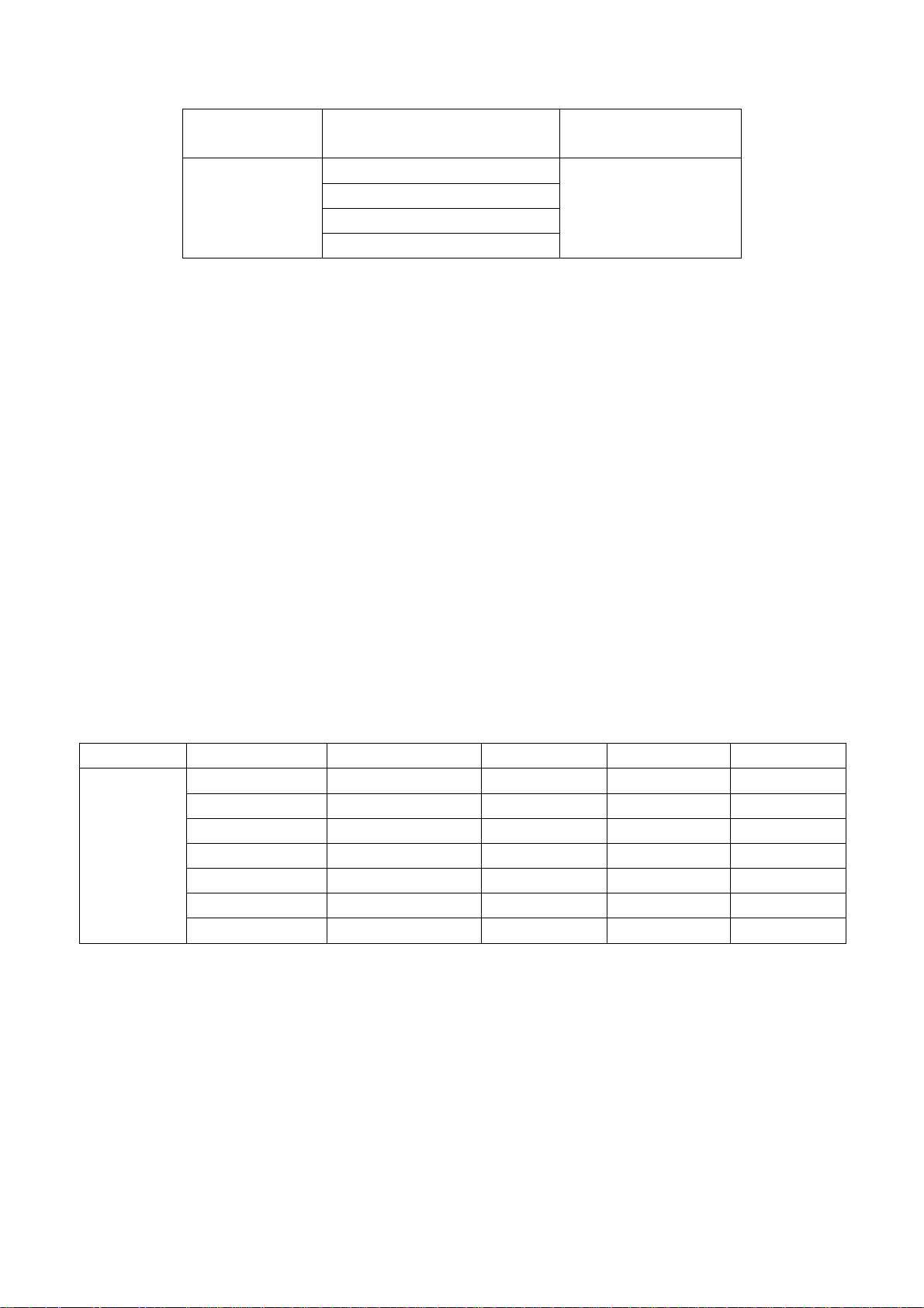
Table 2.VGA format signal
screen size resolution Image clock(MHz) H-SYNC(kHz) V-SYNC(Hz) remark
25.175 31.469 59.900
28.322 31.469 70.086
40.000 37.879 60.317
65.000 48.363 60.004
31.500 37.861 70.000
50.000 48.077 70.000
75.000 56.476 70.000
17”
640x480 @ 60
720x400 @ 70
800x600 @ 60
1024x768 @ 60
640x480 @ 70
800x600 @ 70
1024x768 @ 70
e). YprPb Interface
Connect to access YprPb signal (K7253 signal generator). Separately input the five types of YprPb
format signals -- 480P/50 Hz, 480P/60 Hz, 720P/60 Hz, 1080I/50 Hz, 1080I/60 Hz and check if the
picture and sound is normal after auto calibration is over.
Connect to access YprPb signal (DVD signal generator). Input the signals -- 480I/50Hz, 480I/60 Hz
separately and check if the picture and sound is normal.
9. Preset ex-works
In the status of TV enter the factory menu by pushing the factory key and then perform presetting.
10. Ex-works packing
Check accessories and then pack them in box.
5
Page 8
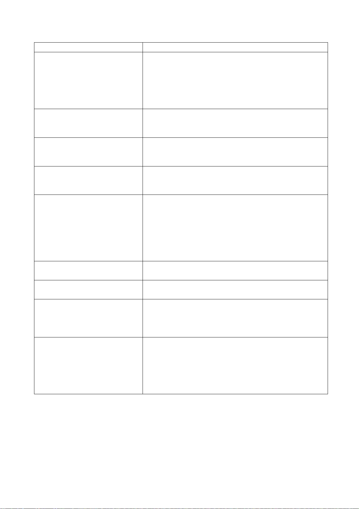
Trouble shooting
Before servicing please check to find the possible causes of the troubles according to the table
below.
1.Antenna (signal):
Picture is out of focus or jumping Bad status in signal receiving
Poor signal
Check if there are failures with the electrical connector or
the antenna.
Check if the antenna is properly connected.
Fringe in picture Check if the antenna is correctly oriented.
Maybe there is electric wave reflected from hilltop or
building.
Picture is interfered by stripe
shaped bright spots
There appear streaks or light color
on the screen
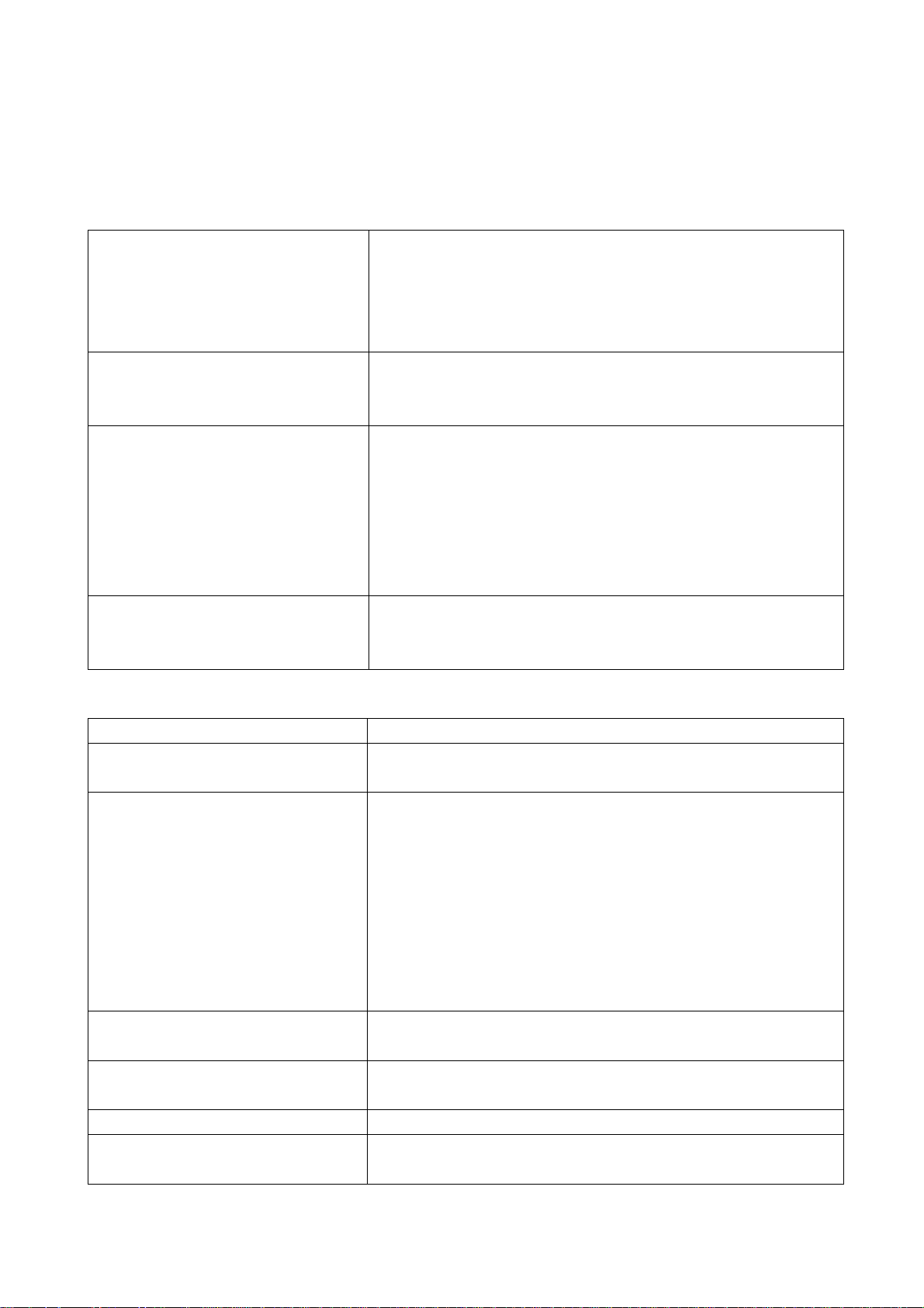
2.TV set:
Symptoms Possible cause
Unable to switch the power on Check to see if the power plug has been inserted
No picture and sound Check to see if the power supply of liquid crystal TV has
Deterioration of color phase or
color tone
Screen position or size is not
proper
Picture is twisted and deformed Check to see if the picture-frame ratio is properly set up.
Picture color changed or colorless Check the “Component” or “RGB” settings of the liquid
Possibly due to interference from automobile, train, high
voltage transmission line, neon lamp etc.
Maybe there is interference between antenna and power
supply line. Please try to separate them in a longer
distance.
Maybe the shielded-layer of signal wire is not connected
properly to the connector.
Check if interfered by other equipment and if interfered
possibly by the equipment like transmitting antenna,
non-professional radio station and cellular phone.
properly into the socket.
been switched on. (As can be indicated by the red LED
at the front of the TV set)
See if it’s receiving the signal that is transmitted from
other source than the station
Check if it’s connected to the wrong terminal or if the
input mode is correct.
Check if the signal cable connection between video
frequency source and the liquid crystal TV set is correct.
Check if all the picture setups have been corrected.
Check is the screen position and size is correctly set up.
crystal TV set and make proper adjustment according to
6
Page 9
the signal types.
Picture too bright and there is
distortion in the brightest area
Picture is whitish or too bright in
the darkest area of the picture
No picture or signal produced from
the displayer if “XXX in search”
appears.
There appears an indication “outside the receivable scope)
Remote control cannot work
properly
No picture and sound, but only
hash.
Blur picture Check if the antenna cable is correctly connected.
No sound Check if the “mute” audio frequency setting is selected.
When playing VHS picture search
tape, there are lines at the top or
bottom of the picture.
Check if the contrast setting is too high.
Possibly the output quality of DVD broadcaster is set too
high.
It maybe also due to improper terminal connection of the
video frequency signal in a certain position of the
system.
Check if the setting for the brightness is too high
Possibly the brightness grade of DVD player
(broadcaster) is set too high.
Check if the cable is disconnected.
Check if it’s connected to the proper terminal or if the
input mode is correct.
Check if the TV set can receive input signal. The signal is
not correctly identified and VGA format is beyond the
specified scope.
Check if the batteries are installed in the reverse order.
Check if the battery is effective.
Check the distance or angle from the monitor.
Check if there is any obstruct between the remote control
and the TV set.
Check if the remote control signal- receiving window is
exposed to strong fluorescence.
Check if the antenna cable is correctly connected, or if it
has received the video signal correctly.
Of if it has received the right video signal.
Check if the sound volume is set to minimum.
Make sure the earphone is not connected.
Check if the cable connection is loose.
When being played or in pause VHS picture search tape
sometimes can’t provide stable picture, which may lead
to incorrect display of the liquid crystal TV, In this case
please press “auto” key on the remote control so as to
enable the liquid crystal TV set to recheck the signal and
then to display correct picture signal
Method of software upgr adi ng
Steps of software upgrading are as follows:
1. Select a serial connection wire and a VGA connection wire and then connect them by means of a
patch panel;
2. Use a serial wire to connect the PC to the patch panel and set TV set to off state;
7
Page 10

Open the software upgrade file holder and double click
FlashUpgraderNT (use under window 2000/XP/NT)
FlashUpgrader (use under window 98),
The following interfaces will show up after running the program:
Based on the computer features, set up the serial port (COM Port). Select corresponding serial port
(if it’s unable to FLASH WRITE, change to another port). Baud is selected to be 115200. Then
select Reset Target After Download. Click FLASH pushbutton, it’s ready to run. For other settings,
please refer to the Fig. Above (already defaulted by the system, normally no need to change).
Switch on TV set the FLASH write program begins to run;
After FLASH write is over, push button “cancel” will become flash. Then shut the main power supply
8
Page 11

and it’s OK just switch it on again.
Note: Do not shut the power off or turn the TV set on during t he FLASH write. Otherwise it
may lead to no way for flash to rewrite.
Working principle analysis
Multi-media liquid crystal TV broadcast and receiving set adopts liquid crystal display screen, which
is provided with NTSC color system receiving function in addition to AV input, S-VHS input, high
definition signal port for component YPrPb/YcbCr, PC VGA port, earphone output and other signal
ports. For power supply an externally connected power adaptor is provided.
The circuitry of LC20H8 is composed of RF module board, video signal board, digital signal picture
processor and AC-DC transformer, and DC-DC circuit board.
The working process is as follows. The radio frequency signal undergoes an integrated tuner
TUNER1 before a color full video signal is generated. This video signal then enters analog board
decoder IC N303 VCT3833 Pin19 where it is processed and it’s output as analog signals R, G, B
through Pin42, PIN43, and PIN44. Audio frequency signal is processed with sound in IC N401
MSP3420G and then output through MSP3420G Pin28, Pin27 to SRS for surround sound
processing in IC N403 M62494E. Finally it is subject to power amplification in IC N404 TDA1517
before it is output to speaker.
VGA signal/high definition signal is input to personal computer through the main board. The signal
selected by Y/Pb/Pr through 5 way 1/2 switches IC(N1 BA7657F)is subject to reselection together
with signal TVRAIN, TVGAIN, TVBAIN through 5 way 1/2 switches IC(N5 BA7657F). Finally signals
R, G, B are selected and sent to the main processing chip IC N19 PW1306.
IC N19 PW1306 is a built-in X86 CPU of the main processing IC, externally connected by 8M Flash
(N20) memory to control the whole system. The input signal of V-port and G-port is subject to
internal arithmetic processing and then output as R, G, B signals with electric level of 24 bit TTL to
sockets JP3 and JP4, where through connection wires the signals are sent to the port of LG liquid
crystal screen and for the realization of picture reproduction.
9
Page 12
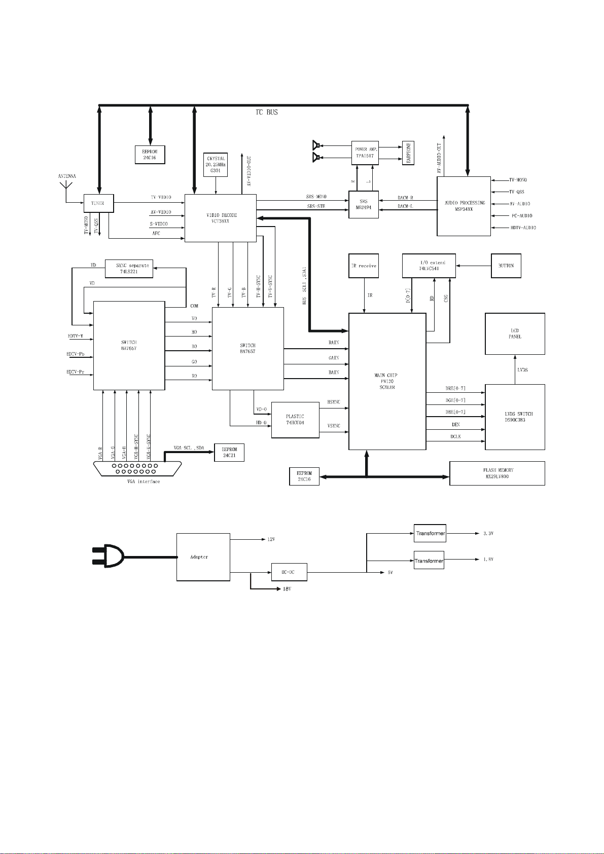
Block diagram
10
Page 13

Main IC block diagram
1.TPA1517
2.DS90C383A/DS90CF383A
11
Page 14

3.VCT 38xx A/B
SGND
VRT
VSUP AF
GNDAF
VCT 38xxA/B
VSUPD
GNDD
VERT
2 2
EW
HOUT
PROT
HFLB
SENSE
RSW2GNDM
XREF
VRD
VIN
CIN
VOUT
4
3
Video
Front-end
Video
TPU
24 kB
24 kB ROM
3kB
3kB
OSD
OSD RAM
16 kB
Te xt
RAM
Comb
Filter
DMA
31
Color
Decoder
BE
RDY
Panorama
Scaler
8
CPU
1kB
CPU RAM
96 kB
CPU ROM
2
IC
MSync
Color, Prio
VSync
Display
Processor
Pict.Improv
2
IC Master
8-bit PWM
14-bit PWM
15:1 Mux
10-bit ADC
2 Timer
2 CapCom
W atchdog
24 IO Ports
Video
Back-end
Audio
Reset
Logic
Clock
Oscillator
3
4
2
3
2
RGBOUT
SVM
RGBIN
VSUP AB
GNDAB
AOUT
AIN
2
IC
RESQ
TEST
XTAL1
XTAL2
ADB, DB, CB
12
GNDS
VSUPS
VSUPP1
GNDP1
CLK20
12
Page 15

4.MSP 34x0G
13
Page 16

5.BA7657F / BA7657S
Red 1 input
HD Sync signal detector
Green 1 input
Ground
Blue 1 input
Ground
Red 2 input
Ground
Green 2 input
Ground
1
1
2
3
4
5
6
7
8
9
10
1
2
1
2
1
2
2
DET
Syncsepa
Logic
HD 1 input
24
HD 2 input
23
HD output
22
Red output
21
CC
V
20
Green output
19
Composite video input (Sync on Green )
18
Composite sync output
17
CTL (H: IN1, L: IN2)
16
Blue output
15
Blue 2 input
VD 1 input VD 2 input
11
12
1
2
14
13
VD output
14
Page 17

6.PW1306
DERGB (23:0 )
DORGB(23:0)
DVS, DHS,
DEN, DCLK
CS
D
A
RxDTxD
NMI
(1:0)
(15:0)
(19:1)
PortA & D (7:0)
Interrupt
Processor ROM/
16-Bit
2-Wire
IR
UART
Controller
RAM Interface
Microprocessor
Serial
Decoder
GPIO PWM
Color
Space
Timers
Watchdog and
Color
Looku p
Tim ing
Dis play
Expand e r
Tables
Generator
Internal Block Diagram
PW1306 Video ImageProcessor
and
OSD
Gain
Mi c roproces s or Bus
OSD
Memory Out Bus
Mem ory
Inter face
Processor
Buffe r
Mem ory
Memor y I n Bu s
Scaling &
Color
Matrix
Video
Enhancem ent
Auto
Image
CSC
MCLK DCLK UCLK
Reset
PLL and
Pow erOn
XI XO
Oscillator
RESET
Res e t
HSHSYNC,
VS
CLK
ADC
A/DClamp
A/DClamp
A/DClamp
Sync
Processing
SOY
Stripper
G/Y
FILT PLL
SOYIN
VSYNC
R/Pr
B/Pb
15
Page 18

Wiring diagram
16
Page 19

Main assembly
301-UL20H3-31R Remote control (RC-U31R)
615-10448-00 Stand
615-20359-00 Speaker
667-L15H3-55A H-frequency board
667- L17H2-01 Main board
667- L17H2-05 Button board
667- L17H2-09 IR receiving board
667- L17H2S-14 Backlight board
667- L17H2-20 Power supply board
Identification criteria for the bright spot and dark spot of the LCD screen
ry
Bright
spot
Dark
spots
Total defected point ≤8 ≤7 ≤5 ≤4 /
Criteria
One single spot ≤5 ≤2 ≤5 ≤2 ≤3
Two neighboring
spots
Tota l No . ≤5 ≤2 ≤5 ≤2 ≤3
One single spot ≤6 ≤7 ≤5 ≤4 ≤10
Two neighboring
spots
Tota l No . ≤6 ≤7 ≤5 ≤4 ≤10
15" 20" 22" 30" 40" 15" 20" 22" 30" 40"
≤2 ≤1 ≤2 ≤1 ≤1
≤2 ≤2 ≤2 ≤1 ≤5
Quantity allowed Distance between two spots Catego
≥15mm
≥15mm
≥10mm ≥5mm
Notes:
1. Definition of defected point (bright spot, dark spot): It is identified as a defected point if its area
exceeds 1/2 of a single picture element (R, G, B).
2. Definition of bright spot: It is identified as a bright spot if it is bright in the state of dark field and its
bright size remains unchanged
3. Definition of dark spot: It is identified as a dark spot if it is dark in the state of white field and its
dark size remains unchanged
4. Definition of two neighboring points: Defects of a group of picture elements (RB, RG, GB).
17
Page 20

Troubleshooting charts
V
r
r
r
y
f
f
f
1. No raster, no picture and no sound
Display LOGO? Check input 12V and 18V of digital
Check if output H-
sync of R, G, B fo
X601 of TV board.
Y
N
Replace high
frequency board
N N
board
Y Y
Check if output 5V o
U1 (AP1501-50K5)
N
Check if pin7of N4 is
high level
Y
Check if pin SD o
U1 is low level
Low
Replace U1
Y
N
High
Replace digital
board
Check if output 5V o
5V-STB is normal
Y
Replace IC (N4)
Replace V102
Connect X1 of the digital
board to X904 of the powe
supply board is normal?
Check if output 12V and
18V of X904 of powe
supply board
N
Replace power suppl
board
N
Replace D102
18
Page 21

2. No picture
f
V
f
f
f
Testing the wave o
R.G.B HORS.VES at X7
N
Check if N1 has 5
power supply
Y
Check if the wave o
pin33 and pin35 of N1
Y
Check if the wave o
pin42 and pin44 of N1
Y
Check if the output wave
of V105-V107
3.No sound
Check if pin14, pin15, pin22, pin23,
pin38 pin39, pin46 and pin47 of N8
to be 12V
Y
Check if input signal of pin3 and pin5
of N8
Y
Check whether N8 pin 4, 27, and 28
are normal. Pin 4 to 2.43V, pin 27 to
1.46V and pin 28 should be triangle
wave.
N
Replace N8
N
N
N
N
Check if input 5V of pin1
and pin2 of X9
Replace N2
Replace V105-V107
N
Check L302 and pin5 and pin6
of X604.
N
Check pin5 and
pin8 of N6
Y
Check N8
N
Replace N1
N
Check pin27 and pin28
of N5
N
Check pin67 of N5
N
Check output wave o
pin11 of U1
19
Page 22

Check flow of the power board:
k
f
N
N
N
N N
3.
Power board damages
or fuse blows
Check whether C910 has 12V Replace N901
Check whether pin1 of V901 has
wave
Check whether N902 is damaged
Check whether N902, D907 is
damaged
Replace the damaged
parts
Y Y
Replace the fuse and chec
whether D901, V901
breakdown
Y
Y
Y
Replace N902
Check if output 18V o
X905
Y
Replace D901, MOSFE
TV901
Y
Replace DC-DC
board
20
Page 23

Page 24

Page 25

Page 26

Page 27

Page 28

Page 29

Page 30

S.M-LC-17H2 (America)
Ver.1.0
 Loading...