

Page 1

LCD TELEVISION
LC15YS031
(LC-15Y3)
Page 2

CONTENTS
Safety instructions………………………………………………………………………..…
Adjustment instruction …………………………….…….…………………………….…
Trouble shooting ……………………………………………………….……………………
Method of software upgrading ………………………………………….…….……………
LC-Y# series working principle analysis……………………………….………….………….
Block diagram…………………………………..………………………………..…………
IC block diagram………………………………………………………………………..……
Main assembly……………………………………………………………………………..…
Identification criteria for the bright spot and dark spot of the LCD screen………..….
Wiring diagram ……………………………………………………………..……………...
Troubleshooting charts………………………………………………………………..……
Exploded view ……………………………………………………………….…...............
Part list ………………………………………………………….….................................
1
3
5
7
10
11
12
17
17
18
19
22
24
LC-15Y3 Schematic diagram.......................................................................................41
Page 3

Attention: This service manual is only for service personnel to take reference with. Before
servicing please read the following points carefully.
Safety instructions
1. Instructions
Be sure to switch off the power supply before replacing or welding any components or
inserting/plugging in connection wire Anti static measures to be taken (throughout the entire
production process!):
a) Do not touch here and there by hand at will;
b) Be sure to use anti static electric iron;
c) It’s a must for the welder to wear anti static gloves.
Please refer to the detailed list before replacing components that have special safety requirements.
Do not change the specs and type at will.
2. Points for attention in servicing of LCD
2.1 Screens are different from one model to another and therefore not interchangeable. Be sure to
use the screen of the original model for replacement.
2.2 The operation voltage of LCD screen is 700-825V. Be sure to take proper measures in
protecting yourself and the machine when testing the system in the course of normal operation or
right after the power is switched off. Please do not touch the circuit or the metal part of the module
that is in operation mode. Relevant operation is possible only one minute after the power is
switched off.
2.3 Do not use any adapter that is not identical with the TV set. Otherwise it will cause fire or
damage to the set.
2.4 Never operate the set or do any installation work in bad environment such as wet bathroom,
laundry, kitchen, or nearby fire source, heating equipment and devices or exposure to sunlight etc.
Otherwise bad effect will result.
2.5 If any foreign substance such as water, liquid, metal slices or other matters happens to fall into
the module, be sure to cut the power off immediately and do not move anything on the module lest it
should cause fire or electric shock due to contact with the high voltage or short circuit.
2.6 Should there be smoke, abnormal smell or sound from the module, please shut the power off at
once. Likewise, if the screen is not working after the power is on or in the course of operation, the
power must be cut off immediately and no more operation is allowed under the same condition.
2.7 Do not pull out or plug in the connection wire when the module is in operation or just after the
power is off because in this case relatively high voltage still remains in the capacitor of the driving
circuit. Please wait at least one minute before the pulling out or plugging in the connection wire.
2.8 When operating or installing LCD please don’t subject the LCD components to bending, twisting
or extrusion, collision lest mishap should result.
2.9 As most of the circuitry in LCD TV set is composed of CMOS integrated circuits, it’s necessary
to pay attention to anti statics. Before servicing LCD TV make sure to take anti static measure and
ensure full grounding for all the parts that have to be grounded.
2.10 There are lots of connection wires between parts behind the LCD screen. When servicing or
moving the set please take care not to touch or scratch them. Once they are damaged the screen
1
Page 4

would be unable to work and no way to get it repaired.
2.11 Special care must be taken in transporting or handling it. Exquisite shock vibration may lead to
breakage of screen glass or damage to driving circuit. Therefore it must be packed in a strong case
before the transportation or handling.
2.12 For the storage make sure to put it in a place where the environment can be controlled so as to
prevent the temperature and humidity from exceeding the limits as specified in the manual. For
prolonged storage, it is necessary to house it in an anti-moisture bag and put them altogether in one
place. The ambient conditions are tabulated as follows:
Temperature Scope for operation 0 ~ +50 oC
Scope for storage -20 ~ +60 oC
Humidity Scope for operation 20% ~ 85%
Scope for storage 10% ~ 90%
2.13 Display of a fixed picture for a long time may result in appearance of picture residue on the
screen, as commonly called “ghost shadow”. The extent of the residual picture varies with the
maker of LCD screen. This phenomenon doesn’t represent failure. This “ghost shadow” may remain
in the picture for a period of time (several minutes). But when operating it please avoid displaying
still picture in high brightness for a long time.
3. Points for attention during installation
3.1 The front panel of LCD screen is of glass. When installing it please make sure to put it in place.
3.2 For service or installation it’s necessary to use specified screw lest it should damage the screen.
3.3 Be sure to take anti dust measures. Any foreign substance that happens to fall down between
the screen and the glass will affect the receiving and viewing effect
3.4 When dismantling or mounting the protective partition plate that is used for anti vibration and
insulation please take care to keep it in intactness so as to avoid hidden trouble.
3.5 Be sure to protect the cabinet from damage or scratch during service, dismantling or mounting.
2
Page 5
Alignment instruction
n
1 Alignment equipment
PM5518 (video signal generator)
K-7253 (VGA signal generator)
CA210 (white balancer)
IF signal generator
Signal generator
Oscillograph
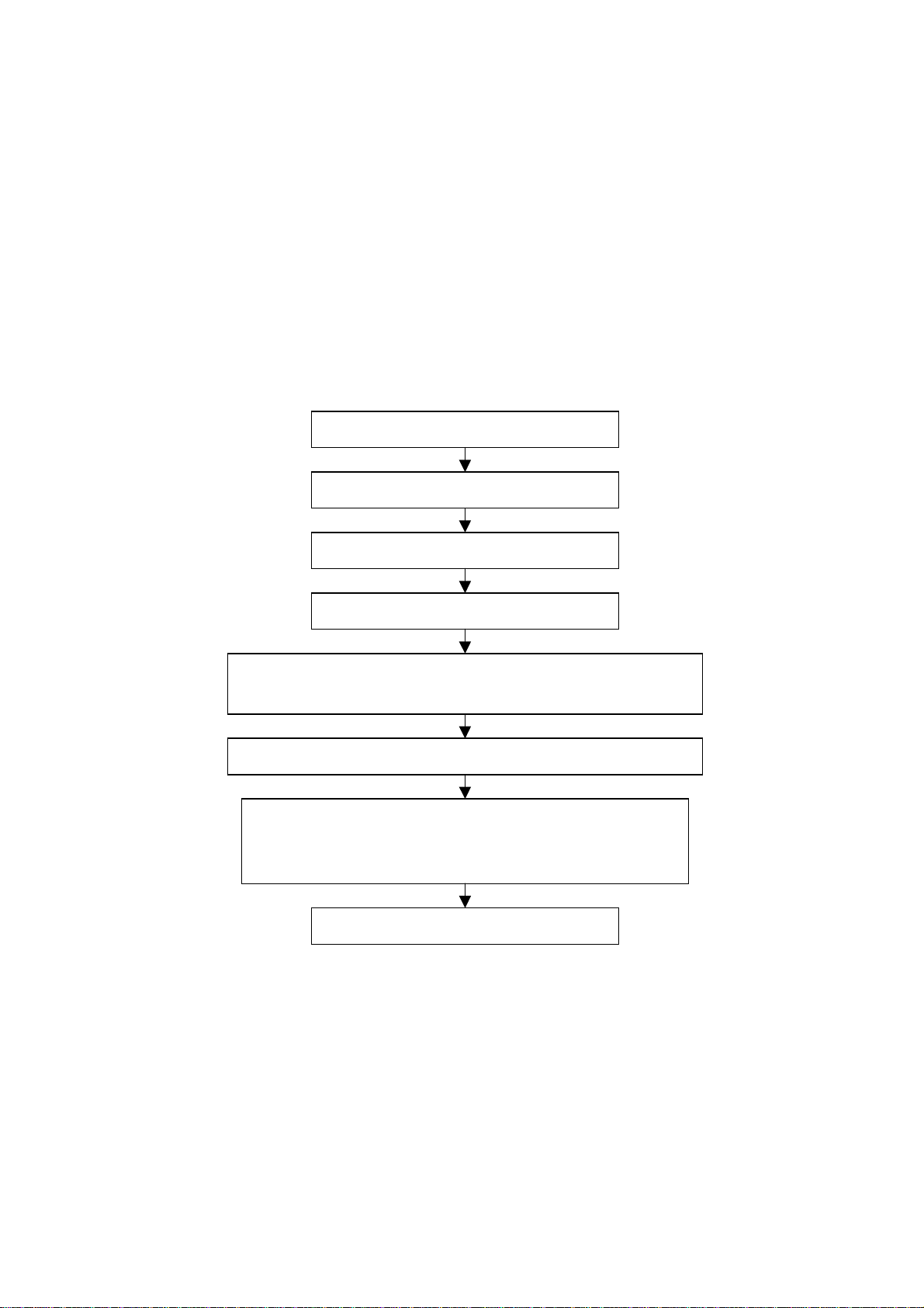
2 Alignment flow-chart
The alignment flow-chart is shown as fig-1
Write memory N300 and N400
To produce main board and power supply board
Check power supply board and main adjustment
Connect with central signal source, then check each function of TV(Statio
missing, system identification, analog co ntrol etc.) , check the o utput of speaker
Input AV/S-video signal, then check each function of AV/S-video
Input YPrPb signal and see if the display is normal under PC status
and check various functions (analog control), line/field center etc.
Check the accessories and pack t hem in box
Fig-1 adjustment flow-chart
3 Unit adjustments
3.1 Flash writing programs
Written memory N300 and N400.
3.2 Check power supply board
Turn off between power supply board and main board, after plug in power, testing X702 (pin1 and
pin5) power supply board voltage to be 12v and 5v.
3.3 main board adjustment
3.3.1 IF amplifier adjustment
a. Turn off the J201, J202, J203, J204, J205 and J5, input 38MHz(PAL SYSTEM) and 45.75MHz(N
All testing
3
Page 6
SYSTEM) for X210, input 9v(±0.05v) and 5v(±0.05v) to J202 and J203, adjust L210 to let x205
voltage to be 1.65v(±0.1v).
b. Solder to J201, J202, J203 and J5
3.3.2 AGC adjustment
Receiving 60dB signal of D-8 or A-7(N system), adjust RP201 to let 3v(±0.05v) of X204.
Input 100dB of antenna, the picture should not no-sync and distortion. Input 35-40db low signals,
the picture should sync and the sound normal, but the color should not disappear.
3.3.3 white balance adjustment
a. Install the unit
b. Adjust to brightness for backlight
c. Access into the D-SUB channel input 16 level gray-scale 640 x 480@60Hz signal of VGA
interface. Press , 2, 5, 8 and 0 buttons access factory menu, perform “reset ex-factory set” and
auto color.
d. Exit factory menu, input gray(H)-8 signal, adjust picture mode to “nature”.
e. Enter factory menu fixed R-OFFSET1 to 0; adjust G-OFFSET1 and B-OFFSET1 to let second
level to fit the table1.
f. Fixed R-GAIN to 200, adjust G-GAIN and B-GAIN to let seventh level to fit table1.
Table1
Color temperature 9300K
X coordinate 0.285±0.008
Y coordinate 0.293±0.008
g. Repeat e step to f step, it must be measure a true value.
h. The unit without VGA interface of 20” (N system), you should be rework c step: enter VIDEO
channel, input Gray(H)-16 for NTSC system of VIDEO interface, press , 2, 5, 8 and 0 buttons to
access factory menu, perform “reset ex-factory set” and auto color.
4. Performance check
a). TV Interfaces
Connect RF port to central signal source. Enter station search menu to auto station search. After
system adjustment is correctly, check if there is any station missing and the output of earphone or
loudspeaker and the picture is normal.
b). Interface of AV/S Terminals
input AV signal and switch to AV channel, see to the picture is normal, then input S terminal, check if
it can auto identify is normal. Check if sound is normal.
c). VGA Interface
Input VGA signal (K7253 signal generator). Separately input the several types of VGA format
signals as listed in Table 1. Then check if the picture and sound is normal. If there has been
interference to the picture then press the auto set key on the remote control once again and check if
the display is normal.
4
Page 7
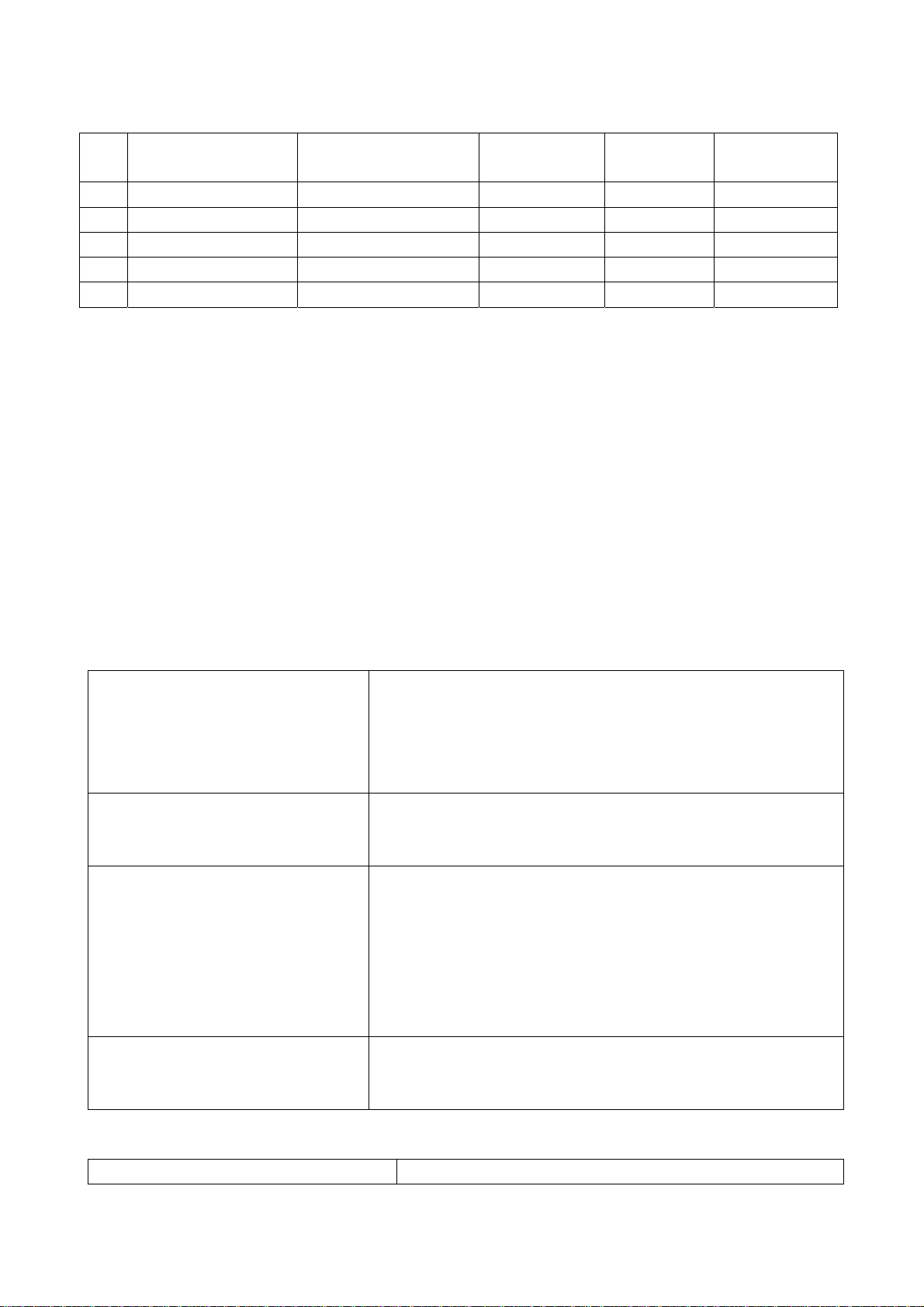
Table 1 Display Format of PC
Item
1 640 x 480 @ 60 25.175 31.469 59.900
2 800 x 600 @ 60 40.000 37.879 60.317
3 1024 x 768 @ 60 65.000 48.363 60.004
4 1024 x 768 @ 70 75 56.48 70.07
5 1280 x 1024 @ 60 109.47 63.72 60
Resolution
Picture element clock
(MHz)
H-SYNC
(kHz)
V-SYNC
(Hz)
Remark
e). YPbPr Interface
Input YPbPr signal to YPbPr/YcbCr interface. Separately input the several types of YPbPr format
signals: 480P/60Hz, 480P/59Hz; 720P/60Hz, 720P/59Hz; 1080i/60Hz, 1080i/59Hz; 1080p/60Hz,
1080p/59Hz and check if the picture and sound is normal.
5. Preset ex-works
In the status of TV enter the factory menu by pressing the factory key and then perform presetting.
6. Ex-works packing
Check accessories and then pack them in box.
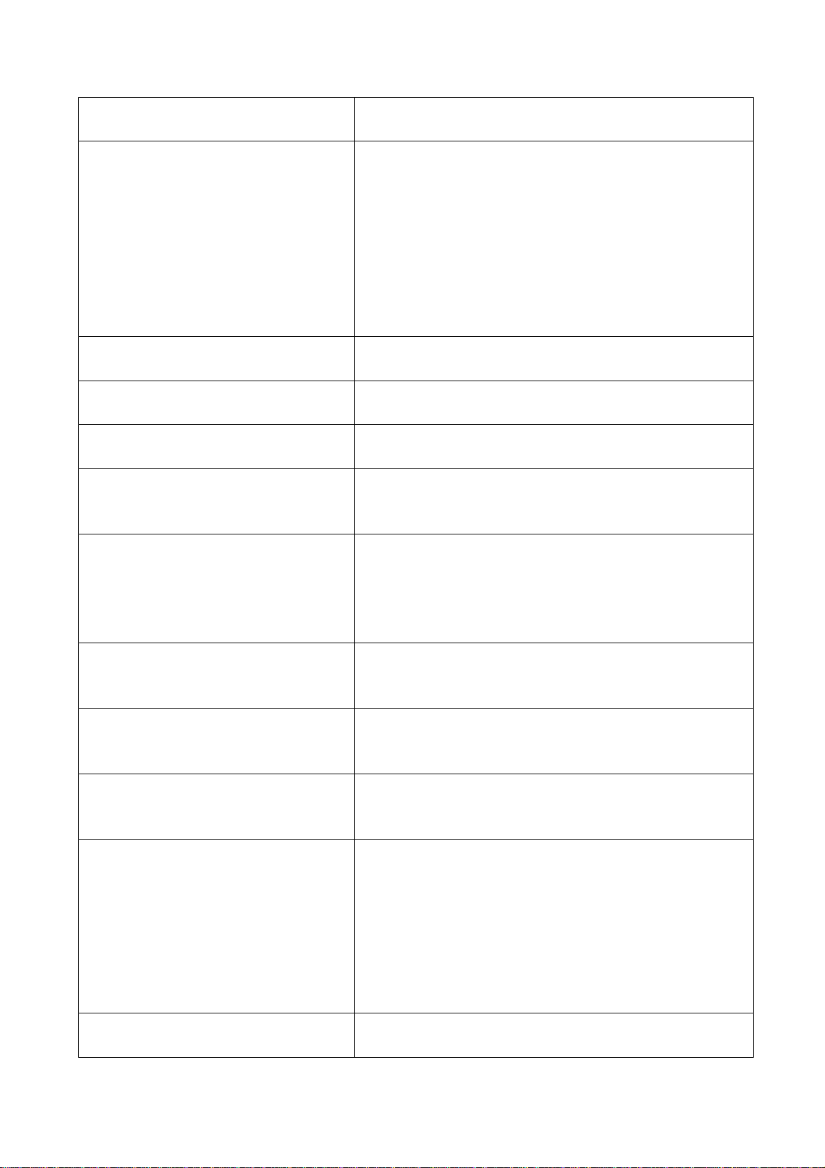
Trouble shooting
Before servicing please check to find the possible causes of the troubles according to the table
below.
1.Antenna (signal):
Picture is out of focus or jumping Bad status in signal receiving
Poor signal
Check if there are failures with the electrical connector or
the antenna.
Check if the antenna is properly connected.
Fringe in picture Check if the antenna is correctly oriented.
Maybe there is electric wave reflected from hilltop or
building.
Picture is interfered by stripe
shaped bright spots
There appear streaks or light color
on the screen
2.TV set:
Symptoms Possible cause
Possibly due to interference from automobile, train, high
voltage transmission line, neon lamp etc.
Maybe there is interference between antenna and power
supply line. Please try to separate them in a longer
distance.
Maybe the shielded-layer of signal wire is not connected
properly to the connector.
Check if interfered by other equipment and if interfered
possibly by the equipment like transmitting antenna,
non-professional radio station and cellular phone.
5
Page 8
Unable to switch the power on Check to see if the power plug has been inserted
properly into the socket.
No picture and sound Check to see if the power supply of liquid crystal TV
has been switched on. ( as can be indicated by the
red LED at the front of the TV set)
See if it’s receiving the signal that is transmitted from
other source than the station
Check if it’s connected to the wrong terminal or if the
input mode is correct.
Check if the signal cable connection between video
source and the liquid crystal TV set is correct.
Deterioration of color phase or color
Check if all the picture setups have been corrected.
tone
Screen position or size is not proper Check is the screen position and size is correctly set
up.
Picture is twisted and deformed Check to see if the picture-frame ratio is properly set
up.
Picture color changed or colorless Check the “Component” or “RGB” settings of the
liquid crystal TV set and make proper adjustment
according to the signal types.
Picture too bright and there is
distortion in the brightest area
Check if the contrast setting is too high.
Possibly the output quality of DVD broadcaster is set
too high.
It maybe also due to improper terminal connection of
the video signal in a certain position of the system.
Picture is whitish or too bright in the
darkest area of the picture
Check if the setting for the brightness is too high
Possibly the brightness grade of DVD player
(broadcaster) is set too high.
No picture or signal produced from the
displayer if “XXX in search” appears.
Check if the cable is disconnected.
Check if it’s connected to the proper terminal or if the
input mode is correct.
There appears an indication - “outside
the receivable scope)
Check if the TV set can receive input signal. The
signal is not correctly identified and VGA format is
beyond the specified scope.
Remote control cannot work properly Check if the batteries are installed in the reverse
order.
Check if the battery is effective.
Check the distance or angle from the monitor.
Check if there is any obstruct between the remote
control and the TV set.
Check if the remote control signal- receiving window
is exposed to strong fluorescence.
No picture and sound, but only hash. Check if the antenna cable is correctly connected, or
if it has received the video signal correctly.
6
Page 9

Blur picture Check if the antenna cable is correctly connected.
Of if it has received the right video signal.
No sound Check if the “mute” audio frequency setting is
selected.
Check if the sound volume is set to minimum.
Make sure the earphone is not connected.
Check if the cable connection is loose.
When playing VHS picture search
tape, there are lines at the top or
bottom of the picture.
When being played or in pause VHS picture search
tape sometimes can’t provide stable picture, which
may lead to incorrect display of the liquid crystal TV,
In this case please press “auto” key on the remote
control so as to enable the liquid crystal TV set to
recheck the signal and then to display correct picture
signal
Method of software upgrading
The Y# series models enable you to update software through the VGA interface.
Hardware requirements: 1. One parallel cable with male end and female end;
2. One standard VGA cable;
3. The updating board specially for Y# mainboard.
The steps for updating software:
1. Install Gprobe 5.0:
The first: Double click the GProbe5[1].0.0.15_S0006-EXE-09A to install it:
According to the prompt of Windows and follow the steps one by one to finish the installation.
The second: Double click the GPorbe5[1].0.0.15Update1_S0006-EXE-10A to install it:
According to the prompt of Windows and follow the steps one by one to finish the installation.
2. Copy the full directory of Isp_fastflash to anywhere
E.g. Take the root directory of C:\ as an example for the following explaination:
Copy the updating file *.hex to the directory of C:\ Isp_fastflash\
E.g. C:\ Isp_fastflash\20Y25.hex.
3. Open C:\ Isp_fastflash\Isp_parallel\ bat.txt as follows:
7
Page 10
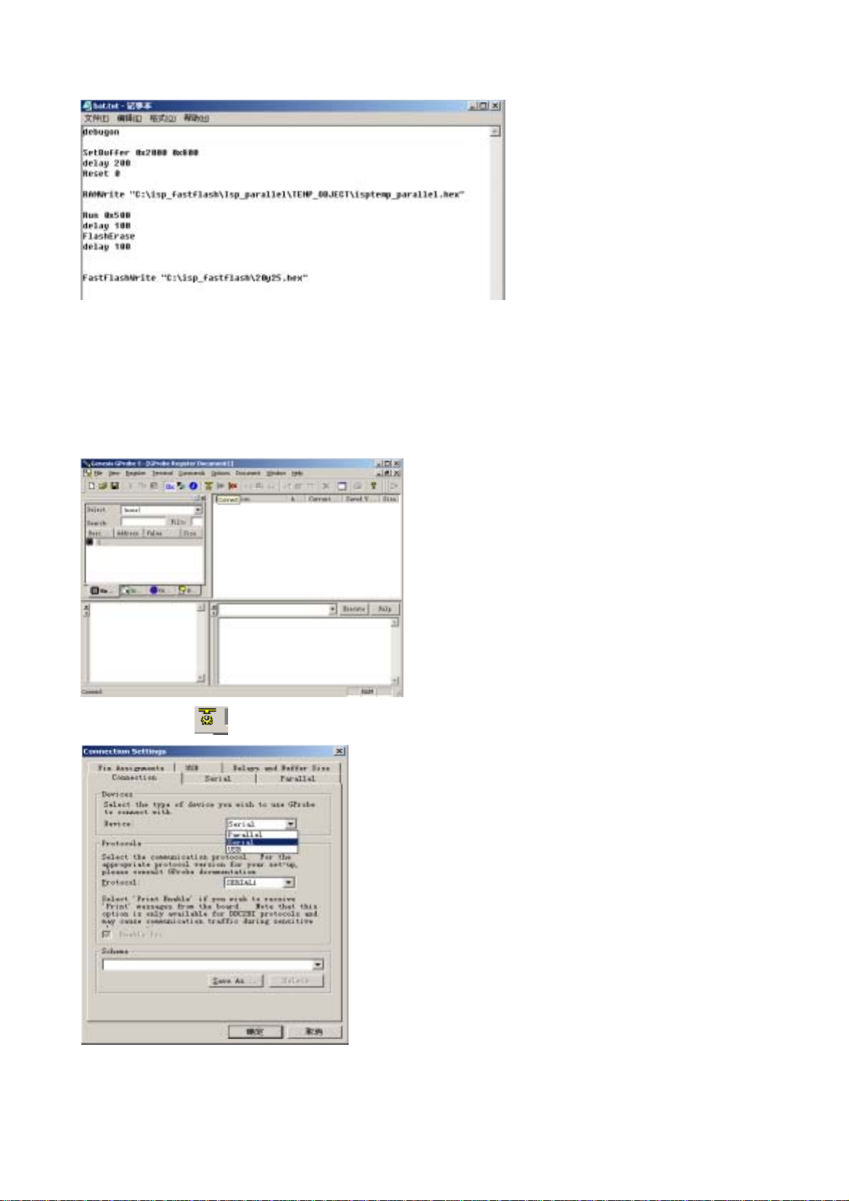
Properly set the path of RAMWrite "C:\isp_fastflash\Isp_parallel\TEMP_OBJECT\isptemp_ parallel.hex"
and FastFlashWrite "C:\isp_fastflash\20y25.hex", save them and close.
4. Set the LCD to off. Connect the Y# updating board and PC with parallel cable.
5. Connect the VGA MONITOR interface on the Y# updating board with the VGA cable, connect the
other end to the VGA interface of the LCD.
6. Turn on the LCD
7. Run Gprobe5
Click the icon of
Set the Device to Parallel.
The click the item of Delays and Buffer Size: Set Long to 50000 ms.
:
8
Page 11
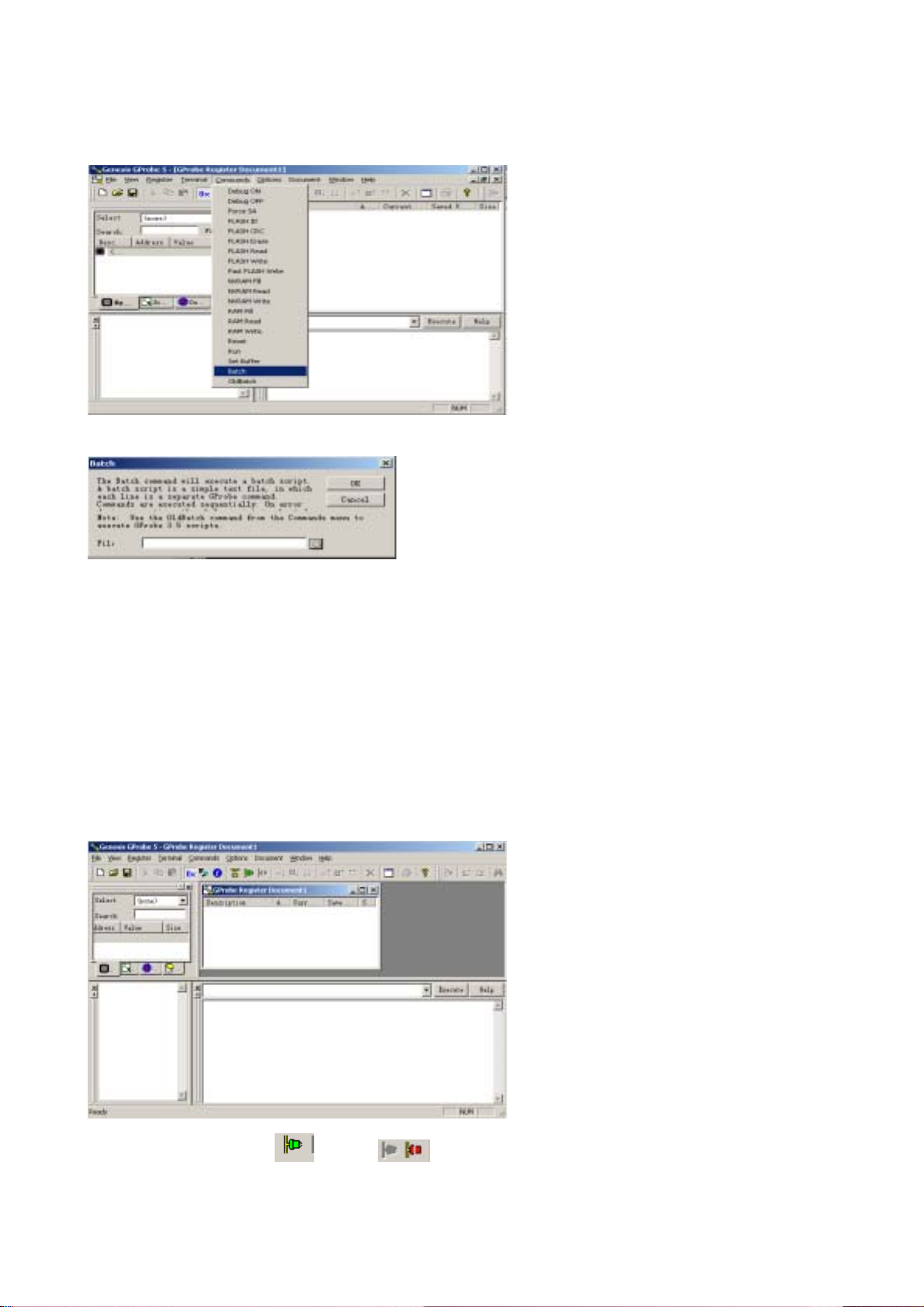
Click the item of Parallel: Set Clock to 120000 Hz.
8. Click Batch,
Select the path of the File: bat.txt
Select bat.txt and click to open it:
Click “OK” to start the process of burning the program. The following screen appears when the process if
finished.
If you want to update the software next time, you just need to click the pull-down menu to select the
desired Batch file and execute it in the following screen.
Note: Do not cut off the power or turn off the unit during the burning process, or the flash may be
damaged.
Check the following if you fail to update:
1. Check whether all cables are properly connected.
2. Check the settings of Gprobe.
3. It is wrong if the Gprobe shows as the following icon.
Now just click the icon of
to show icon.
9
Page 12

LC-Y# series working principle analysis
For the PAL system, when the RF signal is input to the tuner, the turner generates IF signal. Then the IF
signal goes through the pre-amplifying circuit and 38M SAW, the VIF signal and 1ST_SIF signal will be
generated. When these signals are input into the M52760E IC, the VIDEO_OUT and SIF signal will be
generated. Then these two-way signals are sent to HEF4052BT, trapper and filter, which selective output
signal according to different sound systems (PAL D/K, PAL B/G, PAL I). The audio signal returns
toM52760E IC via filter to be decoded and then is sent to R2S15900, while the video signal is transferred
to multi-system signal CVBS_TV via trapper and then is sent to FLI8125 directly.
For the NTSC system, when the RF signal is input to the NTSC tuner, the turner generates IF signal.
Then the IF signals goes through the pre-amplifying circuit and 45.75M SAW, the VIF signal and
1ST_SIF signal will be generated. When these signals are input into the M52760E IC, the VIDEO_OUT
and SIF signal will be generated. Then the SIF signal is sent to MTS decoder LA72700 to perform BTSC
stereo decoding, at last, the signal is input to R2S15900SP. The video signal is transferred to
multi-system signal CVBS_TV via trapper and then is sent to FLI8125 directly.
The AV, YPbPr/YCbCr, S-VHS and VGA signals from the input terminals, with the CVBS_TV signal, are
sent to the main IC FLI8125, after decoding, filtering, De-Interlace, Adc and Scaler, and according to
different panel, the main IC generates a 24-bit TTL signal or LVDS signal to send to the panel to recur
the picture.
10
Page 13
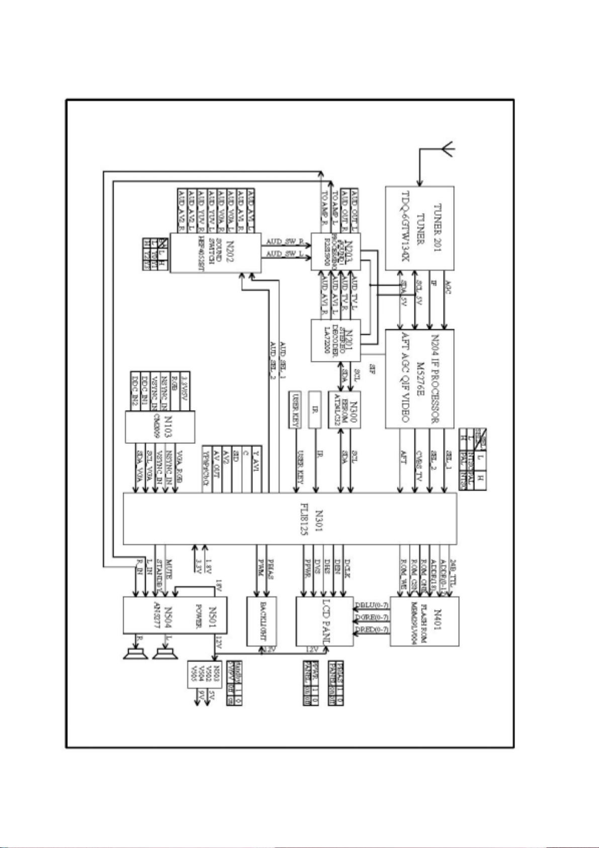
BLOCK DIAGRAM
11
Page 14
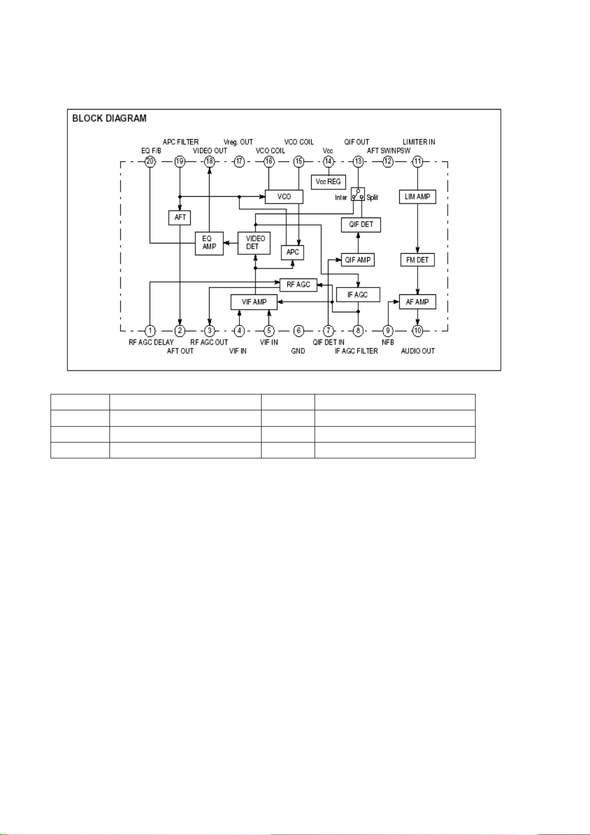
As follows we are going to introduce the inner IC block diagram and function.
1. Inner block diagram of M52760 IF signal processing IC (AFT, QIF, VIDEO OUT)
Descriptions of the pins:
Pin Description Pin Description
4, 5 VIF input 13 QIF OUT
7 1ST_SIF input 14 VCC
10 AUDIO OUT 18 VIDEO OUT
12
Page 15
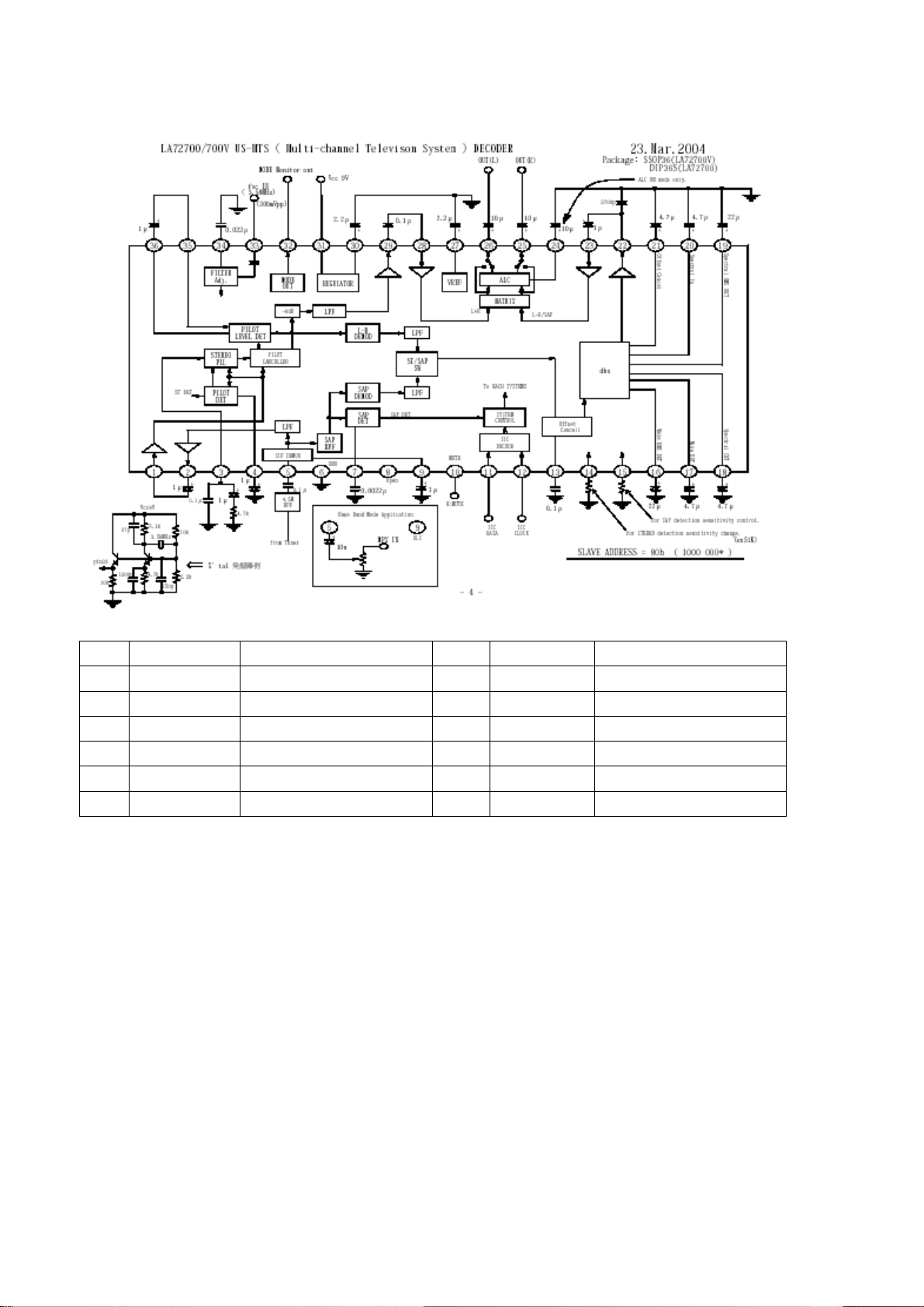
2. Inner block diagram of LA72700 stereo decoder
Descriptions of the pins:
No. Pin name Connections No. Pin name Connections
3 PCSTFILT VCO PLL filter 11 SDA IIC data input
4 PCPLDET Driving level test 12 SCL IIC clock input
5 PISIF SIF signal test 24 PCALCFIL ALC filter
6 GND GND 25/26 R/L OUT TVF_R/L output
9 SIF DEMOD SIF demodulator 27 PCREC Reference voltage
10 MUTE Mute (DC=5V) 31 VCC 9V power
3. R2S15900SP audio processor with surround stereo
The audio signal from YPrPb/YcrCb or VGA input interface is selective sent to R2S15900SP through the
multi-channel selector HEF4052BT, while the audio signal from the AV inputs is sent to R2S15900SP
directly.
After the processing of bass, treble, balance and AVL by R2S15900S, all these processed audio signals
will be output to audio amplifier TPA1517 (for 15 inch models) or AN5277 (for other models) to amplify,
then the amplified signal will be sent to the speaker to output. The Fig.1-3 is the block diagram of
AN5277.
13
Page 16

Descriptions of the pins of R2S15900SP
Pin Function Pin Function
2, 7 Left/right input for Channel 1 17, 18 SDA, SCL
3, 26 Left/right input for Channel 2 28 VCC
4, 25 Left/right input for Channel 3 11, 19 LOUT, ROUT
4. Inner block diagram of AN5277 audio amplifier with single end and double channels
14
Page 17

5. Inner block diagram of TPA1517 6W stereo audio amplifier
6. Inner block diagram of FLI8125 digital video processing IC
15
Page 18

The descriptions of the pins of FLI8125IC
No. Pin name Connections No. Pin name Connections
2 KEYA Key A 43 SID S-video terminal
identification
3 KEYB Key B 47 PWM Pulse width adjustment
7 AFT AFT 51 AUD_SEL_1
10 RESETn Reset 52 AUD_SEL_2
15/ XTAL Resonator
output
16 TCLK Basic clock 64 PPWR Backlight adjustment
24 SCL_RS232 SCL_RS232 90 DEN Display data
25 SDA_RS232 SDA_RS232 91 DVS Display V synchronization
26 SCL_VGA SCL_VGA 92 DHS Display H synchronization
27 SDA_VGA SDA_VGA 93 DCLK Display pixel clock
30 SCL SCL 148 STANDBY Standby
31 SDA SDA 149 MUTE Mute
38 IR_IN Infrared signal
input
63 PBIAS Panel’s oblique line control
161 SEL_1 PAL/NTSC selection_1
16
Page 19

Main assembly
LC-15Y3 LC-20Y15
hanging assy 535-L20H15-00
stand 615-10435-00
(DZ-0615)
615-10483-03
(DZ-2020)
Speaker assy 615-20448-00
Main board 667-L15Y3-01 667-LPY25-01
Power board 667-L15Y3-20 667-L20Y15-20
IR receiving
667-L15Y3-09 667-L20Y15-09
board
Button board 667-L15Y3-05 667-L20Y15-05
Back light
667-L15H3-14C 667-L20H3-14A
board
panel 335-15118-00 (M15X3-L04) 335-2000F-00 (V201V1-T01)
Identification criteria for the bright spot and dark spot of the LCD screen
Category criteria
One single
Bright
t
spo
Dark
spots
Total defected point ≤8 ≤7 ≤5 ≤4 /
Notes:
1. Definition of defected point (bright spot, dark spot): It is identified as a defected point if its area
exceeds 1/2 of a single picture element (R,G,B).
2. Definition of bright spot: It is identified as a bright spot if it is bright in the state of dark field and its
bright size remains unchanged
3. Definition of dark spot: It is identified as a dark spot if it is dark in the state of white field and its
dark size remains unchanged
4. Definition of two neighboring points: Defects of a group of picture elements(RB,RG,GB).
spot
2 neighboring
spots
Total No. ≤5 ≤2 ≤5 ≤2 ≤3
One single
spot
Two
neighboring
spots
Total No. ≤6 ≤7 ≤5 ≤4 ≤10
15" 20" 22" 30" 40" 15" 20" 22" 30" 40"
≤5 ≤2 ≤5 ≤2 ≤3
≤2 ≤1 ≤2 ≤1 ≤1
≤6 ≤7 ≤5 ≤4 ≤10
≤2 ≤2 ≤2 ≤1 ≤5
Q’ty allowed Distance between two spots
≥15mm
≥15mm
≥10mm
≥5mm
17
Page 20

Wiring diagram
indicator light board
Left speaker
Back light board
Button board A
Power board
Main board
Button board B
Right speaker
18
Page 21

Troubleshooting charts
R
r
r
t
r
N
NYN N
This series models adopt built-in power. The power to the main board may be different when the unit
adopts different panels or whether the audio amplifier is located on the main board or not. The following
is the detailed power in different cases.
Model Audio amplifier
LC-20Y25
LC-20Y15
AN5277, locates on
power board, Vcc=18V
LC-15Y3 TPA1517, locates on
mainboard, Vcc=12V
LC-23Y25 AN5277, single audio
amplifier, Vcc=18V
LC-20Y3 AN5277, locates on
mainboard, Vcc=18V
1. No raster, no picture and no sound
When the main power is turned on, the unit’s indicator lights up in red (red indicator is controlled by
+3.3VSTANDBY), use the remote control or the unit’s STANDBY to lights up the blue indicator.
Power socket
number on the
mainboard
Definition of the pins (as follows, PBIAS
refers to backlight ENABLE, PWM refers
to backlight brightness control signal.)
X702
8 pin
X701
6 pin
1, 2: +12V 3, 4: GND 5: +3.4V
6: GND; 7: PBIAS 8: PWM
1, 2: GND 3, 4: +12V
5: PBIAS 6: PWM
X702 1, 2, 3: +20V; 4, 5, 6: GND
7: STANDBY 8: +3.3V
X702 1,2: +12V 3, 4: GND 5,6: +18V
7,8: GND 9: PBIAS 10: PWM
Whether the I
board’s red indicato
lights up?
Y
Whether the blue
indicator lights up
when press the
STANDBY button?
Y
Whether the
backlight lights up?
Whether the backlight
Whether the
power or PBIAS pin is
backlight power o
PBIAS pin is normal
Power board’s +3.3V
is abnormal
Confirm the IR
sensor and its powe
supply is normal
YY
Whether the voltage
of the panel is
normal?
Y
Backlight board damage or protection.
Replace the backlight board
Indicator damages or blue
indicator +9V power is
abnormal (check +9V circuit)
8125 is abnormal without
signal output or the outpu
signal is abnormal
Check power circuit or whether the 8125
PBIAS signal is normal
19
Page 22

2. With picture and without sound when turning on:
t
r
N
N
Increase the volume;
check whether every
channel has no sound
Check if the no sound channel from the
signal input to sound processing IC
IC15900 is normal
Y
Check whether the signal
output by 15900(IC) is
normal
15900(IC) or peripheral circui
does not work normally
Y
Sound amplifier o
peripheral circuit does
not work normally
3. When receiving TV signal, there is no picture or dark snow:
Confirm the +5V, +32V power supply of TUNER, confirm +5V, +9V power supply of IF amplifier is normal.
If they are normal, check whether peripheral circuit of the TUNER or IF amplifier is normal. If they are all
no problem, then 8125 or its input signal is abnormal.
4. In TV channel, the picture or sound is abnormal; the frequency of the menu is different from the actual
frequency.
Connect the signal cable; manually adjust the frequency to conform to the actual frequency. Enter into
service menu; check AFT value should be about 1.6V. If the difference is serious (the difference is larger
than 0.4V), open the cabinet and adjust the transformer until the value of AFT is 1.6V.
20
Page 23

5. Check flow of the power board:
k
N
N
N
N N
Power board damages
or fuse blows
Check whether C512 has 18V Replace D502
Check whether pin1 of N501 has
wave
Check whether N502 is damaged
Check whether N505, D507 is
damaged
Y Y
Replace the fuse and chec
whether N901, D501
breakdown
Y
Y
Y
Replace N502
Check whether N505 is
damaged
Y
Replace N501, D501
Y
Replace
N505
Replace the damaged
parts
21
Page 24

Exploded views
LC-15Y3
22
Page 25

PART LIST OF EXPLODED VIEW
NO. DESCRIPTION PART#
1 Nameplate 881-63190-39
2 Transfer axis cover 808-10609-120
3 Screw 851-14010-56
4 Back cover 780-11019P124
5 Button baffle 743-10132-01
6 Button 667-L15Y3-05
7 Screw 852-33005-81
8 Screw 851-33008-51
9 Speaker 384-30308-D0
10 IR receiver board 667-L15Y3-09
11 LED column 700-60188-100
12 LOGO no number(silk screen)
13 Front cover 780-11018J0G5
14 LCD panel 335-15120-00
15 LCD fixed support 803-1I128-00B
16 Main board 667-L15Y3-01
17 Main board shield cover 859-11258-00A
18 Stand 615-10435-05
23
Page 26

PART LIST
PART# DESCRIPTION LOCA.NO.
203-L15Y30-25 LC-15YS031 BRAND PRIMA,N-M,CUL,
100-L15Y30-01 LC-15Y3 07
SL15Y30-23A10 SOFTWARE SVA PANEL N401
SL20Y190-02B10 SOFTWARE DDC N104
364-41215-00 ANTENNA SOCKET NF-6
384-30308-D0 SPEAKER YDT4070 3W 8Ω
459-2410R-002 CERAMIC CAPACITOR DD308-63F104Z50
491-5521J-02 POWER CORD UL !
655-4E301-118 (4-PINS) LEAD WITH HOUSING
655-44301-32 (4-PINS) LEAD WITH HOUSING
655-44302-31 (4-PINS) LEAD WITH HOUSING
655-61201-12 (6-PINS) LEAD WITH HOUSING
655-61202-148 (6-PINS) LEAD WITH HOUSING
665-D0002-650 LVDS LINE 30-PINS120mm X409
665-N0300-00 COAXIAL CABLE CSYV-2B-300
666-12301-00 FERRITE BEAD TY23X13.5X6
700-60188-100 LED PIECE ( MOLD TRANSPARENT GREY 0A )
742-30005-09 LINE TIE
742-30005-09 LINE TIE
743-10132-01 DECORATIVE PIECE (SILK-SCREEN )
780-11018-0GA FRONT CABINET ( SILVERY WHITE 06,SILK-SCREEN )
780-11019-AF3 BACK CABINET ( GREY 05,SILK-SCREEN )
804-2F318-00A INTERFACE SPACE PLATE
808-60713-00 HANDLE CUSHION
808-70350-00 INSULATOR
808-70365-00 INSULATOR
822-10181-00 GLUE COVER
851-13008-11 SCREW P(+) T3X8A-DZn
851-14010-56 SCREW P(+) T4X10S-R
851-33008-51 SCREW B(+)3X8G-D.Zn
851-33008-51 SCREW B(+)3X8G-D.Zn
851-43010-11 SCREW F(+)T3x10A-DZn
851-43010-56 SCREW F(+)T3X10G-R
852-33005-81 SCREW B(+) M3X5-D.Zn
852-33005-81 SCREW B(+) M3X5-D.Zn
852-33005-81 SCREW B(+) M3X5-D.Zn
852-33005-87 SCREW B(+) M3X5-D.Zn ( BLACK )
852-33008-81 SCREW B(+) M3X8-D.Zn
852-43006-85 SCREW F(+)M3X6- BLACK
852-43006-85 SCREW F(+)M3X6- BLACK
859-11258-00A MAIN BOARD SHIELD COVER
863-80910-00 POLY FOAM (TOP )
863-80911-00 POLY FOAM (BOTTOM )
870-30068-AF0 HOLDER ( GREY 05)
877-30267-00 HANDLE
877-50447-00 TOUCH KEY
877-50448-0T0 KEY CAP ( PLATE SILVERY WHITE )
Page 27

881-60085 BLANK WARNING LABEL
)
887-20171-00 PALSTIC BAG 70-500-0.06
887-21074-00 PALSTIC BAG (100X230)
887-21135-02 CLASPER PALSTIC BAG 230X330X0.1
335-15120-00 DISPLAY SCREEN SVA 150XG04TB !
488-10012-00 BATTERY 7# ENGLISH
604-L15Y37-04 OWNER'S MANUAL(PRIMA CAN/SVA PANEL )
665-D0002-421 VIDEO LINE BLUE GREEN RED
665-D0002-422 VIDEO LINE YELLOW WHITE RED
803-1I128-00B LCD SCREEN FRAME
803-30202-00 CONNECT PIECE ( LEFT )
803-30203-00 CONNECT PIECE ( RIGHT )
881-L15Y37-00 OPERATION CARD (8.5X11)
881-63016-00A POWER SYMBOL LABEL ( T2751)
881-63190-39 BACK PLATE LABEL (LC-15Y3S031,PRIMA
881-64101-00 MYLAR LABE LABEL LEC1523,LEGEND
881-80658-00 SERVICE CARD ENGLISH FRENCH, LCD14-26
886-31421-15 CARTON BOX (LC-15Y3,PRIMA)
887-20047-04A ACCESSORY PALSTIC BAG ( ENGLISH FRENCH SPANISH
887-21189-P1 PE/PEARL COTTONPALSTIC BAG 560X470
301-Q20Y15-28MB RC-Q28M-0BREMOTE CONTROL UNIT (PRIMA NEW)
353-34282-30 SMD ICM34282M1-D48GP (M)
615-10354-05 HOLDER ASS'Y (DZ-0715)
605-L15Y37-01 HOLDER INSTALLATION GUIDE(DIGISTAR)
615-20087-00 AXLETREE ASS'Y
804-20328-00 CONNECT PIECE
807-20192-0G0 HOLDER ( SILVER WHITE 06)
808-10605-AF0 STAND COLUMN FRONT COVER ( GREY 05)
808-10606-0G0 STAND COLUMN BACK COVER ( SILVER WHITE 06 )
808-10609-AF0 AXLETREE COVER BOARD ( GREY 05)
851-33008-51 SCREW B(+)3X8G-D.Zn
851-33012-57 SCREW B(+)3X12G-D.Zn ( BLACK )
851-43008-56 SCREW F(+)T3X8G-R
852-34008-87 SCREW B(+) M4X8-D.Zn ( BLACK )
852-34008-87 SCREW B(+) M4X8-D.Zn ( BLACK )
868-20686-00 CUSHION
880-10527-0G0 BACK PLATE ( SILVER WHITE 06)
887-21195-00 PALSTIC BAG (350X220X0.05)
667-L15Y3-01 MAIN PCB ASS'Y
667-L15Y3-01\ MAIN PCB ASS'Y ( MANUAL INSERTION )
329-53601-00 CRYSTAL JA25A 3.579545MHZ G301
329-61901-00 CRYSTAL HC-49u 19.6608MHz G401
340-50950-003 ZENER DIODE HZ9C3 D701
343-01800-00 TRANSISTOR KSE180 TO-126 V706
352-05550-00 *IC LM555CN (M) N203
352-05740-00 IC uPC574 (D) N202
352-15170-10 IC TPA1517NE (D) N303
Page 28

352-52760-10 IC M52760SP N201
364-11212-00 EARPHONE JACK ST-112 X101
364-11212-00 EARPHONE JACK ST-112 X103
364-34101-00 4-PINS CONNECTORS TJC3-04A X302
364-34101-00 4-PINS CONNECTORS TJC3-04A X401
364-34186-00 4-PINS CONNECTORS TJC10-4AWT X402
364-36101-00 6-PINS CONNECTORS TJC3-06A X701
364-91202-00 S-VIDEO TERMINAL CKX5-2K-2 X10⁵
364-91204-00 VGA SOCKET 105 PIN 3 ROW HORIZONTAL ( 阴) X106
364-93219-00 AV JACK AV3-14WKD X104
364-93220-00 AV JACK AV3-14WD X102
458-07009-00 SAW FILTER M1859M Z202
458-07016-00 SAW FILTER M9370M30 Z201
462-B0422-H0 POLYESTER CAPACITOR CL21X-50V-0.22uF-J C219
464-6C622-M02 ELECTROLYTIC CAPACITOR CD110-10V-22uF-M C458
464-6D810-M1 ELECTROLYTIC CAPACITOR CD110-16V-1000uF-M C355
464-6D810-M1 ELECTROLYTIC CAPACITOR CD110-16V-1000uF-M C358
464-6D810-M1 ELECTROLYTIC CAPACITOR CD110-16V-1000uF-M C363
464-6D810-M1 ELECTROLYTIC CAPACITOR CD110-16V-1000uF-M C364
464-6D810-M1 ELECTROLYTIC CAPACITOR CD110-16V-1000uF-M C719
468-33207-00 POTENTIOMETER EVND8A-20K RP201
471-1110H-00 PEAKING COIL EL0606SKI-101J L202
471-1110H-00 PEAKING COIL EL0606SKI-101J L208
471-1110H-00 PEAKING COIL EL0606SKI-101J L213
471-1210K-00 PEAKING COIL EL0606SKI-102K L206
471-2B56K-013 PEAKING COIL SPT0305-R56K-5 L201
471-2B56K-013 PEAKING COIL SPT0305-R56K-5 L204
471-2012K-A0 PEAKING COIL SP0203-12uH-K L212
475-15451-00 CERAMIC FILTER LT4.5MH Z205
475-25451-00 CERAMIC TRAP FILTER XT4.5MB Z210
477-60095-00 COIL 7KL004A L207
590-40721-00 TUNER TDQ-6F/W134X TUNER201
706-V1601-01 HEAT SINK SRP301
742-30005-09 LINE TIE
998 JUMPER WIRE D203
667-L15Y3-01* MAIN PCB ASS'Y (AUTOMATIC INSERTION ,SMD )
340-00001-0S SMD DIODE LL4148 D206
340-00001-0S SMD DIODE LL4148 D303
340-00001-0S SMD DIODE LL4148 D101
340-00001-0S SMD DIODE LL4148 D102
340-00001-0S SMD DIODE LL4148 L103
340-00001-0S SMD DIODE LL4148 L104
340-00296-00 SMD DIODE SK34 D702
340-00296-00 SMD DIODE SK34 D703
342-01380-00 *SMD TRANSISTOR BSS138LT1 V301
342-01380-00 *SMD TRANSISTOR BSS138LT1 V302
342-08470-90 SMD TRANSISTOR BC847AW V104
342-08470-90 SMD TRANSISTOR BC847AW V105
342-08470-90 SMD TRANSISTOR BC847AW V106
342-08470-90 SMD TRANSISTOR BC847AW V303
Page 29

342-08470-90 SMD TRANSISTOR BC847AW V304
342-08470-90 SMD TRANSISTOR BC847AW V305
342-08470-90 SMD TRANSISTOR BC847AW V312
342-08470-90 SMD TRANSISTOR BC847AW V701
342-08470-90 SMD TRANSISTOR BC847AW V702
342-08470-90 SMD TRANSISTOR BC847AW V703
342-08470-90 SMD TRANSISTOR BC847AW V705
342-08470-90 SMD TRANSISTOR BC847AW V401
342-08470-90 SMD TRANSISTOR BC847AW V216
342-08470-90 SMD TRANSISTOR BC847AW V217
342-08470-90 SMD TRANSISTOR BC847AW V404
342-08570-90 SMD TRANSISTOR BC857 AW V208
342-08570-90 SMD TRANSISTOR BC857 AW V309
342-08570-90 SMD TRANSISTOR BC857 AW V704
343-21200-104 TRANSISTOR 2SC2120-Y V207
343-27170-004 TRANSISTOR 2SC2717 V201
353-03580-80 SMD IC LM358D (M) N704
353-05040-20 SMD IC PESD5V0L4UG N102
353-05050-20 SMD IC PESD5V0L5UY N101
353-05050-20 SMD IC PESD5V0L5UY N103
353-05050-20 SMD IC PESD5V0L5UY N105
353-11170-G0 SMD IC AMS1117-1.8 (D) N403
353-14100-10 SMD IC MPS1410ES (M) N703
353-14100-10 SMD IC MPS1410ES (M) N701
353-15900-10 SMD ICR2S15900SP N302
353-24210-10 SMD IC 24LCS21A/SN N104
353-24320-50 SMD IC24LC32A/SN N401
353-29040-10 SMD IC MX29LV040QC-70 N404
353-72700-10 SMD IC LA72700V-N N301
353-81250-10 SMD IC FLI8125-BC N402
353-99330-00 SMD IC SI9933ADY (O) N702
364-T3001-00 SMD 30-PINSFF-A1255-WRS X409
455-12A22-H0 SMD RESISTOR FTR06032R2JR R344
455-12A22-H0 SMD RESISTOR FTR06032R2JR R345
455-12000-H0 SMD RESISTOR FTR0603000XR R214
455-12000-H0 SMD RESISTOR FTR0603000XR R216
455-12000-H0 SMD RESISTOR FTR0603000XR R241
455-12000-H0 SMD RESISTOR FTR0603000XR R254
455-12000-H0 SMD RESISTOR FTR0603000XR R150
455-12000-H0 SMD RESISTOR FTR0603000XR R151
455-12000-H0 SMD RESISTOR FTR0603000XR R152
455-12000-H0 SMD RESISTOR FTR0603000XR C23
455-12000-H0 SMD RESISTOR FTR0603000XR C24
455-12011-H0 SMD RESISTOR FTR0603110JR R301
455-12011-H0 SMD RESISTOR FTR0603110JR R302
455-12020-H0 SMD RESISTOR FTR0603200JR R401
455-12020-H0 SMD RESISTOR FTR0603200JR R402
455-12020-H0 SMD RESISTOR FTR0603200JR R403
455-12020-H0 SMD RESISTOR FTR0603200JR R404
455-12020-H0 SMD RESISTOR FTR0603200JR R405
Page 30

455-12020-H0 SMD RESISTOR FTR0603200JR R406
455-12020-H0 SMD RESISTOR FTR0603200JR R407
455-12020-H0 SMD RESISTOR FTR0603200JR R408
455-12020-H0 SMD RESISTOR FTR0603200JR R409
455-12020-H0 SMD RESISTOR FTR0603200JR R410
455-12020-H0 SMD RESISTOR FTR0603200JR R411
455-12020-H0 SMD RESISTOR FTR0603200JR R412
455-12020-H0 SMD RESISTOR FTR0603200JR R413
455-12022-H0 SMD RESISTOR FTR0603220JR R201
455-12022-H0 SMD RESISTOR FTR0603220JR R202
455-12022-H0 SMD RESISTOR FTR0603220JR R415
455-12022-H0 SMD RESISTOR FTR0603220JR R416
455-12022-H0 SMD RESISTOR FTR0603220JR R417
455-12022-H0 SMD RESISTOR FTR0603220JR R422
455-12022-H0 SMD RESISTOR FTR0603220JR R423
455-12022-H0 SMD RESISTOR FTR0603220JR R426
455-12022-H0 SMD RESISTOR FTR0603220JR R427
455-12022-H0 SMD RESISTOR FTR0603220JR R428
455-12022-H0 SMD RESISTOR FTR0603220JR R429
455-12022-H0 SMD RESISTOR FTR0603220JR R430
455-12022-H0 SMD RESISTOR FTR0603220JR R431
455-12022-H0 SMD RESISTOR FTR0603220JR R432
455-12022-H0 SMD RESISTOR FTR0603220JR R433
455-12022-H0 SMD RESISTOR FTR0603220JR R434
455-12022-H0 SMD RESISTOR FTR0603220JR R435
455-12027-H0 SMD RESISTOR FTR0603270JR R209
455-12051-H0 SMD RESISTOR FTR0603510JR R203
455-12056-H0 SMD RESISTOR FTR0603560JR R232
455-12075-H0 SMD RESISTOR FTR0603750JR R104
455-12075-H0 SMD RESISTOR FTR0603750JR R105
455-12075-H0 SMD RESISTOR FTR0603750JR R117
455-12075-H0 SMD RESISTOR FTR0603750JR R118
455-12075-H0 SMD RESISTOR FTR0603750JR R119
455-12075-H0 SMD RESISTOR FTR0603750JR R128
455-12075-H0 SMD RESISTOR FTR0603750JR R129
455-12075-H0 SMD RESISTOR FTR0603750JR R130
455-12075-H0 SMD RESISTOR FTR0603750JR R136
455-12075-H0 SMD RESISTOR FTR0603750JR R138
455-12075-H0 SMD RESISTOR FTR0603750JR R140
455-12110-H0 SMD RESISTOR FTR0603101JR R204
455-12110-H0 SMD RESISTOR FTR0603101JR R308
455-12110-H0 SMD RESISTOR FTR0603101JR R311
455-12110-H0 SMD RESISTOR FTR0603101JR R25
455-12110-H0 SMD RESISTOR FTR0603101JR R448
455-12110-H0 SMD RESISTOR FTR0603101JR R731
455-12110-H0 SMD RESISTOR FTR0603101JR R732
455-12110-H0 SMD RESISTOR FTR0603101JR R158
455-12110-H0 SMD RESISTOR FTR0603101JR R159
455-12110-H0 SMD RESISTOR FTR0603101JR R462
455-12110-H0 SMD RESISTOR FTR0603101JR R463
Page 31

455-12110-H0 SMD RESISTOR FTR0603101JR R460
455-12110-H0 SMD RESISTOR FTR0603101JR R461
455-12115-H0 SMD RESISTOR FTR0603151JR R210
455-12115-H0 SMD RESISTOR FTR0603151JR R31
455-12122-H0 SMD RESISTOR FTR0603221JR R249
455-12133-H0 SMD RESISTOR FTR0603331JR R141
455-12133-H0 SMD RESISTOR FTR0603331JR R142
455-12133-H0 SMD RESISTOR FTR0603331JR R143
455-12133-H0 SMD RESISTOR FTR0603331JR R256
455-12133-H0 SMD RESISTOR FTR0603331JR R27
455-12133-H0 SMD RESISTOR FTR0603331JR R28
455-12147-H0 SMD RESISTOR FTR0603471JR R242
455-12191-H0 SMD RESISTOR FTR0603911JR R206
455-12210-H0 SMD RESISTOR FTR0603102JR R230
455-12210-H0 SMD RESISTOR FTR0603102JR R303
455-12210-H0 SMD RESISTOR FTR0603102JR R325
455-12210-H0 SMD RESISTOR FTR0603102JR R328
455-12210-H0 SMD RESISTOR FTR0603102JR R341
455-12210-H0 SMD RESISTOR FTR0603102JR R701
455-12210-H0 SMD RESISTOR FTR0603102JR R707
455-12210-H0 SMD RESISTOR FTR0603102JR R713
455-12210-H0 SMD RESISTOR FTR0603102JR R720
455-12210-H0 SMD RESISTOR FTR0603102JR R346
455-12210-H0 SMD RESISTOR FTR0603102JR R48
455-12210-H0 SMD RESISTOR FTR0603102JR R725
455-12210-H0 SMD RESISTOR FTR0603102JR R30
455-12218-H0 SMD RESISTOR FTR0603182JR R420
455-12218-H0 SMD RESISTOR FTR0603182JR R421
455-12222-H0 SMD RESISTOR FTR0603222JR R319
455-12222-H0 SMD RESISTOR FTR0603222JR R702
455-12222-H0 SMD RESISTOR FTR0603222JR R704
455-12222-H0 SMD RESISTOR FTR0603222JR R49
455-12222-H0 SMD RESISTOR FTR0603222JR R449
455-12222-H0 SMD RESISTOR FTR0603222JR R418
455-12222-H0 SMD RESISTOR FTR0603222JR R419
455-12224-H0 SMD RESISTOR FTR0603242JR R228
455-12227-H0 SMD RESISTOR FTR0603272JR R213
455-12227-H0 SMD RESISTOR FTR0603272JR R215
455-12227-H0 SMD RESISTOR FTR0603272JR R255
455-12230-H0 SMD RESISTOR FTR0603302JR R257
455-12233-H0 SMD RESISTOR FTR0603332JR R258
455-12233-H0 SMD RESISTOR FTR0603332JR R703
455-12233-H0 SMD RESISTOR FTR0603332JR R709
455-12239-H0 SMD RESISTOR FTR0603392JR R205
455-12247-H0 SMD RESISTOR FTR0603472JR R124
455-12247-H0 SMD RESISTOR FTR0603472JR R127
455-12247-H0 SMD RESISTOR FTR0603472JR R131
455-12247-H0 SMD RESISTOR FTR0603472JR R320
455-12247-H0 SMD RESISTOR FTR0603472JR R322
455-12247-H0 SMD RESISTOR FTR0603472JR R437
Page 32

455-12247-H0 SMD RESISTOR FTR0603472JR R424
455-12247-H0 SMD RESISTOR FTR0603472JR R425
455-12251-H0 SMD RESISTOR FTR0603512JR R306
455-12251-H0 SMD RESISTOR FTR0603512JR R313
455-12251-H0 SMD RESISTOR FTR0603512JR R317
455-12268-H0 SMD RESISTOR FTR0603682JR R135
455-12268-H0 SMD RESISTOR FTR0603682JR R137
455-12268-H0 SMD RESISTOR FTR0603682JR R139
455-12268-H0 SMD RESISTOR FTR0603682JR R314
455-12268-H0 SMD RESISTOR FTR0603682JR R315
455-12275-H0 SMD RESISTOR FTR0603752JR R224
455-12282-H0 SMD RESISTOR FTR0603822JR R309
455-12282-H0 SMD RESISTOR FTR0603822JR R323
455-12282-H0 SMD RESISTOR FTR0603822JR R348
455-12310-H0 SMD RESISTOR FTR0603103JR R132
455-12310-H0 SMD RESISTOR FTR0603103JR R133
455-12310-H0 SMD RESISTOR FTR0603103JR R134
455-12310-H0 SMD RESISTOR FTR0603103JR R212
455-12310-H0 SMD RESISTOR FTR0603103JR R217
455-12310-H0 SMD RESISTOR FTR0603103JR R231
455-12310-H0 SMD RESISTOR FTR0603103JR R245
455-12310-H0 SMD RESISTOR FTR0603103JR R316
455-12310-H0 SMD RESISTOR FTR0603103JR R318
455-12310-H0 SMD RESISTOR FTR0603103JR R321
455-12310-H0 SMD RESISTOR FTR0603103JR R331
455-12310-H0 SMD RESISTOR FTR0603103JR R333
455-12310-H0 SMD RESISTOR FTR0603103JR R335
455-12310-H0 SMD RESISTOR FTR0603103JR R340
455-12310-H0 SMD RESISTOR FTR0603103JR R444
455-12310-H0 SMD RESISTOR FTR0603103JR R445
455-12310-H0 SMD RESISTOR FTR0603103JR R705
455-12310-H0 SMD RESISTOR FTR0603103JR R706
455-12310-H0 SMD RESISTOR FTR0603103JR R710
455-12310-H0 SMD RESISTOR FTR0603103JR R715
455-12310-H0 SMD RESISTOR FTR0603103JR R718
455-12310-H0 SMD RESISTOR FTR0603103JR R721
455-12310-H0 SMD RESISTOR FTR0603103JR R723
455-12310-H0 SMD RESISTOR FTR0603103JR R724
455-12310-H0 SMD RESISTOR FTR0603103JR R727
455-12310-H0 SMD RESISTOR FTR0603103JR R347
455-12310-H0 SMD RESISTOR FTR0603103JR R708
455-12310-H0 SMD RESISTOR FTR0603103JR R728
455-12310-H0 SMD RESISTOR FTR0603103JR R730
455-12316-H0 SMD RESISTOR FTR0603163JR R726
455-12320-H0 SMD RESISTOR FTR0603203JR R234
455-12320-H0 SMD RESISTOR FTR0603203JR R729
455-12330-H0 SMD RESISTOR FTR0603303JR R717
455-12330-H0 SMD RESISTOR FTR0603303JR R304
455-12333-H0 SMD RESISTOR FTR0603333JR R29
455-12339-H0 SMD RESISTOR FTR0603393JR R221
Page 33

455-12343-H0 SMD RESISTOR FTR0603433JR R237
455-12347-H0 SMD RESISTOR FTR0603473JR R106
455-12347-H0 SMD RESISTOR FTR0603473JR R107
455-12347-H0 SMD RESISTOR FTR0603473JR R120
455-12347-H0 SMD RESISTOR FTR0603473JR R121
455-12347-H0 SMD RESISTOR FTR0603473JR R122
455-12347-H0 SMD RESISTOR FTR0603473JR R123
455-12347-H0 SMD RESISTOR FTR0603473JR R310
455-12347-H0 SMD RESISTOR FTR0603473JR R324
455-12347-H0 SMD RESISTOR FTR0603473JR R438
455-12347-H0 SMD RESISTOR FTR0603473JR R439
455-12347-H0 SMD RESISTOR FTR0603473JR R440
455-12347-H0 SMD RESISTOR FTR0603473JR R441
455-12347-H0 SMD RESISTOR FTR0603473JR R442
455-12347-H0 SMD RESISTOR FTR0603473JR R443
455-12347-H0 SMD RESISTOR FTR0603473JR R446
455-12347-H0 SMD RESISTOR FTR0603473JR R447
455-12347-H0 SMD RESISTOR FTR0603473JR R722
455-12351-H0 SMD RESISTOR FTR0603513JR R240
455-12356-H0 SMD RESISTOR FTR0603563JR R26
455-12410-H0 SMD RESISTOR FTR0603104JR R243
455-12410-H0 SMD RESISTOR FTR0603104JR R716
455-12415-H0 SMD RESISTOR FTR0603154JR R238
455-12439-H0 SMD RESISTOR FTR0603394JR R235
455-22000-H0 SMD RESISTOR RC11-1/8W-0-J R349
455-22000-H0 SMD RESISTOR RC11-1/8W-0-J J703
455-22110-H0 SMD RESISTOR RC11-1/8W-100-J R229
455-22110-H0 SMD RESISTOR RC11-1/8W-100-J R233
455-22110-H0 SMD RESISTOR RC11-1/8W-100-J R330
455-22130-H0 SMD RESISTOR RC11-1/8W-300-J R712
455-22156-H0 SMD RESISTOR RC11-1/8W-560-J R239
455-22210-H0 SMD RESISTOR RC11-1/8W-1K-J R236
455-30022-H9 SMD RESISTOR NCA4R220JR R436
456-2118H-11 SMD CAPACITOR 0603CG181J250BA C336
456-2210K-B1 SMD CAPACITOR 06032R102K250BA C337
456-2310R-C1 SMD CAPACITOR 06032E103Z250BA C206
456-2310R-C1 SMD CAPACITOR 06032E103Z250BA C207
456-2310R-C1 SMD CAPACITOR 06032E103Z250BA C211
456-2310R-C1 SMD CAPACITOR 06032E103Z250BA C212
456-2310R-C1 SMD CAPACITOR 06032E103Z250BA C215
456-2310R-C1 SMD CAPACITOR 06032E103Z250BA C216
456-2310R-C1 SMD CAPACITOR 06032E103Z250BA C220
456-2310R-C1 SMD CAPACITOR 06032E103Z250BA C221
456-2310R-C1 SMD CAPACITOR 06032E103Z250BA C225
456-2310R-C1 SMD CAPACITOR 06032E103Z250BA C228
456-2310R-C1 SMD CAPACITOR 06032E103Z250BA C231
456-2310R-C1 SMD CAPACITOR 06032E103Z250BA C717
456-2310R-C1 SMD CAPACITOR 06032E103Z250BA C714
456-2368K-B1 *SMD CAPACITOR 06032R683K250BA C322
456-2368K-B1 *SMD CAPACITOR 06032R683K250BA C323
Page 34

456-2368K-B1 *SMD CAPACITOR 06032R683K250BA C346
456-2368K-B1 *SMD CAPACITOR 06032R683K250BA C347
456-2410M-C1 SMD CAPACITOR 06032E104M250BA C115
456-2410M-C1 SMD CAPACITOR 06032E104M250BA C117
456-2410M-C1 SMD CAPACITOR 06032E104M250BA C118
456-2410M-C1 SMD CAPACITOR 06032E104M250BA C119
456-2410M-C1 SMD CAPACITOR 06032E104M250BA C120
456-2410M-C1 SMD CAPACITOR 06032E104M250BA C202
456-2410M-C1 SMD CAPACITOR 06032E104M250BA C204
456-2410M-C1 SMD CAPACITOR 06032E104M250BA C222
456-2410M-C1 SMD CAPACITOR 06032E104M250BA C234
456-2410M-C1 SMD CAPACITOR 06032E104M250BA C309
456-2410M-C1 SMD CAPACITOR 06032E104M250BA C310
456-2410M-C1 SMD CAPACITOR 06032E104M250BA C329
456-2410M-C1 SMD CAPACITOR 06032E104M250BA C331
456-2410M-C1 SMD CAPACITOR 06032E104M250BA C335
456-2410M-C1 SMD CAPACITOR 06032E104M250BA C349
456-2410M-C1 SMD CAPACITOR 06032E104M250BA C359
456-2410M-C1 SMD CAPACITOR 06032E104M250BA C365
456-2410M-C1 SMD CAPACITOR 06032E104M250BA C366
456-2410M-C1 SMD CAPACITOR 06032E104M250BA C367
456-2410M-C1 SMD CAPACITOR 06032E104M250BA C401
456-2410M-C1 SMD CAPACITOR 06032E104M250BA C402
456-2410M-C1 SMD CAPACITOR 06032E104M250BA C403
456-2410M-C1 SMD CAPACITOR 06032E104M250BA C404
456-2410M-C1 SMD CAPACITOR 06032E104M250BA C405
456-2410M-C1 SMD CAPACITOR 06032E104M250BA C406
456-2410M-C1 SMD CAPACITOR 06032E104M250BA C407
456-2410M-C1 SMD CAPACITOR 06032E104M250BA C408
456-2410M-C1 SMD CAPACITOR 06032E104M250BA C409
456-2410M-C1 SMD CAPACITOR 06032E104M250BA C410
456-2410M-C1 SMD CAPACITOR 06032E104M250BA C411
456-2410M-C1 SMD CAPACITOR 06032E104M250BA C412
456-2410M-C1 SMD CAPACITOR 06032E104M250BA C416
456-2410M-C1 SMD CAPACITOR 06032E104M250BA C418
456-2410M-C1 SMD CAPACITOR 06032E104M250BA C419
456-2410M-C1 SMD CAPACITOR 06032E104M250BA C420
456-2410M-C1 SMD CAPACITOR 06032E104M250BA C421
456-2410M-C1 SMD CAPACITOR 06032E104M250BA C422
456-2410M-C1 SMD CAPACITOR 06032E104M250BA C423
456-2410M-C1 SMD CAPACITOR 06032E104M250BA C424
456-2410M-C1 SMD CAPACITOR 06032E104M250BA C425
456-2410M-C1 SMD CAPACITOR 06032E104M250BA C426
456-2410M-C1 SMD CAPACITOR 06032E104M250BA C427
456-2410M-C1 SMD CAPACITOR 06032E104M250BA C428
456-2410M-C1 SMD CAPACITOR 06032E104M250BA C429
456-2410M-C1 SMD CAPACITOR 06032E104M250BA C430
456-2410M-C1 SMD CAPACITOR 06032E104M250BA C431
456-2410M-C1 SMD CAPACITOR 06032E104M250BA C432
456-2410M-C1 SMD CAPACITOR 06032E104M250BA C433
Page 35

456-2410M-C1 SMD CAPACITOR 06032E104M250BA C434
456-2410M-C1 SMD CAPACITOR 06032E104M250BA C435
456-2410M-C1 SMD CAPACITOR 06032E104M250BA C436
456-2410M-C1 SMD CAPACITOR 06032E104M250BA C437
456-2410M-C1 SMD CAPACITOR 06032E104M250BA C441
456-2410M-C1 SMD CAPACITOR 06032E104M250BA C444
456-2410M-C1 SMD CAPACITOR 06032E104M250BA C445
456-2410M-C1 SMD CAPACITOR 06032E104M250BA C446
456-2410M-C1 SMD CAPACITOR 06032E104M250BA C447
456-2410M-C1 SMD CAPACITOR 06032E104M250BA C448
456-2410M-C1 SMD CAPACITOR 06032E104M250BA C449
456-2410M-C1 SMD CAPACITOR 06032E104M250BA C450
456-2410M-C1 SMD CAPACITOR 06032E104M250BA C451
456-2410M-C1 SMD CAPACITOR 06032E104M250BA C452
456-2410M-C1 SMD CAPACITOR 06032E104M250BA C453
456-2410M-C1 SMD CAPACITOR 06032E104M250BA C454
456-2410M-C1 SMD CAPACITOR 06032E104M250BA C455
456-2410M-C1 SMD CAPACITOR 06032E104M250BA C456
456-2410M-C1 SMD CAPACITOR 06032E104M250BA C457
456-2410M-C1 SMD CAPACITOR 06032E104M250BA C459
456-2410M-C1 SMD CAPACITOR 06032E104M250BA C702
456-2410M-C1 SMD CAPACITOR 06032E104M250BA C706
456-2410M-C1 SMD CAPACITOR 06032E104M250BA C707
456-2410M-C1 SMD CAPACITOR 06032E104M250BA C708
456-2410M-C1 SMD CAPACITOR 06032E104M250BA C711
456-2410M-C1 SMD CAPACITOR 06032E104M250BA C713
456-2410M-C1 SMD CAPACITOR 06032E104M250BA C716
456-2410M-C1 SMD CAPACITOR 06032E104M250BA C718
456-2410M-C1 SMD CAPACITOR 06032E104M250BA C720
456-2410M-C1 SMD CAPACITOR 06032E104M250BA C723
456-2410M-C1 SMD CAPACITOR 06032E104M250BA C724
456-2410M-C1 SMD CAPACITOR 06032E104M250BA C726
456-2410M-C1 SMD CAPACITOR 06032E104M250BA C122
456-2410M-C1 SMD CAPACITOR 06032E104M250BA C123
456-2410M-C1 SMD CAPACITOR 06032E104M250BA C124
456-2410M-C1 SMD CAPACITOR 06032E104M250BA C25
456-2410M-C1 SMD CAPACITOR 06032E104M250BA C214
456-2410M-C1 SMD CAPACITOR 06032E104M250BA C326
456-2422M-C1 SMD CAPACITOR 06032E224M250BA C350
456-2447R-C1 SMD CAPACITOR 06032E474Z250BA C316
456-2447R-C1 SMD CAPACITOR 06032E474Z250BA C317
456-2447R-C1 SMD CAPACITOR 06032E474Z250BA C318
456-2447R-C1 SMD CAPACITOR 06032E474Z250BA C319
456-2447R-C1 SMD CAPACITOR 06032E474Z250BA C320
456-2447R-C1 SMD CAPACITOR 06032E474Z250BA C340
456-2447R-C1 SMD CAPACITOR 06032E474Z250BA C341
456-2447R-C1 SMD CAPACITOR 06032E474Z250BA C342
456-2447R-C1 SMD CAPACITOR 06032E474Z250BA C343
456-2447R-C1 SMD CAPACITOR 06032E474Z250BA C344
456-2447R-C1 SMD CAPACITOR 06032E474Z250BA C360
Page 36
456-2447R-C1 SMD CAPACITOR 06032E474Z250BA C361
456-2510R-C1 SMD CAPACITOR 06032E105Z250BA C333
456-3002C-11 SMD CAPACITOR 0603CG020C500BA C229
456-3027H-11 SMD CAPACITOR 0603CG270J500BA C328
456-3027H-11 SMD CAPACITOR 0603CG270J500BA C28
456-3033H-11 SMD CAPACITOR C1608CH1H330JT C438
456-3033H-11 SMD CAPACITOR C1608CH1H330JT C439
456-3082H-11 SMD CAPACITOR C1608CH1H820JT C227
456-3110H-11 SMD CAPACITOR C1608CH1H101JT C440
456-3118H-11 SMD CAPACITOR 0603CG181J500BA C709
456-3118H-11 SMD CAPACITOR 0603CG181J500BA C729
456-3210H-11 SMD CAPACITOR 0603CG102J500BA C226
456-3222H-11 SMD CAPACITOR 0603CG222J500BA C233
456-3227H-11 SMD CAPACITOR 0603CG272J500BA C308
456-3233H-11 SMD CAPACITOR 0603CG332J500BA C710
456-3233H-11 SMD CAPACITOR 0603CG332J500BA C728
456-3282K-B1 SMD CAPACITOR 06032R822K500BA C321
456-3282K-B1 SMD CAPACITOR 06032R822K500BA C345
456-3318K-B1 SMD CAPACITOR 06032R183K500BA C324
462-B0410-H02 POLYESTER CAPACITOR CL21X-50V-0.1uF-J C314
462-B0410-H02 POLYESTER CAPACITOR CL21X-50V-0.1uF-J C338
464-6C622-M02 ELECTROLYTIC CAPACITOR CD110-10V-22uF-M C116
464-6C622-M02 ELECTROLYTIC CAPACITOR CD110-10V-22uF-M C121
464-6C622-M02 ELECTROLYTIC CAPACITOR CD110-10V-22uF-M C413
464-6C622-M02 ELECTROLYTIC CAPACITOR CD110-10V-22uF-M C414
464-6C622-M02 ELECTROLYTIC CAPACITOR CD110-10V-22uF-M C415
464-6C622-M02 ELECTROLYTIC CAPACITOR CD110-10V-22uF-M C417
464-6C622-M02 ELECTROLYTIC CAPACITOR CD110-10V-22uF-M C722
464-6C647-M02 ELECTROLYTIC CAPACITOR CD110-10V-47uF-M C112
464-6C647-M02 ELECTROLYTIC CAPACITOR CD110-10V-47uF-M C113
464-6C647-M02 ELECTROLYTIC CAPACITOR CD110-10V-47uF-M C114
464-6C722-M02 ELECTROLYTIC CAPACITOR CD110-10V-220uF-M C443
464-6D522-M02 ELECTROLYTIC CAPACITOR CD110-16V-2.2uF-M C312
464-6D522-M02 ELECTROLYTIC CAPACITOR CD110-16V-2.2uF-M C327
464-6D547-M02 ELECTROLYTIC CAPACITOR CD110-16V-4.7uF-M C301
464-6D547-M02 ELECTROLYTIC CAPACITOR CD110-16V-4.7uF-M C303
464-6D547-M02 ELECTROLYTIC CAPACITOR CD110-16V-4.7uF-M C201
464-6D547-M02 ELECTROLYTIC CAPACITOR CD110-16V-4.7uF-M C304
464-6D547-M02 ELECTROLYTIC CAPACITOR CD110-16V-4.7uF-M C306
464-6D547-M02 ELECTROLYTIC CAPACITOR CD110-16V-4.7uF-M C325
464-6D547-M02 ELECTROLYTIC CAPACITOR CD110-16V-4.7uF-M C348
464-6D610-M02 ELECTROLYTIC CAPACITOR CD110-16V-10uF-M C218
464-6D610-M02 ELECTROLYTIC CAPACITOR CD110-16V-10uF-M C311
464-6D610-M02 ELECTROLYTIC CAPACITOR CD110-16V-10uF-M C313
464-6D610-M02 ELECTROLYTIC CAPACITOR CD110-16V-10uF-M C362
464-6D622-M02 ELECTROLYTIC CAPACITOR CD110-16V-22uF-M C302
464-6D622-M02 ELECTROLYTIC CAPACITOR CD110-16V-22uF-M C305
464-6D622-M02 ELECTROLYTIC CAPACITOR CD110-16V-22uF-M C351
464-6D633-M02 ELECTROLYTIC CAPACITOR CD110-16V-33uF-M C727
464-6D710-M02 ELECTROLYTIC CAPACITOR CD110-16V-100uF-M C203
Page 37

464-6D710-M02 ELECTROLYTIC CAPACITOR CD110-16V-100uF-M C330
464-6D722-M02 ELECTROLYTIC CAPACITOR CD110-16V-220uF-M C442
464-6D747-M02 ELECTROLYTIC CAPACITOR CD110-16V-470uF-M C230
464-6D747-M02 ELECTROLYTIC CAPACITOR CD110-16V-470uF-M C725
464-6E710-M02 ELECTROLYTIC CAPACITOR CD110-25V-100uF-M C235
464-6E710-M02 ELECTROLYTIC CAPACITOR CD110-25V-100uF-M C703
464-6E710-M02 ELECTROLYTIC CAPACITOR CD110-25V-100uF-M C704
464-6E710-M02 ELECTROLYTIC CAPACITOR CD110-25V-100uF-M C705
464-6E710-M02 ELECTROLYTIC CAPACITOR CD110-25V-100uF-M C213
464-6E722-M02 ELECTROLYTIC CAPACITOR CD110-25V-220uF-M C721
464-6E747-M02 ELECTROLYTIC CAPACITOR CD110-25V-470uF-M C357
464-6E747-M02 ELECTROLYTIC CAPACITOR CD110-25V-470uF-M C701
464-60447-M02 ELECTROLYTIC CAPACITOR CD110-50V-0.47uF-M C224
464-60510-M02 ELECTROLYTIC CAPACITOR CD110-50V-1uF-M C307
464-60510-M02 ELECTROLYTIC CAPACITOR CD110-50V-1uF-M C315
464-60510-M02 ELECTROLYTIC CAPACITOR CD110-50V-1uF-M C332
464-60510-M02 ELECTROLYTIC CAPACITOR CD110-50V-1uF-M C334
464-60510-M02 ELECTROLYTIC CAPACITOR CD110-50V-1uF-M C339
464-60522-M02 ELECTROLYTIC CAPACITOR CD110-50V-2.2uF-M C715
464-60622-M02 ELECTROLYTIC CAPACITOR CD110-50V-22uF-M C223
464-60647-M02 ELECTROLYTIC CAPACITOR CD110-50V-47uF-M C205
464-60647-M02 ELECTROLYTIC CAPACITOR CD110-50V-47uF-M C232
477-40212-00 SMD FIXED INDUCTANCE SLF12575T-470M2R7 L702
477-40212-00 SMD FIXED INDUCTANCE SLF12575T-470M2R7 L703
477-90005-00 SMD FILTER LFA20-2A1E224M Z401
477-90005-00 SMD FILTER LFA20-2A1E224M Z402
477-90005-00 SMD FILTER LFA20-2A1E224M Z403
666-12008-00 SMD FERRITE BEAD STBH2012-501PT L102
666-12008-00 SMD FERRITE BEAD STBH2012-501PT L203
666-12008-00 SMD FERRITE BEAD STBH2012-501PT L301
666-12008-00 SMD FERRITE BEAD STBH2012-501PT L302
666-12008-00 SMD FERRITE BEAD STBH2012-501PT L401
666-12008-00 SMD FERRITE BEAD STBH2012-501PT L402
666-12008-00 SMD FERRITE BEAD STBH2012-501PT L403
666-12008-00 SMD FERRITE BEAD STBH2012-501PT L404
666-12008-00 SMD FERRITE BEAD STBH2012-501PT L405
666-12008-00 SMD FERRITE BEAD STBH2012-501PT L406
666-12008-00 SMD FERRITE BEAD STBH2012-501PT L407
666-12008-00 SMD FERRITE BEAD STBH2012-501PT L408
666-12008-00 SMD FERRITE BEAD STBH2012-501PT L409
666-12008-00 SMD FERRITE BEAD STBH2012-501PT L410
666-12008-00 SMD FERRITE BEAD STBH2012-501PT L411
666-12008-00 SMD FERRITE BEAD STBH2012-501PT L412
666-12008-00 SMD FERRITE BEAD STBH2012-501PT L413
666-12008-00 SMD FERRITE BEAD STBH2012-501PT L701
666-13203-00 FERRITE BEAD STPB3216-800PT L303
666-13203-00 FERRITE BEAD STPB3216-800PT L304
666-13203-00 FERRITE BEAD STPB3216-800PT L305
782-L15Y3-010D MAIN PCB
Page 38

667-L15Y3-05 KEY BOARD ASS'Y
667-L15Y3-05\ KEY BOARD ASS'Y (MANUAL INSERTION )
360-10001-00 TACT SWITCH KFC-A06-4X4.5X5B S901
360-10001-00 TACT SWITCH KFC-A06-4X4.5X5B S902
360-10001-00 TACT SWITCH KFC-A06-4X4.5X5B S903
360-10001-00 TACT SWITCH KFC-A06-4X4.5X5B S904
360-10001-00 TACT SWITCH KFC-A06-4X4.5X5B S905
360-10001-00 TACT SWITCH KFC-A06-4X4.5X5B S906
360-10001-00 TACT SWITCH KFC-A06-4X4.5X5B S907
364-341BQ-00 4-PINS CONNECTORS 1.25T-1-4AW X902
667-L15Y3-05* KEY BOARD ASS'Y (SMD )
455-12139-H0 SMD RESISTOR FTR0603391JR R904
455-12212-H0 SMD RESISTOR FTR0603122JR R902
455-12212-H0 SMD RESISTOR FTR0603122JR R903
455-12227-H0 SMD RESISTOR FTR0603272JR R906
455-12227-H0 SMD RESISTOR FTR0603272JR R901
455-12256-H0 SMD RESISTOR FTR0603562JR R907
455-12256-H0 SMD RESISTOR FTR0603562JR R905
782-L15Y3-050B BUTTON PCB
667-L15Y3-09 IR RECEIVE BOARD ASS'Y
667-L15Y3-09\ IR RECEIVE BOARD ASS'Y (MANUAL INSERTION )
340-10113-20 LED HFT503MPBR-1 LED911
352-51170-20 *IC HRM138BB5117 N911
364-341BQ-00 4-PINS CONNECTORS 1.25T-1-4AW X911
464-6C722-M0 ELECTROLYTIC CAPACITOR CD110-10V-220uF-M C912
667-L15Y3-09* IR RECEIVE BOARD ASS'Y (SMD )
342-08470-90 SMD TRANSISTOR BC847AW V911
455-12110-H0 SMD RESISTOR FTR0603101JR R913
455-12122-H0 SMD RESISTOR FTR0603221JR R912
455-12210-H0 SMD RESISTOR FTR0603102JR R911
455-12247-H0 SMD RESISTOR FTR0603472JR R914
456-2410M-C1 SMD CAPACITOR 06032E104M250BA C911
782-L15Y3-090C IR RECEIVE PCB
667-L15Y3-20 POWER PCB ASS'Y
667-L15Y3-20\ POWER PCB ASS'Y (MANUAL INSERTION )
340-00079-00 DIODE FR103 D505
340-00400-00 DIODE SARS01 D503
340-00402-00 *DIODE SF10SC9 D504
340-80022-00 RECTIFIER T2SB60 D502
352-04210-10 IC TLP4214GR N502
352-04310-00 IC LM431A (M) N503
352-68560-10 IC STR-W6856N N501
364-36101-00 6-PINS CONNECTORS TJC3-06A X503
364-36101-00 6-PINS CONNECTORS TJC3-06A X506
364-77511-00 FUSE HOLDER FU501
459-B147K-10 CERAMIC CAPACITOR DE7090B471KVA1-KC ! C511
459-B147K-10 CERAMIC CAPACITOR DE7090B471KVA1-KC ! C512
459-B233M-20 *CERAMIC CAPACITOR CD14-E2GA332MYNS ! C522
Page 39

459-6147K-00 CERAMIC CAPACITOR DE0705B471K1k C509
459-6210K-00 CERAMIC CAPACITOR DE0705B102K1K C505
459-8147K-00 CERAMIC CAPACITOR DE0707B471K2K C513
462-2B410-M0V POLYESTER CAPACITOR 250VAC-0.1uF-M ! C519
462-2B410-M0V POLYESTER CAPACITOR 250VAC-0.1uF-M ! C507
462-2B410-M0V POLYESTER CAPACITOR 250VAC-0.1uF-M ! C504
464-D7710-M0G ELECTROLYTIC CAPACITOR CD288H-400V-100uF-M C503
464-R0647-T0 ELECTROLYTIC CAPACITOR CD110HR-50V-47uF-T C508
464-6E833-M0 ELECTROLYTIC CAPACITOR CD110-25V-3300uF-M C506
464-6E833-M0 ELECTROLYTIC CAPACITOR CD110-25V-3300uF-M C523
467-2FB22-H0 METAL RESISTOR 1W-0.22Ω-JL R519
467-2G047-H0 METAL RESISTOR 2W-47Ω-JL R520
467-2G410-H0 METAL RESISTOR 2W-100K-JL R502
467-2G410-H0 METAL RESISTOR 2W-100K-JL R503
467-4E010-H0 FUSIBLE RESISTOR 1/2W-10Ω-JL R504
467-8D582-H0 SOLID RESISTOR 1/4W-8.2MΩ-J R517
469-40004-00 THERMISTOR 5D2-14LC ! RT501
470-00409-00 SWITCHING TRANSFORMERSRW28.2EC-X04H015! T501
477-20069-00 POWER FILTER LF1515 ! L501
477-20079-00 POWER FILTER TF1807F-103Y2R0-X0 L502
569-16141-80 FUSE 50T 2.5A 250V ! FU501
706-A5501-01 HEAT SINK D504
706-T2101-01 HEAT SINK N501
775-10054-00 SOLDERING BLADE X501
775-10054-00 SOLDERING BLADE X502
851-13006-31 SCREW P(+) T3×6BT-D.Zn
851-13008-51 SCREW P(+) T3*8 G-DZn
667-L15Y3-20* POWER PCB ASS'Y (AUTOMATIC INSERTION )
340-00001-003 DIODE 1N4148 D507
340-00079-003 DIODE FR103 D506
340-51260-003 ZENER DIODE HZ12B1 D509
340-51850-003 ZENER DIODE HZ18-3 D508
343-18150-104 TRANSISTOR 2SC1815-Y V501
459-2110H-102 CERAMIC CAPACITOR CC45-CH1H101JYR C520
459-2110H-102 CERAMIC CAPACITOR CC45-CH1H101JYR C521
459-2310R-002 CERAMIC CAPACITOR CK45-F1H103ZYR C515
459-2410R-002 CERAMIC CAPACITOR DD308-63F104Z50 C514
459-2410R-002 CERAMIC CAPACITOR DD308-63F104Z50 C510
459-2410R-002 CERAMIC CAPACITOR DD308-63F104Z50 C517
462-00210-H02 POLYESTER CAPACITOR CL11-100V-1000PF-J C518
464-60547-M02 ELECTROLYTIC CAPACITOR CD110-50V-4.7uF-M C516
464-60622-M02 ELECTROLYTIC CAPACITOR CD110-50V-22uF-M C524
467-1C110-H03 CARBON RESISTOR 1/6W-100Ω-J R516
467-1C122-H03 CARBON RESISTOR 1/6W-220Ω-J R505
467-1C133-H03 CARBON RESISTOR 1/6W-330Ω-J R515
467-1C210-H03 CARBON RESISTOR 1/6W-1K-J R509
467-1C210-H03 CARBON RESISTOR 1/6W-1K-J R511
467-1C210-H03 CARBON RESISTOR 1/6W-1K-J R507
467-1C210-H03 CARBON RESISTOR 1/6W-1K-J R514
467-1C210-H03 CARBON RESISTOR 1/6W-1K-J R512
Page 40

467-1C215-H03 CARBON RESISTOR 1/6W-1.5K-J R508
467-1C236-H03 CARBON RESISTOR 1/6W-3.6K-J R521
467-1C310-H03 CARBON RESISTOR 1/6W-10K-J R522
467-1C456-H03 CARBON RESISTOR 1/6W-560K-J R513
782-L15Y3-2000 POWER PCB
998 JUMPER WIRE J501
667-L15Y3E-14 INVERTER BOARD ASS'Y
364-361AY-00 6-PINS CONNECTORS TJC10-06A X1
459-9022H-00 CERAMIC CAPACITOR CC45SC3FD220JYNN C18
459-9022H-00 CERAMIC CAPACITOR CC45SC3FD220JYNN C20
464-6F722-M0 ELECTROLYTIC CAPACITOR CD110-35V-220uF-M C3
340-00289-00 SMD DIODE BAV99LT1 D1
340-00289-00 SMD DIODE BAV99LT1 D2
340-00289-00 SMD DIODE BAV99LT1 D3
340-00289-00 SMD DIODE BAV99LT1 D5
342-08470-40 SMD TRANSISTOR BC847B V2
342-08470-40 SMD TRANSISTOR BC847B V5
353-98830-40 SMD IC BD9883FV N1
353-99360-00 SMD IC SI 9936BDY-T1-E3 N2
353-99360-00 SMD IC SI 9936BDY-T1-E3 N3
364-T0203-00 SMD 2-PINS FF-A4000-WRS-2 X3
364-T0203-00 SMD 2-PINS FF-A4000-WRS-2 X5
455-12000-H0 SMD RESISTOR FTR0603000XR R21
455-12410-H0 SMD RESISTOR FTR0603104JR R20
455-22020-H0 SMD RESISTOR RC11-1/8W-20-J R8
455-22020-H0 SMD RESISTOR RC11-1/8W-20-J R9
455-22020-H0 SMD RESISTOR RC11-1/8W-20-J R10
455-22020-H0 SMD RESISTOR RC11-1/8W-20-J R11
455-22082-F1 *SMD RESISTOR 0805-1/8W-82.5Ω-F R17
455-22120-H0 SMD RESISTOR RC11-1/8W-200-J R3
455-22120-H0 SMD RESISTOR RC11-1/8W-200-J R7
455-22130-F1 SMD RESISTOR RC-05K3010FT R18
455-22130-F1 SMD RESISTOR RC-05K3010FT R22
455-22233-H0 SMD RESISTOR RC11-1/8W-3.3K-J R15
455-22310-H0 SMD RESISTOR RC11-1/8W-10K-J R13
455-22326-F1 SMD RESISTOR RC-05K2672FT R4
455-22326-F1 SMD RESISTOR RC-05K2672FT R5
455-22382-F1 *SMD RESISTOR 0805-1/8W-82.5KΩ-F R6
455-22410-H0 SMD RESISTOR RC11-1/8W-100K-J R1
455-22410-H0 SMD RESISTOR RC11-1/8W-100K-J R2
455-22433-H0 SMD RESISTOR RC11-1/8W-330K-J R12
456-1522R-C3 SMD CAPACITOR C3216Y5V1C225ZT C8
456-1522R-C3 SMD CAPACITOR C3216Y5V1C225ZT C16
456-1522R-C3 SMD CAPACITOR C3216Y5V1C225ZT C29
456-1522R-C3 SMD CAPACITOR C3216Y5V1C225ZT C30
456-1547R-C2 *SMD CAPACITOR 08052E475Z160BA C7
456-2215K-B1 SMD CAPACITOR 06032R152K250BA C1
456-2322K-B1 SMD CAPACITOR 0603X7R223K250BA C27
456-2410M-C1 SMD CAPACITOR 06032E104M250BA C9
Page 41

456-2410M-C1 SMD CAPACITOR 06032E104M250BA C6
456-2422M-C1 SMD CAPACITOR 06032E224M250BA C10
456-3122H-11 SMD CAPACITOR 0603CG221J500BA C5
456-3222H-11 SMD CAPACITOR 0603CG222J500BA C11
456-3222H-11 SMD CAPACITOR 0603CG222J500BA C13
456-3222H-11 SMD CAPACITOR 0603CG222J500BA C12
456-3222H-11 SMD CAPACITOR 0603CG222J500BA C14
456-3247H-11 SMD CAPACITOR 0603CG472J500BA C2
456-3347H-11 SMD CAPACITOR 0603CG473J500BA C19
456-3347H-11 SMD CAPACITOR 0603CG473J500BA C21
456-3347H-11 SMD CAPACITOR 0603CG473J500BA C4
470-00412-00 SWITCHING TRANSFORMERNLA19LES-X73H003! T1
470-00412-00 SWITCHING TRANSFORMERNLA19LES-X73H003! T2
782-L15Y3E-1400 INVERTER BOARD PCB
Page 42

Page 43

Page 44

Page 45

Page 46

Page 47

 Loading...