

Page 1

Distributed by Xiamen Overseas Chinese Electronic Co.,LTD (XOCECO)
SERVICE MANUAL
Product Type: LCD TV
Chassis: KS Chassis
Manual Series:
Manual Part#: 9232KS7010
Model Line:
Product Year:
Product Safety Servicing Guidelines....................................................................................1
Remote Control Unit.............................................................................................................2
Main Unit (Front View/Side View/Rear View)........................................................................3
Specifications......................................................................................................................4
Alignment Instructions..........................................................................................................5
Software Upgrade Instructions...........................................................................................11
Working principle analysis of the unit................................................................................15
Block Diagram....................................................................................................................16
Troubleshooting Guides.....................................................................................................17
Wiring Diagram..................................................................................................................22
Schematic Diagram............................................................................................................23
Printed Circuit board layouts..............................................................................................29
Exploded View Parts List....................................................................................................31
CONTENTS
Page 2

Product Safety Servicing Guidelines
Temperature
Scope for operation
0 ~ +50 oC
Scope for storage -20 ~ +60 oC
Humidity Scope for operation 20% ~ 85%
Scope for storage 10% ~ 90%
ATTENTION: This service manual is only for service personnel to take
reference with. Before servicing please read the
following points carefully.
CAUTION: Do not attempt to modify this product in any way.
Ne v er pe r form cu sto m ize d insta l lat i ons wi thou t
manufacturer’s approval.
Unauthorized modifications will not only void the warranty,
but may lead to property damage or user injury.
Service work should be performed only after you are thoroughly
familiar with these safety checks and servicing guidelines.
GRAPHIC SYMBOLS
The exclamation point within an equilateral triangle
is intended to alert the service personnel to
important safety information in the service literature.
The lightning flash with arrowhead symbol within an
equilateral triangle is intended to alert the service
person ne l to the pre sence of noni ns ulated
“dangerous voltage” that may be of sufficient
magnitude to constitute a risk of electric shock.
6. Should there be smoke, abnormal smell or sound from the module,
please shut the power off at once. Likewise, if the screen is not
working after the power is on or in the course of operation, the
power must be cut off immediately and no more operation is allowed
under the same condition.
7. Do not pull out or plug in the connection wire when the module is in
operation or just after the power is off because in this case relatively
high voltage still remains in the capacitor of the driving circuit.
Please wait at least one minute before the pulling out or plugging in
the connection wire.
8. When operating or installing LCD please don't subject the LCD
components to bending, twisting or extrusion, collision lest mishap
should result.
9. As most of the circuitry in LCD TV set is composed of CMOS
integrated circuits, it's necessary to pay attention to anti statics.
Before servicing LCD TV make sure to take anti static measure and
ensure full grounding for all the parts that have to be grounded.
10.There are lots of connection wires between parts behind the LCD
screen. When servicing or moving the set please take care not to
touch or scratch them. Once they are damaged the screen would be
unable to work and no way to get it repaired.
If the connection wires, connections or components fixed by the
thermotropic glue need to disengage when service, please soak the
thermotropic glue into the alcohol and then pull them out in case of
damage.
11.Special care must be taken in transporting or handling it. Exquisite
shock vibration may lead to breakage of screen glass or damage to
driving circuit. Therefore it must be packed in a strong case before
the transportation or handling.
12.For the storage make sure to put it in a place where the environment
can be controlled so as to prevent the temperature and humidity
from exceeding the limits as specified in the manual. For prolonged
storage, it is necessary to house it in an anti-moisture bag and put
them altogether in one place. The ambient conditions are tabulated
as follows:
INSTRUCTIONS
Be sure to switch off the power supply before replacing or welding any
components or inserting/plugging in connection wire. Anti static
measures must be taken (throughout the entire production process!):
a) Do not touch here and there by hand at will;
b) Be sure to use anti static electric iron;
c) It's necessary for the welder to wear anti static gloves.
Please refer to the part list before replacing components that have
special safety requirements. Do not replace with different components
with different specs and type at will.
13. Display of a fixed p ict ure for a lo ng t ime may result in
app e a r a n ce o f p i c t u r e r e s i due o n t h e scr e e n , a s
commonly call ed “g hos t shadow”. The ext ent o f the
residual picture v ari es wi th th e maker of LCD screen.
LCD SERVICING PRECAUTIONS
1. Screens are different from one model to another and therefore not
interchangeable. Be sure to use the screen of the original model for
replacement.
2. The operation voltage of LCD screen is 700-825V. Be sure to take
proper measures in protecting yourself and the machine when
testing the system in the course of normal operation or right after
the power is switched off. Please do not touch the circuit or the
metal part of the module that is in operation mode. Relevant
operation is possible only one minute after the power is switched off.
3. Do not use any adapter that is not identical with the TV set.
Otherwise it will cause fire or damage to the set.
4. Never operate the set or do any installation work in bad environment
such as wet bathroom, laundry, kitchen, or nearby fire source,
heating equipment and devices or exposure to sunlight etc.
Otherwise bad effect will result.
5. If any foreign substance such as water, liquid, metal slices or other
matters happens to fall into the module, be sure to cut the power off
immediately and do not move anything on the module lest it should
cause fire or electric shock due to contact with the high voltage or
short circuit.
This phenomenon doesn't represent failure. This “ghost
shadow” may rema in in the picture for a per iod of tim e
(several minutes). But wh en ope rat ing it please avoid
displaying still picture in high brightness for a long time.
Points for attention during installation
1. The fr ont pane l of LCD sc ree n is of glass. W hen
installing it please make sure to put it in place.
2. For service or ins tal lat ion it' s ne ces sar y to use
specified screw lest it should damage the screen.
3. Be sure to take ant i dust measures. Any foreign
substance that happens to fa ll do wn between the screen
and the glass will affec t the r ece ivi ng an d vie win g effect
4. W hen di sma ntl ing or mounting t he protective par tit ion
plate t hat is u sed for ant i vibration an d insulation p lea se
take ca re to kee p it in intactness so as to avoid hi dde n
trouble.
5. Be su re to protect the cabinet from dam age o r scratch
during service, dismantling or mounting.
1
Page 3
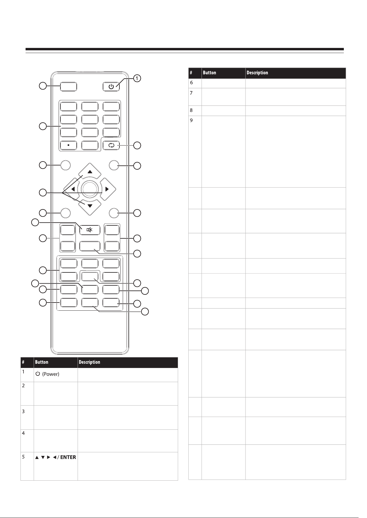
Remote control
Remote Control Unit
10
INPUT POWER
2
1
4
2
5
3
6
3
7
8
0
9
RECALL
13
MENU
MUTE
VOL+/VOL–
VIDEO/HDMI/TV
COMP/VGA
Press to open the on-screen menu.
Press to turn off the sound. Press again to
turn on the sound.
Press to increase or decrease the volume.
Press to select the input source.
• Press VIDEO once to select AV1, twice to
select AV2, three times to select S-Video1,
and four times to select S-Video2.
• Press HDMI once to select HDMI1, twice
to select HDMI2, and three times to select
INFO
4
GUIDE
14
HDMI3.
! Press TV to select TV.
! Press COMP once to select Component1
or twice to select Component2.
! Press VGA to select VGA.
5
MENU
6
7
VOL+
8
VOL- CH
ENTER
MUTE
FAVOR IT E
EXIT
CH
15
<
16
<
10
11
12
SLEEP
ZOOM
PICTURE
Press to set the sleep timer.
Press to select the aspect ratio.
Press to select the picture mode.
17
11
VIDEO
9
COMP
ZOO M
HDMI
MTS/SAP
SLEEP
TV
VGA
CH-LIST
18
19
13
14
RECALL
GUIDE
Press to go to the last viewed channel.
Press to open the DTV program guide (if
available).
12
PICTURE
INPUT
Numbers/Dot(.)
INFO
AUDIO
CCD
20
21
Press to turn on your TV. Press again to put
your TV in Standby mode.
Press to open the INPUT SOURCE menu,
then press 5 or 6 to select the video input
source.
Press to enter channel numbers or the
parental control password. Press the dot
button to select a digital sub-channel.
Press to display the information banner.
Press direction buttons to navigate in the onscreen menus. Press ENTER to confirm
selections in an on-screen menu or to open a
submenu.
15
16
17
18
19
20
21
EXIT
<
CH /CH
FAVORITE
MTS/SAP
CH-LIST
CCD
AUDIO
<
Press to close the on-screen menu.
Press to go to the next or previous channel in
the channel list.
Press to display the favorite channel list.
Press to select the audio mode. For analog
channels, you can select STEREO, SAP
(secondary audio program), or MONO. For
digital channels, you can select the audio
track (if more than one track is available).
Press to open the channel list.
Press to turn closed captioning on or off.
Press to select the sound mode.
2
Page 4
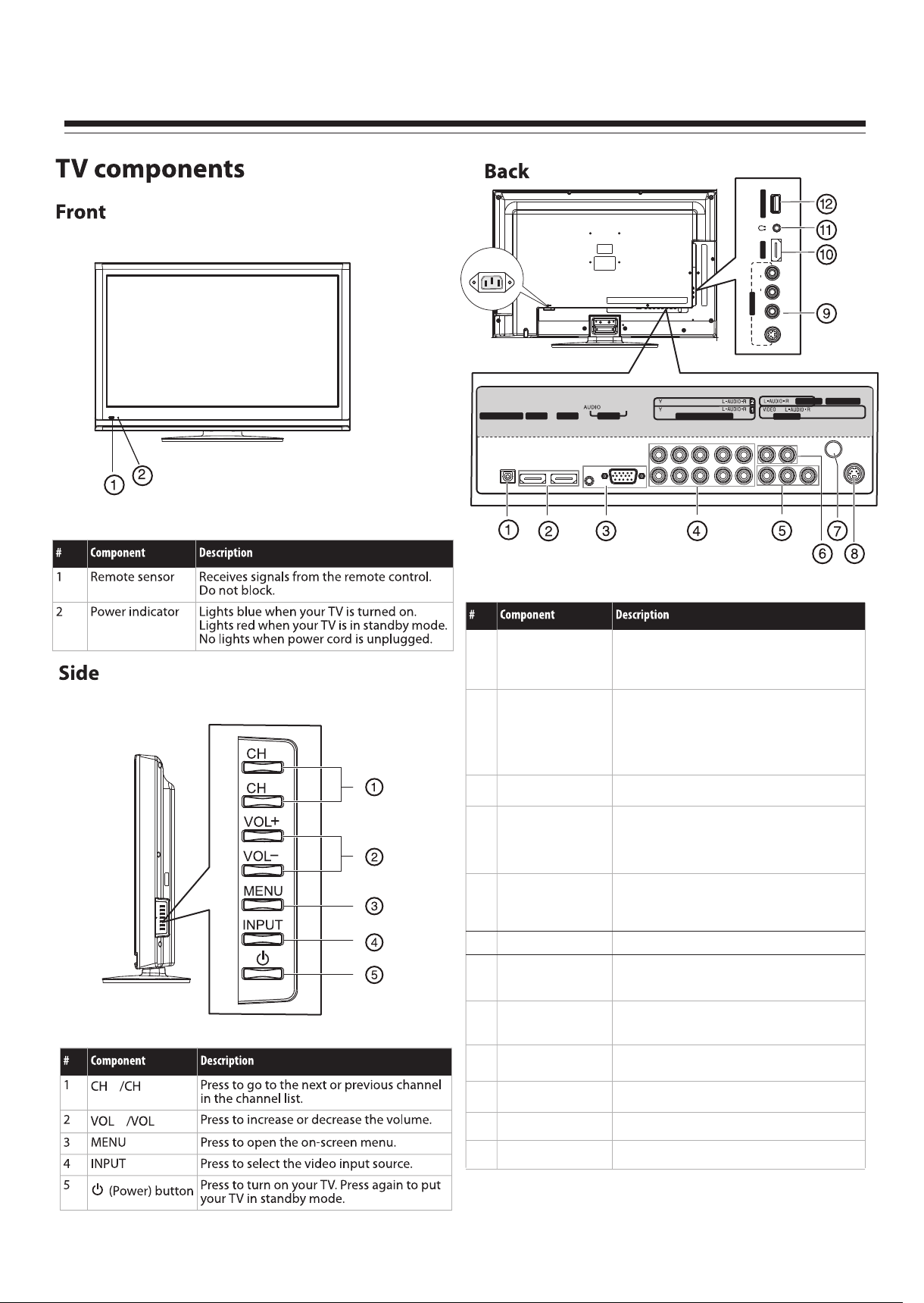
Main Unit (Front View/Side View/Rear View)
SERVI CE PORT
32” model is used in the main unit
for illustration purposes.
AC IN
DIGI TAL OUTP UT
DIGITAL OUTPUT
1
jack
HDMI 3
R
AUDIO
L
AV2 IN
VIDEO
S-VIDEO2
ANT/ C ABLE IN
AV1 IN
AUDI O OUT
S-VID EO1
VGA
PC IN
HDMI 1HDMI 2
PB PR
PB PR
COMP ONENT IN
Connect this jack to a digital sound system to
play your TV’s audio through the sound system.
<
Connect an HDMI device, such as a cable box or
DVD player, to these jacks. An HDMI cable
carries both video and audio, so you do not
need to make an audio connection.
Connect a computer to these jacks. For more
information, see “Connecting a computer” on page 10.
Connect a component video device to these jacks.
The top row of jacks is COMPONENT 2, and the
bottom row of jacks is COMPONENT 1.
Connect an AV device (video and audio) to these
jacks. Match the color of the connectors to the
<
<
2
HDMI2/HDMI1
jacks
PC IN VGA/AUDIO jacks
3
COMPONENT IN 1
4
COMPONENT IN 2
jacks
AV1 IN jack
5
color of the jacks (yellow for video, red for audio
right, and white for audio left).
6
AUDIO OUT jack
7
ANT/CABLE IN jack
8
S-VIDEO1 IN jack
Connect an audio amplifier to these jacks.
Connect an antenna, cable TV, or a satellite box to
this jack.
Connect an S-Video device to this jack, then
connect an audio cable to the AV1 IN AUDIO-L
and AUDIO-R jacks.
AV2/S-VIDEO2 IN
9
jack
<
-
+
10
HDMI3 jack
Headphone jack
11
Connect an AV or S-Video device to these jacks,
then connect audio cables to the audio jacks.
Connect an HDMI device, such as a cable box or
DVD player, to this jack.
Plug headphones into this jack.
12
3
SERVICE PORT
For software update only. Do not use.
Page 5
SPECIFICATIONS
Type: LCD TV
Panel: 32” (DX-32L150A11) TFT LCD
TV system: NTSC-M, ATSC
Receiving Channel: VHF 2-13, UHF 14-69, CATV 1-125, CADTV 1-135, DTV 2-69
Audio multiplex: BTSC System
Audio out: 8W × 2
Power Requirement: AC 120 V, 60 Hz
Power Consumption: 98 W
Dimensions (W x H x D, with stand): 776 ×546 ×210 mm
Weight: 10.5 kg
Terminals:
Composite Video/Audio(L/R): 2
S-Video: 2
Component Video/Audio(L/R): 2
IN
HDMI interface: 3
VGA/Audio: 1
Antenna: 1
Audio(L/R): 1
Digital output: 1
OUT
Headphone jack: 1
Service Port: 1
CONTROL
Note:
1. Design and specifications are subject to change without notice.
2. Weight and dimensions shown are approximate.
3. Specifications and external appearance may be changed for the sake of improvement.
4
Page 6
ALIGNMENT INSTRUCTIONS
1. Test equipment
VG848 (YPbPr, VGA signal generator)
VG849 (HDMI signal generator)
CA210 (color analyzer)
2. Alignment procedure
2.1 Connect all the boards according to wiring diagram. Connect the power supply and
presss “standby” to turn on the TV.
2.1.1 For 32” /37” /42”/46” model
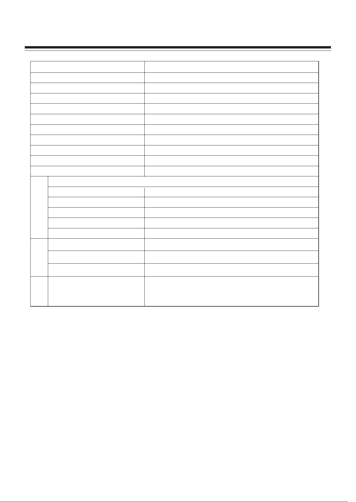
a) In turn measure X508 all pins voltage on Power Board, the value is shown below (Table 1):
Table 1 X508 all pin voltage
Pin 1 2 3 4, 5 6, 7 8 9 10 11 12 13
Min.(V) 4.85 3.25 0 11.3 0 0 4.85 0 4.85 0 2.85
Typical(V) 5.00 3.30 0 12.0 0 0 5.00 0 5.00 0 3.00
Max.(V) 5.35 3.30 0 12.6 0 0 5.35 0 5.35 0 3.15
b) In turn measure X505 all pins voltage on Power Board, the value is shown below (Table 2):
Table 2 X505 all pin voltage
Pin 1, 2 3, 4, 5
Min.(V) 23.8 0
Typical(V) 24.0 0
Max.(V) 25.2 0
c) In turn measure X503 all pins voltage on Power Board, the value is shown below (Table 3):
Table 3 X503 all pin voltage
Pin 1~5 6~10 11 12
Min.(V) 23.8 0 3.25 4.85
Typical(V) 24.0 0 3.30 5.0
Max.(V) 25.2 0 3.30 5.35
2.1.2 For 26” model
a) In turn measure X505 all pins voltage on Power Board, the value is shown below (Table 4):
Table 4 X505 all pin voltage
Pin 1 2 3 4, 5 6, 7 8 9 10 11 12 13
Min. (V) 4.85 3.25 0 11.3 0 0 4.85 0 4.85 0 2.85
Typical(V) 5.00 3.30 0 12.0 0 0 5.00 0 5.00 0 3.00
Max. (V) 5.35 3.30 0 12.6 0 0 5.35 0 5.35 0 3.15
b) In turn measure X503 all pin voltage on the Power Board, the value is shown below (Table 5):
Table 5 X503 all pin voltage
Pin 1, 2 3, 4, 5
Min. (V) 21.6 0
Typical (V) 24.0 0
Max. (V) 26.4 0
c) In turn measure X502 all pin voltage in Main Board, the value is shown below (Table 6):
Table 6 X502 all pin voltage
Pin 1~5 6~10 11 12
Min.(V) 21.6 0 3.25 4.85
Typical(V) 24.0 0 3.40 5.0
Max.(V) 26.4 0 3.60 5.35
5
Page 7
ALIGNMENT INSTRUCTIONS
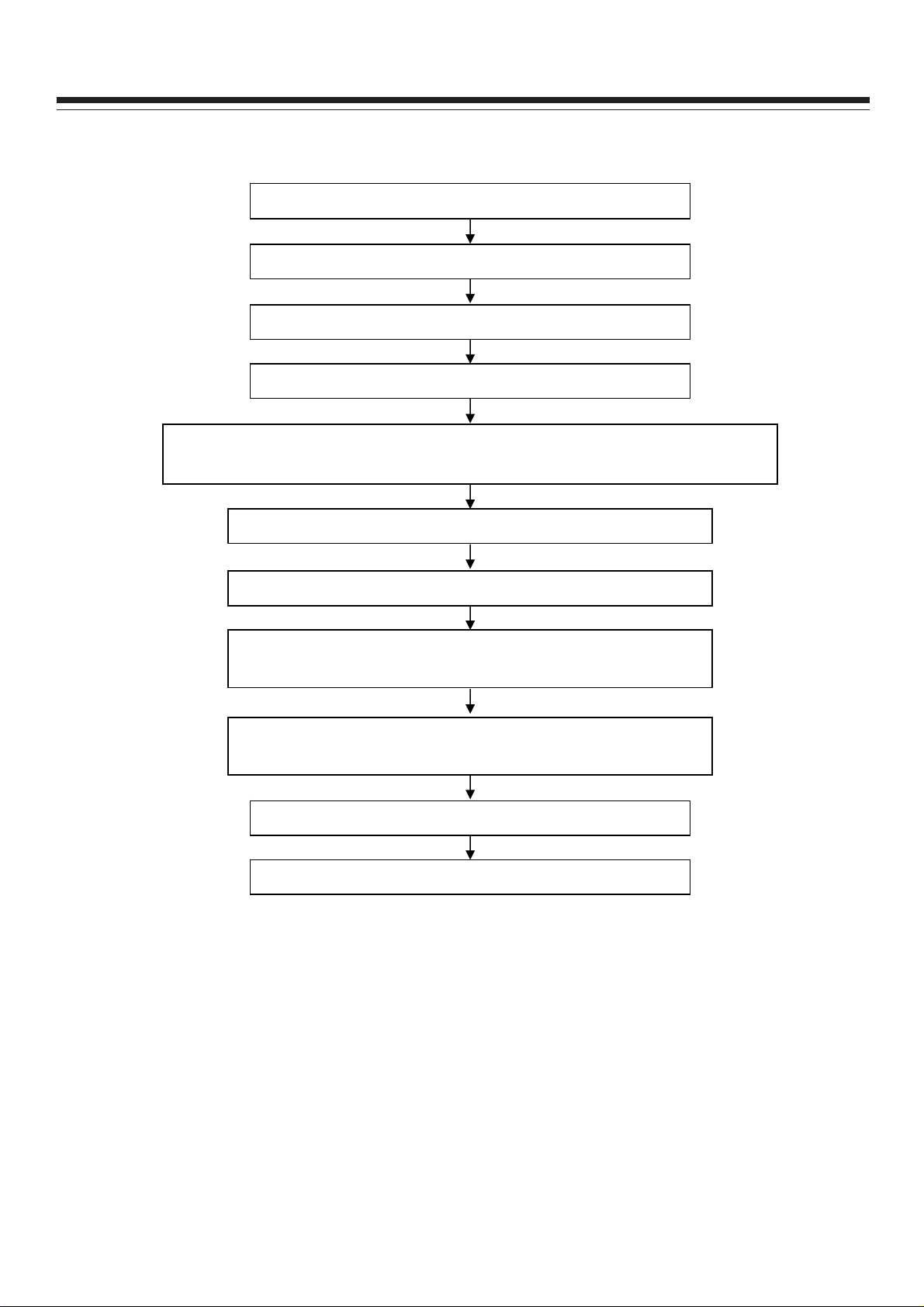
2.2 Alignment flow-chart
The alignment flow-chart is shown below (Fig. 1) :
Check if DDC, FLASH is written?
Make Data Processing Board
Mounting alignment (Check if the voltage is 120V)
White balance alignment
Input test signal, check TV all performance (such as all programs are searched,
analog control, etc.). Check if headphone and speaker output normally.
Input AV/SVIDEO signal, check if the AV jacks perform normally.
Input HD signal, check if YPbPr jacks perform normally.
Input VGA signal, check if the display is normal. Check all
performance (analog control), H-center, V-center, etc.
Input HDMI signal, check if the display is normal. Check all
performance (analog control), H-center, V-center, etc.
Ex-factory preset
Check accessories, packing
Fig.1 Alignment flow-chart
3. Alignment instructions
3.1 The whole unit alignment
3.1.1 According to the wiring diagram, connect Data Process Board, Power Board, Key board, IR
Board. Connect AC 120V power and turn on the TV, check if the display is normal.
3.1.2 The way to use Factory Menu
a) Press INPUT button, then in turn press “2”, “5”, “8”, “0” to enter the Factory Menu.
b) Press CH+ or CH- to select items, then press OK to enter.
c) Press CH+ or CH- to move the highlight up or down.
d) Press VOL- or VOL+ to adjust the selected item.
e) Press MENU to return to the previous menu.
f) Press EXIT to close the Factory Menu.
6
Page 8
g) After closing the Factory menu, you can press SLEEP to enter the Factory Menu directly if power
is still on.
h) In Factory Menu, select “On” for “Aging Mode” to turn on aging mode. Press any button on the unit
to exit.
i) “Power on mode” item of “Otherseting” has three options: “On” means power on directly; “Off”
means the unit will be in “standby” state when connect the power supply, and needed to press
“power” button to turn on; “Memory” means the unit will in the last power-off state after power-on.
3.2 White balance adjustment
3.2.1 Preparations
Before white balance adjustment, let the TV work for more than 30 minutes and be in stable status.
Use Color Analyzer CA210 BBY channel for alignment. Only align NORMAL color temperature. To
ensure both COOL and WARM color temperature to be able to meet the requirements, please make
sure bright step color temperature to be △X≤±5,△Y≤±5, dark step color temperature to be
△X≤±5,△Y≤±5. Below table shows the color temperature for all models:
Model Cool Normal Warm
26”/32”/37”/42”/46” 12000K (272,278) 9300K (285,293) 6500K (313,329)
ALIGNMENT INSTRUCTIONS
Table 7 Color temperature for all models
Below white balance adjustment takes 42” model as an example. For other models, use the above
data as a reference for alignment.
3.2.2 White balance data alignment at four modes
a) Alignment at ATV mode (AV and S-VIDEO is the same)
In TV mode, set Air/Cable to Air. Input test signal with 11 gray steps. From Factory menu select “Color
Temp” item and set “Color Mode” to “NORMAL”, fix GAIN GREEN, adjust GAIN RED and GAIN BLUE
to make 9th step color coordinate to be (285, 293). Fix OFFSET GREEN, adjust OFFSET RED and
OFFSET BLUE to make the third step color coordinate to be (285,293). In this way repeatedly adjust
GAIN RED, GAIN BLUE and OFFSET RED, OFFSET BLUE until two level gray step’s color
coordinate be (285,293). Then select “MENU” to return to previous menu or select “SAVE TO
EEPROM” to save the white balance.
Check if COOL and WARM color temperature meet the requirement. If not, then adjust GAIN RED,
GAIN BLUE, OFFSET RED, OFFSET BLUE to make them meet requirements, and then save.
b) Alignment at DTV mode (HDMI is the same)
In TV mode, set Air/Cable to Air. Input test signal with 11 gray steps. From Factory menu select “Color
Temp” item and set “Color Mode” to “NORMAL”, fix GAIN GREEN, adjust GAIN RED and GAIN BLUE
to make 9th step color coordinate to be (285, 293). Fix OFFSET GREEN, adjust OFFSET RED and
OFFSET BLUE to make the third step color coordinate to be (285,293). In this way repeatedly adjust
GAIN RED, GAIN BLUE and OFFSET RED, OFFSET BLUE until two level gray step’s color
coordinate be (285,293). Then select “MENU” to return to previous menu or select “SAVE TO
EEPROM” to save the white balance.
Check if COOL and WARM color temperature meet the requirement. If not, then adjust GAIN RED,
GAIN BLUE, OFFSET RED, OFFSET BLUE to make them meet requirements, and then save.
7
Page 9

c) Alignment at YPbPr mode
First perform ADC calibration: input 75% color bar plus gray step signal in 480i/60Hz format, (VG848
Timing is 968, PAT is 918), enter Factory Menu select ADC Setting, do ADC AUTO adjustment once.
White balance adjustment: From VG848 equipment input 8 gray steps signal in 1920 x 1080i /60Hz
format. Enter Factory Menu select “Color Temp”, first set “Color Mode” to NORMAL, fix GAIN GREEN,
adjust GAIN RED and GAIN BLUE to make the 7th color coordinate be (285, 293). Fix OFFSET
GREEN, adjust OFFSET RED and OFFSET BLUE to make the second step color coordinate be (285,
293). In this way repeatedly adjust GAIN RED, GAIN BLUE and OFFSET RED, OFFSET BLUE until
two level gray step color coordinate be (285, 293). Then select “MENU” to return to previous menu or
select “SAVE TO EEPROM” to save the white balance.
Check if COOL and WARM color temperature meet the requirement. If not, then adjust GAIN RED,
GAIN BLUE, OFFSET RED, OFFSET BLUE to make them meet requirements, and then save.
d) Alignment at VGA mode
First do ADC calibration: input VESA crosshatch signal in 800 x 600 / 60Hz format (VG848 Timing is
854, PAT is 914), check if the picture is displayed wholly. If not, perform AUTO adjustment by making
use of VGA Setting sub-menu from SETUP menu (User menu) so that the picture is displayed wholly.
Then enter Factory Menu select ADC Setting, do ADC AUTO adjustment once to calibrate ADC.
White balance adjustment: From VG848 equipment input 8 gray steps signal in 800 x 600 /60Hz
format. Enter Factory Menu select “Color Temp”, first set “Color Mode” to NORMAL, fix GAIN GREEN,
adjust GAIN RED and GAIN BLUE to make the 7th color coordinate be (285, 293). Fix OFFSET
GREEN, adjust OFFSET RED and OFFSET BLUE to make the second step color coordinate be (285,
293). In this way repeatedly adjust GAIN RED, GAIN BLUE and OFFSET RED, OFFSET BLUE until
two level gray step color coordinate be (285, 293). Then select “MENU” to return to previous menu or
select “SAVE TO EEPROM” to save the white balance.
Check if COOL and WARM color temperature meet the requirement. If not, then adjust GAIN RED,
GAIN BLUE, OFFSET RED, OFFSET BLUE to make them meet requirements, and then save.
4. Performance check
4.1 TV performance
Input RF signal, first enter into CHANNEL menu, then perform Auto Scan to check if all programs can
be found, the speaker output normally, picture is displayed normally. Pay special attention that both
NTSC and ATSC signals are found.
4.2 Checking AV/S-Video jacks
Respectively input signal from AV/S-VIDEO jacks, check if the picture and sound are normal.
4.3 Checking YPbPr/YCbCr jacks
Input YUV signal (from VG848 signal generator), respectively input all formats of YUV signal which is
shown at below (Table 8) to check if the display and sound are normal.
ALIGNMENT INSTRUCTIONS
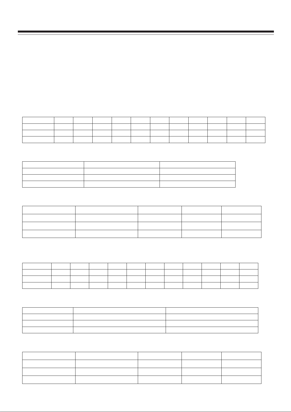
Table 8 YUV signal formats
# Resolution
1 720×480i@59.94/60 Hz 15.734 59.94/60 13.5 480i(59.94/60p)
2 720×480p@59.94/60 Hz 31.469 59.94/60 27.00 480p(59.94/60p)
3 1280×720p@59.94/60 Hz 44.96 59.94 74.18 720p(59.94/60p)
H-freq.
(kHz)
V-freq.
(Hz)
8
Dot-Clk Freq.
(MHz)
Remarks
Page 10
ALIGNMENT INSTRUCTIONS
4 1920×1080i@59.94/60 Hz 33.75 59.94 74.25 1080i(59.94/60i)
5 1920×1080p@23.98/24 Hz 27.00 23.98/24 74.25 1080p(23.98/24p)
6 1920×1080p@59.94/60 Hz 67.50 60.00 148.50 1080p(59.94/60p)
4.4 Checking VGA jack
Input VGA signal (VG848 signal generator),respectively input all formats of VGA signal which is
shown below (Table 9). Check if the display and sound are normal. If the picture has deflection in size
and position, then enter into user menu of Setup, from VGA Setting sub-menu perform AUTO
adjustment to correct the picture automatically.
Table 9 VGA signal formats
# Resolution H-fre. (kHz) V-fre. (Hz)
720×400@70 Hz 31.47 70.08 28.32 DOS
1
640×480@60 Hz 31.50 60.00 25.18 VESA
2
800×600@60 Hz 37.90 60.00 40.00 VESA
3
1024×768@60 Hz 48.40 60.00 65.00 VESA
4
1280×1024@60 Hz 63.98 60.02 108.00 Only for 37”/42”/46” model
5
1360×768@60 Hz 47.71 60.01 85.50 Only for 26” and 32” model
6
1920×1080@60 Hz 67.16 59.96 173.00 Only for 37”/42”/46” model
7
Dot-CLK
freq. (MHz)
Remarks
4.5 Checking HDMI jack
Input HDMI signal (VG849 signal generator), respectively input all formats of signal shown at Table 8.
Check if the display and sound are normal.
5 User menu preset
Enter into Factory menu, select and do Other Setting→SHIPMENT item, then the TV will automaticlly
preset the user menu to default. After alignment this User Menu Preset procedure must be done.
SHIPMENT will do the following :
1) Clear all program information
2) Clear V-CHIP information
3) Analog value default setting for all sources
4) Power on mode set to Off
5) Active Setup Wizard menu
Note: after the Preset procedure is complete, it must exit the menu, power off at Standby state and
then disconnect the power supply.
6. Software writing instructions are shown at below (Table 10)
Table 10 Software writing instructions
# Part No. Model
NS04 5272532005 MX25L3205DM2C-12G
NS03 5272404002 AT24C04IV-10SU-2.7
Software
function
Main
software
HDCP
KEY
Method Remarks
Write with instrument like
ALL11. Write-protection is
needed.(See below note)
Write with instrument like
ALL11
For all models
For all models
NB01 5272402002 AT24C02BN10SU-1.8 VGA EDID
NA05 5272402002 AT24C02BN10SU-1.8
HDMI1
EDID
9
Write with instrument like
ALL11
Write with instrument like
ALL11
For all models
Only for
32”/37”/42”/46”
models
Page 11

ALIGNMENT INSTRUCTIONS
Only for
32”/37”/42”/46”
models
Only for 26”
model
NA04 5272402002 AT24C02BN10SU-1.8
NA07 5272402002 AT24C02BN10SU-1.8
NA04 5272402002 AT24C02BN10SU-1.8
NA07 5272402002 AT24C02BN10SU-1.8
HDMI2
EDID
HDMI3
EDID
HDMI1
EDID
HDMI2
EDID
Write with instrument like
ALL11
Write with instrument like
ALL11
Write with instrument like
ALL11
Write with instrument like
ALL11
Note:
To set write protection, the method is : enter into ALL-100 writing program AUTO interface, select
Config item (it must be selected when writing). In AUTO interface, click Config Setting, set Protect to
All Protect, SRWD to Enable. Pay attention that every time when ALL-100 writing program is
reopened, write-protection must be set again.
7. EEPROM initialization (not be used unless needed)
The method is: press IR POWER/KEYPAD POWER to turn on the TV, before showing LOGO press
INPUT SOURCE incessantly until the indicator lights red, then in turn press MENU, VOL+, CH+ (the
interval between two press is below 2 seconds), the indicator light will turn blue, after a while the unit
will be in STANDBY, that means RESET EEPROM succeeds. If error key order or key number or the
interval is over 2 seconds, the unit will keep on the previous setting and perform the order, then
EEPROM will not be cleared
10
Page 12

This series’ TV chassis provides two software upgrade ports, one is SERVICE PORT, the other is
RS232 jack. To use SERVICE PORT, only a USB device is required and the speed is faster, so it is
recommended to use the SERVICE PORT. To use RS232 jack, the speed is slower, and more devices
are required such as a PC, a set of fixture for upgrade and upgrade software. It is recommended that
only SERVICE PORT fails in upgrade, then use RS232 jack.
Software Update Instructions
A. Making use of SERVICE PORT for upgrade
Copy file with extension name of BIN (*.BIN) for upgrade to the USB device, save it at root catalog. To
upgrade different TV model, the adopted files are different. It is required to correctly name the *.BIN
files, and below table lists the TV models and file names for your reference.
Model Panel type Part No. Software name
DX-19L150A11 CPT 9219KS7001 LC19KS70CPT.BIN
DX-22L150A11 CPT 9222KS7001 LC22KS70CPT.BIN
DX-24L150A11 CMO 9224KS7001 LC24KS70CMO.BIN
DX-26L150A11 AUO 9226KS7001 LC26KS70AUO.BIN
DX-32L150A11 AUO 9232KS7001 LC32KS70AUO.BIN
DX-37L150A11 AUO 9237KS7001 LC37KS70AUO.BIN
DX-40L130A11 SHARP 9240KS7001 LC40KS70SHARP.BIN
DX-46L150A11 AUO 9246KS7001 LC46KS70AUO.BIN
Method 1:
1. Disconnect the AC power, insert USB device into the SERVICE PORT.
2. Reconnect the power, the TV will automatically upgrade the software. It will take some minutes.
During the process, the power indicator will flicker in red and blue. After completion, the TV will auto
power on and the power indicator lights blue. If the process takes more than 5 minutes, that means the
upgrade fails. Please check the BIN format file and USB device again.
3.When upgrade completed, remove the USB device, disconnect the AC power and then reconnect
the power. The SERVICE PORT upgrade is finished completely.
Method 2:
1. Connect the power. Insert the USB device into the SERVICE PORT.
2. Enter into Factory menu, access SW Upgrade option. The TV will automatically scan the USB
device and files in BIN format. If USB device is normal and BIN file is correct, the TV will upgrade by
itself. If fails, then check BIN file and USB device again.
3. When upgrade completed, remove the USB device, disconnect the AC power and then reconnect
the power. The SERVICE PORT upgrade is finished completely.
11
Page 13

Software Update Instructions
B. Making use of RS232 for upgrade
Tips: A PC and the upgrade fixture designed for this KS# chassis are required. Use Mstar on-line
writing tool – Mstar ISP Utility, the needed time is longer.
1. Power on the TV, connect the upgrade fixture correctly, open the upgrade software, click “Connect”
icon. If the connection fails, the following screen will appear.
2. Click “Config” icon (see below figure). Adjust “ I2C Speed Setting” option, lower the setting of
“Speed”. Then click “Connect” icon again.
Wait until right connection information appears which is shown below.
12
Page 14

3. Click “OK” , then click “Device” (see below figure).
Software Update Instructions
Mark “WP Pin pull to high during ISP” option.
Mark “New Setting Below” option.
Mark Bit7,Bit5,Bit4,Bit3,Bit2 from “Status Register” option. That is, the value of “Register Setting
Value” should be “BC”.
4. Click “Read” icon, download upgrade software which is shown below.
13
Page 15

5. Click “Auto” .
Software Update Instructions
Mark “Erase Device” option, select “File Area”.
Mark “Blank”, “Program”, “Verify”, “Exit ISP” options.
Click “Run” button, on the right will appear information of upgrade hints. When “Pass” appears, that
means the upgrade is successful.
6. After completion, disconnect the power then reconnect it. The upgrade is finished now.
14
Page 16

The analog and digital RF signal received by antenna will be sent to integrative tuner
TUNER2(DA58GT-13-E, contains HF and IF amplifier circuits), which selects appropriate channel and
sends the selected IF signal to the next level by the control of SDA, SCL.
The analog RF signal sent to tuner, via high amplify and mixed frequency to get IF signal VIF,
then it will be divided into two ways, one way will be sent to acoustic surface-wave ZF3 to IF filter and
get better IF characteristics, then it will be sent to NF1(M61111FP) through pin20, 21 to do
intermediate amplification, phase-locked loop VCO and synchronous wave detection and output
VIDEO-TV(ATV) from pin1; another way will be sent to acoustic surface-wave ZF4 to IF filter and gent
better IF characteristics, then it will be sent to NF1(M61111FP) to do intermediate amplification
and wave detection and output SIF from pin10.
The digital RF via high amplify and mixed frequency in the tuner, output deferential digital IF
signal from pin10、11, the signal will be sent to the main IC NS01(MSD319EL) to do intermediate
amplification and demodulation, then demodulate the transform stream TS which contains video/audio
Working Principle Analysis of The Unit
and other information.
ATV, SIF, TS, audio/video signal of AV, S-VIDEO, VGA and HDMI. Component video signal
selected by switch NB09(PI5V330W) from Component 1 and Component 2, Then one of video signal
selected by switch NB10(PI5V330W) from Component and VGA . AV, S-VIDEO ,Component audio
signal selected by switch NB11 (HEF4052BT), HDMI audio/video signal selected by internal switch
from HDMI1, HDMI2, HDMI3; all of the signals will be sent to the main IC NS01(MSD319EL) switch
select, video decode and process.
In MSD319EL, TS of DTV via TS demultiplex, distinguish the different programs and pick-up the
corresponding audio/video stream and data stream, after MPEG-2 uncompress, video coder and
audio D/A transform, recover the analog video signal YCbCr and audio signal L/R.
ATV output from M61111FP will be sent to MSD319EL video switch, A/D convert and digital
decode. The video selected by switch embed in MSD319EL will be sent out in two ways: one is sent to
decode and process; the other is Video OUT.
All of the video data (include DTV video) via switch select, video decode and process will be
sent to MSD319EL to do D/A transition, image scale, OSD superposition, then LVDS conversion to
signal acceptable for LCD panel, namely four pairs of low differential signal and one pair of clock
signal, then it will be sent to LCD panel for picture display.
All of the audio signals will be sent to MSD319EL to do audio switch selection and sound effect
processing, then output L/R to sound amplifier NV03 (R2S15112FP) amplifying to speaker. The audio
L/R also sends to Audio OUT.
The unit is control by the MCU built in MSD319EL, it connects TUNER and E2PROM through
IIC bus line and controls the whole unit working.
15
Page 17

Block Diagram
POWER
12V、5V、3.3V、1.8V、1.2V、STB5.0V
12V、5V、3.3V、1.8V、1.2V、STB5.0V
POWER
VGA AUDIO
VGA AUDIO
OTHER AUDIO
OTHER AUDIO
INPUTS
INPUTS
TNUER
TNUER
FA2316
FA2316
AUDIO SWITCH
AUDIO SWITCH
IF
IF
ANOLOG DEMO
ANOLOG DEMO
HEF4052BT
HEF4052BT
M61111FP
M61111FP
DIF
AV 1
AV 1
AV 2
AV 2
SVIDEO 1
SVIDEO 1
SVIDEO 2
SVIDEO 2
YPbPr 1
YPbPr 1
YPbPr 2
YPbPr 2
VGA
VGA
HDMI 1
HDMI 1
HDMI 2
HDMI 2
HDMI 3
HDMI 3
YPbPr
YPbPr
YPbPr
YPbPr
RGB
RGB
VIDEO SWITCH
VIDEO SWITCH
PI5V330W
PI5V330W
VIDEO SWITCH
PI5V330W
VIDEO SWITCH
PI5V330W
IIC
DIF
IIC
DDR SDRAM
DDR SDRAM
K4T51163QG-HCF7
K4T51163QG-HCF7
AUDIO
AUDIO
CVBS
CVBS
SIF
SIF
Video
Video
Y-C
Y-C
RGB
RGB
MX25L3205DM2C-12G
MSD319EL
MSD319EL
16
SPI FLASH
SPI FLASH
MX25L3205DM2C-12G
LVDS
LVDS
IIC
HP AMP
BH3547F
HP AMP
BH3547F
Panel
HDCP KEY
IIC
AT24C04IV
HP AMP
R2S15112PF
BH3547F
SERVICE PORT
HP AMP
BH3547F
Panel
AMP
HP
RS232
Audio out
Video out
SPDIF
HDCP KEY
SPEAKER
AT24C04IV
AMP
R2S15112PF
HP
SERVICE PORT
RS232
Audio out
Video out
SPDIF
SPEAKER
Page 18

1. no picture and no sound
Connect the power and
check if the red
indicator lights at
STANDBY?
Y
N
Check if 5V of X603
3# on the main board
inputs normally?
N
N
Check STANDBY
circuit on the power
board
TROUBLESHOOTING GUIDES
Press POWER button
on the unit or remote
control, does the
indicator turn blue?
N
Check if the voltage of
X601 pin1 on the main
board is high?
Check the power board
N
Y
Check if the voltage of
Y Y N
X601 pin13 on the
main board is high?
N
Check NS01 and its
Y
peripheric circuit
Is 24V on the power
board normal?
Y
Check the backlight
board
Check the power board
17
Page 19

2. no picture
Replace the main
board
N
TROUBLESHOOTING GUIDES
Replace the main
board
Initialize EEPROM in
N
factory menu, then power
off, check if picture is
normal after restart?
N
N
Y
No picture
Y
Can the unit be operated
by remote control or
keys on the set?
Y
Is there any backlight?
Y
N
Display OSD normally
when press MENU
button?
Y
Y
No picture from all
sources?
N
Replace the main
Y
board
Is there 24V on the
Y
power board?
Y
IF X601 pin4/pin5 on
main board is
high-level
Y
Check the panel
backlight
N
Check the power board
N
Check the main board
18
Page 20

TROUBLESHOOTING GUIDES
Adjust the main board
again
N
Which channel is no
picture?
TV
Measure NF1 pin1, is
there 1-1.5 VPP signal
or noise wave?
N
Check if the output
from TUN2 pin12 is
normally?
Y
Check NF1 and its
peripheric circuit
OTHER
Y
N
Replace the main
board
Replace the main
board
Check TUN2 and its
peripheric circuit
19
Page 21

3. no sound (take TV as an example)
p
/
p
No sound
Y
Check if the voltage of
X602 pin4/pin5 is
normal?
Check the power board
N
TROUBLESHOOTING GUIDES
Check if there is wave
Y
inputted to NV03
in12
in25?
N
Check if there is wave
outputted from NV01
pin1/ pin7?
N
Check if wave output
from NS01pin63/pin64
is normal?
N
Is there 4.5M wave
inputted from NS01
pin51/pin52?
Y
Y
Y
Y
Check NV03 and its
peripheric circuit
Check NV01 and its
peripheric circuit
Check NS01 and its
peripheric circuit
20
Page 22

TROUBLESHOOTING GUIDES
Is there IF 45.75M
outputtd from
TUNER2 pin12?
Check TUNER2 and
its peripheric circuit
N
Y
Check NF1 and its
peripheric circuit
N
21
Page 23

Wiring Diagram
Page 24

POWER BOARD FOR 32" MODEL
page 1 of 9
Page 25

POWER BOARD FOR 37" MODEL
page 2 of 9
Page 26

POWER BOARD FOR 40" MODEL
page 3 of 9
Page 27

POWER BOARD FOR 46" MODEL
page 4 of 9
Page 28

IR&KEY&TUNER
page5 of 9
Page 29

INTERFACE CIRCUIT (1)
page 6 of 9
Page 30

INTERFACE CIRCUIT (2)
page 7 of 9
Page 31

POWER
page 8 of 9
Page 32

MSD319
page 9 of 9
Page 33

Page 34

Page 35

Exploded View Parts List
 Loading...