

Page 1

XO SMART LINK FOR XO UNITS
USER GUIDE
Page 2

Intended use
Starting XO
XO Smart Link in combination with an XO Unit
gives you the opportunity to:
Work with unit
instrument programs and improve quality of
care.
Manage IT solutions and
external instruments
etc. during the treatment – concentrate on
the work in the mouth of
the patient – avoid cross
contamination – and
avoid extra foot controls
etc.
Configure your unit to
function according to
your personal preferences.
Smart Link
Open the Microsoft
Windows “start” menu /
Programs / “XO CARE” /
“XO Smart Link” / “Start
XO Smart Link”.
For first time start-up
and software licensing please refer to “XO
Smart Link Installation
Gui de”.
2
Page 3
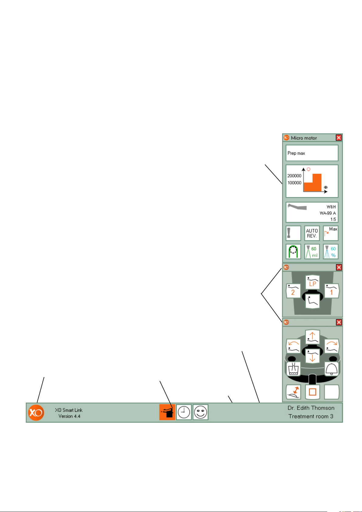
PC screen image
This picture is created for demo purposes. Actual screens may
vary.
Instrument window
Appears automatically
when activating a unit
instrument. The window gives a complete
overview of the active
program
XO Menu
Click on XO logo to
open XO Menu
Installed plug-ins
Right click on a cell
to access the configuration menu
XO Screen User
Guide
Automatically displays
the functions available
Free plug-in space
Right click to add
more plug-ins
XO Bar
Use foot control to
navigate the cells
3
Page 4
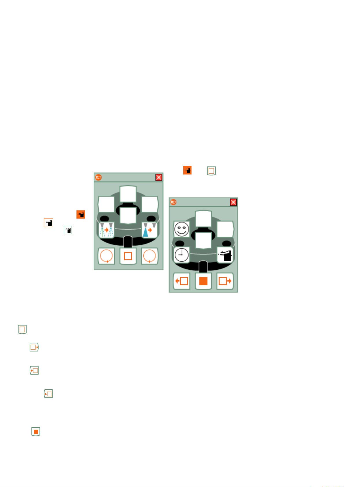
Navigating
XO Screen
Navigating
XO Smart
Link
The main tools for navigating XO Smart Link
are foot control and XO
Bar.
XO Bar contains a number of cells:
• Each cell represents a
plug-in - when all unit
instruments rest.
• Each cell represents a
unit instrument program - when a unit
instrument is
lifted forward.
A cell may be active ,
selected ,
or non selected .
User Guide
Each cell of XO Bar defines the function of foot
control (and joystick).
XO Screen User Guide
shows you the available
functions.
Example of XO Screen
User Guide when using
Micro Motor:
using short-
cuts
When no XO Bar cell is
active shortcuts allow
you to activate
up to 8 different cells:
• With only two foot
control “clicks” and
• Without looking at
the screen.
Deactivate the active
cell with .
Thereafter select a
shortcut:
The active cell defines
the function of foot control (and joystick).
XO Screen User Guide
shows how foot control
(and joystick) functions
in accordance with the
active cell.
Deactivate a cell with
.
Select the rightward cell
with .
Select the leftward cell
with
When the leftmost cell is
selected
the rightmost cell and
vice versa.
.
will select
See page 14 for information about configuring shortcuts.
Activate a selected cell
with .
4
Page 5
Workflows
Program/
Activation
Torque reduc-
XO Smart Link has introduced the ability to use
workflows for XO Osseo
and micro motor.
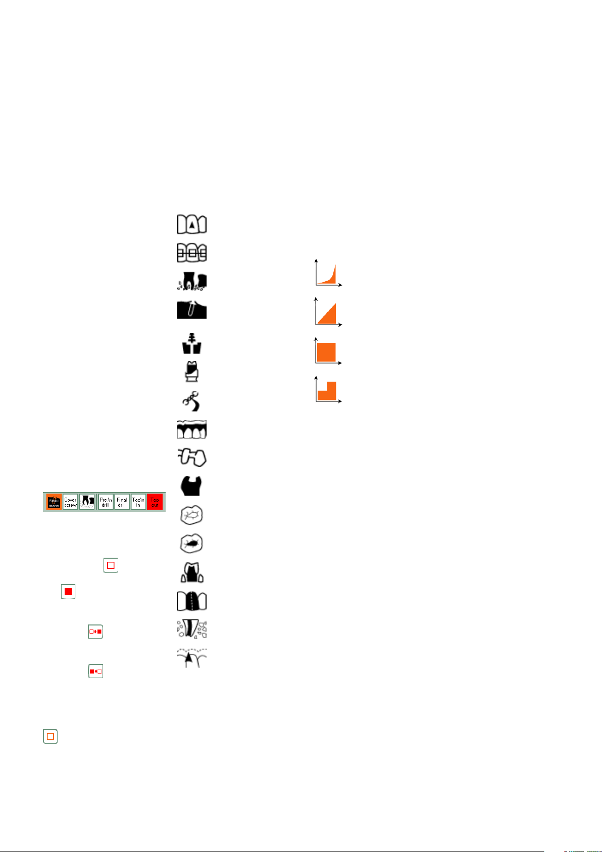
A workflow is a set of
programs (from this
point on referred to as
steps), which may be
sequentially activated
to perform a specific
treatment - for example preparation for an
implant.
Workflows are shown on
XO Bar exactly as other
programs. When you
activate a workflow the
steps will be shown to
the right side of the program list. These steps
have a red background
when selected. Each
workflow can contain a
maximum of ten steps.
Navigating steps in
Workflows:
Deactivate current step
by pressing .
Activate step by pressing .
Go to next step and
activate this step by
pressing .
Go to previous step and
activate this step by
pressing .
Deactivate workflow
(and get back to navigate the programs-/
workflowlist) by pressing
.
workflow
icons
XO Smart Link allows
use of the following
icons in program/ workflow plug-ins:
Prophylaxis
Orthodontics
Jaw surgery
Implantology
Post system
Precision technique
Model casting
technique
Acrylic technique
Crown and
bridge technique
Cavity preparation
Removal of old
fillings
Working on fillings
Crown preparation
Crown cutting
Root canal
preparation
Root planning
curves
Different activation
curves can be used
for: motor, turbine and
scaler instruments. XO
Smart Link gives the
option of 4 different
activation curves:
Exponential
Linear
One step
Two step
tion
When configuring a
specific program or
workflow step of the
attached micro motor(s)
and/or XO OSSEO the
maximum torque may
be reduced.
If the maximum torque
is reduced the absolute
value of the maximum
torque in Ncm is shown
in XO Instrument Window. Please note that
the indicated maximum
torque value is calculated based on XO’s
experience with
efficiency of different
contra angles and is
thus only to be used as
a rough guide line.
5
Page 6
Micro motor
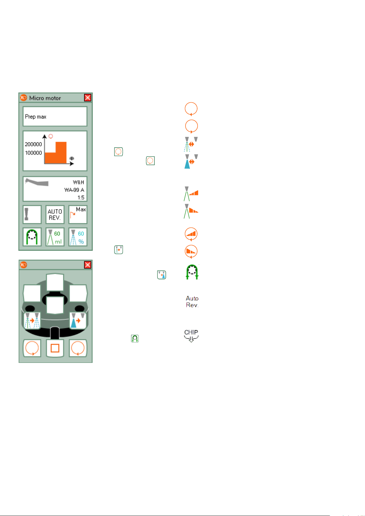
Lift micro motor forward and control it with
foot control.
See relevant data on
screen and display.
Run motor clockwise
with or counter
clockwise with in the
range specified by the
active program.
See maximum speed on
screen and on display
when foot control is not
activated. See actual
speed on display when
motor is running.
Change spray selection
with : water & air, air
only or no spray.
Enable/disable the
automatic chip blow
after stop of motor with
spray water.
As an option the motor
may be configurated to
work with XO Peristal-
tic Pump. is then
shown.
Standard actions
Start rotation
clockwise
Start rotation counter clockwise
Spray selection
Enable / disable XO
Chip Blow
Configurable actions
Increase spray water / irrigation level
Decrease spray
water / irrigation
level
Increase maximum
speed
Decrease maximum
speed
XO Peristaltic
Pump
Enable/disable auto
reverse (motor will
stop and reverse
when maximum
torque level is
reached.)
“Pediel” chip blow
6
Page 7
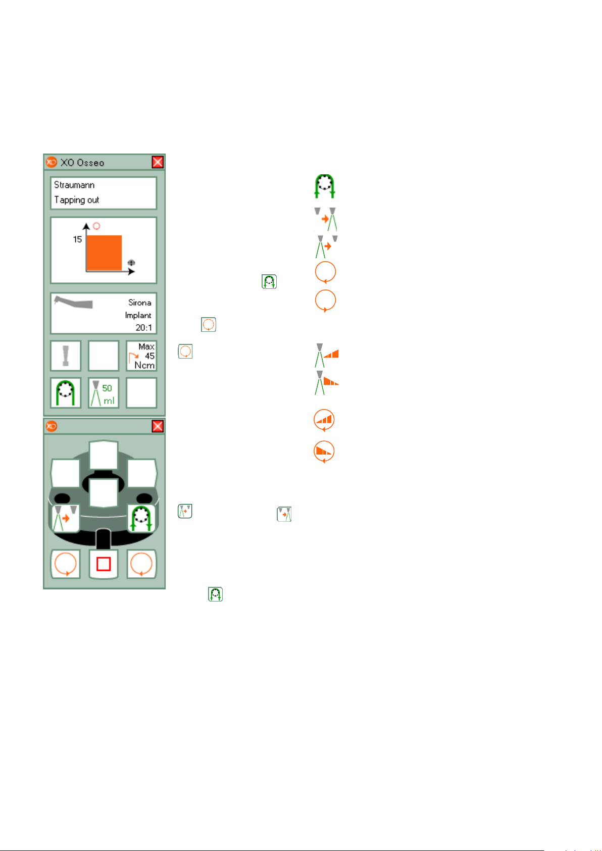
XO OSSEO
Lift XO OSSEO forward and control it with
foot control.
See relevant data on
screen and display.
XO Osseo is configurated to work with XO
Peristaltic Pump
.
Run motor clockwise
with
counter clockwise with
or run motor
in the range specified by the active program.
See maximum speed on
screen and on display
when foot control is not
activated. See actual
speed on display when
motor is running.
Standard actions
Activate XO Peristaltic Pump (without running motor)
Enable irrigation
Disable irrigation
Rotate motor
clockwise
Rotate motor counter clockwise
Configurable actions
Increase irrigation flow
by 5 ml per minute
Decrease irrigation
flow by 5 ml per
minute
Increase maximum
speed level
Decrease maximum speed level
Disable irrigation with
and enable with
.
Activate XO Peristaltic
Pump without having
the XO OSSEO running
for as long as it is activated
.
7
Page 8
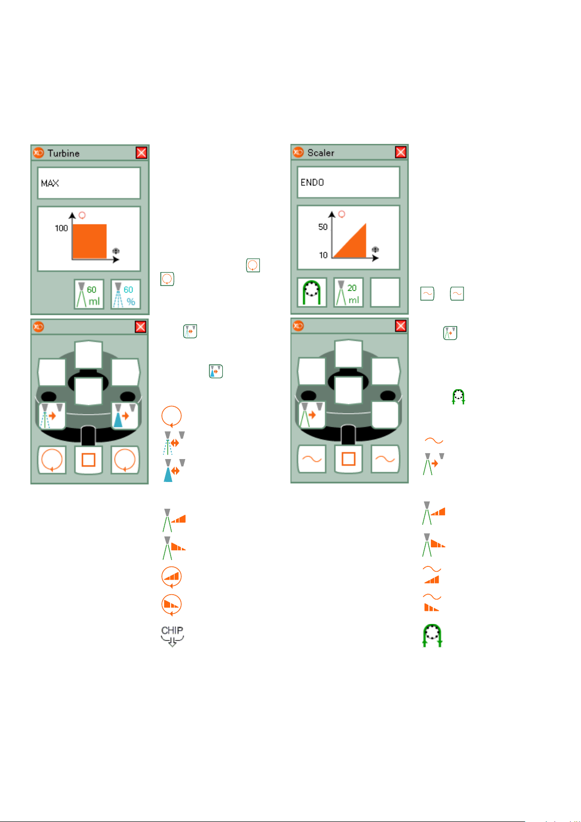
Turbine
Scaler
Lift turbine forward
and control it with foot
control.
See relevant data on
screen and display.
Current speed (in % of
maximum) on display.
Start turbine with or
.
Change spray selection:
water & air or no spray
with .
Enable/disable chip
blow with .
Standard actions
Start turbine
Lift scaler forward and
control it with foot control.
See relevant data on
screen and display. Current power setting (in %
of maximum) on display.
Start/stop oscillation
(power) of scaler with
or .
Switch cooling on/off
with .
As an option the scaler
may be configurated to
work with XO Peristaltic
Pump is then shown.
Standard actions
Spray selection
Enable / disable
chip blow
Configurable actions
Increase spray
water level
Decrease spray
water level
Increase maximum
speed
Decrease maximum
speed
“Pediel” chip blow
Power on
Irrigation on/off
Scaler
Configurable actions
Increase level of
cooling water
Decrease level of
cooling water
Increase power
level
Decrease power
level
Use XO Peristaltic
Pump only while
button is pressed
8
Page 9
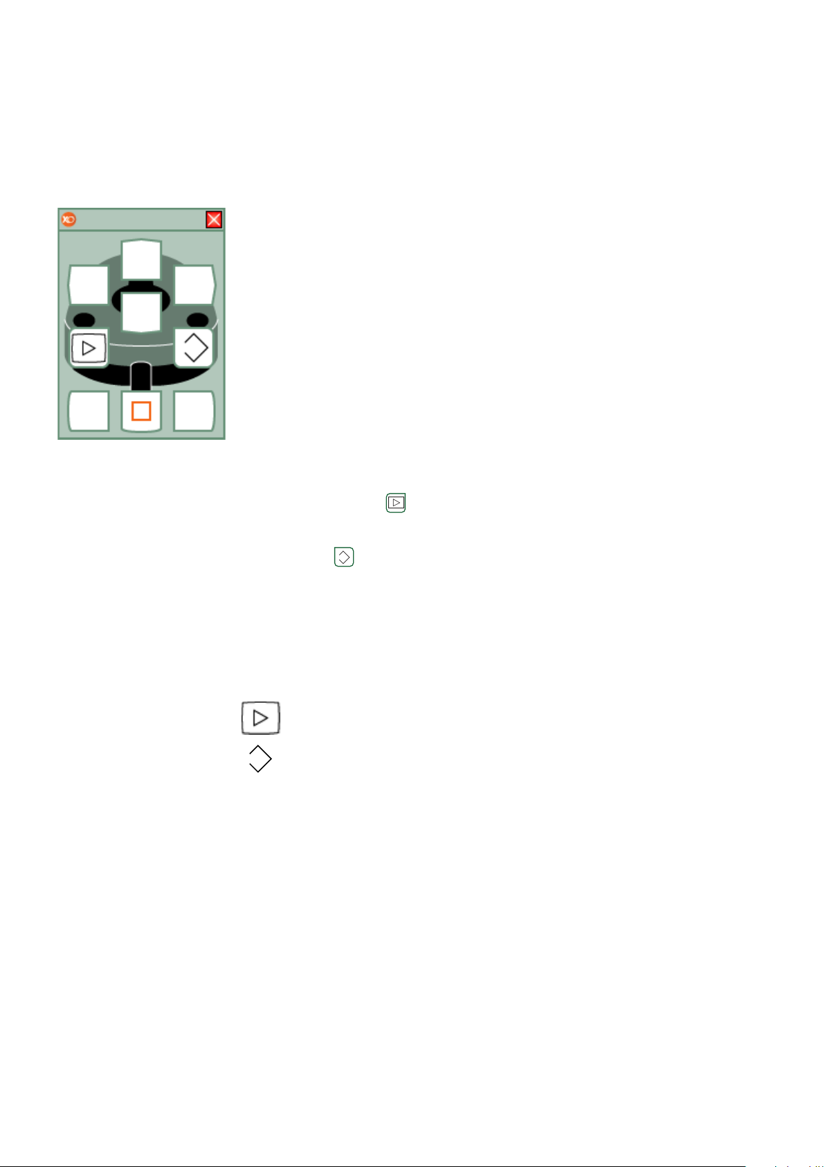
lntraoral video camera
Unlike all other unit
instruments you can use
the video camera even
when another instrument is active.
Lift camera forward and
display a video image
on a screen.
Control video camera
with foot control when
no other instruments are
active.
Toggle between “still”
and “live” mode with .
Save a “still” image to
memory with .
Please note that the
functions available vary
depending on the imaging software used.
Standard actions
Still / Live mode
Video Camera
Save image to
memory - Video
camera
9
Page 10
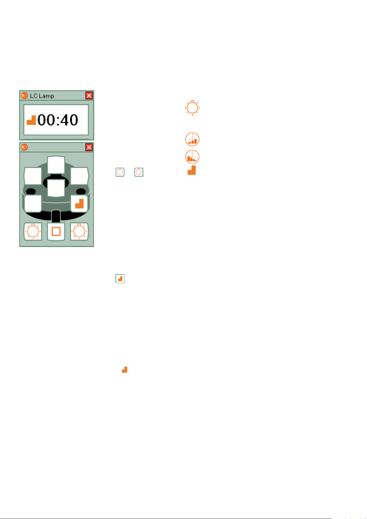
Light curing lamp
Lift light curing lamp
forward and control it
with XO Foot Control.
See current exposure
time on screen and on
display before foot control is activated.
Start curing process
with or .
See elapsed curing time
on screen and display
during the process.
You will hear a beep
after each 5 seconds.
When the curing expires
you will hear a sound.
Enable/disable Softstart
with .
Standard actions
Start LC Lamp
Configurable actions
Increase exposure
time / LC Lamp
Decrease exposure
time / LC Lamp
Softstart
Softstart is a feature
which adds from 1 to
300 seconds to the
selected exposure time.
In the selected time a
reduced power is provided.
When Softstart is enabled,
in the left side of the
display.
will be shown
10
Page 11
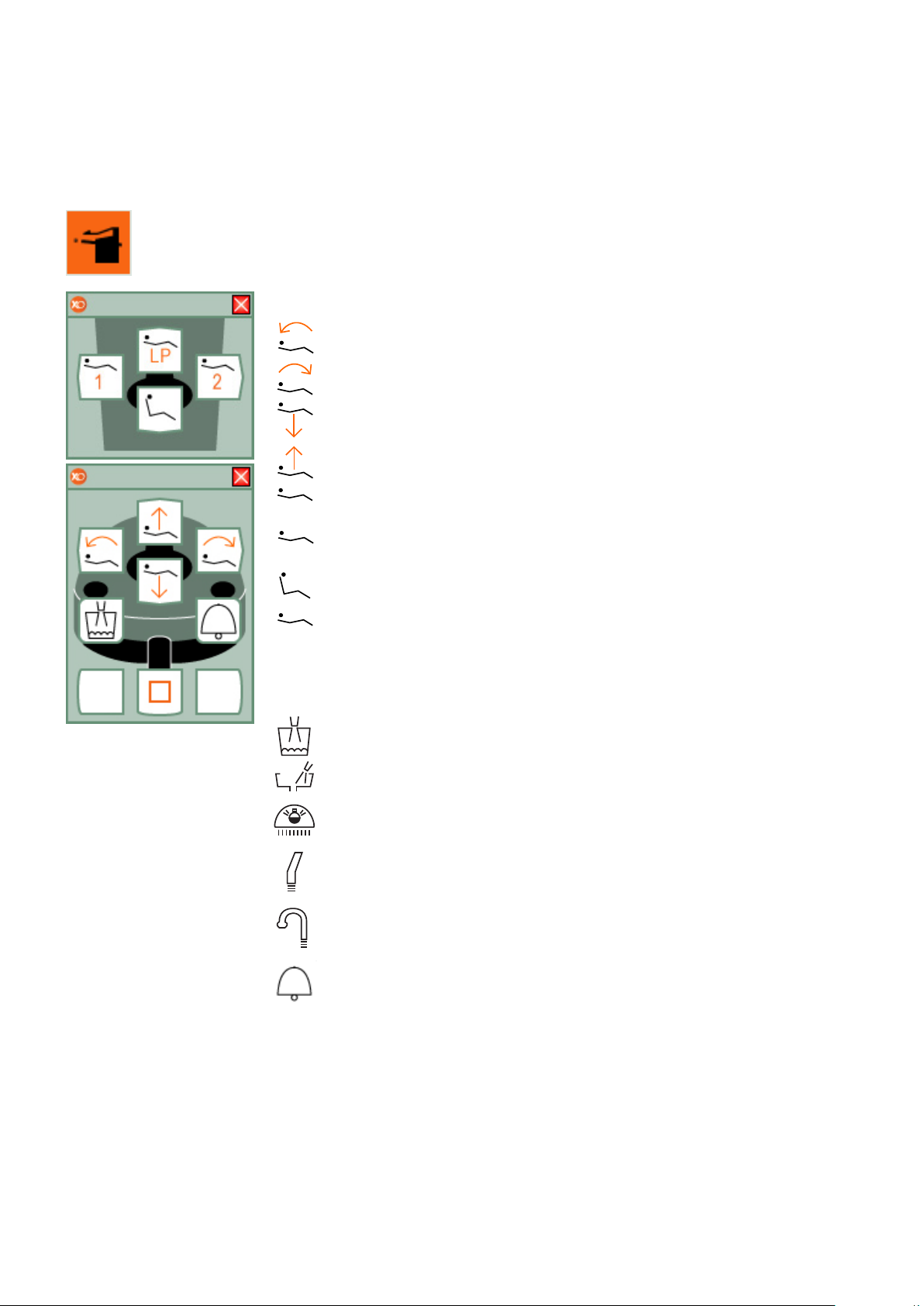
Unit & Chair cell selected
1
2
LP
All unit instruments rest
Chair functions
Move backrest down
Move backrest up
Move seat down
Move seat up
Go to position 1
Go to position 2
Unit & Chair cell operates the basic functions
of XO Unit.
The Unit & Chair cell is
only available when all
instruments are resting.
Go to exit position
Go to last position
Unit functions
Start/stop glasfiller
Flush bowl
Operating lamp on/off
Start/stop big suction
Start/stop small
suction
Assistance call
11
Page 12
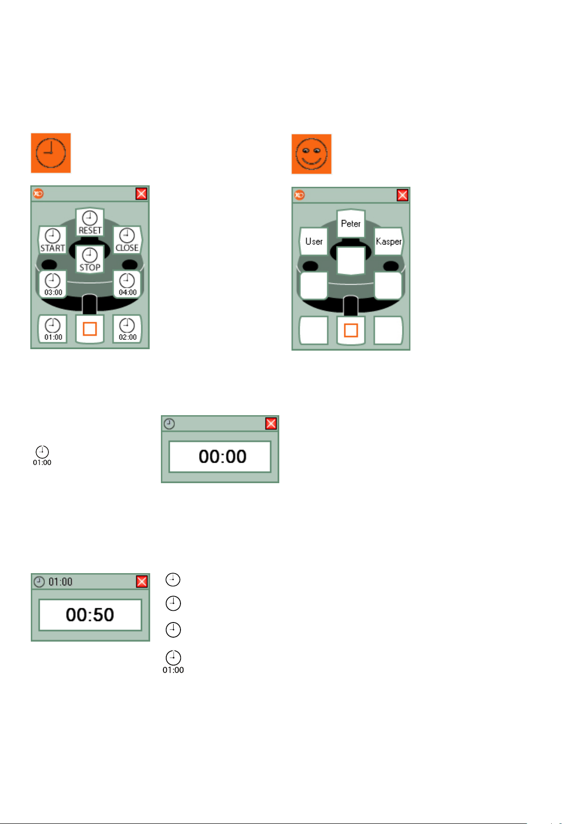
Timers & Stopwatch cell
START
STOP
RESET
User Management cell
selected
All unit instruments rest
mer window disappears
automatically after 10
seconds.
To adjust the timers
right click on the timer
cell on XO Bar and
choose / “Configuration”
/ “General configuration”.
Set each of the 4 timers
to the desired value.
The Timers & Stopwatch
cell allows you to control up to 4 configurable
timers and a
stopwatch.
Using the Timer
Timer
The timestamp (01:00)
on the icon shows the
countdown time in minutes and seconds.
Use Foot control to start
the countdown.
A timer window will appear.
When the countdown is
finished the unit will play
an alarm sound. The ti-
Using the Stopwatch
Use foot control to start
the stopwatch.
The stopwatch window
will appear.
You can stop and restart
a running stopwatch as
many times as desired.
Reset the stopwatch by
pressing the reset button.
selected
All unit instruments rest
The User Management
cell allows you to switch
between different XO
Smart Link users without using keyboard or
mouse.
XO Smart Link handles
up to 6 users, each with
a complete set of individual settings.
Changing users
Select the User Manager Plug-in. Look at XO
Screen User Guide and
activate the foot control
function corresponding
to the user you wish to
switch to.
Allow up to 10 seconds
for XO Smart Link to
reconfigure XO Unit.
Start stopwatch
Stop stopwatch
Reset stopwatch
Timer
12
Page 13
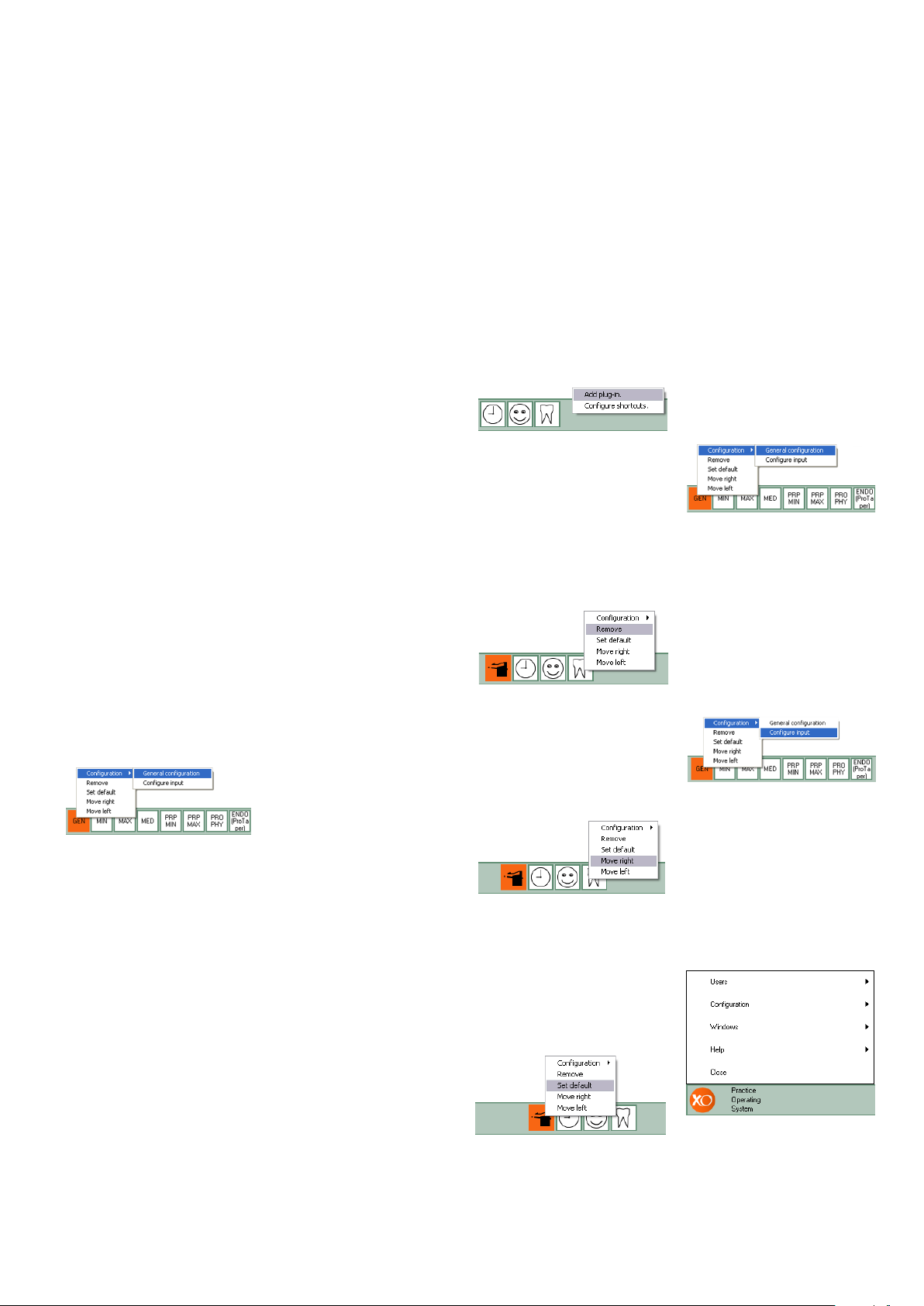
Configuration of XO Smart Link
Configuration of instrument activation curves
To change the activation
curve lift the instrument
forward and right click
on the program you
wish to change.
Select / “General configuration” / “Speeds,
torque & contra angle”
/ “Activation curve”.
Select activation curve
from the list.
On the page “Speeds,
torque & contra angle”
the maximum and minimum speed values can
be set.
The “Minimum speed”
value defines the start
speed of the instrument.
The “Maximum speed
levels” fields define the
3 maximum speeds.
Configuration of maximum torque of micro
motor and
XO OSSEO
To configure reduction
of the maximum torque
select: / “General configuration” / “Speeds,
torque & contra angle” /
“Torque reduction”.
The efficiency of different contra angles differs. Please consult the
table in the “more…”
label in “Rotating instruments tab” in the
configuration box.
Configuration of XO Bar
A core element in XO
Smart Link is XO Bar.
XO Bar facilitates the following functions.
Create plug-in:
Right click on an empty
spot on the XO Bar
(green area). Choose
“Add plug-in”.
Select the desired plugin from the list.
Remove plug-in:
Right click on the plug-in
to remove. Select “Remove” from the menu.
The default cell is
the cell first available
when XO Smart Link
is started. To set the
default cell right click
on the cell. Select “Set
default”.
Access the program
configuration mode:
Right click on the cell
to be changed. Select
“Configuration” / “General configuration”. The
configuration window
will now appear.
Access the input configuration mode:
Rearrange cells:
To rearrange the cells on
XO Bar right click on the
cell to move and select
“Move right” or Move
left”.
Set default program:
Right click on the cell
to be changed. Select
“Configuration” / “Configure input”. The input
configuration window
will now appear.
Access XO Menu:
To access XO Menu
click on XO logo on the
left side of XO Bar.
13
Page 14
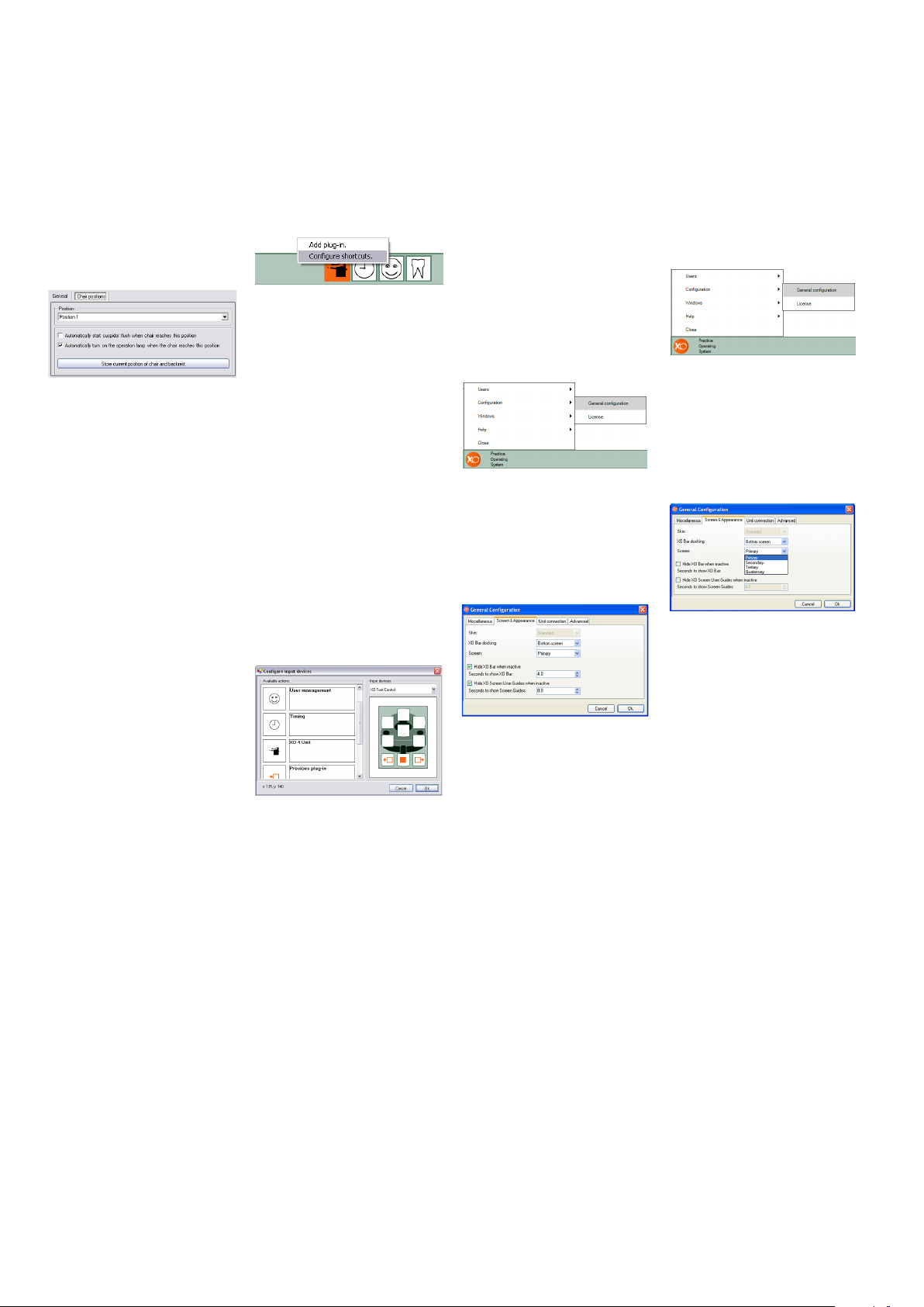
Programming chair
positions
Right click on the Unit
& Chair cell. From the
menu select “Configuration” / “General configuration”.
“XO Unit plug-in options” window appears.
Select “Chair positions”.
From the “positions”
drop-down menu select
the position to program.
Use foot control to move
the chair to the desired
position. Press “Store
current position of chair
and backrest”.
The programming is
now complete.
Configuration of
shortcuts
To create a shortcut use
the mouse to right click
on a free spot on XO
Bar.
Select “Configure
shortcuts”. The shortcut
configuration will now
appear.
From the list “Available actions” select the
action to which you wish
to create a shortcut.
Use the mouse to drag
the action symbol to the
desired location on foot
control palette on the
left.
Click “OK” to save and
exit.
Activating Auto Hide
In order to maximise
screen space for other
software application XO
Smart Link has a build
in “Auto Hide” function.
The “Auto Hide” function
automatically removes
(all or some) XO Smart
Link windows from the
computer screen when
XO Unit is not being
used.
To activate “Auto Hide”
Open XO Menu
Select / “Configuration”
/ “General Configuration”.
The General Configuration window will appear:
On the page “Screen &
Appearance” click “Hide
XO bar when inactive”.
Set desired idle time.
Multiple screens
For true multi screen
installations XO Smart
Link supports up to four
screens. To select the
screen to be used by XO
Smart Link:
Open XO Menu
Select / “Configuration”
/ “General Configuration”.
The General Configuration window will appear:
On the page “Screen
& Appearance” click
“Screen”. Select screen
to be used by XO Smart
Link.
NOTE ! The specific
functions of a multi
screen setup depends
on the software and
the hardware installed.
Functionality will vary
with different configurations.
14
Page 15

Errors
Installation
Please note:
1. In case of connection
problems check that
PC and XO Unit are
switched on and
that the RS 232 cable
connection is intact.
2. If the connection from
XO Unit to PC fails, the
unit will automatically
return to
XO Unit mode.
3. If correct operation of
the PC cannot be verified, please shutdown
the PC and run the unit
in XO Unit mode. Contact your PC supplier.
Warning:
XO Smart Link must be
installed by qualified
personnel. See installation guide for more
information about installing XO Smart Link.
Please be aware that
running processor
intensive applications,
in combination with
XO Smart Link, can
slow down the system
significantly and might
cause XO Smart Link
to malfunction. Always
make sure that your PC
hardware is scaled according to the applications installed.
4. If an error occurs
please check your
installation and then
restart XO Unit and XO
Smart Link. If the problem still occurs contact
your supplier. Do not run
XO Smart Link until the
problem is solved.
15
Page 16

Manufacturer
XO CARE A/S
Copenhagen
Denmark
2460
Ref.No.: YB-440
Ver. 3.50
Valid for XO SL ver. 4.4
XO is a registered trademark.
XO Smart Link is a trademark
belonging to XO CARE A/S.
Subject to change.
Usserød Mølle
Håndværkersvinget 6
DK 2970 Hørsholm
+45 70 20 55 11
xo-care.com
 Loading...