

XO®OSSEO
User Guide
YB-223
Version 3.00

XO CARE A/S
2 XO Osseo, User Guide YB-223 Version 3.00
CONTENTS
A. ILLUSTRATION AND COMPONENTS – XO OSSEO SYSTEM.................................................... 4
A.1 COMPONENT PARTS - STANDARD .................................................................................... 5
A.2 SUPPLEMENTARY ACCESSORIES......................................................................................5
B. GENERAL FEATURES .....................................................................................................................6
B.1 SPEED, TORQUE AND HANDPIECE ....................................................................................6
B.2 IRRIGATION...........................................................................................................................6
C. PREPARATION AND SET-UP...................................................................................................... 7
C.1 INSTALLATION......................................................................................................................7
C.2 SURGICAL PREPARATION................................................................................................... 7
C.2.1 HANDMOTOR AND CORD ..................................................................................................8
C.2.2 CONTRA-ANGLE HANDPIECE............................................................................................8
C.2.3 THE IRRIGATION TUBING SYSTEM ................................................................................... 8
D. IMPLANT SURGERY....................................................................................................................... 10
D.1 WORKING WITH FACTORY PRE-PROGRAMMED IMPLANT SYSTEM PARAMETERS ... 10
D.1.1 STARTING PROCEDURE................................................................................................... 10
D.1.2 PROGRAMME STEP - PRELIMINARY DRILLING .........................................................11
D.1.3 PROGRAMME STEP - FINAL DRILLING....................................................................... 11
D.1.4 PROGRAMME STEP - TAPPING (FORWARD) / SCREW-IN......................................... 12
D.1.5 PROGRAMME STEP - TAPPING (REVERSE) / SCREW-OUT....................................... 12
D.1.6 COVER SCREW .................................................................................................................13
D.2 INDIVIDUALIZING IMPLANT SYSTEM PARAMETERS....................................................... 13
E. GENERAL BONE SURGERY....................................................................................................... 15
E.1 STARTING PROCEDURE .................................................................................................. 15
E.2 SETTING SPEED ................................................................................................................. 16
E.3 SETTING TORQUE AND IRRIGATION ................................................................................ 16
F. CLEANING AND STERILIZATION ...............................................................................................17
F.1 CONTROL BOX AND FOOT CONTROL.............................................................................. 17
F.2 IRRIGATION TUBING ..........................................................................................................17
F.3 HANDPIECE.........................................................................................................................17
F.4 HANDMOTOR WITH CORD ................................................................................................ 18
F.5 SYSTEM ACCESS KEYS AND ADJUSTMENT PIN ............................................................ 18
G. ACCESSORIES - XO OSSEO SYSTEM ..................................................................................19
H.1 DISPOSAL.............................................................................................................................20
I. TROUBLESHOOTING ............................................................................................................... 21
J. TECHNICAL SPECIFICATIONS................................................................................................. 23
J.1 TYPE PLATE............................................................................................................................24
K. WARRANTY.............................................................................................................................24

XO CARE A/S
YB-223 Version 3.00 XO Osseo, User Guide 3
FOREWORD
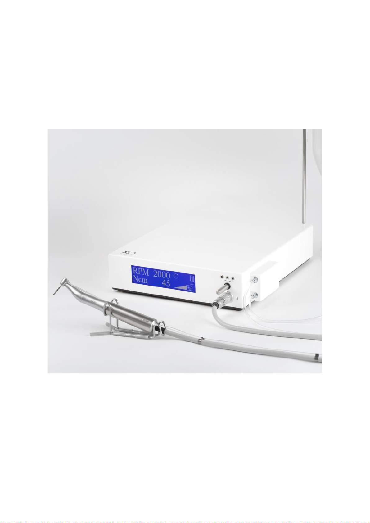
Your new XO OSSEO SYSTEM is a micro-motor unit designed for bone surgery in general and for
dental implantology in particular.
In your own interest we kindly ask and recommend that you take the time to carefully study this
manual in order to familiarize yourself with the XO OSSEO SYSTEM and its operation.
By doing so you will be able to take full advantage of the qualities of the XO OSSEO SYSTEM and
to operate without problems in actual practice.
XO CARE A/S
XO CARE A/S
4 XO Osseo, User Guide YB-223 Version 3.00
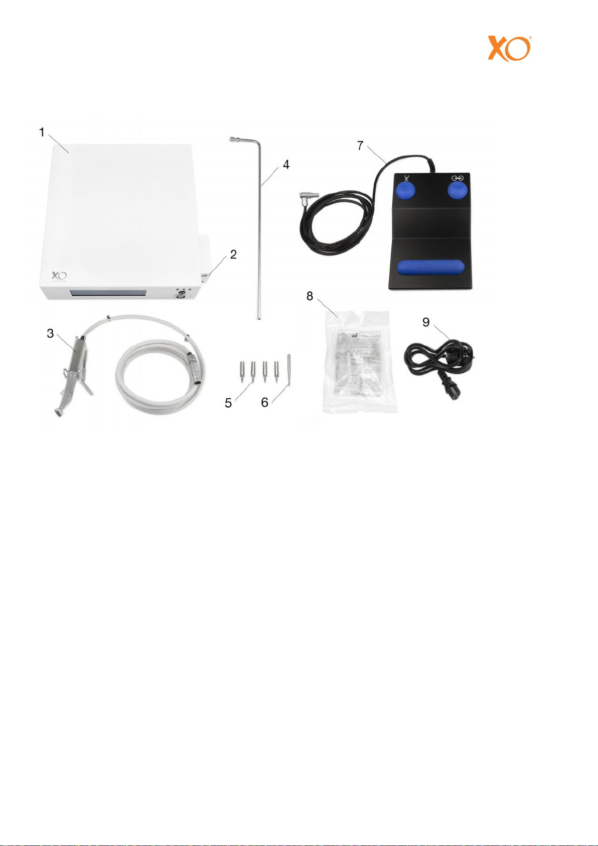
A. ILLUSTRATION AND COMPONENTS – XO OSSEO SYSTEM
1. Control box
2. Pump Cover
3. Handmotor with cord
(Contra-angle, 20:1 must be ordered
separately)
4. Bag hanger
5. System keys
6. Adjustment keys
7. Foot control
8. Tubing kit (one time use - supplied in pre-
sterilized package)
9. Power cord

XO CARE A/S
YB-223 Version 3.00 XO Osseo, User Guide 5
A.1 COMPONENT PARTS - STANDARD
As delivered, the XO OSSEO SYSTEM includes the following component parts:
Control box with display and integrated irrigation pump,
foot control,
bag hanger,
mains power cord,
surgery system access key "20:1”, speed range 15 – 2.000 rpm
surgery system access key "1:1”, speed range 300 - 40.000 rpm
adjustment pin,
handmotor with cord,
motor sealing plug,
five kits of pre-sterilized irrigation tubing,
five clips for tubing/cord hook-up
Prior to use, please check that these parts are present and are free of any damage.
A.2 SUPPLEMENTARY ACCESSORIES
The following extras are available, but are to be ordered separately:
Implant System Access Keys
Implant: Ref. No.:
Astra 260246
Bonefit 260242
Brånemark 260238
Screw Vent 260244
Steri-Oss 260250
Cover Screw
Display Language: Ref. No.:
English 260232
French 260234
German 260236
General Surgery System Access Keys
Gearing Ratio: Speed Range: Ref. No.:
2:1 150-20000 260222
10:1 30-4000 260224
15:1 20-2666 260263
100:1 3-400 260262
1:2 600-80000 260228
1:4 1200-160000 260230
Concerning accessories in general, please refer to Chapter G in this manual.

XO CARE A/S
6 XO Osseo, User Guide YB-223 Version 3.00
B. GENERAL FEATURES
The XO OSSEO SYSTEM is based on a system access key concept to allow access to factory
programmed sets of parameters i.e. speed, torque and irrigation flow rate. Two series of system
access keys are available:
1. Implant system access keys adapted specifically to placement of prevailing implant systems in
accordance with the respective implant manufacturer’s recommendations.
2. Surgery system access keys for bone surgery in general and designed to adapt or ”translate” the
output parameters - as shown on the display - of a handpiece in view of the specific gearing ratio
of the handpiece in question.
The factory-made parameter settings of each system access key can be manually altered and stored
to provide an individualized set of parameters.
B.1 SPEED, TORQUE AND HANDPIECE
The speed and torque actually coming out from a handpiece on the handmotor are determined
primarily by the gearing ratio of the handpiece.
All of the implant system access keys are based on a 20:1 reduction gearing and, accordingly, the
respective torque and speed values on the display will only be true, when that particular reduction
gearing is used.
For implantology we recommend the Micro-Méga 20 IMKB contra-angle because of its excellent
torque performance. With theXO OSSEO SYSTEM the 20 IMKB has an operation range of 15-2000
rpm and a maximum output torque of at least 45 Ncm.
As a result all necessary implant placement functions can be performed by one and the same
handpiece.
NOTE! The torque output may decrease to some extent over time due to handpiece wear.
B.2 IRRIGATION
Irrigation is highly recommended by most implant manufacturers.
The XO OSSEO SYSTEM, its irrigation tubing kit and the 20 IMKB handpiece allow four irrigation
options.
External irrigation only
Internal irrigation only
Combined external and internal irrigation
No irrigation (allows irrigation from other sources)
The flow rate capacity of the built-in pump unit is 20 ml to 65 ml per minute. The flow rate has been
factory-programmed to be about 35 ml per minute for each of the system access keys - but can
easily be altered and individualized.
In addition the irrigation can be independently switched ON and OFF by means of a separate foot
switch on the foot control.
XO CARE A/S
YB-223 Version 3.00 XO Osseo, User Guide 7
C. PREPARATION AND SET-UP
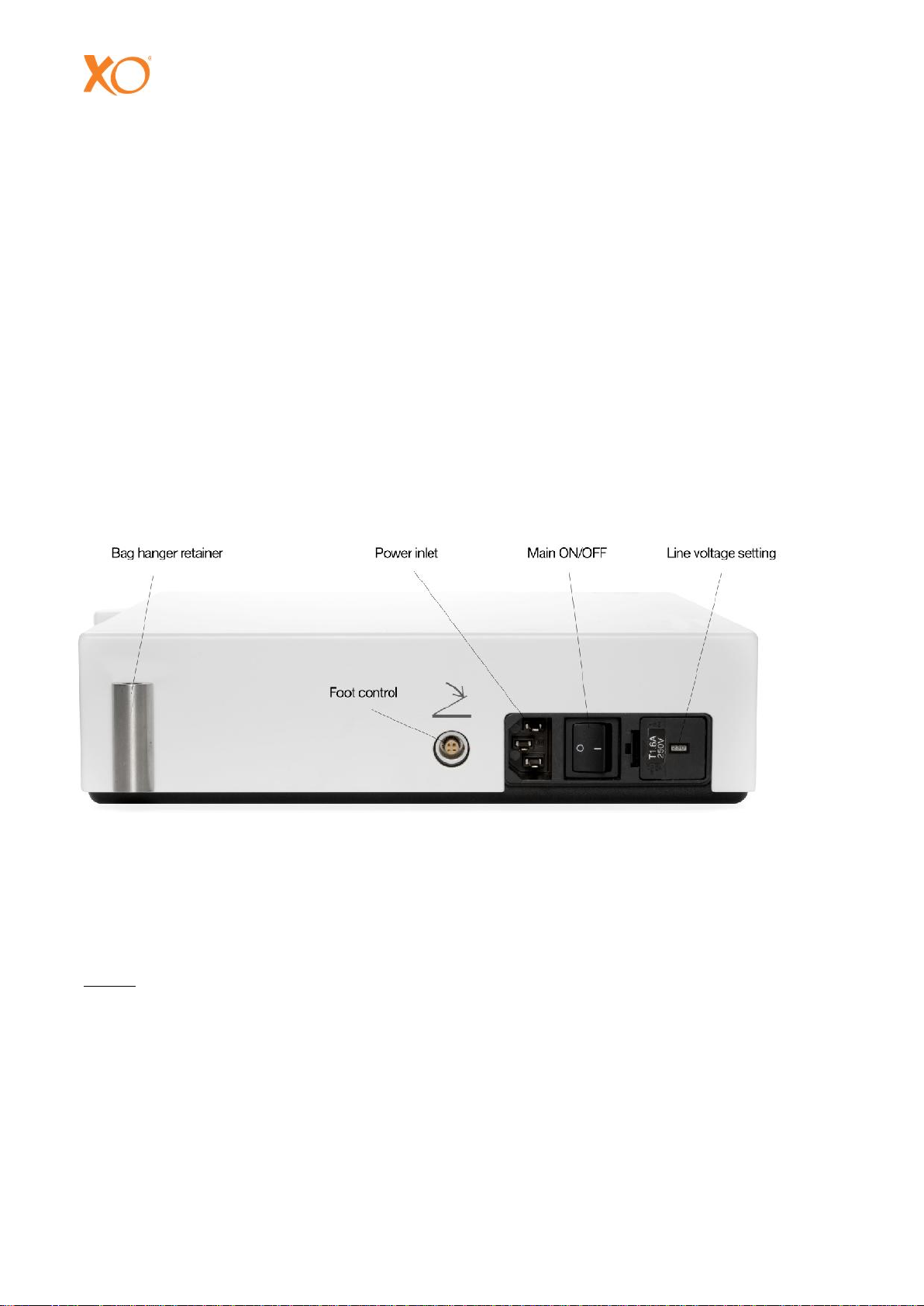
C.1 INSTALLATION
At first, make sure that the voltage setting of your unit is in accordance with your local supply line
voltage - see Fig. 1. Should this not be the case, contact your Dealer.
1. Connect the power cord with the power inlet on the rear of the control box (Fig. 1) and plug into
a wall socket with appropriate protective ground connection.
2. Connect the foot control by plugging its cable connector end into the socket on the rear of the
control box (Fig. 1).
3. Insert the bag hanger into its retainer on the rear of the control box (Fig. 1).
WARNING: To avoid the danger of electric shock, this device must be connected only to
grounded mains voltage.
Fig. 1
C.2 SURGICAL PREPARATION
The following instructions will prepare the XO OSSEO SYSTEM for surgery.
NOTE! Appropriate sterile handling procedures must be observed to ensure and maintain sterile
conditions.

XO CARE A/S
8 XO Osseo, User Guide YB-223 Version 3.00
C.2.1 HANDMOTOR AND CORD
1. Remove the sterilized handmotor and cord from the autoclave bag or wrapping just prior to
surgery. Regarding sterilization - see Chapter F.
2. Connect the handmotor cord with the matching socket on the front of the control box. Line up
the red dots on the connector and socket and push the connector firmly into the socket.
3. Place the handmotor on the sterile field.
4. Make sure that the instrument is not near the patient.
C.2.2 CONTRA-ANGLE HANDPIECE
1. Remove the sterilized handpiece from the autoclave bag just prior to surgery. Regarding
sterilization - see Chapter F.
2. Slide the handpiece firmly in place on the handmotor shaft and place the handmotor with
handpiece on the sterile field.
C.2.3 THE IRRIGATION TUBING SYSTEM
The XO OSSEO SYSTEM is delivered with irrigation tubing kits in pre-sterilized packages. The
tubings are for one time use only. Do not re-sterilize.
The tubing kit is designed for transferring irrigation liquid from a sterile source (sealed bag or bottle)
via the pump, and to the irrigation inlet on the contra-angle.
Each package includes:
- a main tubing and
- two outlet tubings (for alternative use)
The main tubing consists of three consecutive parts:
- an inlet part with bag cannula,
- a pump part between two plastic connectors,
- a transport part terminated by a male Luer lock connector
The two outlet tubings are:
1. A female Luer lock connector with one piece of tubing for connection with an irrigation inlet on
the contra-angle (either internal or external burr cooling).
2. A female Luer lock connector with two pieces of parallel tubings for connection with respective
irrigation inlets on the contra-angle (combined internal and external burr cooling).

XO CARE A/S
YB-223 Version 3.00 XO Osseo, User Guide 9
Mounting the irrigation tubing system
1. The non-sterile assistant removes the magnetically retained pump cover in order to expose the
pump rotor and the bracket with two (upper and lower) U-shaped cut-outs.
2. The non-sterile assistant opens the tubing package, and the sterile assistant takes out the main
tubing.
3. While held in position by the sterile assistant, the non-sterile assistant stretches the pump part
around the pump rotor and fits the two plastic connectors into the respective U-shaped cutouts.
See Illustration below.
Fig. 2
CAUTION: The pump tubing part must be correctly and
carefully stretched around the pump rotor with that plastic connector which
connects with the inlet part, placed in the upper U-cut-out.
4. The non-sterile assistant opens the separate sub-package including the two outlet tubings, and
the sterile assistant selectsthe desired outlet tubing necessary for the operation concerned (single
or combined burr cooling).
5. The sterile assistant removes the protective end cap on the male Luer lock connector on the
transport part and connects the desired outlet tubing therewith.
6. The sterile assistant connects the free end or ends of the outlet tubing with respective irrigation
inlets on the contra-angle for internal, external or combined burr cooling as the case may be.
7. The non-sterile assistant removes the protective end cap from the bag cannula, connects the
cannula with a sealed bag or bottle with sterile irrigant, and suspends the bag or bottle in the bag
hanger.
The irrigation system is now ready for operation.

XO CARE A/S
10 XO Osseo, User Guide YB-223 Version 3.00
CAUTION: The tubing kit package has been sterilized by radiation. Sterility cannot be relied upon:
1) if the package has been opened or damaged, and
2) after the expiration date stamped on the package.
D. IMPLANT SURGERY
The XO OSSEO SYSTEM is factory pre-programmed with sets of recommended system-specific
parameters for various implant systems. Access to such implant programmes only requires a
corresponding system access key which is available as an accessory - confer Chapter A.2 of this
manual.
Each implant programme includes four programme steps i.e. preliminary drilling, final drilling,
tapping (forward)/screw-in, tapping (reverse)/screw-out.
Each of these steps includes the following pre-programmed parameters: Speed (RPM), torque
(Ncm), direction of rotation (forward or reverse) and irrigation flow rate (H2O).
In addition, for implant systems requiring a cover screw, a special access key is available for lowtorque placement of such cover screws - see section D.1.6. of this Manual.
D.1 WORKING WITH FACTORY PRE-PROGRAMMED IMPLANT SYSTEM
PARAMETERS
The following instructions only relate to operation with system specific parameters as factory
programmed in accordance with respective implant manufacturer’s recommendations. It is possible,
however, to manually alter and individualize some of or all of the parameters - see Chapter D.2 of
this Manual.
NOTE! The factory pre-programmed parameters and the corresponding speed and torque
readings on the display have been defined and confirmed on the basis of a new MicroMéga 20 IMKB contra-angle which is strongly recommended for use with theXO OSSEO
SYSTEM.
Exact correspondence between displayed and actual torque values cannot be expected at all times
due to handpiece wear over time. In addition, substitution of a handpiece other than the 20 IMKB
may vary the speed and torque output to indeterminable levels.
D.1.1 STARTING PROCEDURE
1. Switch the unit ON by operating the main ON/OFF switch at the rear of the control box. The
display signals "Insert system key”.
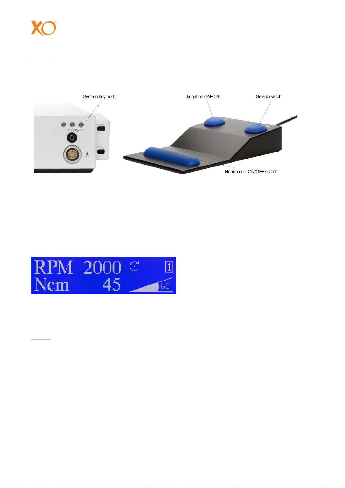
2. Insert the system access key corresponding to the implant system you are going to use, into the
system key port, see Fig. 3
3. The display will now show a system identification and a summary of pre-programmed values for
speed (RPM) and torque (Ncm) in each of the four programme steps.
XO CARE A/S
YB-223 Version 3.00 XO Osseo, User Guide 11
NOTE! A star () in front of the system identification is indicating that parameters have been
manually altered - see Chapter D.2 - relative to the standard factory programmed
parameter values.
Fig. 3 + 4
D.1.2 PROGRAMME STEP - PRELIMINARY DRILLING
Enter programme step by stepping once on the select switch on the foot control - see Fig. 4.
A typical example of a step display reading is shown in Fig. 5.
Fig. 5
Start the handmotor by stepping and holding the motor ON/OFF switch on the foot control - see Fig.
4.
NOTE! The irrigation pump starts about 1 second before the handmotor in order to ensure ample
irrigation. The pump and handmotor will stop as soon as the foot control switch is released.
The irrigation pump can be independently switched ON/OFF by operating the irrigation
ON/OFF switch on the foot control – see Fig. 4.
Programme step is useful for higher speed/smaller diameter drillings.
D.1.3 PROGRAMME STEP - FINAL DRILLING
Enter step by stepping once again on the select switch on the foot control (Fig. 4).
A typical example of a step display reading is shown in Fig. 6.
Speed = 2000 RPM
Torque = 45 Ncm
Direction of rotation = forward/clockwise
Irrigation = about 50 % of max

XO CARE A/S
12 XO Osseo, User Guide YB-223 Version 3.00
Fig. 6
Start the handmotor as before by means of the foot control.
Programme step is useful for lower speed/larger diameter drillings such as enlargement drillings
and final drillings.
D.1.4 PROGRAMME STEP - TAPPING (FORWARD) / SCREW-IN
Enter step by stepping on the select switch on the foot control (Fig. 4).
Fig. 7 is showing an example of a step display reading.
Fig. 7
Start the handmotor as before by means of the foot control.
Programme step is useful for low speed/high torque tapping for and screwing-in of
threaded implants.
D.1.5 PROGRAMME STEP - TAPPING (REVERSE) / SCREW-OUT
Enter step by stepping once again on the select switch on the foot control.
As shown in Fig. 8 the parameters are the same as in step except that the direction of
rotation has been changed to be in reverse (counter clockwise).
Fig. 8
As soon as the handmotor is started inreverse, there will be an alarmsignal and the direction symbol
on the display starts to flash.
Programme step is useful for returning the threading tap and for screwing out threaded implants.
Speed = 800 RPM
Torque = 45 Ncm
Direction of rotation = forward/clockwise
Irrigation = about 50 % of max
Speed = 15 RPM
Torque = 45 Ncm
Direction of rotation = forward
Irrigation = about 50 % of max

XO CARE A/S
YB-223 Version 3.00 XO Osseo, User Guide 13
Jumping forth and back between step (forward) and step (reverse) can be done by pressing the
select switch on the foot control.
Jumping from step and back to step can be done as follows.
a. For units manufactured before July 1997:
By taking out and re-inserting the system access key.
b. For units manufactured after July 1997:
By double-stepping the select switch on the foot control.
An alarm signal warns you about the jumping back to step .
D.1.6 COVER SCREW
For implant systems requiring placement of a cover screw, it is strongly recommended to use a
special system access key which is available as an accessory - see Chapter A.2 of this manual.
The cover screw system access key provides low speed and reduced torque for cover screw
placement.
1. Insert the system key into the system key port and note the factory programmed parameters on
the display i.e. speed = 25RPM, direction = forward and torque = 25Ncm. Irrigation is switched
OFF.
2. Start the handmotor by stepping the motor start switch on the foot control and hold down until
the handmotor is about to stall. The cover screw has now been tightened to the pre-set torque
of about 25 Ncm provided that the contra-angle is in good mechanical condition.
3. The direction of rotation can be reversed by stepping on the select switch on the foot control.
An alarm signal will sound as soon as the handmotor is started in reverse.
D.2 INDIVIDUALIZING IMPLANT SYSTEM PARAMETERS
The preceding section D.1 explained operation and use of system specific parameters as preprogrammed by the factory and as recommended by respective implant manufacturers.
It is, however, possible to manually alter or individualize parameter values.
1. Insert the implant system access key in question into thesystem key port - see Fig. 9 - and enter
the programme step in question by operating the select switch on the foot control - see Fig. 10.

XO CARE A/S
14 XO Osseo, User Guide YB-223 Version 3.00
Fig. 9 + 10
2. Enter the adjustment mode by clicking once into the central adjustment port - see Fig. 9 - by
means of the adjustment pin. The cursor (white background) on the display now indicates that
the speed (RPM) is open for adjustment.
3. If necessary, move the cursor to the desired parameter i.e. torque (Ncm) or irrigation flow rate
(H2O), by clicking the central adjustment port by means of the adjustment pin.
4. Adjust the parameter, thus opened, as desired. Increase by clicking the (+) port to the right and
decrease by clicking the (-) port to the left by means of the adjustment pin.
5. If desired, you may now move on to the next parameter by clicking the central adjustment port
and adjust as in point 4 above.
6. The parameter values thus manually altered must be stored and memorized by clicking the
central adjustment port until the cursor vanishes from the display.
NOTE! The handmotor cannot start until altered parameters have been stored in this way (cursor
vanished).
7. You may now move on to the next programme step of the system in question and adjust
parameter values as desired by repeating points 2-6 above.
The parameter values thus individualized and stored will be memorized by the XO OSSEO
SYSTEM, and the next time the system access key in question is plugged into the system key port,
the system summary on the display will show the parameters as altered. A star () in front of the
system identification will indicate that at least one parameter has been altered relative to the
factory programmed standard values.
Clicking once into the central adjustment port with the adjustment pin will return the system to its
standard parameter values.
The XO OSSEO SYSTEM is able to memorize parameter adjustments for up to five different
implant system access keys.

XO CARE A/S
YB-223 Version 3.00 XO Osseo, User Guide 15
If adjustments are being made to a sixth system key, the adjustment of the first altered of the five
preceding systems will be erased from the memory.
E. GENERAL BONE SURGERY
The XO OSSEO SYSTEM is of course also very useful for bone surgery in general - not least due to
its unique capability of low speed/high torque operation.
Special surgery access keys are available to adapt the display of the XO OSSEO SYSTEM to
handpieces and contra-angles with various gear ratios.
The XO OSSEO SYSTEM includes, as delivered, two such surgery keys i.e. 20:1 and 1:1. See also
chapter A.2 of this manual.
The parameters speed (RPM), torque (Torque %) and irrigation flow rate (H2O) can be adjusted
individually.
NOTE! The torque setting is displayed in percent of the maximum torque output for the
handpiece in question.
E.1 STARTING PROCEDURE
1. Switch the unit ON by operating the main ON/OFF switch at the rear of the control box. The
display signals "Insert system key”.
2. Insert the surgery access key corresponding to the gear ratio of the handpiece you are going to
use, into the system key port – see Fig. 11.
Fig. 11 + 12
3. The display will now show an identification. An example (20:1) is shown in Fig. 12. The example
tells you that theXO OSSEO SYSTEMis now ready for operation with a handpiece with reduction
gear ratio 20:1 and that the speed (RPM) of a tool in the handpiece can be adjusted within the
range of 15-2000 rpm.

XO CARE A/S
16 XO Osseo, User Guide YB-223 Version 3.00
4. Enter the programme by stepping on the select switch on the foot control - see Fig. 13. The
display will now show the factory-made parameter settings. The example (20:1) shown in Fig. 14
tells you that output speed = 800 RPM, output torque = 100 % of max, and irrigation = about
50% of max.
These parameter settings will be in force, if you start the handmotor at this stage.
Fig. 13 + 14
The parameter settings can be altered at any time, and the irrigation can be independently switched
ON and OFF by operating the irrigation switch on the foot control.
E.2 SETTING SPEED
The speed setting can be altered exclusively by operating switches on the foot control.
1. Enter the adjustment mode by stepping once on the select switch on the foot control. A cursor
(white background) on the display and a plus sign (+) now indicate that the speed is open for
increasing.
2. If you wish to decrease the speed setting, step once again on the select switch and a minus sign
(-) indicates that the speed is open for decreasing.
3. Increasing (point 1) as well as decreasing (point 2) the speed setting can be made by stepping
on the motor ON/OFF switch on the foot control. Store your speed settings by operating the
select switch on the foot control until the cursor vanishes from the display.
NOTE: The handmotor cannot start as long as the cursor is present on the display.
E.3 SETTING TORQUE AND IRRIGATION
The remaining parameters i.e. torque and irrigation flow rate (H2O) can be individually adjusted by
means of the adjustment pin and parameter adjustment ports - Fig. 15.

XO CARE A/S
YB-223 Version 3.00 XO Osseo, User Guide 17
Fig. 15
1. Enter the adjustment mode by clicking once into the central adjustment port with the adjustment
pin. The cursor now indicates that the torque is open for setting.
2. Adjust as desired. Increase by clicking the (+) port to the right and decrease by clicking the (-)
port to the left.
3. Open the irrigation flow rate (H2O) for setting by clicking once again into the central adjustment
port and adjust as in point 2 above.
4. Store your settings either by clicking the central port until the cursor vanishes or by stepping
once on the motor ON/OFF switch on the foot control.
You are now ready to operate with your own parameter settings. Start the handmotor by stepping
and holding the motor ON/OFF switch on the foot control.
F. CLEANING AND STERILIZATION
F.1 CONTROL BOX AND FOOT CONTROL
Clean and disinfect the control box, bag hanger and foot control by wiping all surfaces thoroughly
with an alcohol sponge or a micro-biologically tested surface disinfectant.
The control box and foot control cannot be autoclaved.
F.2 IRRIGATION TUBING
The irrigation tubing kit is for one time use only. Discard after use. Cannot be re-sterilized.
F.3 HANDPIECE

XO CARE A/S
18 XO Osseo, User Guide YB-223 Version 3.00
Handpieces and contra-angels must be cleaned, maintained and sterilized strictly in accordance
with the handpiece manufacturer’s specifications and recommendations. Failure to do so may result
in reduced torque performance and shortened lifetime of the handpiece.
F.4 HANDMOTOR WITH CORD
The handmotor is supplied with a sealing plug which has an O-ring at the end. Prior to autoclaving,
push this end of the sealing plug into the open center of the handmotor shaft.
CAUTION: Failure to autoclave the handmotor with the sealing plug in place may cause
damages to the handmotor.
CAUTION: Do not lubricate through the open front end of the handmotor.
Double wrapping is recommended.
Sterilize only by steam autoclaving at a max. temperature of 135°C (275°F) and with a hold time of
at least 4 minutes.
Higher autoclave temperatures (flash autoclaving) and other sterilization methods may damage the
equipment beyond repair.
Do not leave the handmotor and cord over-night in the autoclave.
Carrier for handmotor can be autoclaved at a max. temperature of 135°C (275°F) and with a hold
time of at least 4 minutes.
F.5 SYSTEM ACCESS KEYS AND ADJUSTMENT PIN
The system access keys and the adjustment pin can be steam autoclaved together with the
handmotor and cord i.e. with the same autoclave temperature of max. 135°C (250°F) and hold time
of 4 minutes.

XO CARE A/S
YB-223 Version 3.00 XO Osseo, User Guide 19
G. ACCESSORIES - XO OSSEO SYSTEM
Part No. Specification
260246 Implant system access key ”Astra”
260242 Implant system access key ”Bonefit”
260238 Implant system access key ”Brånemark”
260244 Implant system access key ”Screw Vent”
260250 Implant system access key ”Steri-Oss”
260232 System access key ”Cover Screw” (display text in English)
260234 System access key ”Vis de Couverture” (display text in French)
260236 System access key ”Okklusal Schraube” (display text in German)
260230 Surgery system access key ”1:4”, speed range 1200-160000 rpm
260228 Surgery system access key ”1:2”, speed range 600-80000 rpm
260220 Surgery system access key ”1:1”, speed range 300-40000 rpm
260222 Surgery system access key ”2:1”, speed range 150-20000 rpm
260224 Surgery system access key ”10:1”, speed range 30-4000 rpm
260263 Surgery system access key ”15:1”, speed range 20-2666 rpm
260227 Surgery system access key ”20:1”, speed range 15-2000 rpm
260262 Surgery system access key ”100:1”, speed range 3-400 rpm
260358 Handmotor complete with standard cord, 2.5 m hand motor sealing plug
160095 Motor sealing plug
260217 Foot Control complete with cord and connector
360208 Programme adjustment pin
260210 Bag hanger
360210 Pre-sterilized, disposable surgical tubing kit
360213 Five cord clips
WARNING: Only use XO CARE approved products for this device.
WARNING: It is prohibited to make changes to the device’s construction.

XO CARE A/S
20 XO Osseo, User Guide YB-223 Version 3.00
H. MAINTENANCE AND SAFETY
The following items should be observed at all times:
The XO OSSEO SYSTEM and its accessories must not be taken into use, if signs of operational,
electrical or mechanical defects are found.
The XO OSSEO SYSTEM must be installed and operated in accordance with this Manual.
The control box and foot control must not be exposed to excessively high or low temperatures
and extreme moisture.
The XO OSSEO SYSTEM is certified under the safety requirements of EN 60601-1 (IEC 601-1)
and EN 60601-1-2 class B.
Technical changes including repairs, adjustments or calibrations and modifications may only be
made by XO CARE A/S or specialists approved by XO CARE A/S.
The XO OSSEO SYSTEM should be submitted to your dealer or to XO CARE A/S for general
service check-up at least every two years.
WARNING: To avoid the danger of electric shock, this device must be connected only to
grounded mains voltage.
WARNING: Only use XO Care approved products for this device.
WARNING: It is prohibited to make changes to the device’s construction.
H.1 DISPOSAL
Spare parts, which are not to be used anymore, should be cleaned before they are disposed of in
accordance with the applicable rules for electric scrap.

XO CARE A/S
YB-223 Version 3.00 XO Osseo, User Guide 21
I. TROUBLESHOOTING
In case of difficulties or malfunction please check the following items.
The display is not illuminated:
1. Check the main power connection. The power cord may not be plugged in properly.
2. Check the fuses.
The display signals "Unknown system key":
1. The system access key has not been plugged in properly.
2. The system access key is defective. Replace.
The handpiece does not operate:
1. Determine if the handmotor is running. Remove the handpiece and start the motor at a high
speed. You should be able to hear the motor running. If not, go on to next section.
2. If the motor is running, re-attach the handpiece and check that that it is fully and properly
seated on the handmotor. The end of the handpiece must be flush with the end of the
handmotor.
3. Check that the drill is properly seated in the chuck of the handpiece head.
The handmotor does not operate:
1. Make sure that the motor cord connector is pushed fully and firmly into its socket on the front
of the control box.
2. Make sure that the foot control is connected properly with the control box.
3. Manually altered parameters may not be properly stored in the memory. Confer Chapters D2
(point 6), E2 (point 4) and E3 (point 4) of this manual.
No irrigation flow:
1. Is the pump rotor running? If not, step once on the irrigation ON/OFF switch on the foot control.
2. If the pump rotor is running, disconnect the irrigation tubing end from the handpiece and start
the pump. Does liquid come out from the tubing end? If so, check the handpiece for clogging.
3. If no liquid comes out, check the entire tubing system - in particular:
a) Is the pump part looped and stretched correctly around the pump rotor? See chapter
C.2.3 (Fig. 2) of this manual.
b) Is the bag cannula pushed through the seal on the irrigation bag?
c) In case of a glass bottle - is it possible to admit air into the bottle during its emptying?

XO CARE A/S
22 XO Osseo, User Guide YB-223 Version 3.00
Irrigation flow leaks after pump stops:
1. The pump part of the tubing is not sufficiently stretched around the pump rotor.
CAUTION: The items above represent the problems that can be overcome without
sending the unit for repair.
Do not attempt to repair or service the unit your- self.
Contact XO CARE A/S or your Dealer for additional assistance and
arrangements for repair, if necessary.

XO CARE A/S
YB-223 Version 3.00 XO Osseo, User Guide 23
J. TECHNICAL SPECIFICATIONS
Speed range: 15-2000 rpm with 20:1 reduction handpiece.
Max. driving torque: At least 45 Ncm with MM 20 IMKB contra-angle.
Irrigation pump: 20-65 ml/min., adjustable
Classification: Class 1, Type B (EN 60601-1 and EN 60601-1-2 class B
BF applied equipment.
Mains voltage: 115/230V, 50-60 Hz
Mains connection: 1-phase with protective ground
Max. power consumption: 380 VA
Fuses: 2 pcs. T 3.15A (115V)
2 pcs. T 1.6AL (230VAC)
Replacement of fuse: Fuse carrier is removed and fuse is replaced.
Surroundings operational: +10 to +35 degrees Celsius.
30-70% air humidity. 70-106 kPa.
Surroundings -40 til +70 degrees Celsius.
Transport, storage: 10-98% air humidity. 50-96 kPa.
Manufacturer: XO CARE A/S
Usserød Mølle,
Håndværkersvinget 6
DK-2970 Hørsholm
Denmark
Tel: + 45 70 20 55 11
info@xo-care.com
www.xo-care.com

XO CARE A/S
24 XO Osseo, User Guide YB-223 Version 3.00
J.1 TYPE PLATE
The type plate is located on the bottom of the control box and contains the following information:
K. WARRANTY
For the XO OSSEO SYSTEM as defined in Chapter A.1 of this manual, XO CARE A/S grants a
warranty of 12 months as from the date of the Contract of Sale and in accordance with terms and
conditions defined on the Guarantee Card going with each unit.
Defects proven to be caused by failure of materials, construction or manufacturing will be repaired
free of charge. Any further liability is explicitly declined.
The warranty does not apply to normal wear or to damage resulting from accident, abnormal use,
misuse, abuse or neglect.
Guarantee repairs or replacements will only be carried out upon receipt of the defect unit together
with its Guarantee Card.
Responsibility as to the safety, reliability and performance of the XO OSSEO SYSTEM will not be
accepted by XO CARE A/S:
a) If the equipment has not been used under normal conditions for its intended purposes
and in strict accordance with this manual and/or
b) if any technical changes including repairs, adjustments, calibrations and reconstructions
have been made by anyone other than XO CARE A/S or specialists approved by XO
CARE A/S.
The purchaser assumes all risks and liabilities resulting from the use of the XO OSSEO SYSTEM,
whether used separately or in combination with other products not manufactured by XO CARE A/S.
XO CARE A/S continually strives to improve its products and therefor reserves the right to improve,
modify or discontinue products at any time, and to change the specifications without notice and
without incurring obligations.

XO is a registered trademark.
Printing errors, if any, are subject to reservations,
and XO CARE A/S reserves the right at any time to
alter specifications without further notice.
© 2015 All rights reserved XO CARE
 Loading...