

XOC24SMUA
XOC30SMUA
XOC36S
XOC30S
NEED HELP?
Call our ventilation experts toll free al 800-966-8300
AVEZ-VOUS BESOIN D’AIDE ?
Contactez nos experts au numéro gratuit 800-966-8300
¿NECESITA AYUDA?
Póngase en contacto con nuestros expertos a través del número gratis 800-966-8300
USA
F
E
RANGE HOOD - User instructions
HOTTE DE CUISINE - Notice d’utilisation
CAMPANA EXTRACTORA - Manual de utilización

XO Hood Warranty
Proof of original purchase date and invoice is needed to obtain
service under warranty.
What is covered
What is not covered
Limited 2 Year Warranty.
For 2 years from the original date of purchase, we will provide,
free of charge, parts and service labor in your home to repair or
replace any part of the hood that fails because of a manufacturing defect.
The warranty is extended to the original purchaser for products
purchased for ordinary home use in North America.
Should you require service for your XO product call a product
service specialist at 800.966.8300
Improper Installation.
Service trips to the home to teach you how to use the product.
Resetting circuit breakers.
Damage caused after delivery.
EXPECT MORE FROM XO
When buying any XO appliance
you can be condent
you have purchased a high quality,
innovative, and stylish product,
from a company who cares about you
ENGLISH
IMPORTANT SAFETY INSTRUCTIONS
FOR RESIDENTIAL USE ONLY
USA
READ AND SAVE THESE INSTRUCTIONS
PLEASE READ ENTIRE INSTRUCTIONS BEFORE PROCEEDING.
IMPORTANT: Save these Instructions for the Local Electrical Inspectors use.
INSTALLER: Please leave these Instructions with this unit for the owner.
OWNER: Please retain these instructions for future reference.
Take care when using cleaning agents or detergents.
Suitable for use in household cooking area.
WARNING - To reduce the risk of re or electric shock, do not use this fan with any
Solid-State Speed Control Device.
CAUTION - To reduce risk of re and to properly exhaust air, be sure to duct air out-
side – Do not vent exhaust air into spaces within walls or ceilings or into attics, crawl
spaces, or garages.
CAUTION - For general ventilating use only. Do not use to exhaust hazardous or ex-
plosive materials and vapors.
CAUTION - To avoid motor bearing damage and noisy and/or unbalanced impellers,
keep drywall spray, construction dust, etc. o power unit.
CAUTION - Please read specication label on product for further information and
requirements.
WARNING – TO REDUCE THE RISK OF FIRE, ELECTRIC SHOCK, OR INJURY TO PERSONS,
OBSERVE THE FOLLOWING:
A. Use this unit only in the manner intended by the manufacturer. If you have questions,
contact the manufacturer.
B. Before servicing or cleaning unit, switch power o at service panel and lock the ser-
vice disconnecting means to prevent power from being switched on accidentally.
When the service disconnecting means cannot be locked, securely fasten a prominent warning device, such as a tag, to the service panel.
WARNING - TO REDUCE THE RISK OF A RANGE TOP GREASE FIRE:
A. Never leave surface units unattended at high settings. Boilovers cause smoking and
greasy spillovers that may ignite. Heat oils slowly on low or medium settings.
B. Always turn hood ON when cooking at high heat or when ambeing foods ( i.e.
- 3 -

Crepes Suzette, Cherries Jubilee, Peppercorn Beef Flambè ).
C. Clean ventilating fans frequently. Grease should not be allowed to accumulate on
fan or lter.
D. Use proper pan size. Always use cookware appropriate for the size of the surface
element.
E. Keep fan, lters and grease laden surface clean.
F. Use high range setting on range only when necessary.Heat oil slowly on low to me-
dium setting.
G. Don’ t leave range unattended when cooking.
H. Always use cookware and utensils appropriate for the type and amount o food be-
ing prepared.
WARNING – TO REDUCE THE RISK OF INJURY TO PERSONS IN THE EVENT OF A RANGE
TOP GREASE FIRE, OBSERVE THE FOLLOWINGa:
A. SMOTHER FLAMES with a close-tting lid, cookie sheet, or metal tray, then turn o
the burner. BE CAREFUL TO PREVENT BURNS. If the ames do not go out immediately,
EVACUATE AND CALL THE FIRE DEPARTMENT.
B. NEVER PICK UP A FLAMING PAN – You may be burned.
C. DO NOT USE WATER, including wet dishcloths or towels – a violent steam explosion
will result.
D. Use an extinguisher ONLY if:
1. You know you have a Class ABC extinguisher, and you already know how to operate it.
2. The re is small and contained in the area where it started.
3. The re department is being called.
4. You can ght the re with your back to an exit.
a
Based on “kitchen resafety tips” published by NFPA
Proper maintenance of the Range Hood will assure proper performance of the
unit.
INSTALLATION INSTRUCTIONS
WARNING – TO REDUCE THE RISK OF FIRE, ELECTRIC SHOCK, OR INJURY TO PERSONS,
OBSERVE THE FOLLOWING:
A. Installation work and electrical wiring must be done by qualied person(s) in accord-
ance with all applicable codes and standards, including re-rated construction.
B. Sucient air is needed for proper combustion and exhausting of gases through the
ue (chimney) of fuel burning equipment to prevent back drafting. Follow the heating equipment manufacturer’s guideline and safety standards such as those published by the National Fire Protection Association (NFPA), and the American Society
for Heating, Refrigeration and Air Conditioning Engineers (ASHRAE), and the local
code authorities.
C. When cutting or drilling into wall or ceiling, do not damage electrical wiring and
other hidden utilities.
D. Ducted fans must always be vented to the outdoors.
- 4 -

E. This unit must be grounded.
WARNING - TO REDUCE THE RISK OF FIRE, USE ONLY METAL DUCTWORK.
WARNING - UNDER CERTAIN CIRCUMSTANCES DOMESTIC APPLIANCES MAY BE DAN-
GEROUS.
A. Do not check lters with hood working.
B. Do not touch the lamps after a prolonged use of the appliance.
C. No food must be cooked ambè underneath the hood.
D. The use of an unprotected ame is dangerous for the lters and could cause res.
E. Watch constantly the fried food in order to avoid the cooking oil ares up.
F. Before performing any mainteinance operation, disconnect the hood from the elec-
trical service.
The manufacturers will not to accept any responsability for eventual damages, be-
cause of failure to observe the above instructions.
- 5 -
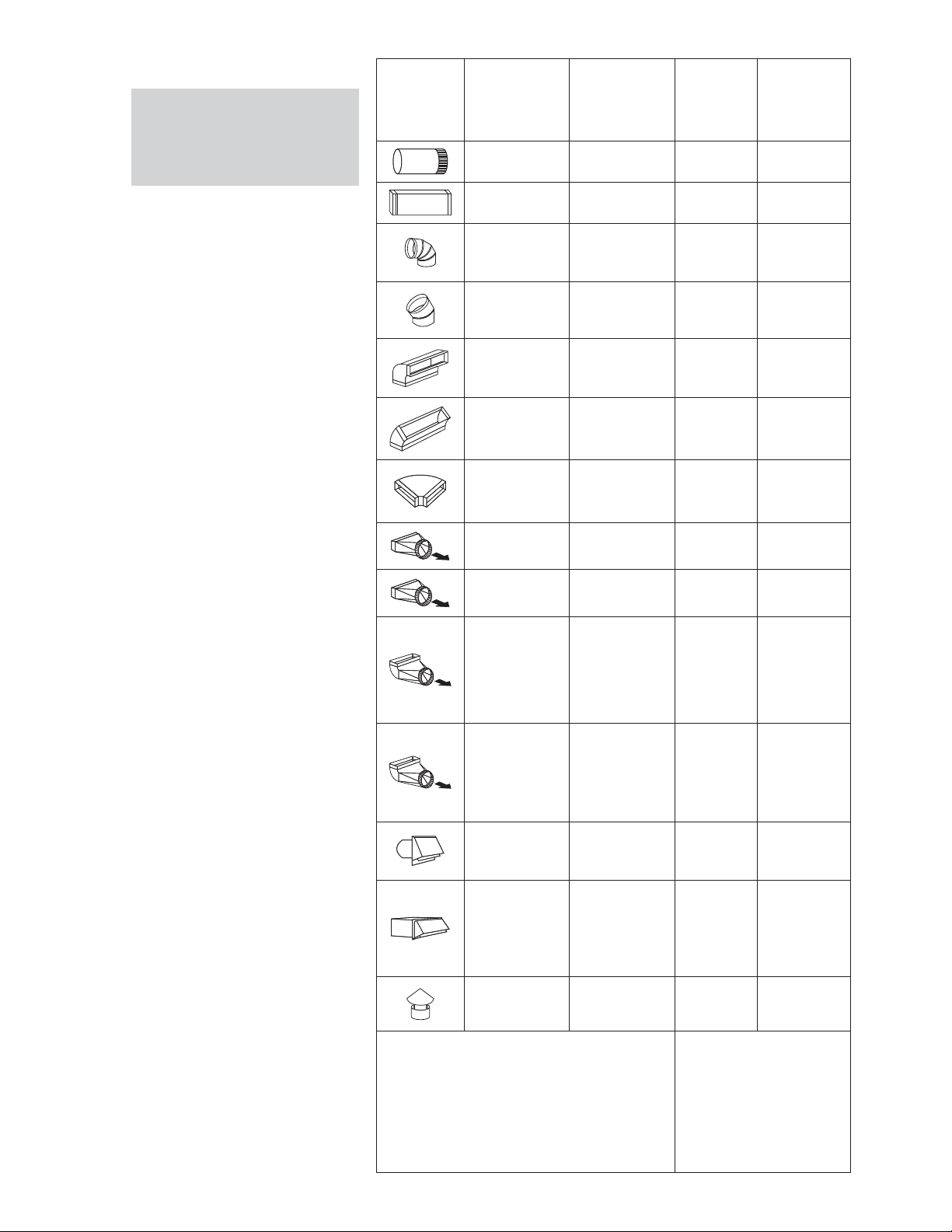
DUCT FITTINGS:
This Hood Must Use an
6" Round Duct. It Can
Transition to 3-1/4" x
10" or 3-1/4" x 12" Duct.
Use this chart to compute maximum permissible
lengths for duct runs to
outdoors.
Duct
Piece:
Equivalent
Dimensions:
Round, straight
3-1/4" x 10"
straight
90° elbow 12 ft.
Number
Length*:
1 ft. (per foot
lenhgth)
1 ft. (per foot
lenhgth)
Quantity
Used:
Total
Equivalent
Length:
NOTE: Do not exceed maxi-
Installation Preparation
mum permissible equivalent
lengths!
Maximum duct length:
100 feet for range ho-
ods.
Flexible ducting:
If flexible metal ducting
is used, all the equivalent
feet values in the table
should be doubled. The
flexible metal duct should
be straight and smooth
and extended as much as
possible.
DO NOT use flexible plastic
ducting.
NOTE: Any home ventilation
system, such as a ventilation
hood, may interrupt the
proper flow of combustion
air and exhaust required
by fireplaces, gas furnaces,
gas water heaters and other
naturally vented systems. To
minimize the chance of interruption of such naturally
vented systems, follow the
heating equipment manufacturer’s guidelines and
safety standards such as
those published by NFPA.
45° elbow 7 ft.
3-1/4" x 10"
3-1/4" x 12"
90° elbow
3-1/4" x 10"
3-1/4" x 12"
45° elbow
3-1/4" x 10"
3-1/4" x 12"
90° elbow
6" round to
rectangular
Rectangular to
8" round
3-1/4" x 10"
3-1/4" x 12"
6" round to
rectangular
transition 90°
elbow
3-1/4" x 10"
3-1/4" x 12"
Rectangular to
6" transition
90° elbow
Round wall
cap with
dramper
3-1/4" x 10"
3-1/4" x 12"
Rectangular
wall cap with
dramper
Round roof
cap
14 ft.
10 ft.
8 ft.
6 ft.
33 ft.
24 ft.
2 ft.
2 ft.
4 ft.
4 ft.
4 ft.
4 ft.
24 ft.
24 ft.
18 ft.
33 ft.
*Actual length of straight duct plus duct
fitting equivalent. Equivalent length of duct
pieces reflect requirements for good venting
performance with any ventilation hood.
- 6 -
Total Duct Run =
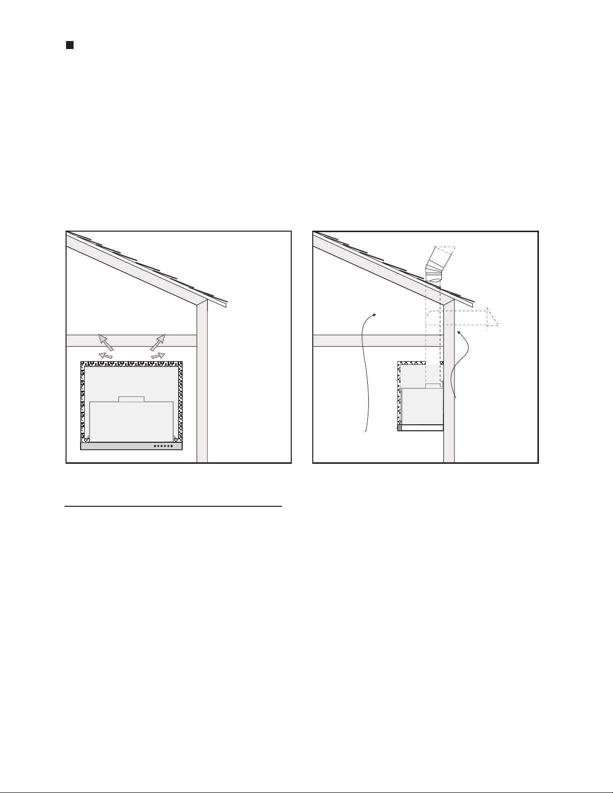
WARNING FIRE HAZARD
NEVER exhaust air or terminate duct work into spaces between walls, crawl spaces,
ceiling, attics or garages.
All exhaust must be ducted to the outside, unless using the recirculating option.
Use single wall rigid Metal ductwork only.
Fasten all connections with sheet metal screws and tape all joints w/ certied Silver
Tape or Duct Tape.
Installation - Ducting Options
INSTALL THE DUCTWORK:
NOTE: To reduce the risk of re, use only metal ductwork.
1. Decide where the ductwork will run between the hood and the outside.
2. A straight, short duct run will allow the hood to perform most eciently.
3. Long duct runs, elbows, and transitions will reduce the performance of the
hood. Use as few of them as possible.
4. Install a roof or wall cap. Connect 6" round metal ductwork to cap and work
back towards hood location. Use duct tape to seal the joints between ductwork
sections.
- 7 -
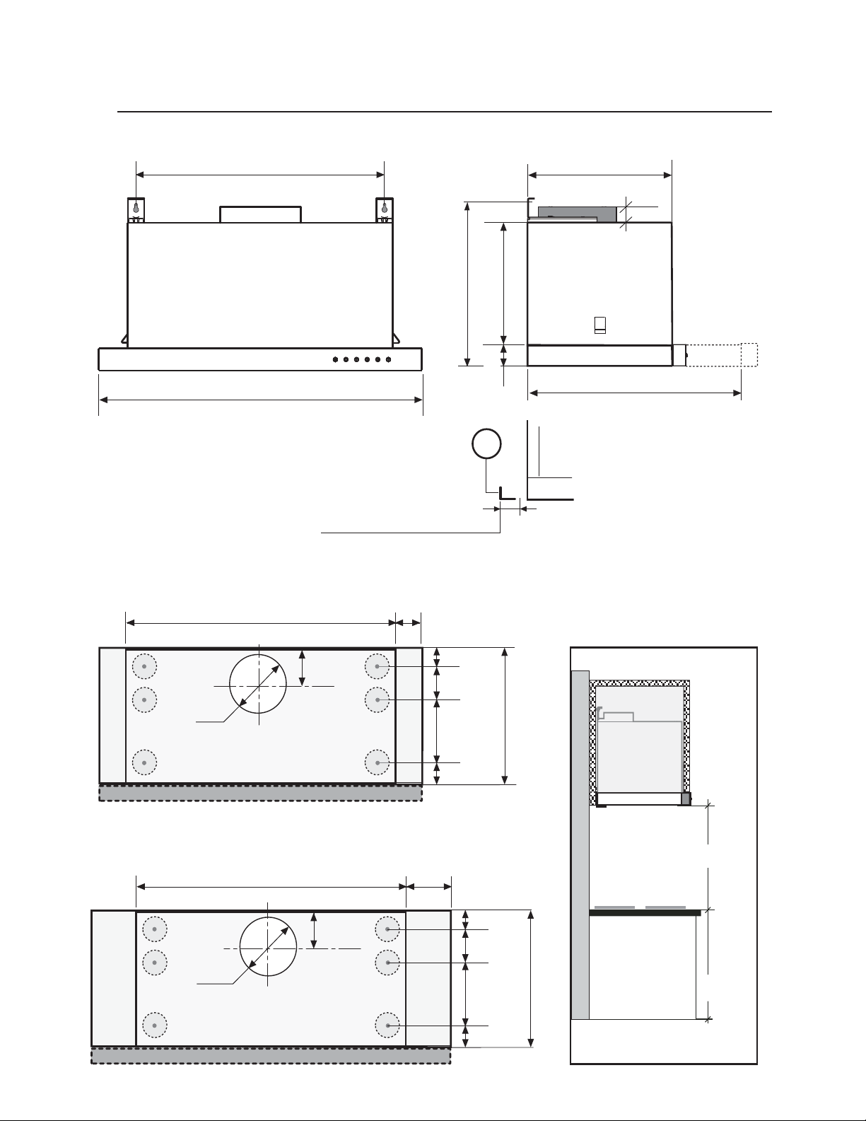
PRODUCT DIMENSIONS AND CLEARANCE
XOC24SMUA - XOC30SMUA - XOC36S - XOC30S:
Front of hood
18-5/8" (24" - 30")
30-7/16" (36")
Side of hood
11-1/16"
1-3/16"
Hood Specications
9"
12-1/8"
23-9/16" (24") - 29-15/16" (30") - 35-3/8" (36")
1-9/16"
L
min 0 - 0/16" - max 1 - 4/16"
min 0 - 0/16" - max 1 - /4"
Top of hood Mounting height and
clearance:
19-11/16" (24")
1-15/16" (24"-36")
16-15/16"
31-1/2" (36")
Ø 6"
Ø 6"
3-13/16"
19-11/16" (30")
3-13/16"
1-11/16"
2-9/16"
5-1/8"
1-11/16"
5-1/8" (30")
1-11/16"
2-9/16"
5-1/8"
1-11/16"
11-1/16"
Min 27" - Max 32"
36"
11-1/16"
Fig.1
- 8 -
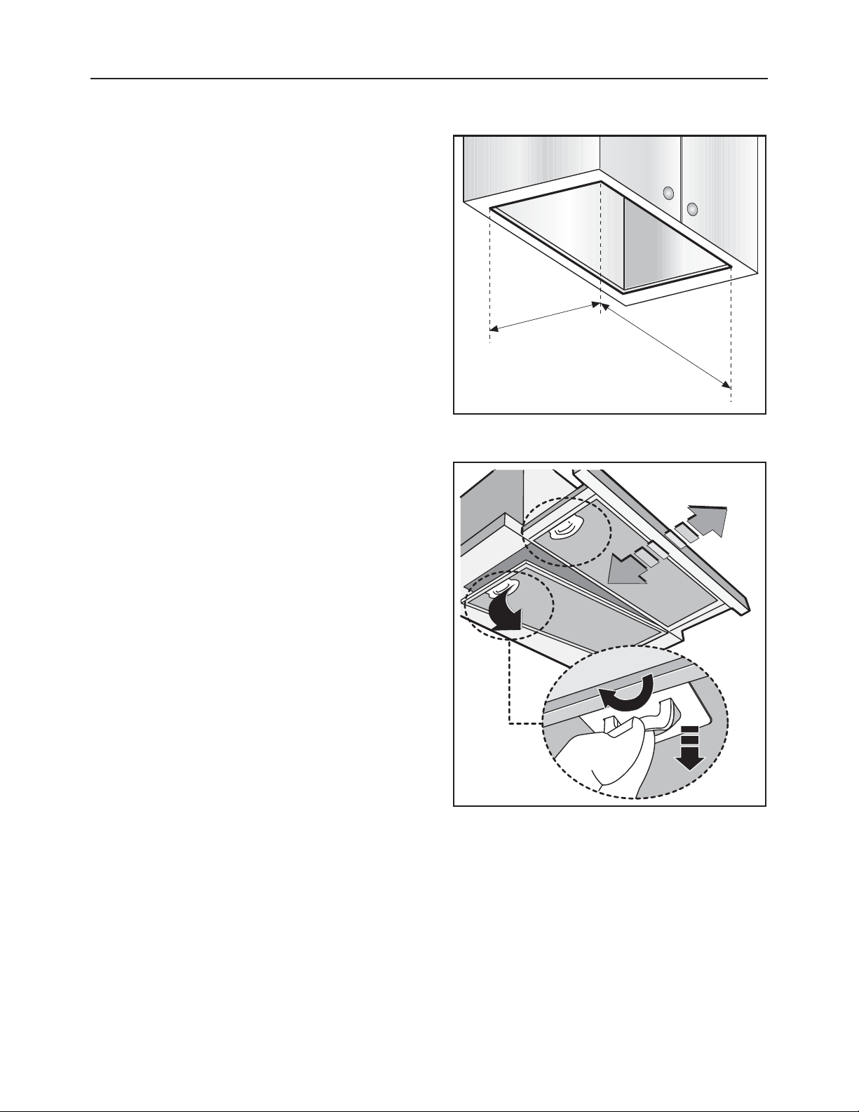
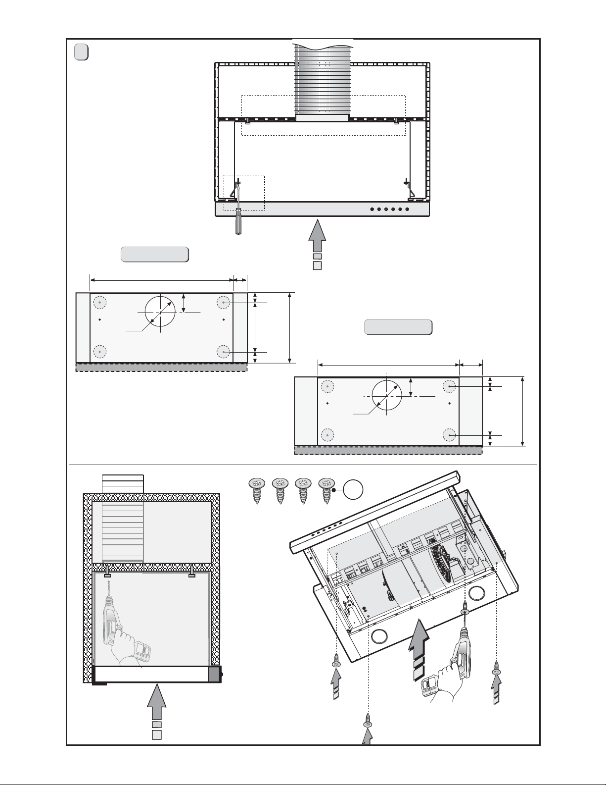
INSTALLATION INSTRUCTIONS
INSTALLATION VENTED TO THE OUTSIDE
Before proceeding with installation operations, remove the anti-grease filters (Fig.3)
in order to make handling the device
easier.
This product can be installed in 3 different
ways, depending on the model and on
your requirements:
1- installation of the hood on the lower
part of the wall unit.
2- installation of the hood on the lower
part of the wall unit on a divider support.
3- Installation of the hood on the lower
part of the wall unit only for 30".
Fig.2
11-1/4"
19-15/16"
31-3/4"
Fig.3
1
2
- 9 -
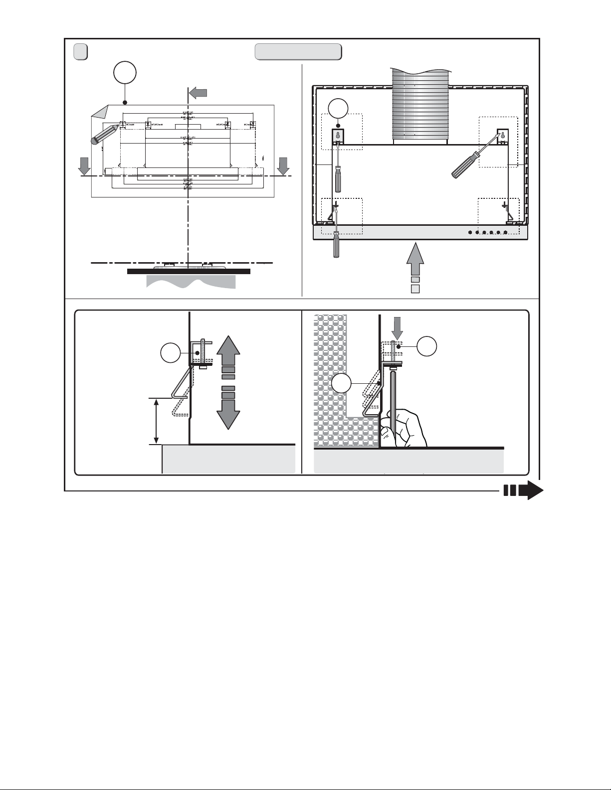
1
24" - 36" - 30"
B
A
3
4
2
Min 0-1/2"
Max 1/016"
2
2
1
F
F
M
Fig.4
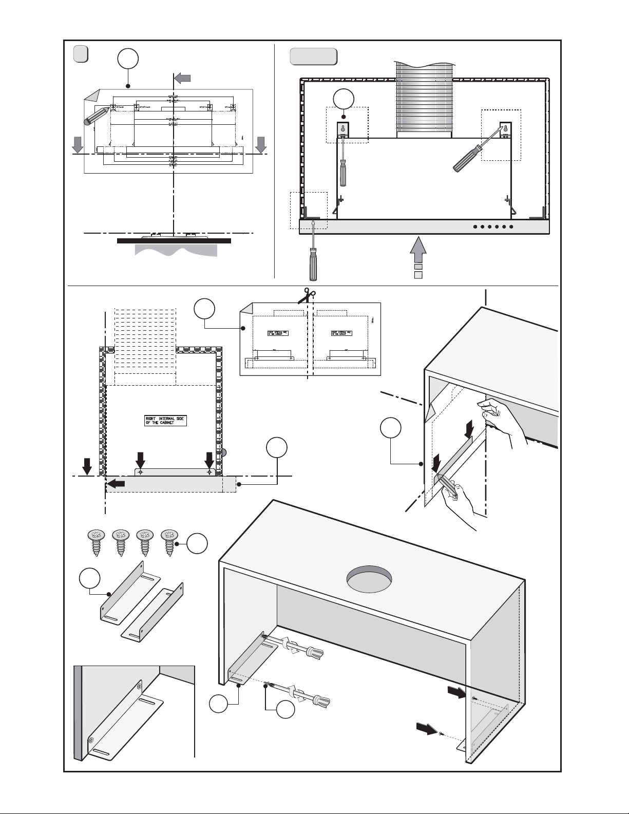
1. FIXING THE HOOD TO THE LOWER PART OF THE WALL CABINET:
Follow the steps below:
1- Position template B on the wall unit, bearing in mind the measurements indicated in
g. 1-2 and the minimum distance from the hob.
- Mark the references to x brackets A to the wall unit, as indicated in gure 4.
2- Make sure the thickness of the wall unit is within the parameters indicated in gure
4 - step 2.
3- Build the hood in the wall unit and make sure the 2 side springs F are connected correctly. Fasten the hood to the wall unit using the screwdriver and the relative screws M
and tighten until the device is rmly against the wall unit (gure 4 - step 2).
4- Remove pin Y from bracket A. Then place the insert X on the slot of the bracket A, as
indicated in gure 4 - step 3.
- Match the C screws with the L wascher and x the A bracket to the cabinet as indicated
in gure 4 - step 3.1. Pay attention not to completely tighten screws C before the bracket
- 10 -
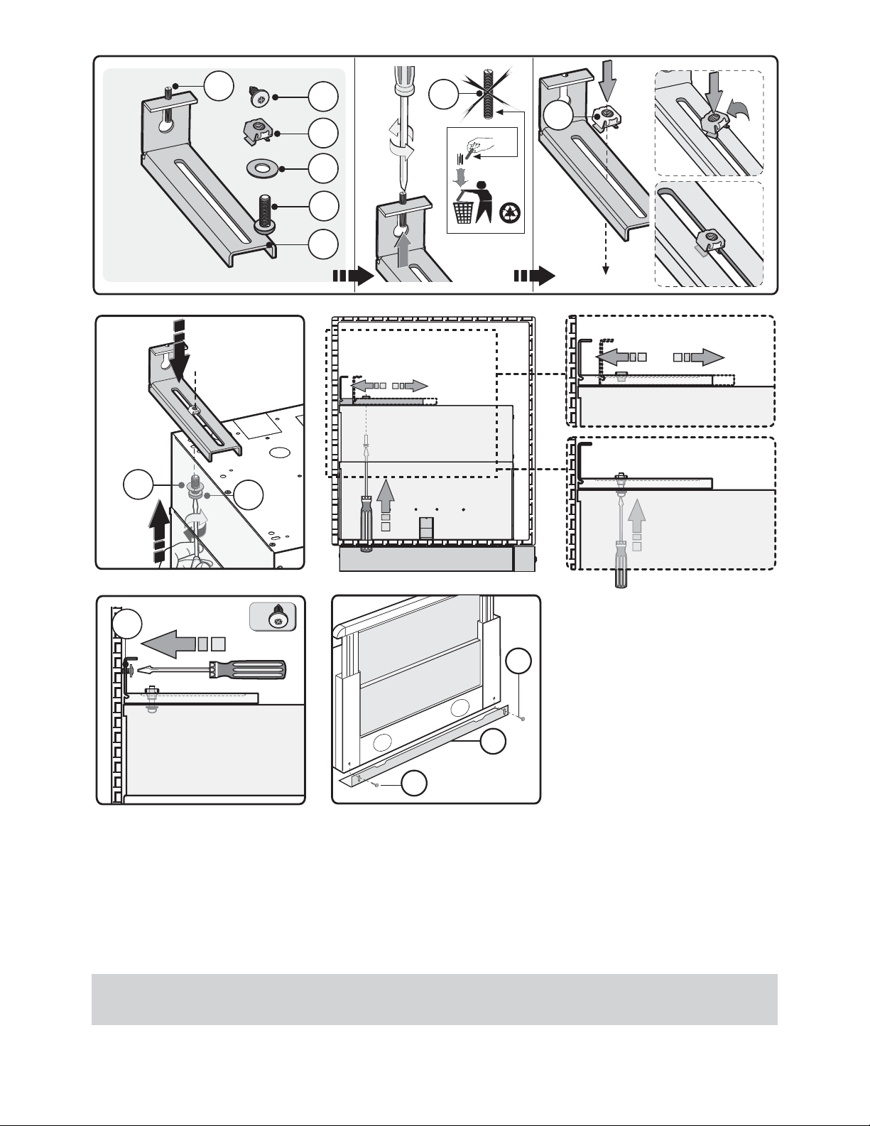
3
3.3
C
L
3.1
C
Y
D
X
L
C
A
Y
X
3.2
3.2
3.3
3.3
D
rmly reaches the wall unit (gure 4 - step 3.2). After any adjusting, tighten the bracket
to the body (gure 4 - step 3.3).
- Fasten screw D to the wall unit as indicated in gure 4 - step 4.
- Once you have fastened the hood to the wall unit, adjust the spacer L, with the screws
P, to make the device line up with the rear wall unit (gure 4 - step 5).
IMPORTANT - The range hood must be secured to wall studs or use drywall
anchors capable of supporting 75 lbs.
4
D
P
L
P
5
- 11 -

2. INSTALLATION OF THE HOOD ON THE LOWER PART OF THE WALL UNIT ON THE
DIVIDING PANEL.
Follow the steps below:
1 -Check the measurements indicated in fig.1-2 and the minimum distance from the hob,
before installing the hood on the dividing panel.
3- Make sure the thickness of the wall unit is within the parameters indicated in figure
4 - step 2.
4- Build the hood in the wall unit and make sure the 2 side springs F are connected
correctly. Fasten the hood to the wall unit using the screwdriver and the relative screws
M and tighten until the device is firmly against the wall unit (figure 4 - step 2).
5- Fasten the hood to the upper wall unit as indicated in figure 5 - step 6.
- Once you have fastened the hood to the wall unit, adjust the spacer L, with screws P, to
make the device line up with the rear wall unit (figure 4 - step 5).
IMPORTANT - The range hood must be secured to wall studs or use drywall
anchors capable of supporting 75 lbs.
- 12 -
2
6
2
1
24" - 36"
19-11/16" (24")
31-1/2" (36")
3-13/16"
1-15/16" (24"-36")
1-11/16"
Ø 6"
7-11/16"
1-11/16"
11-1/16"
19-11/16" (30")
Ø 6"
30"
3-13/16"
5-1/8" (30")
1-11/16"
7-11/16"
11-1/16"
1-11/16"
D
6
Fig.5
6
- 13 -
3
B
30"
A
3
4
7
1
E
G
1
D
G
E
E
2
D
3
Fig.6
- 14 -
G
30"
E
E
5
4
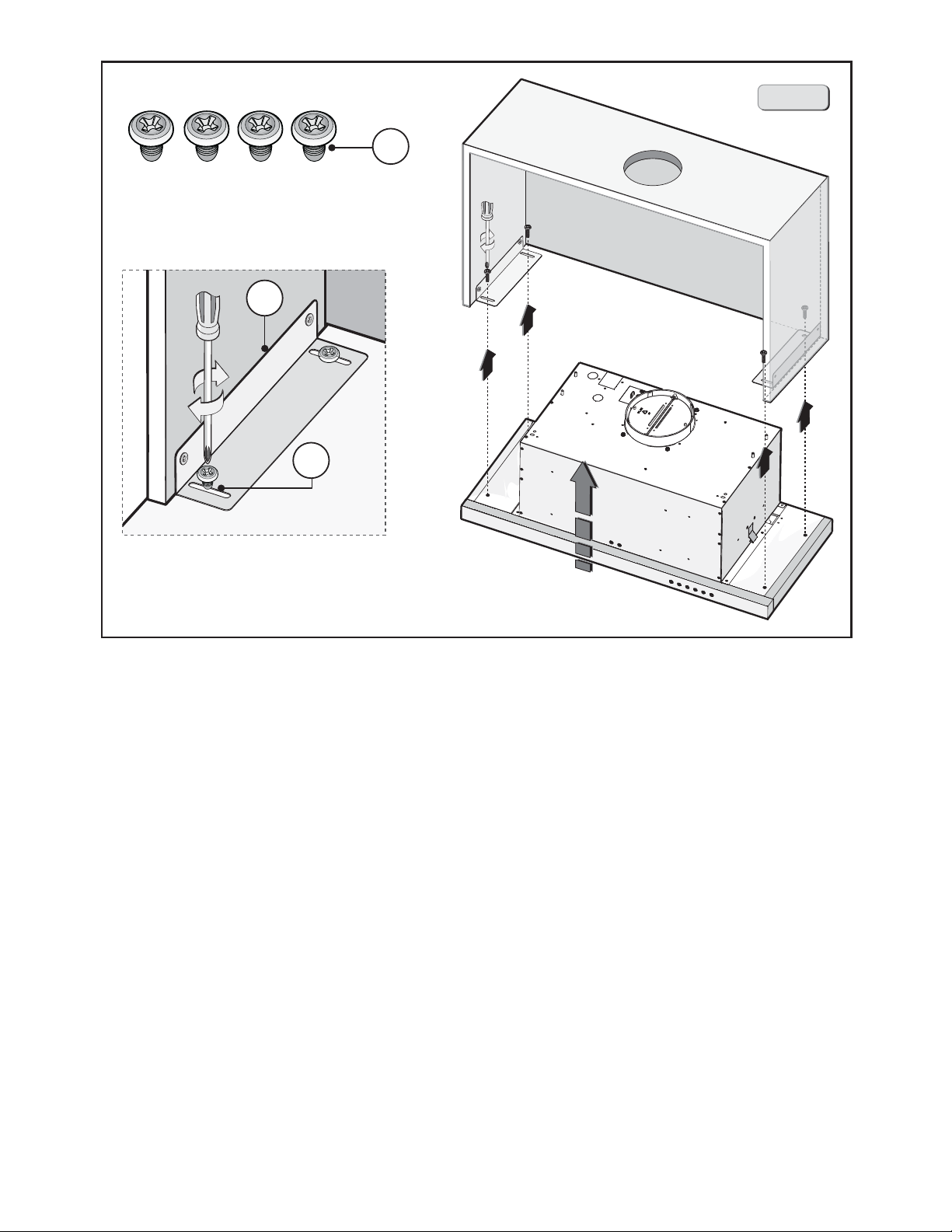
3. INSTALLATION OF THE HOOD ON THE LOWER PART OF THE WALL UNIT ONLY FOR
30".
This model includes side installation to the wall unit by using 2 brackets B (figure 6 besides
steps 3-4, indicated in figure 4).
1- Position template B on the wall unit, bearing in mind the measurements indicated in
fig. 1-2 and the minimum distance from the hob.
- Mark the references to fix brackets A to the wall unit, as indicated in figure 6.
2 - Position the second template E on the side of the wall unit and make sure that the line
matches up with that traced in figure 6 - step 1.
3 - Mark and drill the 4 fixing holes (figure 6 - step 2).
- Fasten the 2 brackets G to the wall unit using the 4 screws D (figure 6 - step 3).
- Fasten the hood to bracket G using the 4 screws E (figure 6 - step 4-5).
4- Remove pin Y from bracket A. Then place the insert X on the slot of the bracket A, as
indicated in figure 4 - step 3.
- Match the C screws with the L wascher and x the A bracket to the cabinet as indicated
in gure 4 - step 3.1. Pay attention not to completely tighten screws C before the bracket
firmly reaches the wall unit (figure 4 - step 3.2). After any adjusting, tighten the bracket
to the body (figure 4 - step 3.3).
- Fasten screw D to the wall unit as indicated in figure 4 - step 4.
- 15 -

- Once you have fastened the hood to the wall unit, adjust the spacer L, with screws P, to
make the device line up the rear wall unit (figure 4 - step 5).
IMPORTANT - The range hood must be secured to wall studs or use drywall
anchors capable of supporting 75 lbs.
- 16 -
POWER SUPPLY:
IMPORTANT – (Please read carefully)
WARNING:
FOR PERSONAL SAFETY, THIS APPLIANCE MUST BE PROPERLY GROUNDED.
Remove house fuse or open circuit breaker before beginning installation. Do not use an
extension cord or adapter plug with this appliance. Follow National electrical codes or
prevailing local codes and ordinances.
Electrical supply:
These vent hoods must be supplied with 120V, 60Hz, and connected to an individual,
properly grounded branch circuit, and protected by a 15 or 20 amp circuit breaker or
time delay fuse.
t 8JSJOHNVTUCFXJSFXJUIHSPVOE
t *G UIF FMFDUSJDBM TVQQMZ EPFT OPU NFFU UIF BCPWF SFRVJSFNFOUT DBMM B MJDFOTFE
electrician before proceeding.
t 3PVUFIPVTFXJSJOHBTDMPTFUPUIFJOTUBMMBUJPOMPDBUJPOBTQPTTJCMFJOUIFDFJMJOHPS
back wall. Refer to Wiring Locations on page 18.
t $POOFDUUIFIPPEXJSJOHUPUIFIPVTFXJSJOHJOBDDPSEBODFXJUIMPDBMDPEFT
WARNING: The improper connection of the equipment-grounding conductor
can result in a risk of electric shock. Check with a qualied electrician or service representative if you are in doubt whether the appliance is properly grounded.
- 17 -
2. CONNECT ELECTRICAL:
t 1PXFS4VQQMZ$POOFDUJPO
For connection to the power supply refer to the
follows Fig.7:
BLACK = L line
WHITE = N neutral
GREEN/YELLOW = G ground
- A double-pole switch properly rated must be
installed to provide the range hood power supply
disconnection.
- Connect the electrical conduit to the Field Wiring
Compartment using listed conduit ttings.
- Carry out the power supply connection in accordance with the national electric code, ANSI/NFPA
70-1999.
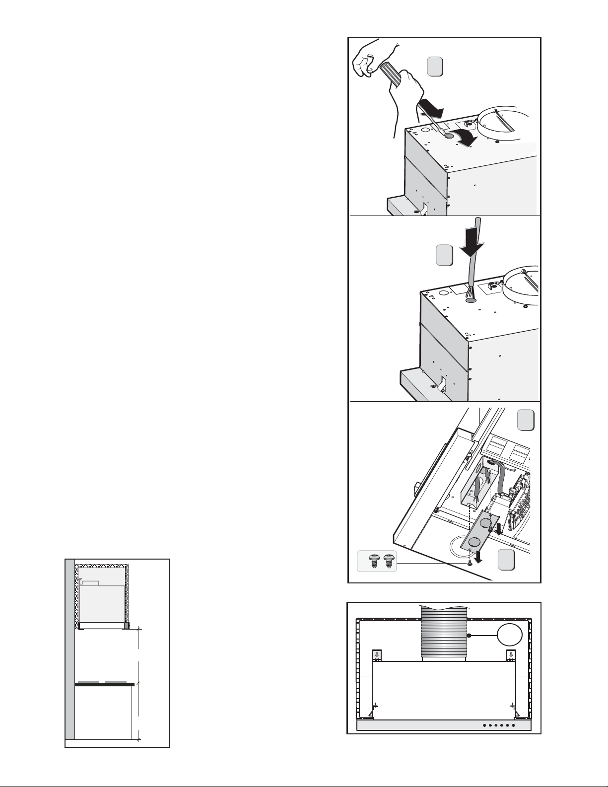
5. Insert the wires into the box, then close the box
cover, securing it using the s cr ew s th a t we re
previously removed.
The appliance should be installed at a minimum
height of 27" up to a maximum height of 32" for optimal performance. If a connection ductwork composed of two parts is used, the upper part must be
placed outside the lower part. Do not connect the
range hood exhaust duct air to the same duct air
used to exhaust hot air or fumes from other appliances other than electrical.
tIn the FILTERING version it is necessary to apply a
metal air exhaust tube M (Fig.8), with a minimum
length of 15", connected to the ange of the collector. It must be positioned vertically and fastened
to a specic opening made on the top part of the
cabinet.
1
2
4
3. CONNECT THE DUCTWORK:
Min 27" - Max 32"
36"
- 18 -
A
Fig.7
Fig.8
3
M
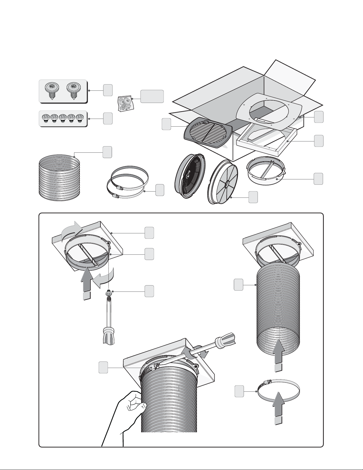
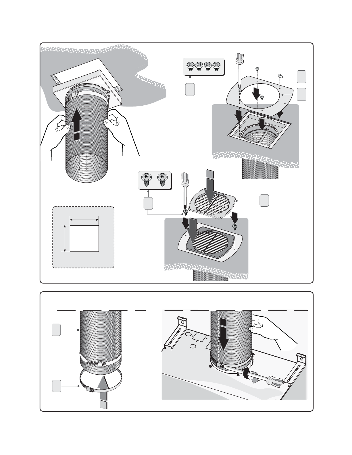
DUCTLESS RECIRCULATING OPTION:
CARBON FILTER KIT XOC24SMUA - XOC30SMUA - XOC36S - XOC30S : follow the indi-
cations described in the additional sheet to install the kit.
a
a-b
2
1
b
h
c
f
d
e
g
i
d
e
h
b
3
g
6
4
g
5
- 19 -
8
b
7-9/16"
6-3/4"
7
a
9
b
c
10
f
h
g
12
13
11
- 20 -
i
14
16
1
1
2
15
2
- 21 -

USE
t*GUIFBQQBSBUVTJTFRVJQQFEXJUIUIF
following controls luminous:
A = LIGHT
B = OFF
C = SPEED I
D = SPEED II
E = SPEED III
F =
AUTOMATIC STOP TIMER - 15 minutes (*)
tThe appliance has the INTENSIVE speed function, press key E for two seconds and it will
be activated for 10 minutes after which it will return to the previously set speed. When
the function is active the LED ashes. To interrupt it before the 10 minutes have expired
press key E again.
IMPORTANT: Intensive function is available only for model XOC36S - XOC30S
t By pressing key F for two seconds (with the hood switched o) the “clean air” function
is activated. This function switches the appliance on for ten minutes every hour at the
rst speed. As soon as this function is activated the motor starts up at the rst speed for
ten minutes. During this time key F and key C must ash at the same time.
After ten minutes the motor switches o and the LED of key F remains switched on with
a xed light until the motor starts up again at the rst speed after fty minutes and keys
F and C start to ash again for ten minutes and so on.
By pressing any key for the exclusion of the hood light the hood will return immediately
to its normal functioning (e.g. if key D is pressed the “clean air” function is deactivated
and the motor moves to the 2nd speed straight away. By pressing key B the function is
deactivated).
A
B
C
D
E
F
(*) The “automatic stop timer” delays stopping of the hood, which will continue functioning for 15 minutes at the operating speed set at the time this
t"DUJWFDBSCPOHSFBTFöMUFSTBUVSBUJPO
- When button A ashes at a frequency of 2 seconds, the grease lters must be cleaned.
- When button A ashes at a frequency of 0.5 seconds, the carbon lters must be replaced.
After the clean lter has been replaced, the electronic memory must be reset by pressing
button A for approximately 5 seconds, until the light on the button stops ashing.
- 22 -
function is activated.
MAINTENANCE
tWe recommend that the cooker hood is
switched on before any food is cooked.
We also recommend that the appliance is
left running for 15 minutes after the food
is cooked, in order to thoroughly eliminate
all contaminated air. The eective performance of the cooker hood depends on
constant maintenance; the anti-grease lter and the active carbon lter both require
special attention.
t5IFBOUJHSFBTFGJMUFS is used to trap
any grease particles suspended in the air,
therefore is subject to saturation (the time
it takes for the lter to become saturated
depends on the way in which the appliance is used). The grease lters should be
cleaned frequently. Use a warm detergent solution. Grease lters are a dishwasher safe.
- To prevent potential re hazards, the anti-grease lters should be washed a minimum
of every 2 months (it is possible to use the dishwasher for this task).
- After a few washes, the colour of the lters may change. This does not mean they have
to be replaced. If the replacement and washing instructions are not followed, the antigrease lters may present a re hazard.
t5IFBDUJWFDBSCPOöMUFST are used to purify the air which is released back into the room.
The lters are not washable or re-usable and must be replaced at least once every four
months. The active carbon lter saturation level depends on the frequency with which
the appliance is used, the type of cooking performed and the regularity with which the
anti-grease lters are cleaned.
tClean the cooker hood frequently, both inside and outside, using a cloth which has been
dampened with denatured alcohol or neutral, non-abrasive liquid detergents.
tThe light on the cooker hood is designed for use during cooking and not for general
room illumination. Extended use of the light reduces the average duration of the bulb.
Hood Cleaning:
Stainless steel is one of the easiest materilas to keep clean. Occasional care will help
preserve its ne appearance.
Cleaning tips:
- Hot water with soap or detergent is all that is usually needed.
- Follow all cleaningby rising with clear water. Wipe dry with a clean, soft cloth to avoid
water marks.
- For discolorations or deposit that persist, use a non-scratching household cleanser or
stainless steel polishing powder with a little water and a soft cloth.
- For stubborn cases, use a plastic scouring pad or soft bristle brush together with cleaser
and water. Rub lightly in direction of polishing lines or "grain" of the stainless finish. Avoid
using too much pressure wich may mar the surface.
- DO NOT allow deposit to remain for long periods of time.
Fig.9
1
2
G
- 23 -

- DO NOT use ordinary steel wool or steel brushes. Small bits of steel may adhere to the
surface causing rust.
- DO NOT allow salt solutions, disinfectants, bleaches, or cleaning compounds to remain
in contact with stainless steel for extended periods. Many of these compounds contain
chemicals with may be harmful. Rinse with water after exposure and wipe dry with a
clean cloth.
Painted surfaces should be cleaned with warm water and mild detergent only.
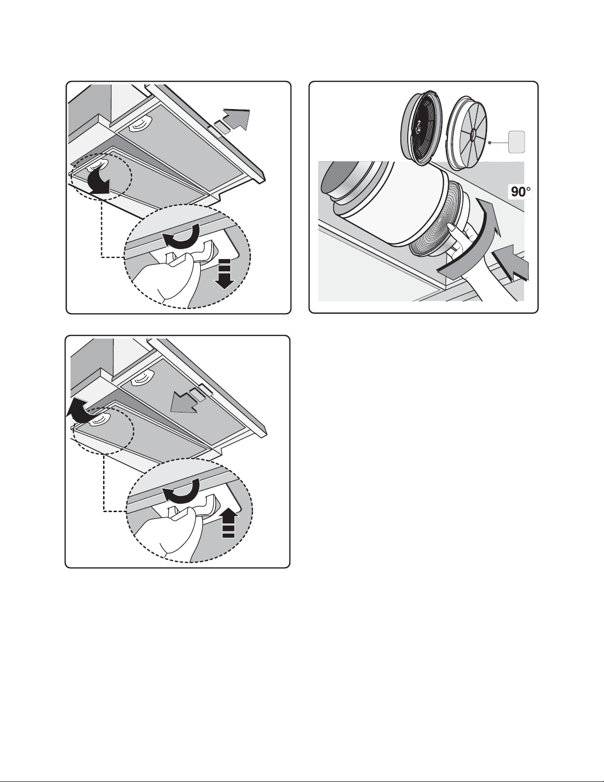
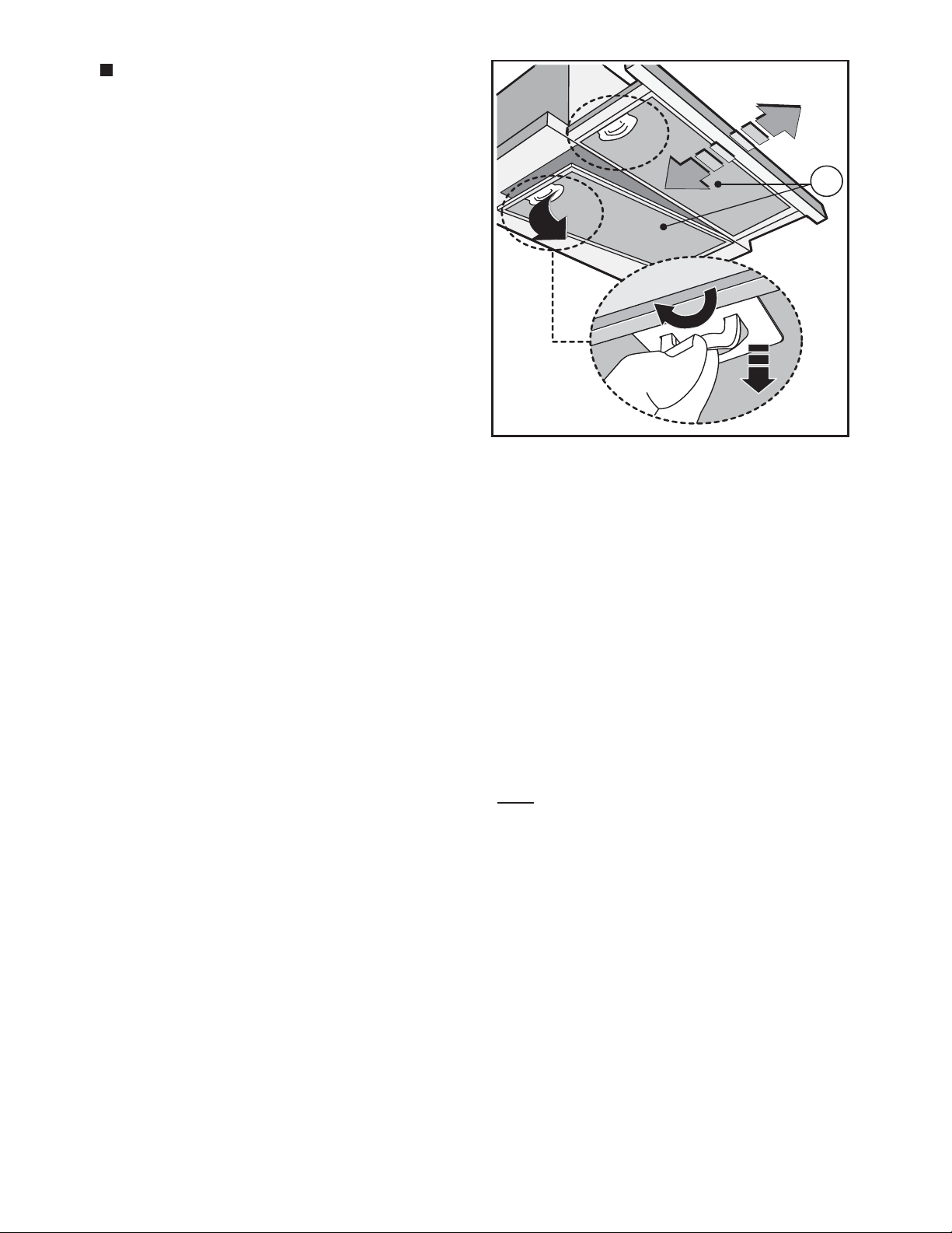
t 3FQMBDJOHUIFBMVNJOVNQBOFMT
To replace the aluminium panels, simply pull handle G as shown in Fig.9.
- 24 -
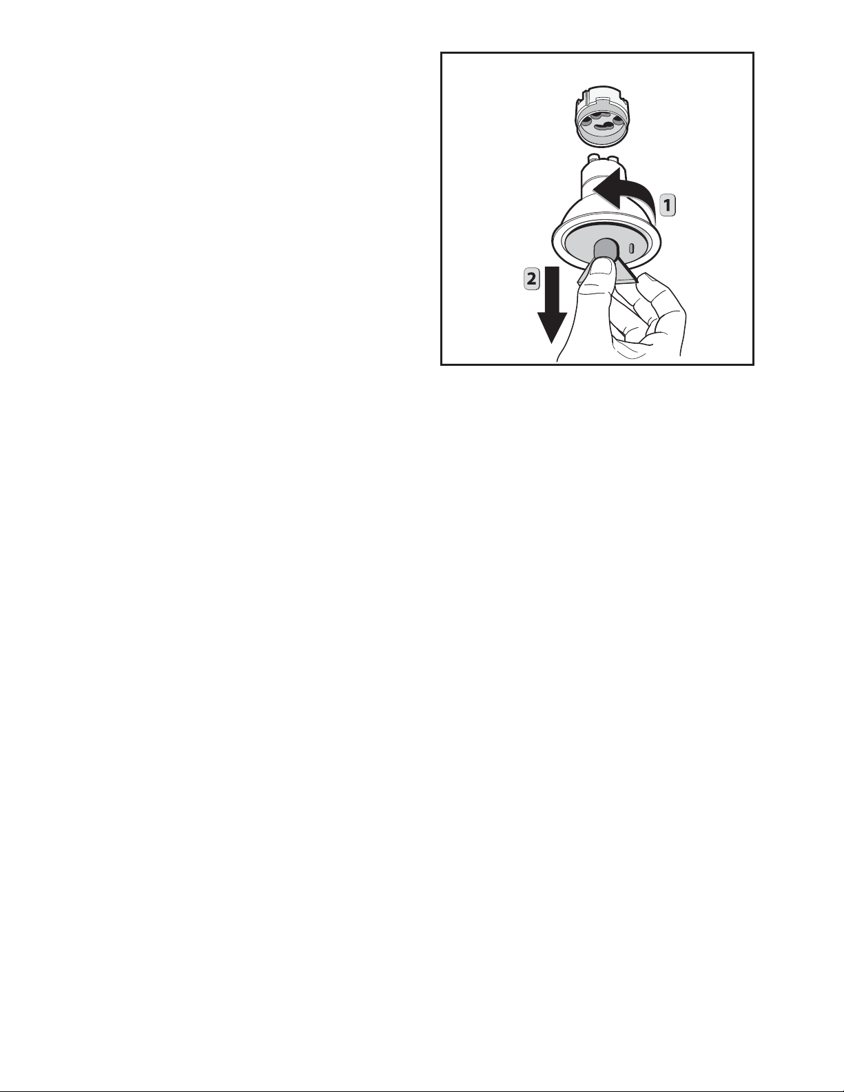
t3FQMBDJOHIBMPHFOMJHIUCVMCT
To replace the dichroic lamps, rotate the
lamp anticlockwise by means of a suction
cup as shown in gure.
Replace the bulbs with new ones of the
same type.
- 25 -
XOC24SMUA - XOC30SMUA - XOC36S - XOC30S:
530
173
110
261
39
160
- 26 -
70
609
40
140

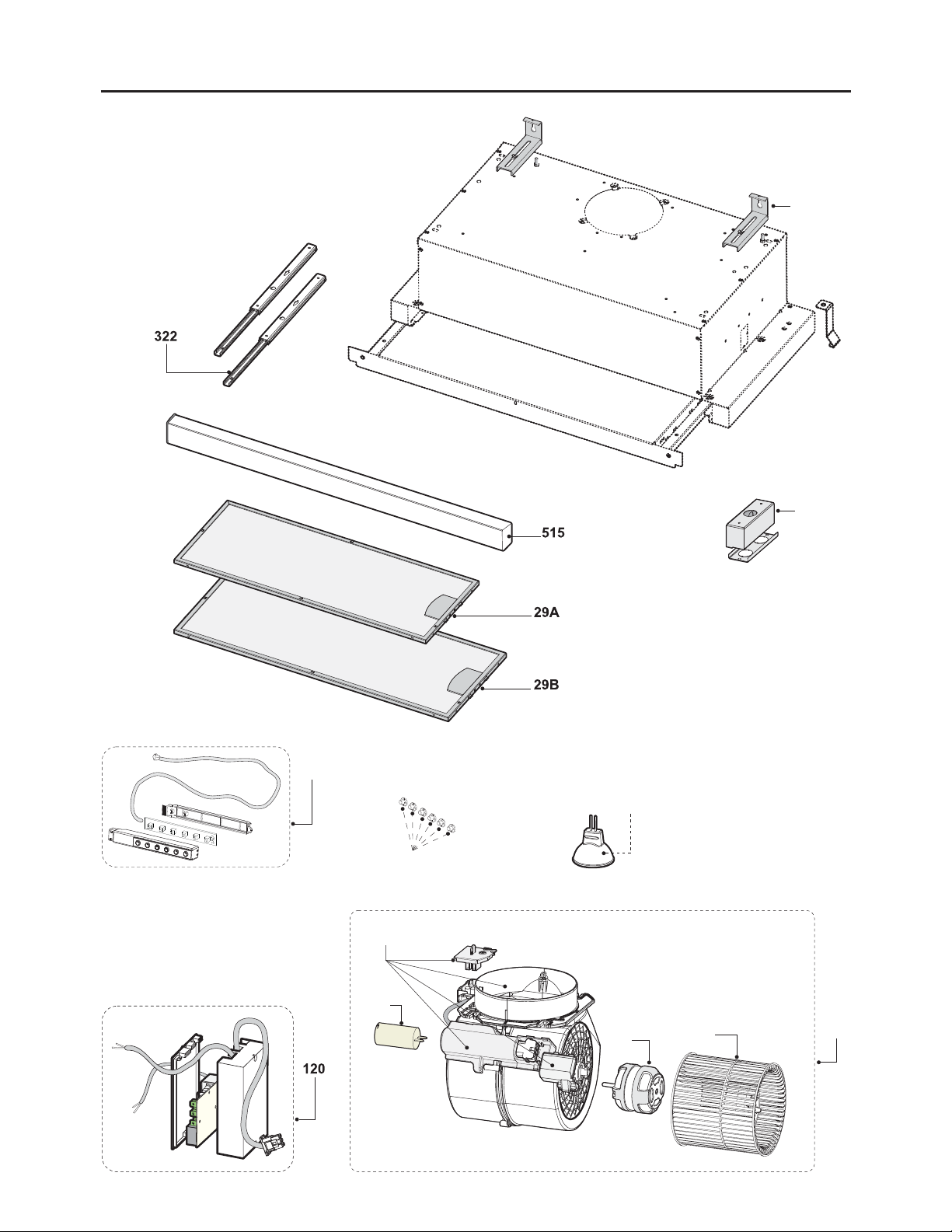
OPTIONS AND ACCESSORIES:
Model XORFRND Ductless Recirculating Filter Kit.
Model XORFK12 Ductless Recirculating Filter Kit.
- 27 -

INSTALLATION PREPARATION:
Check installation hardware:
Locate the hardware package packed with the hood and check contents.
TYPE DESCRIPTION N°
1/4"
A
1/8" x 1/4" 3
6/16"
B
3/16" x 9/16" 4
Adjusting brackets Aluminum lter
Supply of side xing brackets on wall unit only for 30"
1/8" x 1/4" N°4
3/16" x 9/16" N°4
1/4"
6/16"
Side fixing brackets on wall unit
no. 2.
- 28 -

XOC Spec Sheet
Model: XOC24SMUA - XOC30SMUA - XOC36S -
XOC30S
Sizes: 24" - 30" - 36" Depth: 11-1/16"
Features and Benets:
Model: XOC24SMUA - XOC30SMUA
- 395 CFM high velocity blower optimally removes
Smoke, Grease and Odors.
- 3 speed electronic illuminated controls.
Model: XOC36S - XOC30S
- 600 CFM high velocity blower optimally removes
Smoke, Grease and Odors.
- 3+1 speed electronic illuminated controls.
- Two 50W Halogen Lights - Provide brilliant
illumination over the cooking surface.
- Aluminum Mesh Filters - Trap airborne smoke and
grease particles. They can be easily be removed
for dishwasher-safe cleaning.
- Mounting Height from cooking surface 27”-32”
10-9/16"
11-1/16"
16-15/16"
19-11/16" - 31-1/2"
18-5/8" - 30-7/16"
Ø6"
11-1/16"
9-0/16"
Duct Options and Electrical Requirements:
- 6 inch duct required.
- Ductless Option for applications where no
ducting in available.
Model: XOC24SMUA - XOC30SMUA
- AC 120v-60Hz (3.5amp).
Model: XOC36S - XOC30S
- AC 120v-60Hz (4.35amp).
Options:
- Optional recirculating kit if outside venting is
unavailable.
Model: XORFRND - XORFK12
XO is Exclusively Distributed by:
Eastern Marketing Corp 24 Eisenhower Parkway Roseland,
New Jersey 07068 800-966-8300
www.easternmarketing.com
1-0/16"
1-9/16"
23-9/16" - 29-15/16" - 35-3/8"
www.xoappliace.com
- 29 -

Garantie hotte XO
Pour demander une intervention en garantie, la facture d’achat
est nécessaire.
Que couvre-t-elle ?
Que ne couvre-t-elle
pas ?
Garantie de deux ans.
La garantie couvre la réparation et le remplacement gratuitement
à votre domicile de pièces de la hotte avec des défauts dérivant
d’une erreur de fabrication, pour une période de deux ans à
compter de la date d’achat.
La garantie couvre les achats effectués pour un usage domestique
en Amérique du Nord.
Si vous avez besoin d’assistance pour votre produit XO, téléphonez
au numéro 800.966.8300
Installation incorrecte.
Visites à votre domicile pour vous conseiller sur comment utiliser
le produit.
Réinitialisation des interrupteurs.
Dommages causés après la livraison.
VOUS DEVEZ VOUS ATTENDRE QUELQUE CHOSE DE PLUS
D’UN XO
En achetant un produit XO
vous pouvez être certain
d’avoir acheté un produit de grande qualité,
innovant et agréable à regarder
d’une entreprise qui reste à vos côtés.
- 30 -

FRANÇAIS
INSTRUCTIONS DE SECURITE IMPORTANTES
POUR UN USAGE DOMESTIQUE EXCLUSIVEMENT
LIRE ET CONSERVER LES INSTRUCTIONS
COMMENCER PAR LIRE ENTIEREMENT LES INSTRUCTIONS.
IMPORTANT: Conserver les Instructions à usage des Inspecteurs Electriques
Locaux.
A L’ATTENTION DE L’INSTALLATEUR: Laisser les Instructions dans l’unité à usage du
propriétaire.
A L’AT TENTION DU PROPRIETAIRE: Conserver les Instructions pour des consultations
ultérieures.
N’utiliser des produits de nettoyage ou des détergents qu’avec la plus grande
prudence.
Cet appareil est propre à une utilisation domestique et culinaire.
F
AVERTISSEMENT – An de réduire les risques d’incendie ou d’électrocution, ne pas
utiliser le moteur avec un Dispositif de Contrôle de la Vitesse à Semi-conducteurs
quel qu’il soit.
ATTENTION – An de réduire les risques d’incendie et de permettre une aspiration
correcte de l’air, s’assurer que celui-ci est bien transporté à l’extérieur à travers un
conduit d’évacuation. – Ne pas évacuer l’air dans des interstices tels qu’entre des
cloisons ou des plafonds, dans des greniers, des espaces connés ou des garages.
ATTENTION – N’utiliser que pour une ventilation générique. Cet appareil n’est pas
propre à l’aspiration de matières ou de vapeurs dangereuses ou explosives.
ATTENTION – An d’éviter des bruits et des dommages au niveau du moteur, et/ou
un déséquilibre au niveau des hélices, veiller à ce que l’unité d’alimentation n’entre
pas en contact avec du spray, de la poussière etc.
ATTENTION – Pour obtenir des compléments d’informations, consulter l’étiquette
de spécication sur le produit.
AVERTISSEMENT – AFIN DE RÉDUIRE LES RISQUES D’INCENDIE, D’ÉLECTROCUTION
OU DE DOMMAGES AUX PERSONNES, RESPECTER LES REGLES SUIVANTES :
A. N’utiliser l’unité que pour les opérations prévues par le fabricant. Pour toute question
éventuelle, contacter le fabricant.
B. Avant d’eectuer des opérations de maintenance ou de nettoyage sur l’unité,
- 31 -

débrancher le panneau de service et fermer à clef les commandes de déconnection
an d’éviter toute mise sous tension accidentelle.
Au cas où les commandes de déconnection ne pourraient être fermées à clef, xer sur
lepanneau de service un message avertissant du danger, par exemple une plaque.
AVERTISSEMENT – AFIN DE RÉDUIRE LES RISQUES D’INCENDIE PAR
INFLAMMATION DES GRAISSES PRESENTES SUR LA GAZINIERE :
A. Ne jamais laisser de casseroles sur feu vif sans surveillance. D’éventuels débordements
dus à une forte ébullition peuvent provoquer de la fumée et des dépôts de graisses
susceptibles de prendre feu. Réchauer l’huile lentement, à petit feu ou moyen.
B. ALLUMER systématiquement la hotte pour cuisiner à des températures élevées ou
pour amber des aliments (ex. : Crêpes Suzette, Cherries Jubilee – cerises ambées au
brandy et glace -, Boeuf ambé au poivre).
C. Nettoyer souvent le moteur. Eviter que les graisses ne s’accumulent sur le moteur ou
sur le ltre.
D. Utiliser des plats aux dimensions adaptées. Toujours utiliser des ustensiles de cuisine
adaptés à la taille de la casserole qui se trouve sur la cuisinière.
E. Veiller à ce que le moteur, les ltres et la surface où viennent s’accumuler les graisses
restent propres.
F. N’utiliser une amme élevée que lorsque cela est nécessaire. Réchauer l’huile
lentement, à faible ou moyenne température.
G. Ne jamais laisser la cuisinière sans surveillance pendant la cuisson.
H. Utiliser systématiquement des ustensiles de cuisine adaptés au type et à la quantité
d’aliments que l’on prépare.
AVERTISSEMENT – AFIN DE RÉDUIRE LES RISQUES DE DOMMAGES AUX PERSONNES
EN CAS D’INCENDIE PAR INFLAMMATION DES GRAISSES PRESENTES SUR LA CUISINIERE,
RESPECTER LES REGLES SUIVANTESa:
A. ETOUFFER LA FLAMME à l’aide d’un couvercle hermétique, une plaque à four ou un
plateau en métal et éteindre le brûleur. PROCEDER AVEC LA PLUS GRANDE PRUDENCE
AFIN D’EVITER TOUTE BRULURE. Si les ammes ne s’éteignent pas immédiatement,
EVACUER LA PIECE ET APPELER LES POMPIERS.
B. NE JAMAIS TOUCHER UN PLAT EN FEU – on risque de se brûler.
C. NE PAS UTILISER D’EAU, ni de chions ou de serviettes humides – cela pourrait
provoquer une violente explosion de vapeur.
D. Utiliser un extincteur UNIQUEMENT dans les cas suivants:
1. On dispose d’un extincteur de Classe ABC que l’on sait faire fonctionner.
2. L’incendie est peu important et il est conné à la zone où il a éclaté.
3. On a déjà appelé les pompiers.
4. On peut aronter les ammes tout en ayant une issue de secours derrière soi.
aBasé sur les « mesures de sécurité incendie dans la cuisine « publiées par l’organisme
NFPA.
Une bonne maintenance de la hotte garantit le parfait fonctionnement de l’unité.
- 32 -

INSTRUCTIONS D’INSTALLATION
AVERTISSEMENT – AFIN DE RÉDUIRE LES RISQUES D’INCENDIE, D’ÉLECTROCUTION
OU DE DOMMAGES AUX PERSONNES, RESPECTER LES REGLES SUIVANTES :
A. Les opérations d’installation et de branchement électrique doivent être eectuées
par du personnel qualié, conformément aux lois et aux normes en vigueur, y
compris celles relatives aux appareils à feu.
B. Il est nécessaire de disposer d’une quantité d’air susante pour une bonne
combustion et aspiration des gaz à travers le conduit de fumée de l’installation
de combustion du carburant, an d’éviter un appel d’air de l’arrière. Suivre les
indications du fabricant de l’installation de chauage et les normes de sécurité
correspondantes telles que celles émises par l’Association Nationale de Protection
contre les Incendies (National Fire Protection Association - NFPA), la Société
Américaine des Techniciens de Chauage, Réfrigération et Climatisation de l’Air
(American Society for Heating, Refrigeration and Air Conditioning Engineers -
ASHRAE), et par les autorités locales préposées.
C. Au cours des opérations de découpage ou de perforation du mur ou du plafond,
veiller à ne pas endommager les câbles électriques ou d’autres canalisations
cachées.
D. L’appareil doit toujours être relié à un trou d’évacuation vers l’extérieur.
E. L’unité doit être reliée à la terre.
AVERTISSEMENT – AFIN DE RÉDUIRE LES RISQUES D’INCENDIE, N’UTILISER QUE
DESCONDUITS METALLIQUES
AVERTISSEMENT – LES APPAREILS ELECTROMENAGERS PEUVENT PARFOIS S’AVERER
DANGEREUX.
A. Ne pas contrôler les ltres lorsque la hotte est en état de marche.
B. Ne pas toucher les lampes après une utilisation prolongée de l’appareil.
C. Ne jamais faire amber d’aliments sous la hotte.
D. L’usage de ammes libres est dangereux pour les ltres et peut générer des incendies.
E. Contrôler constamment les fritures pour éviter que des éclaboussures d’huile ne
prennent feu.
F. Avant d’eectuer toute opération de maintenance, débrancher la hotte du réseau
d’alimentation électrique.
Le fabricant ne pourra être retenu responsable d’éventuels dommages causés par le
non respect des instructions susmentionnées.
- 33 -

RACCORDS DE
CANALISATION:
Cette hotte doit utiliser
un conduit rond de 20
cm (8 po) raccordan
à un tuyau 8 cm x 30
cm (3-1/4" po x 12 po).
Reportez-vous au tableau
pour calculer les longueurs maximales autorisées
pour les conduits vers l’extérieur.
Préparation à l'installation
REMARQUE: Ne dépassez
pas les longueurs maximales
autorisées!
Longueur maximale de
conduit: 30 m (100 pi)
pour les hottes de cuisinière.
Conduit: Dimensions:
Rond droit
Droit 8 cm x 30
cm (3-1/4 po x
12 po)
Coude 90°
Coude 45°
Coude 90° 8 cm
x 30 cm (3-1⁄4
po x 12 po)
Coude 45° 8 cm
x 30 cm (3-1/4
po x 12 po)
Coude plat 90°
8 cm x 30 cm
(3-1/4 po x 12
po)
Longueur
équivalente*:
30 cm (1 pied)
(par longueur
en pied)
30 cm (1 pied)
(par longueur
en pied)
5 m (17
pieds)
3 m (10
pieds)
13 m (43
pieds)
7,90 m (26
pieds)
32 m (102
pieds)
Quantité
utilisée:
Longueur
total
équivalente:
Conduit flexible:
En cas d’utilisation de conduits métalliques flexibles,
les valeurs en pieds figurant
dans le tableau doivent
être doublées. Le conduit
métallique flexible doit
être droit et lisse et étiré au
maximum.
N’utilisez PAS de conduit en
plastique flexible.
REMARQUE: Tout système
de ventilation domestique
tel qu’une hotte aspirante,
est susceptible d’interrompre
le débit d’air et de fumées
de combustion requis pour
les cheminées, fours à gaz,
les chauffe-eau à gaz et autres systèmes naturellement
ventilés. Afin de réduire les
probabilités d’interruption
de ces systèmes naturellement ventilés, nous vous
recommandons de suivre
les consignes du fabricant de
l’équipement de chauffage
et les normes de sécurité
telles que celles publiées par
la NFPA.
Rond 20 cm
(8 po) pour
raccord 8 cm x
30 cm (3-1/4 po
x 12 po)
8 cm x 30 cm
(3-1/4 po x
12 po) pour
raccord rond 20
cm (8 po)
Rond 20 cm
(8 po) pour
raccord en
coude 90° 8 cm
x 30 cm (3-1/4
po x 12 po)
8 cm x 30 cm
(3-1/4 po x
12 po) pour
raccord rond 20
cm (8 po) en
coude 90°
Cache mur rond
avec registre
Cache mur 9
cm x 30 cm (31/4 po x 12 po)
avec registre
Cache rond
pour toiture
*Longueur réelle du conduit droit plus le raccord
de conduit équivalent. Longueur équivalente des
conduits satisfait aux exigences pour de bonnes
performances en termes de ventilation de toute
hotte aspirante.
60 cm (2
pieds)
1,5 m (5
pieds)
1,8 m (6
pieds)
3,96 m (13
pieds)
9,7 m (32
pieds)
22,9 m (75
pieds)
13 m (44
pieds)
Parcours total
des conduits =
- 34 -

AVERTISSEMENT: DANGER D’INCENDIE
N’installez JAMAIS le conduit d’évacuation de l’air dans les interstices des murs,
vides sanitaires, attiques ou garages.
L’air doit toujours être évacué à l’extérieur sauf si on opte pour l’option de la
recirculation.
Utilisez exclusivement des conduits en métal rigide à simple paroi.
Procédez à toutes les connexions en vous servant des vis auto-taraudeuses et
appliquez du ruban adhésif américain certié sur toutes les jonctions.
Installation – Options D’aspiration
INSTALLATION DES TUYAUX:
NOTE: pour diminuer le risque d’incendie, utiliser uniquement des tuyaux en
métal.
1. Décider la position du tuyau entre la hotte et l’extérieur.
2. Un tuyau court et droit améliore les performances de la hotte.
3. De longs tuyaux, des coudes et des raccords en diminuent les performances.
Utiliser ces éléments le moins possible.
4. Installer une cheminée au toit ou au mur. Raccorder un tuyau en métal circulaire
à la cheminée et procéder vers la hotte (de haut en bas). Utiliser du ruban isolant
pour les tuyaux pour sceller les jonctions entre les diérentes sections.
- 35 -

DIMENSIONS DU PRODUIT ET DISTANCES
XOI27S:
Partie avant de la hotte Partie latérale de la hotte
18-5/8" (24" - 30")
30-7/16" (36")
Specications Techniques
23-9/16" (24") - 29-15/16" (30") - 35-3/8" (36")
9"
12-1/8"
1-9/16"
11-1/16"
1-3/16"
16-15/16"
L
min 0 - 0/16" - max 1 - 4/16"
min 0 - 0/16" - max 1 - /4"
Partie supérieure de la hotte Hauteur de montage
19-11/16" (24")
1-15/16" (24"-36")
et distances :
31-1/2" (36")
Ø 6"
Ø 6"
3-13/16"
19-11/16" (30")
3-13/16"
1-11/16"
2-9/16"
5-1/8"
1-11/16"
5-1/8" (30")
1-11/16"
2-9/16"
5-1/8"
1-11/16"
11-1/16"
Min 27" - Max 32"
36"
11-1/16"
Fig.1
- 36 -

INSTRUCTIONS POUR L’INSTALLATION
INSTALLATION AVEC ÉVACUATION VERS L’EXTÉRIEUR
Avant de procéder aux opérations de montage, pour facilité la manœuvrabilité de
l'appareil, retirer le(s) filtre(s) anti-graisse
(Fig.3).
Ce produit peut être installé de 3 façons
différentes selon le modèle et vos besoins :
1- montage de la hotte dans la partie inférieure du meuble suspendu.
2- Montage de la hotte dans la partie inférieure du meuble suspendu sur support
de séparation.
3- Montage de la hotte dans la partie inférieure du meuble suspendu uniquement
pour le 30".
11-1/4"
Fig.2
19-15/16"
31-3/4"
- 37 -
1
2
Fig.3

1
24" - 36" - 30"
B
A
3
4
2
Min 0-1/2"
Max 1/016"
2
2
1
F
F
M
Fig.4
1. FIXATION DE LA HOTTE SOUS UN ÉLÉMENT HAUT:
Pour un bon montage, suivre les étapes suivantes :
1 - Positionner le gabarit B au meuble suspendu en tenant compte des mesures indiquées
sur la fig. 1-2 et de la distance minimale du plan de cuisson.
- Marquer les références pour la fixation des étriers A au meuble suspendu comme indiqué
sur la figure 4.
2 - Faire attention à ce que l'épaisseur du meuble suspendu soit comprise dans les valeurs
indiquées sur la figure 4 - étape 2.
3 - Encastrer la hotte dans le meuble suspendu et faire attention à ce que les 2 ressorts
latéraux F soient bien accrochés, fixer définitivement la hotte au meuble suspendu en
vissant les vis M à l'aide d'un tournevis jusqu'à porter l'appareil en butée avec le meuble
suspendu figure 4 - étape 2.
4 - Prendre l'étrier A et retirer le pivot Y, prendre ensuite l'insert X et le positionner sur la
fente de l'étrier A comme indiqué sur la figure 4 - étape 3.
- 38 -

3
3.3
C
L
3.1
C
Y
D
X
L
C
A
Y
X
3.2
3.2
3.3
3.3
D
- Apparier la vis C avec la rondelle L et fixer l'étrier à la coque comme indiqué sur la figure
4 - étape 3.1. Faire attention à ne pas serrer complètement la vis C, avant il faut porter
l'étrier en butée avec le meuble suspendu figure 4 - étape 3.2, lorsque le réglage a été
effectué, serrer définitivement l'étrier à la coque figure 4 - étape 3.3.
- Prendre la vis D, l'incliner et la fixer au meuble suspendu comme indiqué sur la figure
4 - étape 4.
- Une fois fixée la hotte au meuble suspendu, régler l'entretoise L, à l'aide des vis P, pour
faire coïncider à l'arrière l'appareil au meuble suspendu figure 4 - étape 5.
4
D
P
L
P
5
IMPORTANT: La hotte doit être xée au mur avec des pivots de support letés
ou des chevilles d’une capacité de 75 lbs.
- 39 -

2. MONTAGE DE LA HOTTE DANS LA PARTIE INFÉRIEURE DU MEUBLE SUSPENDU
SUR PANNEAU DE SEPARATION.
Pour un bon montage, suivre les étapes suivantes :
1 - Avant de monter la hotte au panneau de séparation, contrôler les mesures indiquées
sur la fig. 1-2 et la distance minimale du plan de cuisson.
3 - Faire attention à ce que l'épaisseur du meuble suspendu soit comprise dans les valeurs
indiquées sur la figure 4 - étape 2.
4 - Encastrer la hotte dans le meuble suspendu et faire attention à ce que les 2 ressorts
latéraux F soient bien accrochés, fixer définitivement la hotte au meuble suspendu en
vissant les vis M à l'aide d'un tournevis jusqu'à porter l'appareil en butée avec le meuble
suspendu figure 4 - étape 2.
5 - Fixer la hotte au meuble suspendu supérieur comme indiqué sur la figure 5 - étape 6.
- Une fois fixée la hotte au meuble suspendu, régler l'entretoise L, à l'aide des vis P, pour
faire coïncider à l'arrière l'appareil au meuble suspendu figure 4 - étape 5.
IMPORTANT: La hotte doit être xée au mur avec des pivots de support letés
ou des chevilles d’une capacité de 75 lbs.
- 40 -

2
6
2
1
24" - 36"
19-11/16" (24")
31-1/2" (36")
3-13/16"
1-15/16" (24"-36")
1-11/16"
Ø 6"
7-11/16"
1-11/16"
11-1/16"
19-11/16" (30")
Ø 6"
30"
3-13/16"
5-1/8" (30")
1-11/16"
7-11/16"
11-1/16"
1-11/16"
D
6
Fig.5
6
- 41 -

3
B
30"
A
3
4
7
1
E
G
1
D
G
E
E
2
D
3
Fig.6
- 42 -

G
30"
E
E
5
4
3. MONTAGE DE LA HOTTE DANS LA PARTIE INFÉRIEURE DU MEUBLE SUSPENDU
UNIQUEMENT POUR LE 30".
Le montage latéral au meuble suspendu est prévu pour ce modèle, au moyen des 2 étriers
figure 6, en plus des étapes 3-4 indiquées sur la figure 4.
1 - Positionner le gabarit B au meuble suspendu en tenant compte des mesures indiquées
sur la fig. 1-2 et de la distance minimale du plan de cuisson.
- Marquer les références pour la fixation des étriers A au meuble suspendu comme indiqué
sur la figure 6.
2 - Prendre le second gabarit E et le positionner sur le coté du meuble suspendu en faisant
attention à ce que la ligne coïncide avec celle tracée sur la figure 6 - étape 1.
3 - Marquer et effectuer les 4 trous de fixation figure 6 - étape 2.
- Fixer les 2 étriers G au meuble suspendu à l'aide des 4 vis D figure 6 - étape 3.
- Prendre la hotte et la fixer définitivement à l'étrier G à l'aide des 4 vis E figure 6 - étape 4-5.
4 - Prendre l'étrier A et retirer le pivot Y, prendre ensuite l'insert X et le positionner sur la
fente de l'étrier A comme indiqué sur la figure 4 - étape 3.
- Apparier la vis C avec la rondelle L et fixer l'étrier à la coque comme indiqué sur la figure
4 - étape 3.1. Faire attention à ne pas serrer complètement la vis C, avant il faut porter
l'étrier en butée avec le meuble suspendu figure 4 - étape 3.2, lorsque le réglage a été
effectué, serrer définitivement l'étrier à la coque figure 4 - étape 3.3.
- 43 -

- Prendre la vis D et la fixer au meuble suspendu comme indiqué sur la figure 4 - étape 4.
- Une fois fixée la hotte au meuble suspendu, régler l'entretoise L, à l'aide des vis P, pour
faire coïncider à l'arrière l'appareil au meuble suspendu figure 4 - étape 5.
IMPORTANT: La hotte doit être xée au mur avec des pivots de support letés
ou des chevilles d’une capacité de 75 lbs.
- 44 -

ALIMENTATION:
IMPORTANT (veuillez lire attentivement)
MISE EN GARDE:
POUR VOTRE SECURITE, L’APPAREIL DOIT ETRE MIS SUR LE SOL.
Avant de commencer l’installation, éliminer le fusible ou ouvrir l’interrupteur du circuit.
Ne pas utiliser de rallonges et de prises d’adaptation avec cet appareil. Veuillez vous en
tenir aux codes nationaux sur la sécurité électrique ou aux codes et règlements locaux
en matière.
Alimentation électrique:
cette hotte de ventilation doit être alimentée avec du courant 120V, 60 Hz et raccordée à
un seul réseau, avec une mise à la terre, protégée par des interrupteurs automatiques à
15 ou 20 ampères ou des fusibles retardés.
t $ÉCMFËEFVYöMTBWFDNJTFËMBUFSSF
t 4JMBMJNFOUBUJPOÏMFDUSJRVFOFTUQBTDPOGPSNFBVY TQÏDJöDBUJPOT TVTNFOUJPOOÏFT
appelez un électricien avant de continuer.
t 1PTFSMFTDÉCMBHFTEPNFTUJRVFTMFQMVTQSÒTQPTTJCMFEFMJOTUBMMBUJPOBVQMBGPOEPV
sur le mur de support. Veuillez consulter les positions des câblages à la page 46.
t 3BDDPSEFS MFT DÉCMBHFT EFMB IPUUF BVY DÉCMBHFT EPNFTUJRVFT DPOGPSNÏNFOU BVY
codes locaux.
Instructions pour la mise à la terre:
Le conducteur pour la mise à la terre doit être connecté à un système de câblage xe
avec mise à la terre, ou à une borne ou conducteur de terre dans la hotte.
MISE EN GARDE: une mauvaise connexion du conducteur de terre des équi-
pements peut causer des risques de secousse électrique. En cas de doute sur la mise à la
terre correcte de la hotte, consulter un électricien ou un préposé à l’assistance.
- 45 -

2. RACCORDEMENT ELECTRIQUE:
t#SBODIFNFOUÏMFDUSJRVF
Pour brancher l’appareil au réseau d’alimentation
électrique, suivre les indications reportées sur la
gure 7:
NOIR = L ligne
BLANC = N neutre
VERT/JAUNE = G terre
- Un interrupteur bipolaire approprié doit être installé an de permettre à la hotte de se débrancher
du réseau électrique.
- Raccordez le conduit électrique au boîtier de
connexion en n’utilisant que des composants homologués.
- Réalisez la connexion électrique conformément
aux dispositions de la norme nationale (ANSI/NFPA
70-1999).
5. Insérez les câbles à l’intérieur de la boîte et ensuite fermez-la en xant le couvercle avec les vis
précédemment enlevées. L’appareil doit être installé à une hauteur minimum de 27" par rapport à une
cuisinière électrique, et de 32" s’il s’agit d’une cuisinière à gaz ou combinée. Si l’on utilise un conduit
composé de deux éléments, la partie supérieure
doit alors être reliée à l’extérieur de la partie inférieure. Ne pas relier le conduit d’aspiration d’air de
la hotte à celui utilisé pour aspirer l’air chaud ou les
fumées provenant de d’autres appareils électroménagers non électriques.
t Pour la version FILTRANTE il faut appliquer un
tuyau métallique pour l’évacuation de l’air M
(Fig.8), de minimum 15" de longueur, relié à la
bride du convoyeur. Celui-ci devra être positionné
verticalement et xé à une ouverture eectuée sur
la partie supérieure du meuble suspendu.
1
2
4
3. RACCORDEMENT DES TUYAUX:
Min 27" - Max 32"
36"
- 46 -
A
Fig.7
Fig.8
3
M

OPTION DE RECIRCULATION SANS TUYAU:
KIT FILTRE A CHARBON XOC24SMUA - XOC30SMUA - XOC36S - XOC30S: pour l'ins-
tallation du kit, suivre les étapes indiquées dans le livret complémentaire.
a
a-b
2
1
b
h
c
f
d
e
g
i
d
e
h
b
3
g
6
4
g
5
- 47 -

8
b
7-9/16"
6-3/4"
7
a
9
b
c
10
f
h
g
12
13
11
- 48 -

i
14
16
1
1
2
15
2
- 49 -

UTILISATION
t4JMBQQBSFJMEJTQPTFEFTDPNNBOEFT
suivantes:
A = Touche ECLAIRAGE
B = Touche OFF
C = Touche PREMIERE VITESSE
D = Touche DEUXIEME VITESSE
E = Touche TROISIEME VITESSE
F = Touche MINUTEUR ARRET AUTOMATIQUE 15 minutes (*)
Si votre appareil possède la fonction vitesse INTENSE, maintenir appuyé pendant environ 2 secondes le bouton E pour activer la fonction pendant 10 minutes, après quoi elle
retournera à la vitesse établie en précédence. Quand la fonction est active, la LED clignote.
Pour l’interrompre avant les 10 minutes, presser de nouveau sur la touche E.
IMPORTANT: la fonction intensive est uniquement disponible pour le modèle XOC36S
- XOC30S
En appuyant sur le bouton F pendant 2 secondes (lorsque la hotte est allumée), la fonction “clean air” s’active. Cette fonction démarre le moteur pour 10 minutes par heure à la
première vitesse. Dès que la fonction est activée, le moteur démarre en 1
10 minutes pendant lesquelles les boutons F et C doivent clignoter en même temps. A
la n de ce temps, le moteur s’arrête et la diode électroluminescente du bouton F reste
allumée sans clignoter jusqu’à ce que le moteur reparte en 1
Les diodes électroluminescentes F et C recommencent à clignoter pendant 10 minutes
et ainsi de suite. En appuyant sur n’importe quelle touche à l’exception des touches de
lumière, la hotte retourne immédiatement à son fonctionnement normal (ex. en appuyant
sur le bouton D la fonction “clean air” se désactive et le moteur passe directement à la
ème
2
vitesse; en appuyant sur le bouton B la fonction se désactive).
A
B
C
ère
vitesse 50 minutes plus tard.
D
E
ère
vitesse pour
F
(*) La fonction “minuter arrêt automatique” retarde l’arrêt de la hotte, qui continuera de
fonctionner à la vitesse de service en cours au moment de l’activation de cette fonction,
pendant 15 minutes.
t 4BUVSBUJPOöMUSFTBOUJHSBTDIBSCPOBDUJG
- Quand la touche A se met à clignoter par intervalles de 2 secondes, il est temps de laver
les ltres anti-gras.
- Quand la touche A se met à clignoter par intervalles de 0,5 secondes, il est temps de
changer les ltres à charbon.
Après avoir remis le ltre propre à sa place, procéder à une remise à zéro la mémoire électronique en appuyant 5 secondes de suite sur la touche A jusqu’à ce que cette dernière
cesse de clignoter.
- 50 -

MANTENANCE
tIl est conseillé de mettre en service la hotte
quelques minutes avant de commencer à
cuisiner. De même il est conseillé de l’arrêter 15 minutes après avoir terminé la cuisson pour éliminer au maximum les odeurs
et évacuer l’air vicié.Le bon fonctionnement
de la hotte est lié à la fréquence des opérations d’entretien et, plus particulièrement,
à l’entretien du ltre anti-graisse et du ltre
à charbon actif.
t-FöMUSFBOUJHSBJTTFa pour rôle de retenir
les particules grasses en suspension dans
l’air. Il peut donc se boucher plus ou moins
rapidement selon la fréquence d’utilisation
de la hotte. Nettoyer fréquemment les
ltres de la graisse à l’aide d’une solution
détergente. Les ltres de la graisse peuvent être lavés dans le lave-vaisselle.
t-PTöMUSPTEFDBSCØ
- Pour prévenir tout risque d’incendie, il faut laver les ltres anti-graisse au moins tous
les 2 mois, ces derniers son lavables même au lave-vaisselle.
- Après plusieurs lavages, ils peuvent changer de couleur. Ceci ne donne pas droit à
réclamation ni droit, par conséquent, à leur remplacement.
Le non-respect des consignes de remplacement et de lavage peut entraîner un risque
d’incendie des ltres anti-graisse.
t-FTöMUSFTËDIBSCPOBDUJG servent à ltrer l’air qui est ensuite renvoyé dans la pièce.
Les ltres ne sont ni lavables ni régénérables, il faut par conséquent les changer au moins
tous les quatre mois.
La saturation du charbon actif dépend de l’utilisation plus ou moins prolongée de l’appareil, du type de cuisine pratiquée et de la régularité du nettoyage du ltre anti-graisse.
tNettoyez fréquemment la hotte, à l’intérieur et à l’extérieur, à l’aide d’un chion imbibé
d’alcool dénaturé ou de détergents liquides neutres non abrasifs.
tN’utiliser l’éclairage de la hotte que pendant la cuisson, ce dernier n’est en eet pas conçu
pour un éclairage général prolongé de la pièce. Une utilisation prolongée de l’éclairage
diminue considérablement la durée de vie moyenne des lampes.
t/FUUPZBHFEFMBIPUUF
l’acier inox est l’un des matériaux les plus faciles à nettoyer. Un entretien régulier permettra
de garder l’acier inox en bon état.
Suggestions pour le nettoyage :
- il suffit d’utiliser de l’eau chaude avec du savon ou du détergent.
- Après avoir nettoyé, rincer avec de l’eau. Essuyer avec un chiffon sec et propre pour le
rendre brillant.
- En cas de décolorations ou de graisse, utiliser un détergent domestique non abrasif ou
une poudre pour l’acier avec un peu d’eau et un chiffon doux.
- En cas de saleté incrustée, utiliser un racloir en plastique ou une brosse souple avec du
Fig.9
1
2
G
- 51 -

détergent et de l’eau. Frotter légèrement en direction des lignes du poli ou du “grain” de
la finition en acier inox. Ne pas trop gratter pour ne pas endommager la surface.
- NE PAS laisser les dépôts pendant trop longtemps sur la hotte.
- NE PAS utiliser de tampons à récurer ou de brosse en acier. Sur la surface des particules
en acier pourraient adhérer et former, par conséquent, de la rouille.
- NE PAS laisser des solutions salines, des désinfectants, de la javelle ou des détergents
en contact avec l’acier inox pendant une durée excessivement longue. Certains de ces
produits contiennent des substances chimiques qui pourraient être nuisibles. Rincer avec
de l’eau et essuyer avec un chiffon propre.
Les surfaces vernies doivent être nettoyées avec de l’eau chaude et un détergent neutre.
t3FNQMBDFNFOUEFTQBOOFBVYBMVNJOJVN
Pour remplacer les panneaux aluminium, il sut de tirer sur la poignée G comme illustré
Fig.9.
- 52 -

t3FNQMBDFNFOUEFTMBNQFTIBMPHÒOFT
Pour le remplacement des lampes dichroiques, tourner la lampe dans le sens
antihoiraire à l'aide d' une ventouse
comme représenté sur la gure.
Remplacez-les par des ampoules de même
type.
- 53 -

XOC24SMUA - XOC30SMUA - XOC36S - XOC30S:
530
173
110
261
39
160
- 54 -
70
609
40
140

OPTIONS ET ACCESSOIRES:
Kit filtre de recirculation sans tuyaux modèle XORFRND
Kit filtre de recirculation sans tuyaux modèle XORFK12
- 55 -

INSTALLATION PREPARATION:
Vérification du matériel d’installation:
Inspectez le paquet de l’appareil emballé avec la hotte et vérifiez le contenu.
TYPE DESCRIPTION N°
1/4"
A
1/8" x 1/4" 3
6/16"
B
3/16" x 9/16" 4
Étriers de réglage Filtre en aluminium
Équipement étriers de xation latéraux au meuble suspendu uniquement pour le
30"
1/4"
1/8" x 1/4" N°4
étriers de fixation
6/16"
latéraux au meuble suspendu N°2
3/16" x 9/16" N°4
- 56 -

Spécifications XOC
Modèle: XOC24SMUA - XOC30SMUA - XOC36S -
XOC30S
Dimensions: 24" - 30" - 36" Profondeur: 11-1/16"
Fonctions et avantages:
Modèle: XOC24SMUA - XOC30SMUA
- La grande vitesse de 395 CFM du souffleur élimine
de façon optimale la fumée, la graisse et les odeurs.
- Commandes électroniques éclairées à 3 vitesses.
Modèle: XOC36S - XOC30S
- La grande vitesse de 395 CFM du souffleur élimine
de façon optimale la fumée, la graisse et les odeurs.
- Commandes électroniques éclairées à 3+1 vitesses.
- Deux lampes halogènes à 50W éclairent très bien
la superficie de cuisson.
- Les filtres d’aluminium résille capturent la fumée
et les particules de graisse dans l’air. Faciles à
démonter, ils peuvent être lavés dans le lavevaisselle.
- Hauteur de montage de la superficie de cuisson
27”-32”.
10-9/16"
11-1/16"
16-15/16"
19-11/16" - 31-1/2"
18-5/8" - 30-7/16"
Ø6"
11-1/16"
9-0/16"
1-9/16"
Tuyaux en option et conditions électriques requises:
- Utiliser des tuyaux de 6 pouces.
- Option sans tuyau pour les applications où les
tuyaux ne sont pas disponibles.
Modèle: XOC24SMUA - XOC30SMUA
- AC 120v-60Hz (3.5 amp).
Modèle: XOC36S - XOC30S
- AC 120v-60Hz (4.35amp).
Options:
- Kit de recirculation en option si la ventilation vers
l’extérieur n’est pas disponible.
Modèle: XORFRND - XORFK12
XO est Exclusivement Distribué par:
Eastern Marketing Corp 24 Eisenhower Parkway Roseland,
New Jersey 07068 800-966-8300
www.easternmarketing.com
1-0/16"
23-9/16" - 29-15/16" - 35-3/8"
www.xoappliace.com
- 57 -

XO Hood Warranty
Para solicitar una intervención en garantía, es necesaria la factura
de compra.
What is covered
What is not covered
Garantía de dos años.
La garantía cubre la reparación y la sustitución gratuita, en su
domicilio, de partes de la campana con defectos que puedan
derivarse de errores de fabricación, durante un período de dos
años a partir de la fecha de compra.
La garantía cubre las compras realizadas para uso doméstico en
América del Norte.
Si necesita asistencia para su producto XO, llame al número
800.966.8300
Instalación incorrecta.
Visitas a domicilio para recomendaciones sobre el uso del
producto.
Reset de interruptores.
Daños causados después de la entrega.
¿SE ESPERABA MÁS DE UN XO?
Cuando compra un producto XO puede estar seguro de que ha
comprado un producto de alta calidad, innovador y agradable
desde el punto de vista estético, realizado por una empresa
que está siempre cerca de usted.
- 58 -

ESPAÑOL
INSTRUCCIONES IMPORTANTES DE SEGURIDAD
RELATIVAS SOLO AL USO DOMESTICO
E
LEA LAS INSTRUCCIONES COMPLETAMENTE ANTES DE PROCEDER.
IMPORTANTE: Guarde las Instrucciones de uso de los Inspectores Eléctricos Locales.
PARA EL INSTALADOR: Deje las Instrucciones en la unidad de uso del proprietario.
PARA EL PROPIETARIO: Guarde las instrucciones para consultas futuras.
Preste máxima atención durante el uso de productos de limpieza o detergentes.
Aparato adapto para uso doméstico y culinario.
ADVERTENCIA – Para reducir el riesgo de incendio o de sacudida eléctrica, no use el
motor junto con ningún Dispositivo de Control de Velocidad con Semiconductores.
ATENCION – Para reducir el riesgo de incendio y aspirar correctamente el aire,
asegúrese que esta última sea transportada al externo a través de un conducto de
evacuación. – No descargue el aire en paredes dobles entre paredes o techos o en
desvanes, espacios angostos o garajes.
ATENCION – Usar sólo para una ventilación general. No es adapto para aspirar
materiales o vapores peligrosos o explosivos.
ATENCION – Para evitar daños al motor y rumores, y/o hélices desbalanceadas, evite
que la unidad de alimentación llegue a contacto con esprays, polvo, etc.
ATENCION – Para ulterior información y pedidos, lea la etiqueta de especicación del
producto.
ADVERTENCIA – PARA REDUCIR EL RIESGO DE INCENDIO, SACUDIDA ELECTRICA O
SDAÑOS A PERSONAS, SIGA LAS SIGUIENTES PAUTAS:
A. Use la unidad sólo para nalidades previstas por el fabricante. Para eventuales
preguntas, contacte el fabricante.
B. Antes de efectuar operaciones de mantención o limpieza a la unidad, desconecte la
corriente del panel de servicio y cierre con llave los comandos de desconexión para
evitar que se encienda accidentalmente la corriente de alimentación.
Si los comandos de desconexión no pueden ser cerrados con llave, je rmemente
un aviso de peligro que sea evidente al panel de servicio, como una placa por ejemplo.
ADVERTENCIA – PARA REDUCIR EL RIESGO QUE LA GRASA DE LA SUPERFICIE
DEL HORNO SE INCENDIE:
A. Nunca deje ollas en la supercie del horno en posición alta sin supervisión. Eventua
les desbordamientos por el hervor pueden causar humo y rebalses de grasa que pue
den encenderse. Caliente el aceite lentamente en posición baja o media.
- 59 -

B. ENCIENDA siempre la campana cuando cocine a temperaturas elevadas o cuando
amee los alimentos (ej. Crêpes Suzette, Cherries Jubilee, cerezas ameadas con
brandy y helado -, Carne de buey ameada a la pimienta).
C. Encienda frecuentemente el motor. Evite que la grasa se acumule en el motor o en el
ltro.
D. Use cazuelas de dimensiones adaptas. Siempre utilize utensilios de cocina idóneos a
la dimensión de la olla que se encuentra sobre la supercie del horno.
E. Mantenga limpio el motor, los ltros y la supercie donde se acumula la grasa.
F. Use el horno en posición alta sólo cuando sea necesario. Caliente el aceite lentamen-
te en posición baja o media.
G. No deje nunca el horno sin supervisión durante la cocción.
H. Use siempre utensilios y herramientas de cocina adaptos al tipo y a la cantidad de
comida que esté preparando.
ADVERTENCIA – PARA REDUCIR EL RIESGO DE DAÑOS A PERSONAS EN CASO QUE SE
ENCIENDA LA GRASA DE LA SUPERFICIE DEL HORNO, SIGA LAS SIGUIENTES PAUTASa:
A. SOFOQUE LAS LLAMAS con una tapa hermética, una losa de horno o una bandeja
metálica y luego apague el quemador. PRESTE MUCHA ATENCION DURANTE
ESTA OPERACION PARA EVITAR QUEMADURAS. Si las llamas no se extinguen
inmediatamente, EVACUE EL LUGAR Y LLAME A LOS BOMBEROS.
B. NO TOQUE NUNCA UNA CAZUELA HIRVIENTE – se puede quemar.
C. NO USE AGUA, inclusive estropajos o toallas húmedas – se produciría una violenta
explosión de vapor.
D. Use un extinguidor SOLO en caso que:
1. Se tenga un extinguidor de Clase ABC y sepa utilizarlo.
2. Sea un incendio de dimensiones pequeñas y contenido en el área en la cual ha
estallado.
3. Ya hayan sido llamados los bomberos.
4. Se puedan afrontar las llamas con la espalda dirigida hacia una salida.
aBasado en las “medidas sobre seguridad antiincendio en la cocina” publicadas por el
NFPA.
Una correcta mantención de la campana garantiza un funcionamiento perfecto de
la unidad.
INSTRUCCIONES PARA LA INSTALACION
ADVERTENCIA – PARA REDUCIR EL RIESGO DE INCENDIO, SACUDIDA ELECTRICA O
DAÑOS A PERSONAS, SIGA LAS SIGUIENTES PAUTAS:
A. Las operaciones de instalación y conexión eléctrica deben ser efectuadas por
personal calicado, conforme con las leyes y normativas en vigor, incluyendo las de
aparatos de fuego.
B. Es necesario tener una cantidad de aire suciente para obtener una combustión
y aspiración del gas correcta a través del humero de la planta de combustión del
carburante, para evitar un tiro del del aire en la parte posterior. Sega las indicaciones
- 60 -

del fabricante de la planta de calefacción y las relativas normas de seguridad, como
las emitidas por la Asociación Nacional de Protección contra Incendios (National Fire
Protection Association - NFPA), por la Sociedad Americana de Técnicos de Calefacción,
Refrigeración y Aire Acondicionado (American Society for Heating, Refrigeration and
Air Conditioning Engineers - ASHRAE) y por las autoridades de códigos locales.
C. Cuando corte o taladre en la pared o el techo, no dañe el cableado eléctrico ni otras
utilidades escondidas.
D. El aparato debe estar siempre conectado a un agujero de evacuación hacia el exterior.
E. La unidad deber ser conectada al suelo.
ADVERTENCIA – PARA REDUCIR EL RIESGO DE INCENDIO, USE SOLO TUBERIAS
METALICAS.
ADVERTENCIA – EN CIERTOS CASOS LOS ELECTRODOMESTICOS PUEDEN REVELARSE
PELIGROSOS.
A. No controle los ltros mientras la campana se encuentre en función.
B. No toque las luces después de un uso prolungado del aparato.
C. Nunca amee un alimento bajo la campana.
D. El uso de llamas libres es peligroso para los ltros y puede generar incendios.
E. Controle constantemente los alimentos fritos para evitar que los chorros del aceite
de la fritura puedan incendiarse.
F. Antes de efectuar cualquier operación de mantención, desconecte la campana de la
red eléctrica.
El fabricante no será responsable por eventuales daños causados por la falta de
observación de las instrucciones citadas arriba.
- 61 -

ACCESORIOS
PAR
CONDUCTOS:
Esta campana debe
usar un conducto
redondo de 8". Puede
cambiar a un conducto
de 3-1/4" x 12".
Utilice esta tabla para calcular las longitudes máximas permitidas para recorridos de conductos hacia el
exterior.
Pieza del
ducto:
Dimensiones:
Circular, recta.
3-1/4" x 12"
recta.
Codo de 90° 17 pies
Codo de 45° 10 pies
Longitud
Equivalente*:
1 pie recto
(por longitud
de pie)
1 pie recto
(por longitud
de pie)
Cantidad
utilizada:
Longitud
Equivalente
Total:
NOTA: ¡No supere las longi-
Preparación para la instalación
tudes equivalentes máxima
permitidas!
Longitud máxima del
ducto: 100 pies para cam-
panas para estufas.
Conductos flexibles:
Si se utilizan conductos
flexibles de metal, todos
los valores equivalentes
en pies de la tabla deben
duplicarse. El conducto
flexible de metal debe ser
recto y liso y debe exten-
derse lo máximo posible.
NO USE conductos flexibles
de plástico.
NOTA: Cualquier sistema
de ventilación doméstico,
como una campana de ventilación, puede interrumpir
el flujo adecuado de aire
de combustión y de escape
requerido para chimeneas,
hornos a gas, calentadores
de agua a gas y otros sistemas de ventilación natural.
Para minimizar las posibilidades de interrupción de
tales sistemas de ventilación
natural, siga las pautas y
normas de seguridad del
fabricante del equipamiento
de calefacción, tales como
las publicadas por NFPA.
Codo de 90°
de 3-1/4" x 12"
Codo de 45°
de 3-1/4" x 12"
Codo plano de
90° de 3-1/4"
x 12"
Circular de 8"
a 3-1/4" x 12"
nsición
Transición
3-1/4" x 12"
a circular de 8”
Codo de 90°
de transición
circular 8" a
3-1/4" x 12"
Codo de 90°
de transición
de 3-1/4" x
12" a circular
de 8"
Tapa de pared
circular con
regulador de
tiro
Tapa de pared
de 3-1/4" x 12"
con regulador
de tiro
Tapa de techo
circular
*Longitud real del conducto recto más
equivalente de accesorio del conducto. La
longitud equivalente de los conductos se
encuentra basada en pruebas reales lasque
reflejan los requisitos para un buen desempeño
de ventilación con cualquier campana de
ventilación.
43 pies
26 pies
102 pies
2 pies
5 pies
6 pies
13 pies
32 pies
75 pies
44 pies
Recorrido total de los
conductos =
- 62 -

ADVERTENCIA: PELIGRO DE INCENDIO
NO instale NUNCA el conducto con la descarga de aire colocada en la escotadura
de paredes, en pavimentos ventilados, áticos o garajes.
El aire se debe descargar hacia afuera salvo cuando se utiliza la opción de la
recirculación.
Utilice exclusivamente los conductos de metal rígido de pared simple.
Realice todas las conexiones utilizando los tornillos autorroscantes y aplique una
cinta americana certicada en todas las juntas.
Instalación – Opciones De Aspiración
INSTALACIÓN DE LA TUBERÍA:
NOTA: para reducir el riesgo de incendio, utilice solo tuberías de metal.
1. Decida la posición del tubo entre la campana y el exterior.
2. Un tubo corto y recto mejora los rendimientos de la campana.
3. Los tubos largos, codos y racores reducen los rendimientos. Utilice el menor
número posible de estos elementos.
4. Instale un sombrerete de techo o de pared. Conecte un tubo circular metálico
en el sombrerete y continúe hacia la campana (desde arriba hacia abajo). Utilice
una cinta aislante para tubos para sellar las junturas entre las varias secciones.
- 63 -

DIMENSIONES DEL PRODUCTO Y DISTANCIAS
XOC24SMUA - XOC30SMUA - XOC36S - XOC30S
:
Parte frontal de la campana Parte lateral de la campana
18-5/8" (24" - 30")
30-7/16" (36")
Especicaciones Técnicas
23-9/16" (24") - 29-15/16" (30") - 35-3/8" (36")
9"
12-1/8"
1-9/16"
11-1/16"
1-3/16"
16-15/16"
L
min 0 - 0/16" - max 1 - 4/16"
min 0 - 0/16" - max 1 - /4"
Parte superior de la campana Altura de montaje
19-11/16" (24")
31-1/2" (36")
Ø 6"
19-11/16" (30")
3-13/16"
3-13/16"
1-15/16" (24"-36")
1-11/16"
2-9/16"
5-1/8"
1-11/16"
5-1/8" (30")
1-11/16"
2-9/16"
11-1/16"
y distancias:
Min 27" - Max 32"
Fig.1
Ø 6"
- 64 -
5-1/8"
1-11/16"
36"
11-1/16"

INSTRUCCIONES PARA LA INSTALACIÓN
INSTALACIÓN CON DESCARGA AL AIRE LIBRE
Antes de efectuar las operaciones de montaje y para que sea más fácil maniobrar
el aparato, quite el/los filtro/s antigrasa
(Fig.3).
Este producto se puede instalar de 3 maneras diferentes según sea el modelo o
sus exigencias:
1- montaje de la campana en la parte
inferior del mueble de pared.
2- Montaje de la campana en la parte
inferior del mueble de pared, sobre un
soporte divisorio.
3- Montaje de la campana en la parte inferior del mueble de pared sólo para el 30".
Fig.2
11-1/4"
19-15/16"
31-3/4"
Fig.3
1
2
- 65 -

1
24" - 36" - 30"
B
A
3
4
2
Min 0-1/2"
Max 1/016"
2
2
1
F
F
M
Fig.4
1. MONTAJE DE LA CAMPANA EN LA PARTE INFERIOR DEL MUEBLE COLGANTE:
Para realizar un montaje correcto, efectúe las siguientes fases:
1 - Coloque la plantilla B sobre el mueble de pared, teniendo en cuenta las medidas
indicadas en la fig. 1-2 y la distancia mínima desde la encimera de cocción.
- Marque las referencias para la fijación de los estribos A en el mueble, tal como se indica
en la figura 4.
2 - Preste atención en que el grosor del mueble no supere las cotas indicadas en la figura
4 -fase 2.
3 - Empotre la campana en el mueble y asegúrese de que los 2 muelles laterales F estén
bien enganchados, fije definitivamente la campana al mueble, usando un destornillador
para atornillar los correspondientes tornillos M hasta que el aparato se acople totalmente
al mueble, figura 4 -fase 2.
4 - Tome el estribo A y quite el perno Y, a continuación, tome el inserto X y colóquelo en
el orificio alargado del estribo A tal como se indica en la figura 4 - fase 3.
- 66 -

3
3.3
C
L
3.1
C
Y
D
X
L
C
A
Y
X
3.2
3.2
3.3
3.3
D
- Acoplar el tornillo C con la arandela L j fijar el estribo A al cuerpo como se indica en
la figura 4 - fase 3.1. Ponga atención en no apretar completamente el tornillo C, antes
habrá que apoyar completamente el estribo al mueble, figura 4 - fase 3.2, tras lo cual fije
definitivamente el estribo al bastidor, figura 4 - fase 3.3.
- Tome el tornillo D y fíjelo al mueble, tal como se indica en la figura 4.
- Una vez fijada la campana al mueble, regule el separador L, mediante los tornillos P, para
que el aparato se alinee con el mueble por la parte trasera, figura 4 - fase 5.
4
D
P
L
P
5
IMPORTANTE: la campana se debe jar a la pared con pernos roscados o tacos
con capacidad para 75 libras.
- 67 -

2. MONTAJE DE LA CAMPANA EN LA PARTE INFERIOR DEL MUEBLE SOBRE EL PANEL
DIVISORIO.
Para realizar un montaje correcto, efectúe las siguientes fases:
1 - Antes de montar la campana en el panel divisorio, controle las medidas indicadas en
la fig.1-2 y la distancia mínima a partir de la encimera de cocción.
3 - Preste atención en que el grosor del mueble no supere las cotas indicadas en la figura
4 -fase 2.
4 - Empotre la campana en el mueble y asegúrese de que los 2 muelles laterales F estén
bien enganchados, fije definitivamente la campana al mueble, usando un destornillador
para atornillar los correspondientes tornillos M hasta que el aparato se apoye totalmente
al mueble, figura 4 -fase 2.
5 - Fije la campana al mueble superior tal como se indica en la figura 5 - fase 6.
- Una vez fijada la campana al mueble, regule el separador L, mediante los tornillos P, para
que el aparato se alinee con el mueble por la parte trasera, figura 4 - fase 5.
IMPORTANT - The range hood must be secured to wall studs or use drywall
anchors capable of supporting 75 lbs.
- 68 -

2
6
2
1
24" - 36"
19-11/16" (24")
31-1/2" (36")
3-13/16"
1-15/16" (24"-36")
1-11/16"
Ø 6"
7-11/16"
1-11/16"
11-1/16"
19-11/16" (30")
Ø 6"
30"
3-13/16"
5-1/8" (30")
1-11/16"
7-11/16"
11-1/16"
1-11/16"
D
6
Fig.5
6
- 69 -

3
B
30"
A
3
4
7
1
E
G
1
D
G
E
E
2
D
3
Fig.6
- 70 -

G
30"
E
E
5
4
3. MONTAJE DE LA CAMPANA EN LA PARTE INFERIOR DEL MUEBLE SÓLO PARA EL
30".
Para este modelo está previsto un montaje lateral al mueble, mediante los 2 estribos B
figura 6, además de las fases 3-4 indicadas en la figura 4.
1 - Coloque la plantilla B sobre el mueble de pared, teniendo en cuenta las medidas
indicadas en la fig. 1-2 y la distancia mínima desde la encimera de cocción.
- Marque las referencias para la fijación de los estribos A en el mueble, tal como se indica
en la figura 6.
2 - Tome la segunda plantilla E y colóquela en el lateral del mueble prestando atención
en que la línea coincida con la trazada en la figura 6 - fase 1.
3 - Marque y efectúe los 4 orificios de fijación figura 6 - fase 2.
- Fije los 2 estribos G al mueble mediante los 4 tornillos D figura 6 - fase 3.
- Tome la campana y fíjela definitivamente al estribo G, mediante los 4 tornillos E figura
6 - fase 4-5.
4 - Tome el estribo A y quite el perno Y, a continuación, tome el inserto X y colóquelo en
el orificio alargado del estribo A, tal como se indica en la figura 4 - fase 3.
- Acoplar el tornillo C con la arandela L j fijar el estribo A al cuerpo como se indica en
la figura 4 - fase 3.1. Ponga atención en no apretar completamente el tornillo C, antes
habrá que apoyar completamente el estribo al mueble, figura 4 - fase 3.2, tras lo cual fije
- 71 -

definitivamente el estribo al bastidor, figura 4 - fase 3.3.
- Tome el tornillo D y fíjelo al mueble, tal como se indica en la figura 4.
- Una vez fijada la campana al mueble, regule el separador L, mediante los tornillos P, para
que el aparato se alinee con el mueble por la parte trasera, figura 4 - fase 5.
IMPORTANT - The range hood must be secured to wall studs or use drywall
anchors capable of supporting 75 lbs.
- 72 -

LIMENTACIÓN:
IMPORTANTE (se ruega leer atentamente)
ADVERTENCIA:
PARA GARANTIZAR SU SEGURIDAD, APOYE EL EQUIPO EN EL SUELO.
Antes de iniciar la instalación, quite el fusible o abra el interruptor de circuito. No utilice
alargadores y tomas de adaptación con este equipo. Respete los códigos nacionales sobre la seguridad eléctrica o los códigos y reglamentos locales correspondientes.
Alimentación eléctrica:
Esta campana de ventilación se debe alimentar con corriente de 120 V, 60 Hz y se debe
conectar a una red independiente, con una puesta a tierra adecuada, protegida con interruptores automáticos de 15 o 20 amperios o fusibles retardados.
t $BCMFEFEPTIJMPTDPOQVFTUBBUJFSSB
t 4JMB BMJNFOUBDJØOFMÏDUSJDBOP FTUÈFO DPOGPSNJEBEDPOMBTJOEJDBDJPOFT EFBSSJCB
contacte con un electricista antes de continuar.
t $PMPRVFMPTDBCMFTEPNÏTUJDPTMPNÈTDFSDBQPTJCMFEFMBJOTUBMBDJØOFOFMUFDIPPFO
la pared de soporte. Consulte las posiciones de los cables en la página 74.
t $POFDUFMPTDBCMFTEFMBDBNQBOBBMPTDBCMFTEPNÏTUJDPTFODPOGPSNJEBEDPOMPT
códigos locales.
Instrucciones para la puesta a tierra:
El conductor para la puesta a tierra se debe conectar a un sistema de cableado jo con
puesta a tierra, o bien a un borne o conductor de tierra en la campana.
ADVERTENCIA: Una instalación incorrecta del conductor de tierra de los
equipos puede comportar riesgos de descarga eléctrica. En caso de dudas sobre la puesta a tierra correcta de la campana, consulte con un electricista o con un encargado de la
asistencia.
- 73 -

2. CONEXIÓN ELÉCTRICA:
t$POFYJØOBMBBMJNFOUBDJØOFMÏDUSJDB
Para conectar el electrodoméstico a la alimentación
eléctrica, reérase a lo siguiente, Fig.7:
NEGRO = L línea
BLANCO = N neutro
VERDE / AMARILLO = G tierra
- Se debe instalar un interruptor bipolar de una
medida apropiada que permita que la campana se
conecte a la alimentación eléctrica.
- Conecte el canal eléctrico a la caja de cableado
utilizando componentes homologados.
- Realice la conexión eléctrica en conformidad con
las disposiciones de la norma nacional (ANSI/NFPA
70-1999).
5. Introduzca los cables dentro de la caja, luego
ciérrela con la tapa jándola con los tornillos precedentemente quitados. El electrodoméstico debe
ser instalado a una altura mínima de 27" sobre los
hornos eléctricos, y de 32" en caso se usen hornos a gas o combinados. Si se utiliza una tubería
compuesta de 2 partes, la parte superior debe
ser colocada al externo de la inferior. No conecte
la tubería de aspiración del aire de la campana a
aquel usado para aspirar el aire caliente o humo
de otros electrodomésticos que no sean eléctricos.
t1BSBMBWFSTJØOFILTRANTE es necesario conectar
un tubo metálico para la extracción de aire M (Fig.8),
de como mínimo 15" de longitud, a la conexión
de salida de aire. El tubo deberá ser colocado en
posición vertical, y ser asegurado realizando una
apertura en la parte superior del mueble colgante.
1
2
4
3. CONEXIÓN DE LA TUBERÍA:
Min 27" - Max 32"
36"
- 74 -
A
Fig.7
Fig.8
3
M

OPCIÓN DE RECIRCULACIÓN SIN TUBO:
FILTRO DE CARBÓN ACTIVO XOC24SMUA - XOC30SMUA - XOC36S - XOC30S : para
la instalación del kit, siga las fases indicadas en la hoja adjunta
a
a-b
2
1
b
h
c
f
d
e
g
i
d
e
h
b
3
g
6
4
g
5
- 75 -

8
b
7-9/16"
6-3/4"
7
a
9
b
c
10
f
h
g
12
13
11
- 76 -

i
14
16
1
1
2
15
2
- 77 -

USO
t4JFMBQBSBUPFTUÈFRVJQBEP
con los siguientes comandos:
A = Botón ILUMINACION
B = Botón OFF
C = Botón PRIMERA VELOCIDAD
D = Botón SEGUENDA VELOCIDAD
E = Botón TERCERA VELOCIDAD
F = Botón TIMER PARADA AUTOMÁTICA 15 MINUTOS (*)
Si su aparato está equipado con la función velocidad INTENSIVA, tener el botón E
presionado por casi 2 segundos para activar esta función por 10 minutos, pasado este
tiempo regresará a la velocidad precedentemente programada.
Cuando la función es activa el LED relampagea. Para interrumpirla antes de los 10 minutos
presione la tecla E de nuevo.
IMPORTANT: la función velocidad intensiva está disponible para el modelo XOC36S XOC30S
A
B
C
D
E
F
Presionando el botón F por dos segundos (con la campana apagada) se activa la
función “clean air”. Esta función enciende el motor por 10 minutos cada hora en la
primera velocidad. Apenas sea activada la función, el motor parte con la 1° velocidad
por un período de 10 minutos, durante los cuales deben relampagear los botones F y C
contemporaneamente. Terminado este período el motor se apaga y el led del botón F se
mantiene encendido con una luz ja por 50 minutos. En ese momento el motor reparte
en la primera velocidad, los leds F y C recomienzan a relampagear por 10 minutos y
se repite el ciclo. Presionando cualquier botón, a excepción de las luces, la campana
inmediatamente regresa a su funcionamiento normal (ej. presionando el botón D se
desactiva la función “clean air” y el motor cambia a la 2° velocidad; presionando el botón
B la función se desactiva).
(*) La función “timer parada automatica” retarda la parada de la campana, que continuará
a funcionar a la velocidad seleccionada en el momento del encendido de esta función,
15 minutos.
t 4BUVSBDJØOEFMPTöMUSPTBOUJHSBTBDBSCØOBDUJWP
- Cuando el botón A centellea con una frecuencia de 2 seg., los ltros antigrasa deben
ser lavados.
- Cuando el botón A centellea con una frecuencia de 0,5 seg., los ltros de carbón deben
ser sustituidos.
Después que se vuelve a colocar el filtro limpio, es necesario reiniciar la memoria
electrónica presionando el botón A durante 5 seg. hasta que deje de centellear.
- 78 -

MANTENCIÓN
t 4FSFDPNJFOEBQPOFSFOGVODJPOBNJFOUP
el aparato antes de proceder a la cocción
de un alimento cualquiera. Se recomienda
también, dejar funcionar el aparato durante 15 minutos después de haber nalizado
la cocción para lograr una evacuación completa del aire viciado.
El buen funcionamiento de la campana
depende de la realización de un correcto y
constante mantenimiento; se debe prestar
una atención particular al ltro antigrasa y
al ltro de carbón activo.
t &MöMUSPBOUJHSBTBcumple la función de
retener las partículas de grasa en suspensión
en el aire, por lo tanto, puede atascarse en
distintos momentos que dependen del uso
del aparato. Limpie frecuentemente los ltros de la grasa. Para esto, use una solución
detergente. Los ltros de la grasa se pueden lavar en el lavavajillas.
t -PTöMUSPTEFDBSCØOBDUJWP sirven para depurar el aire que se devuelve al ambiente.
Los ltros no se pueden lavar o regenerar y deben ser sustituidos cada cuatro meses como
máximo. La saturación del carbón activo depende del uso más o menos prolongado del
aparato, del tipo de cocina y de la regularidad con la que se realiza la limpieza del ltro
antigrasa.
t -JNQJFGSFDVFOUFNFOUFMBDBNQBOBUBOUPQPSEFOUSPDPNPQPSGVFSBVTBOEPVO
paño bañado con alcohol de quemar o detergentes líquidos neutros no abrasivos.
t -BJOTUBMBDJØOEFJMVNJOBDJØOIBTJEPQSPZFDUBEBQBSBTFSVUJMJ[BEBEVSBOUFMBDPDDJØO
y no para su uso prolongado como iluminación general del ambiente. El uso prolongado
de la iluminación disminuye notablemente la duración media de las lámparas.
t-JNQJF[BEFMBDBNQBOB
El acero inoxidable es uno de los materiales que se mantienen limpios con mayor facilidad.
Un cuidado regular ayudará a mantener las características estéticas del acero inoxidable.
Sugerencias para la limpieza:
- es suficiente utilizar agua caliente con jabón o detergente.
- Después de la limpieza enjuague con agua. Seque con un paño seco y limpio para quitar
los halos.
- Si hay decoloraciones o fuertes incrustaciones, utilice un detergente doméstico no
abrasivo o un polvo para el acero con un poco de agua y un paño suave.
- En caso de suciedad difícil de eliminar, utilice un raspador de plástico o un cepillo suave
con detergente y agua. Frote ligeramente en la misma dirección de las líneas de pulido
o del “grano” del acabado de acero inoxidable. No frote demasiado para no arruinar la
superficie.
- NO deje las incrustaciones durante demasiado tiempo en la campana.
- NO utilice estropajos o cepillos de acero. Sobre la superficie podrían adherirse partículas
de acero con la consiguiente formación de herrumbre.
Fig.9
1
2
G
- 79 -

- NO deje soluciones salinas, desinfectantes, lejía o detergentes en contacto con el acero
inoxidable durante un tiempo excesivamente largo. Algunos de estos productos contienen sustancias químicas que podrían ser dañinas. Enjuague con agua y seque con un
paño limpio.
Las superficies pintadas se deben limpiar con agua caliente y un detergente neutro.
t 4VTUJUVDJØOEFMPTQBOFMFTEFBMVNJOJP
Para cambiar los paneles de aluminio es suciente tirar de la manija G como se indica en
la Fig.9.
- 80 -

t3FNQMBDFNFOUEFTMBNQFTIBMPHÒOFT
Pour le remplacement des lampes dichroiques, tourner la lampe dans le sens antihoiraire à l'aide d' une ventouse comme
représenté sur la gure.
Remplacez-les par des ampoules de même
type.
- 81 -

XOC24SMUA - XOC30SMUA - XOC36S - XOC30S:
530
173
110
261
39
160
- 82 -
70
609
40
140

OPCIONES Y ACCESORIOS:
Kit filtro de recirculación sin tubería modelo XORFRND.
Kit filtro de recirculación sin tubería modelo XORFK12
- 83 -

PREPARACIÓN PARA LA INSTALACIÓN:
Controle los elementos para la instalación:
Ubique el paquete de hardware embalado con la campana y verifique los contenidos.
TYPE DESCRIPTION N°
1/4"
A
1/8" x 1/4" 3
6/16"
B
3/16" x 9/16" 4
Estribos de regulación Aluminum lter
Los estribos de jación laterales al mueble se suministran sólo para el modelo 30"
1/4"
1/8" x 1/4" N°4
estribos de fija-
6/16"
ción laterales al
mueble N°2
3/16" x 9/16" N°4
- 84 -

Características XOCz
Modelo: XOC24SMUA - XOC30SMUA - XOC36S -
XOC30S
Dimensiones: 24" - 30" - 36" Profundidad: 11-1/16"
Funciones y ventajas:
Modelo: XOC24SMUA - XOC30SMUA
- La elevada velocidad de 395 CFM del soplador
elimina perfectamente el humo, la grasa y los olores.
- Mandos electrónicos iluminados de 3 velocidades.
Modelo: XOC36S - XOC30S
- La elevada velocidad de 600 CFM del soplador
elimina perfectamente el humo, la grasa y los olores.
- Mandos elec trónicos iluminados de 3+1 velocidades.
- Dos lámparas halógenas de 50 W iluminan
claramente la superficie de cocción.
- Los filtros de aluminio atrapan el humo y las
partículas de grasa presentes en el aire. Se eliminan
con facilidad y pueden lavarse en lavavajillas.
- Altura de montaje de la superficie de cocción
27”-32”.
10-9/16"
11-1/16"
16-15/16"
19-11/16" - 31-1/2"
18-5/8" - 30-7/16"
Ø6"
11-1/16"
9-0/16"
1-9/16"
Tubos opcionales y requisitos eléctricos:
- Se deben usar tubos de 6 pulgadas.
- Opción sin tubo para aplicaciones en las que no
están disponibles los tubos.
Modelo: XOC24SMUA - XOC30SMUA
- AC 120 V -60 Hz (3.5 A).
Modelo: XOC36S - XOC30S
- AC 120 V -60 Hz (4,35 A).
Opciones:
- Kit de recirculación opcional si no está disponible
la ventilación hacia el exterior.
Modelo: XORFRND - XORFK12
XO es Distribuido en Exclusiva por:
Eastern Marketing Corp 24 Eisenhower Parkway Roseland,
New Jersey 07068 800-966-8300
www.easternmarketing.com
1-0/16"
23-9/16" - 29-15/16" - 35-3/8"
www.xoappliace.com
3LIK1544
 Loading...