

Page 1

XO FLEX
INSTRUCTIONS
FOR USE
Page 2

XO FLEX – Instructions for use
2
Page 3
XO FLEX – Instructions for use Table of contents
CONTENTS
1 EXTRAORDINARY DENTISTRY ....................................................................................................... 7
2 Installation ........................................................................................................................................ 8
3 Operation ....................................................................................................................................... 11
3.1 General .................................................................................................................................... 11
3.2 Switch the unit on ................................................................................................................... 12
3.3 Instrument bridge in parking position ..................................................................................... 13
3.4 Foot control ............................................................................................................................. 13
Function ............................................................................................................................ 13
Position the foot control ................................................................................................... 14
3.5 XO SMART LINK ..................................................................................................................... 15
3.6 Patient chair ............................................................................................................................ 15
Foot control of patient chair ............................................................................................. 15
Smaller adjustments of patient chair ................................................................................ 15
Safety ............................................................................................................................... 16
Supine patient position ..................................................................................................... 16
Neck rest .......................................................................................................................... 16
Child cushion .................................................................................................................... 17
3.7 Instrument bridge in working position ..................................................................................... 17
Balanced instruments ....................................................................................................... 17
Four-handed or solo work ................................................................................................ 18
Working positions ............................................................................................................. 18
3.8 Instrument control ................................................................................................................... 21
Foot control of instruments .............................................................................................. 21
Instruments on the instrument bridge .............................................................................. 21
Instrument bridge display ................................................................................................. 21
3.9 Syringe – Luzzani .................................................................................................................... 22
3.10 Micromotor – Bien-Air MC3 / Bien-Air MX2 .......................................................................... 22
3.11 XO OSSEO motor ................................................................................................................. 23
Set-up ............................................................................................................................. 23
Operation ........................................................................................................................ 24
Implant surgery - operation with XO Smart Link ............................................................ 25
3.12 Air instrument ........................................................................................................................ 25
3.13 Ultrasonic scalers .................................................................................................................. 26
3.14 XO ODONTOSON 360 ultrasonic scaler ............................................................................... 27
How to use XO ODONTOSON 360 ................................................................................ 28
Changing the instrument ................................................................................................ 29
XO ODONTOSON 360 with antimicrobials and sterile saline ......................................... 30
3.15 XO ODONTOCURE curing light ............................................................................................ 30
3.16 XO Peristaltic Pump .............................................................................................................. 32
Disposable irrigation kit .................................................................................................. 32
Attaching the pump module ........................................................................................... 33
Attaching the irrigation tube ........................................................................................... 33
3
Page 4
XO FLEX – Instructions for use Table of contents
Irrigation bag .................................................................................................................. 35
Irrigation reservoir ........................................................................................................... 35
Designation of instrument .............................................................................................. 36
Adjusting the flow level ................................................................................................... 37
3.17 Intraoral HD video camera .................................................................................................... 37
3.18 Operating Light ..................................................................................................................... 38
Position the light ............................................................................................................. 38
Switch the light on and adjust the light intensity ............................................................ 39
Automatic functions ....................................................................................................... 40
3.19 XO HD Display ...................................................................................................................... 40
3.20 Hand instruments .................................................................................................................. 41
3.21 Suction .................................................................................................................................. 42
3.22 Cuspidor and cup filler .......................................................................................................... 42
Automatic function ......................................................................................................... 43
3.23 Assistant call ......................................................................................................................... 43
3.24 Sound generator and sounds ............................................................................................... 44
3.25 System messages ................................................................................................................. 44
3.26 XO SEAT and XO STOOL ...................................................................................................... 44
XO SEAT ......................................................................................................................... 45
XO STOOL ...................................................................................................................... 46
4 Configuration ................................................................................................................................. 48
4.1 Configuration of patient chair positions .................................................................................. 48
4.2 Configuration of general unit and patient chair functions ....................................................... 48
4.3 Configuration of unit instruments ............................................................................................ 49
5 Cleaning and infection control ....................................................................................................... 53
5.1 Cleaning, disinfection and sterilization procedures ................................................................ 53
5.2 Detergents and disinfectants for cleaning and/or disinfection of the unit .............................. 53
5.3 General cleaning of unit and patient chair surfaces ................................................................ 53
5.4 Cleaning of Comfort and skai fabric ....................................................................................... 54
5.5 General disinfection of unit surfaces ....................................................................................... 54
5.6 Infection control instrument and bridge protection pad ......................................................... 54
5.7 Autoclaving handles ................................................................................................................ 54
5.8 Disinfection of instrument hoses and suspensions................................................................. 55
5.9 Infection control Luzzani syringe ............................................................................................ 56
5.10 Infection control Bien-Air micromotors ................................................................................. 56
5.11 Autoclaving of XO OSSEO motor.......................................................................................... 56
5.12 Infection control XO ODONTOSON 360 ............................................................................... 57
5.13 Infection control XO ODONTOCURE curing light ................................................................. 57
5.14 Infection control other instruments ....................................................................................... 58
5.15 Infection control XO Peristaltic Pump ................................................................................... 58
5.16 Disinfection of light................................................................................................................ 58
5.17 Infection control XO HD Display ........................................................................................... 59
Front panel ..................................................................................................................... 59
5.18 Disinfection of cuspidor bowl and cup holder ...................................................................... 59
5.19 Disinfection of suction lines .................................................................................................. 60
General ........................................................................................................................... 60
4
Page 5
XO FLEX – Instructions for use Table of contents
Suction filters .................................................................................................................. 61
Replacement of XO Suction Disinfection cartridge ........................................................ 62
5.20 Disinfection of unit water lines .............................................................................................. 63
Overnight water treatment .............................................................................................. 63
Intensive water treatment ............................................................................................... 64
Replacement of XO Water Clean cartridge .................................................................... 64
6 Maintenance and repairs ............................................................................................................... 66
6.1 Foot control ............................................................................................................................. 66
6.2 XO OSSEO motor ................................................................................................................... 66
Motor repair ...................................................................................................................... 66
6.3 XO ODONTOSON ................................................................................................................... 66
Handpiece repair .............................................................................................................. 66
Tightening / exchanging the ferrite rod ............................................................................ 66
6.4 XO ODONTOCURE ................................................................................................................. 67
Handpiece repair .............................................................................................................. 67
Manual measurement of curing effectiveness .................................................................. 67
6.5 XO Peristaltic Pump ................................................................................................................ 69
6.6 Adjustment of the hand instrument table ................................................................................ 69
6.7 Control of the water disinfection system ................................................................................ 69
6.8 Maintenance and replacement of main filter for water supply ................................................ 70
6.9 Cuspidor valve – cleaning the course filter ............................................................................. 70
6.10 Flushing of cuspidor drain..................................................................................................... 70
6.11 Suction hoses ....................................................................................................................... 70
6.12 Air and Amalgam separator .................................................................................................. 71
Dürr CS1 Combi-Sepamatic – Air separator .................................................................. 71
Dürr CAS 1 Combi-Separator – Air and amalgam separator ......................................... 71
7 Unit messages and remedial actions ............................................................................................. 72
7.1 Error messages ....................................................................................................................... 72
7.2 Service messages and remedial actions ................................................................................. 73
8 Preventive service, safety inspections and repairs ........................................................................ 74
8.1 General .................................................................................................................................... 74
8.2 Preventive service and safety inspection ................................................................................ 74
Preventive service and safety inspection A – 12, 36 etc. months after installation .......... 74
Preventive service and safety inspection B – 24, 48 etc. months after installation ......... 74
Service notification ........................................................................................................... 74
8.3 Adjustment of the arm systems .............................................................................................. 75
8.4 Adjustment of balanced instrument suspension arms ............................................................ 75
8.5 Replacement of operating light source ................................................................................... 75
8.6 XO HD Display ........................................................................................................................ 75
9 Infection control and maintenance checklist ................................................................................. 76
10 Accessories, detachable parts and consumables ....................................................................... 78
10.1 Accessories ........................................................................................................................... 78
10.2 Detachable parts ................................................................................................................... 78
10.3 Consumables ........................................................................................................................ 79
5
Page 6

XO FLEX – Instructions for use Table of contents
10.4 Suggested retail prices ......................................................................................................... 80
11 Legal ............................................................................................................................................ 81
11.1 Modification of the equipment .............................................................................................. 81
11.2 Warrantee .............................................................................................................................. 81
11.3 Expected Service Life ........................................................................................................... 81
11.4 3
rd
Party instruments and accessories .................................................................................. 82
11.5 Product updates ................................................................................................................... 82
11.6 Firmware version ................................................................................................................... 82
11.7 Applicable standards ............................................................................................................ 82
11.8 Electromagnetic emission ..................................................................................................... 82
11.9 Interference Immunity ........................................................................................................... 83
11.10 Classification ....................................................................................................................... 84
11.11 Applied parts ....................................................................................................................... 84
11.12 Marking plate ...................................................................................................................... 84
11.13 Other labels ......................................................................................................................... 85
11.14 Product disposal information .............................................................................................. 85
12 Symbols ....................................................................................................................................... 86
13 Dimensions and technical data ................................................................................................... 89
13.1 Dimensions and range of movement .................................................................................... 89
13.2 Technical specifications ........................................................................................................ 90
14 XO FLEX Quick Guide .................................................................................................................. 93
6
Page 7
XO FLEX – Instructions for use EXTRAORDINARY DENTISTRY
XO FLEX must be inspected and serviced every 12 months by an XO authorized
XO CARE and the XO authorized service provider offer 36 months warranty on XO
1 EXTRAORDINARY DENTISTRY
Dear XO user,
Please read this manual carefully and explore all the equipment’s extraordinary features:
• The unit shall be installed as described in section 2
• In section 3 we describe how you use the equipment for performing extraordinary dentistry
• You may configure the unit to your own personal needs – see details in section 4
• Read details about infection control and cleaning in section 5
• Maintain the unit as described in section 6
• XO FLEX must be inspected and serviced every 12 months by an XO authorized service
provider to ensure safe operation and high uptime – see details in section 8
• In section 9 you find a checklist containing all infection control and maintenance
procedures that must be observed
• Section 10 contains a complete list of accessories, detachable parts and consumables that
you should be aware of
• In section 0 we list important legal information
• Please see section 12 for a list of symbols used and section 13 for technical product details
• Finally, in section 14 you see XO FLEX Quick Guide
Find more information at xo-care.com or contact XO customer service at info@xo-care.com.
Best regards
Kim Sørensen
CEO XO CARE A/S
service provider to ensure safe operation and high uptime.
Authorized service providers are listed under “Distributors” at xo-care.com.
FLEX provided that the unit is serviced as prescribed.
7
Page 8
XO FLEX – Instructions for use Installation
Condition
Operation
Transport and storage
Temperature:
+15oC – +40oC
-40oC – +60oC
Relative humidity:
20% – 85%
10% – 95%
Air pressure:
800 hPa – 1060 hPa
700 hPa – 1060 hPa
Installation altitude
Max. 2,000 meters above sea level
-
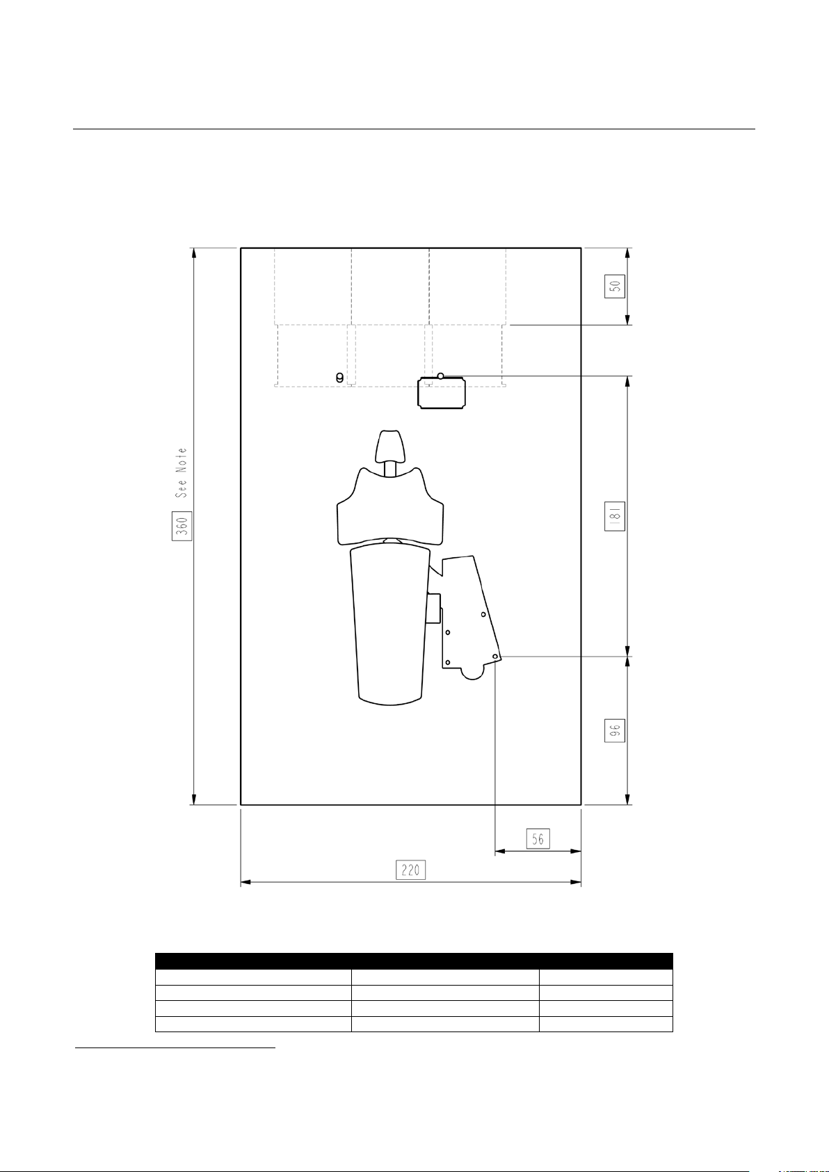
2 INSTALLATION
XO FLEX is intended to be permanently installed in a dental operatory at least 220 cm wide and
1
360 cm long
For transport and storage conditions see Table 1 and in Table 2 the installation requirements are
given.
– see Figure 1 and see the required operation conditions in Table 1.
1
Note: This dimension depends on the depth of the cabinets – in the example shown in Figure 1 the cabinets are 50 cm deep
Figure 1 – Plan of installation – XO FLEX
Table 1 – Operating and transport/storage conditions
8
Page 9
XO FLEX – Instructions for use Installation
Electrical
Requirement
Length above
Mains supply
230 VAC + 10%, 50 – 60 Hz with earth min. 3 x 1,5 mm2
75 cm
Equipotential earth (if
1 x 4.0 mm2
Assistant call control
Min. 2 x 0.1 mm2 and max. 2 x 1.25 mm2
75 cm
X-ray unit attached to the
Cable for X-Ray must have its own installations pipe. Cable shall be connected to an
Suction motor control
Min. 2 x 0.1 mm2 and max. 2 x 1.25 mm2
75 cm
Positioning of cables in
See installation drawing YB-235.
Data
Requirement
Length above
Isolation transformer
When connecting the external PC to the unit, the external PC must be equipped with
RS-232 cable
Connect unit and external PC through a RS-232 cable, male/female. The cable’s
70 cm
XO HD Display
Connect XO HD Display and an external PC through a HDMI cable.
10 cm
Intraoral video camera
Connect the intraoral video camera to an external PC through a USB A cable
USB extension
Suction, air and water
Requirement
Height above
Suction
Suction machine power >600 l/min.
Incoming (compressed)
Pipe 3/8” female internal thread – preferably fitted with a ball valve – see YB-235.
7 cm max.
Incoming water
Pipe 3/8” female internal thread – preferably fitted with a ball valve – see YB-235
7 cm max.
Backflow prevention
If the unit is not supplied with “unit backflow water prevention” it must have an
Drain
Plastic pipe Ø 32 mm with socket – see YB-235.
6 cm max.
Table 2 – Installation requirements
floor surface
Main fuse 10 A
required by national law)
cable
XO unit
cable
the floor
Max. 2 A / 60 VDC or 2 A / 25 VAC
installation box in the floor.
Max. 2 A / 60 VDC or 2 A / 25 VAC
a medical grade power supply or be powered via a medical grade isolating
transformer! XO part number: XO-620
male connector to the unit end.
Depending on the environment it might be necessary to use an HDMI amplifier with
the HDMI cable.
male/female. The cable’s female connector is in the unit end.
It is recommended to use a USB Extension 10 m cable with Repeater from Dürr
Dental - part number: 2106-155-60.
Vacuum pressure at the connection point under static conditions: Min = 35 mbar,
Max = 150 mbar.
Plastic pipe Ø 32 mm with socket – see YB-235.
floor surface
cable: 20 cm
floor surface
6 cm max.
air
Incoming air:
• Air pressure 5.5 – 7,5 bar
• Air flow rate > 55 l/min
• Humidity dew point < -20°C at atmospheric pressure
• Oil contamination max. 0.5 mg/m
• Particulate contamination < 100 particles/m
If the incoming air pressure exceeds 7,5 bar a reduction valve must be fitted.
Air quality must be in accordance to local quality of air regulations.
Incoming water:
• Inlet pressure 2.5 – 6 bar
• Water flow rate > 5 l/min
• Water hardness < 2.14 mmol/l (< 12
In case of poorer water quality, water softener should be replaced more often than
the normal recommendation, for example twice a year
• pH: 6.5 – 8.5
• Maximum particle size < 100µm
If the incoming water pressure exceeds 6 bar a reduction valve must be mounted
before the unit.
Water quality must be in accordance to local drinking water regulations.
external backflow prevention device at the connection point with the water supply,
or an air gab of at least 20 mm.
Gradient of waste water lines > 1%
Drainage capacity > 10 l/min
3
3
(particle size 1 – 5 µm
o
dH)
9
Page 10
XO FLEX – Instructions for use Installation
XO FLEX unit must be installed by an XO authorized service provider.
WARNING: To avoid the risk of electric shock, this equipment must be connected to a
When connecting an external PC (including monitor) to the XO FLEX unit, the
Installation instructions for XO FLEX can be downloaded from xo-care.com.
Authorized service providers are listed under “Distributors” at xo-care.com.
supply mains with protective earth.
external equipment must be powered by a medical grade isolating transformer (e.g.
XO part number: XO-620).
The external equipment must also comply with the applicable standards, e.g.:
• IEC 60950-1 (information technology equipment) or IEC 62368-1 (electronic
equipment within the field of audio, video, information and communication
technology), and
• IEC 60601-1 (medical electrical equipment)
When external equipment is connected to the XO FLEX unit to create a medical
electrical system, the requirements of IEC 60601-1, 3
with.
It is the responsibility of the person/organization installing and/or modifying the
equipment to ensure that the system conforms to applicable legislation, e.g.
Directive 93/42/EEC, or Regulation (EU) 2017/745, and the requirements of IEC
60601-1, 3
rd
edition.
rd
edition, must be complied
10
Page 11
XO FLEX – Instructions for use Operation
A complete technical description of XO FLEX is available at xo-care.com.
3 OPERATION
3.1 GENERAL
XO FLEX is a combined dental unit and patient chair which is to be used by skilled dental
operators for prevention and treatment of diseases in the oral cavity of humans.
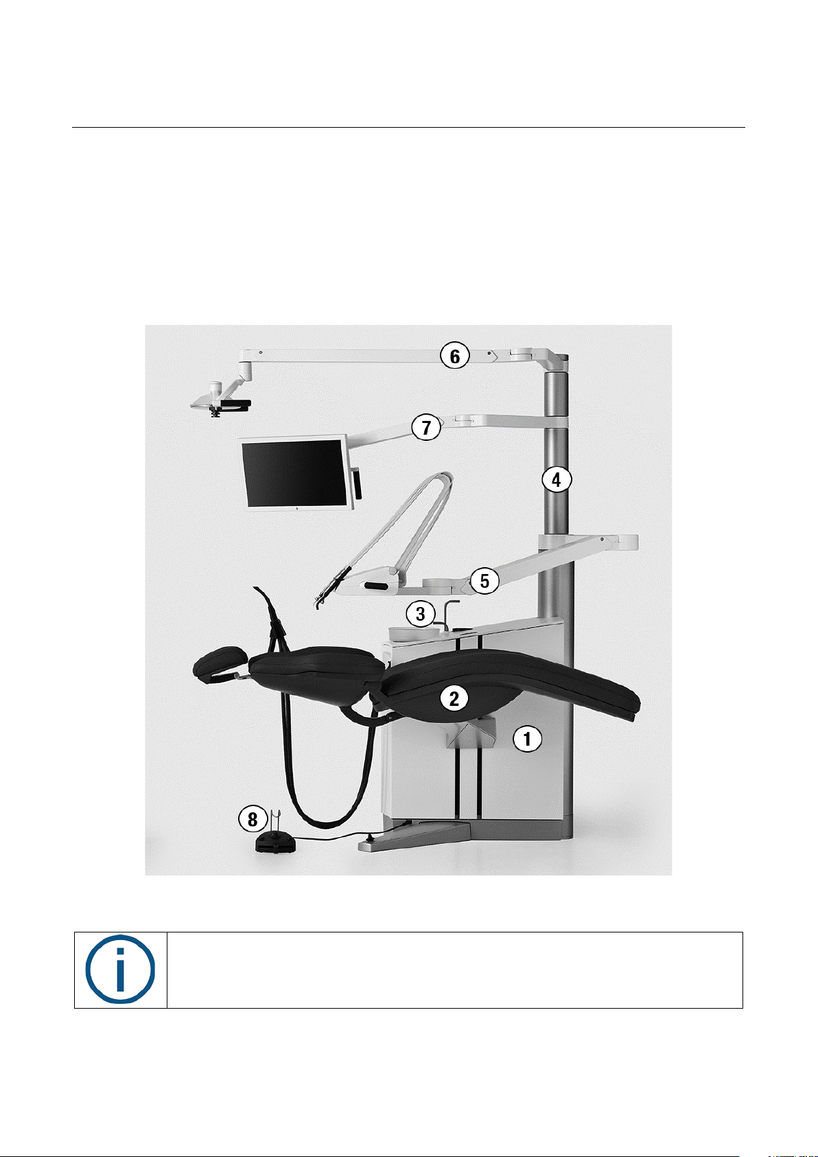
The unit has a compact floor-mounted stand fitted with a patient chair, a cuspidor and singlecolumn pivoting articulated balanced arms for the instrument bridge, operating light and display –
see Figure 2.
Figure 2 – Main XO FLEX elements: (1) unit stand, (2) patient chair, (3) cuspidor and cup filler,
(4) unit column, (5) instrument bridge, (6) operating light, (7) HD Display and (8) foot control
11
Page 12
XO FLEX – Instructions for use Operation
Please note that XO FLEX must be operated in accordance with this manual and by
To avoid injury to persons or material, do not use XO FLEX or its accessories if signs
Do not use XO FLEX in oxygen-rich environments!
Use of other equipment adjacent to or stacked on this equipment should be avoided
Do not simultaneously touch the patient and any external electrical equipment such
Do not simultaneously touch the patient and the connector for peristaltic pump on
dental professionals only!
of operational, electrical or mechanical defects are found.
This equipment does not have a gas sealed electronic enclosure and could ignite any
flammable or explosive gases in its environment.
because it could result in improper operation.
as PCs, monitors, etc.
the rear panel of the unit.
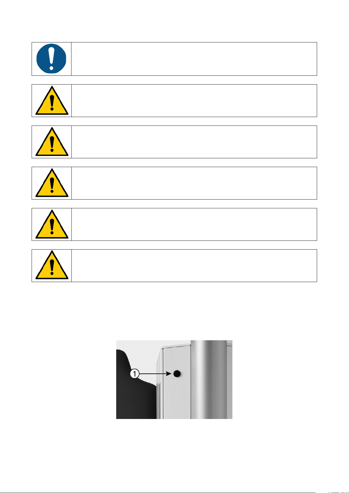
3.2 SWITCH THE UNIT ON
Switch the unit on (and off) using the main switch – see Figure 3.
The unit is ready for use after a few seconds when the text “XO FLEX” is shown on the instrument
bridge display and you hear the welcome tune.
Figure 3 – Main switch (1)
12
Page 13
XO FLEX – Instructions for use Operation
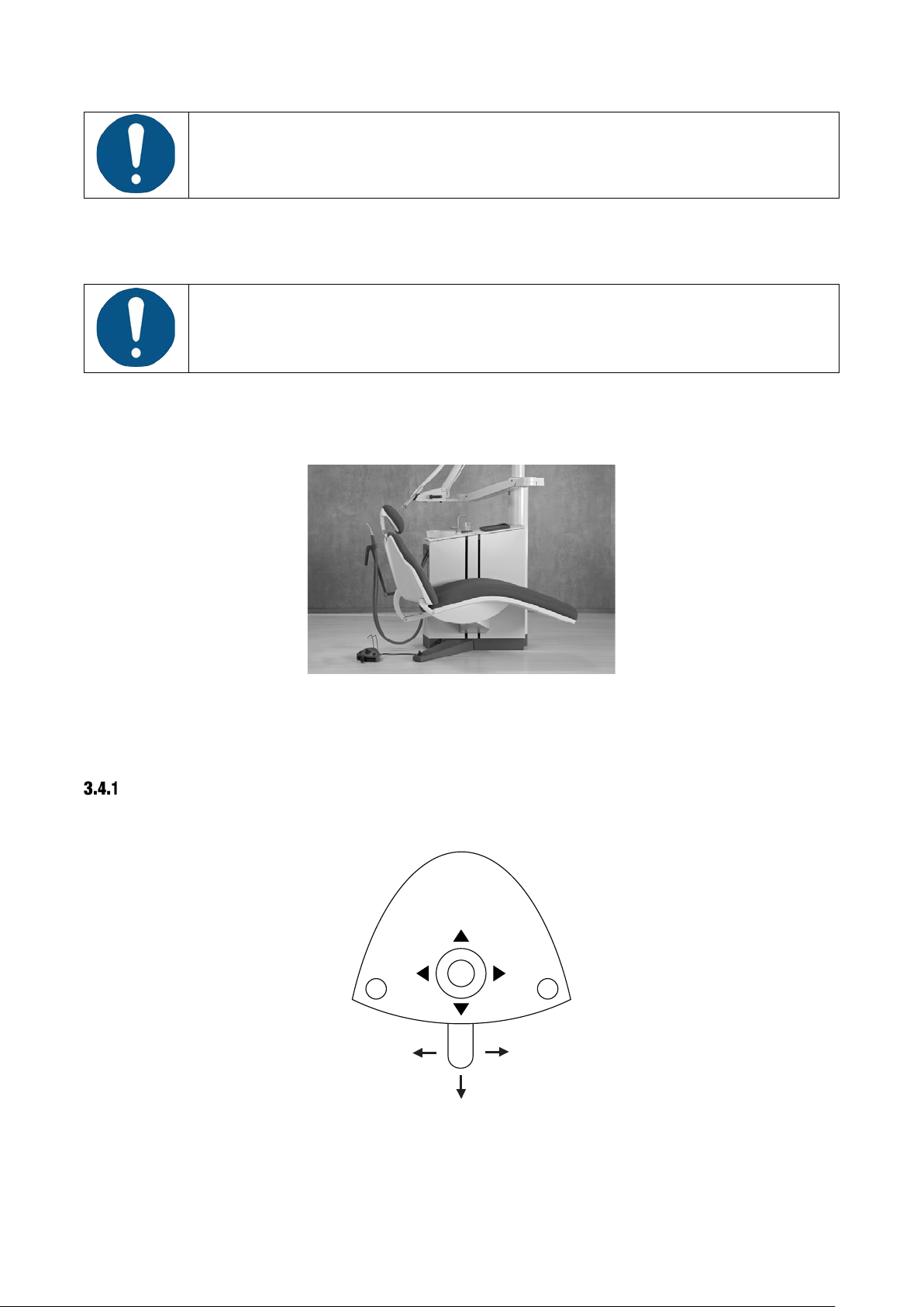
In case of emergency, use this switch to turn off the unit.
Always place the instrument bridge to the left of the unit when the patient is
X
O
3.3 INSTRUMENT BRIDGE IN PARKING POSITION
accessing the chair as shown in Figure 4.
In this position, the patient does not see the instruments when getting in and out of the chair and
the bridge will be easily accessible for cleaning and disinfection.
Figure 4 – Position of instrument bridge for optimal patient access to chair
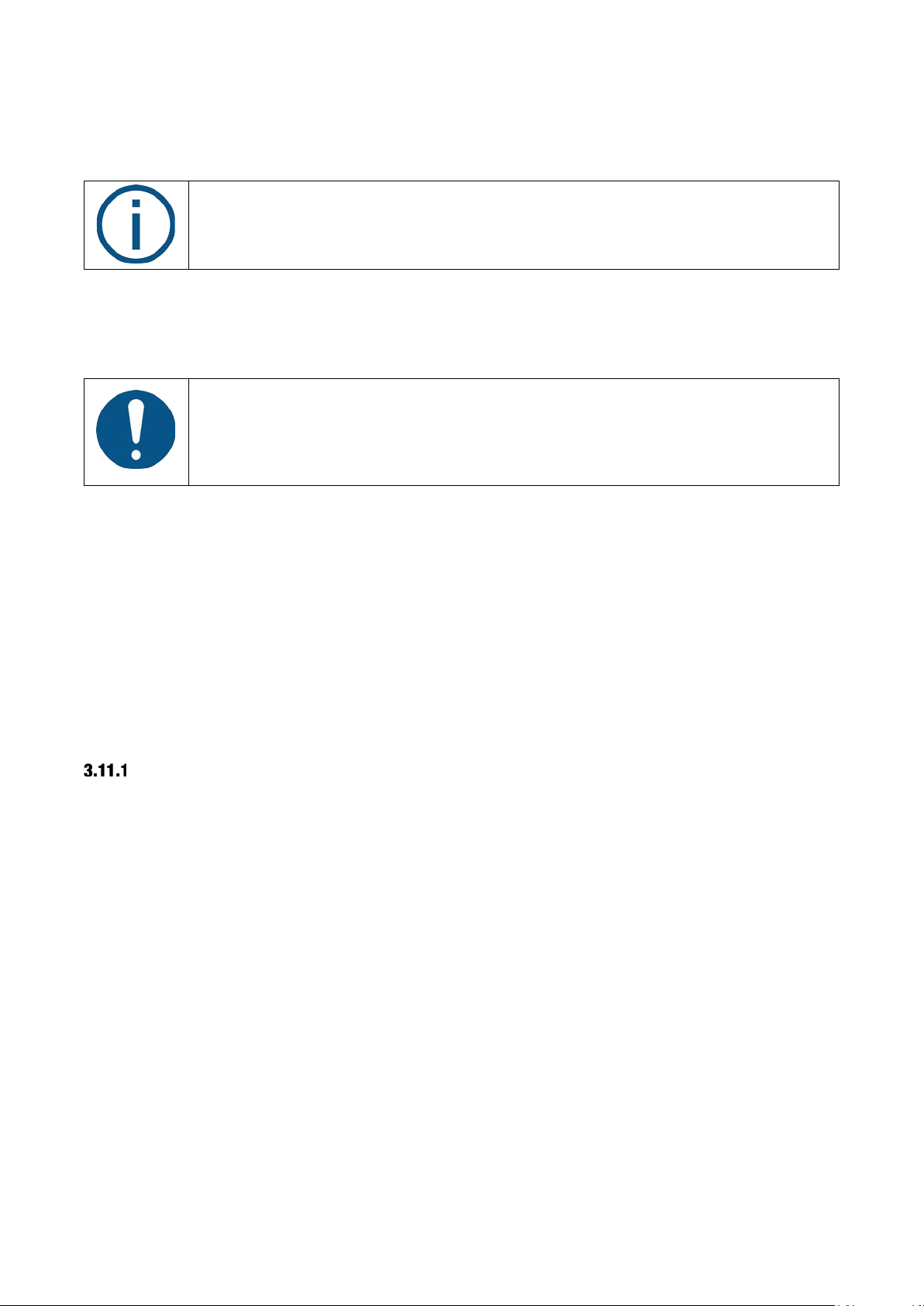
3.4 FOOT CONTROL
FUNCTION
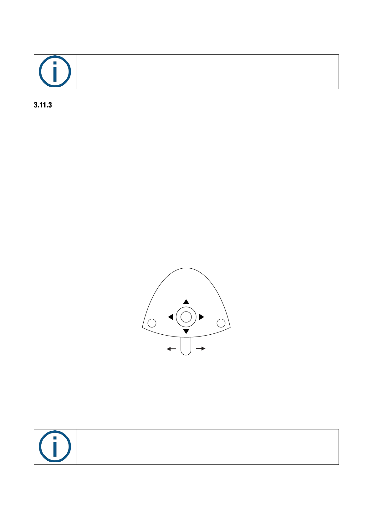
XO FLEX is controlled hands free by using the foot control – see Figure 5 – and the chair base
joystick – see Figure 6.
Figure 5 – Foot control
The foot control has:
• a pedal that can be moved to the right (⮕), to the left (⬅) and pressed down (⬇)
13
Page 14
XO FLEX – Instructions for use Operation
In this manual, the above-presented terminology (e.g. ▲ = move joystick to north) will
See section 14 for an overview of the foot control and chair base joystick functions.
• an X button
• an O button
• a joystick that can be moved north (▲), west (◄), south (▼) and east (►)
When all unit instruments are at rest, the foot control manages functions related to the unit and
chair etc.
When a unit instrument is lifted forward, the foot control manages the active instrument.
The chair base joystick is used to position the patient chair.
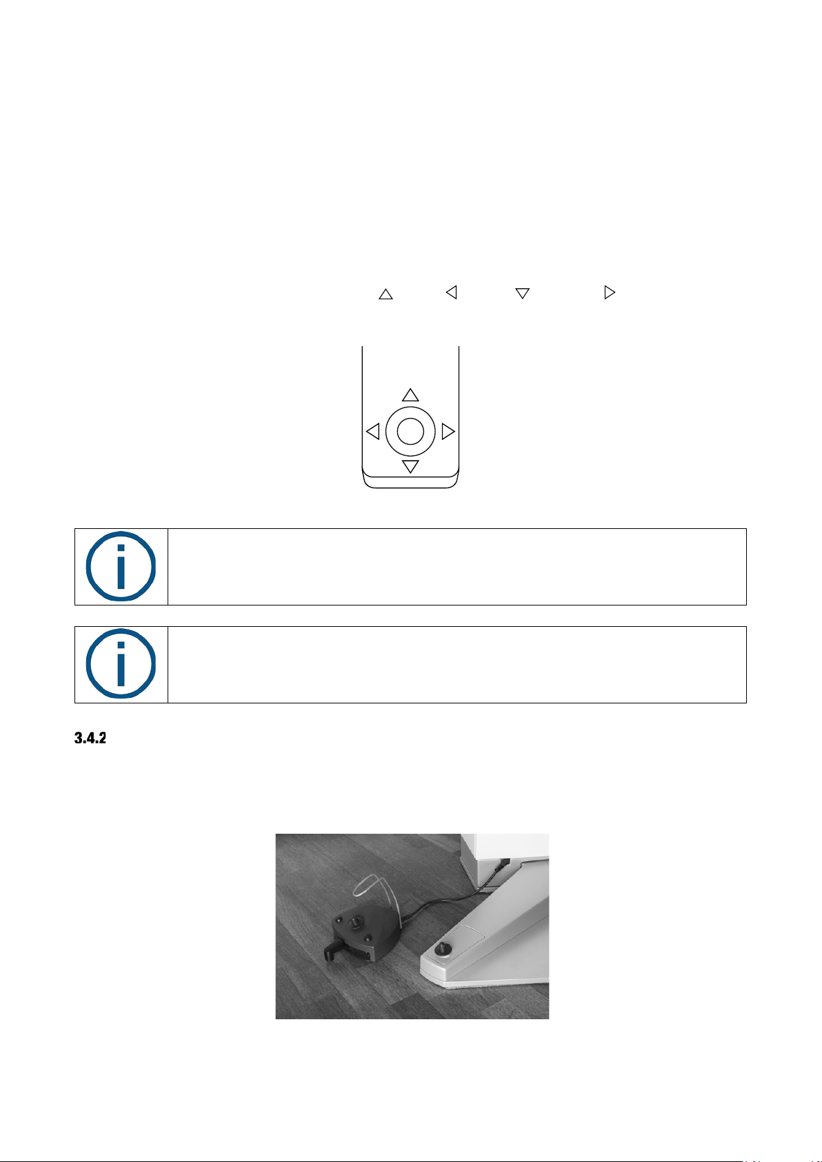
The chair base joystick can be moved north ( ), west ( ), south ( ) and east ( ) – see Figure 6.
Figure 6 – Chair base joystick
be used to explain the functions of XO FLEX.
POSITION THE FOOT CONTROL
Place the foot control close to the unit’s supporting leg and operate it with your right foot when
working in positions 9 – 11 o’clock (see Figure 7). In working position 12 o’clock you may find it
easier to use the left foot (right-handed operator).
Figure 7 – Optimal position of foot control
14
Page 15
XO FLEX – Instructions for use Operation
3.5 XO SMART LINK
XO SMART LINK is an optional software running on an external PC connected to FLEX.
With XO SMART LINK you can configure the function of the foot control and you can work with
instrument programs.
Please see “XO SMART LINK instructions for use”.
3.6 PATIENT CHAIR
FOOT CONTROL OF PATIENT CHAIR
Use the foot control to position the patient chair.
Position the chair in working position 1 with .
Position the chair in working position 2 with .
When you activate the chair moves to the entry position – the position used to enter the chair
and for rinsing.
Activating brings the chair to the previous position – the last “still” position prior to the present.
See Figure 8.
Figure 8 – Position the patient chair using the chair base joystick
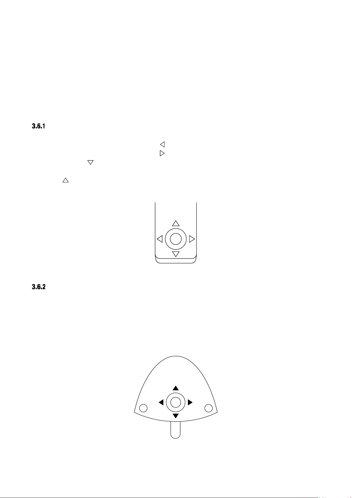
SMALLER ADJUSTMENTS OF PATIENT CHAIR
You make smaller adjustments of the chair with the foot control joystick:
• Lift the chair with ▲ (north)
• Lower the chair with ▼ (south)
• Increase the backrest inclination with ►(east)
• Decrease the backrest inclination with ◄ (west)
See Figure 9.
Figure 9 – Smaller adjustments of the patient chair using the foot control joystick
15
Page 16
XO FLEX – Instructions for use Operation
The patient chair is equipped with a function stop:
To avoid damage never place any objects, including operators’ seats, under the
The patient chair is dimensioned to carry a patient with a weight of up to 150 kg!
XO FLEX is intended to be used primarily with supine patients!
SAFETY
The chair has been designed with a hinged backrest and is shaped so that the legs of the
operators will not be trapped below the chair when moving downwards.
You interrupt all automatic chair movements immediately by touching any button on
the foot control or by lifting an instrument forward.
patient chair.
Exceeding the maximum allowed weight will compromise the structural stability of
the unit and the patient chair.
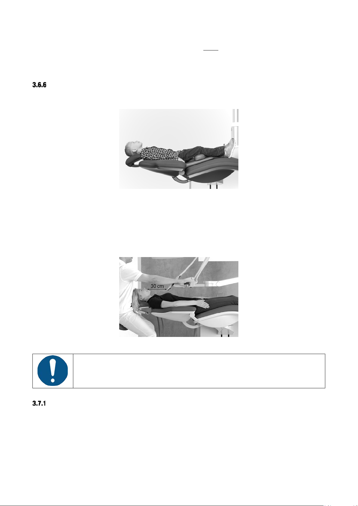
SUPINE PATIENT POSITION
The unit is designed with over-the-patient delivery of instruments for working primarily on supine
patients. That allows you to see all tooth surfaces in good working postures – see details in section
3.7.
NECK REST
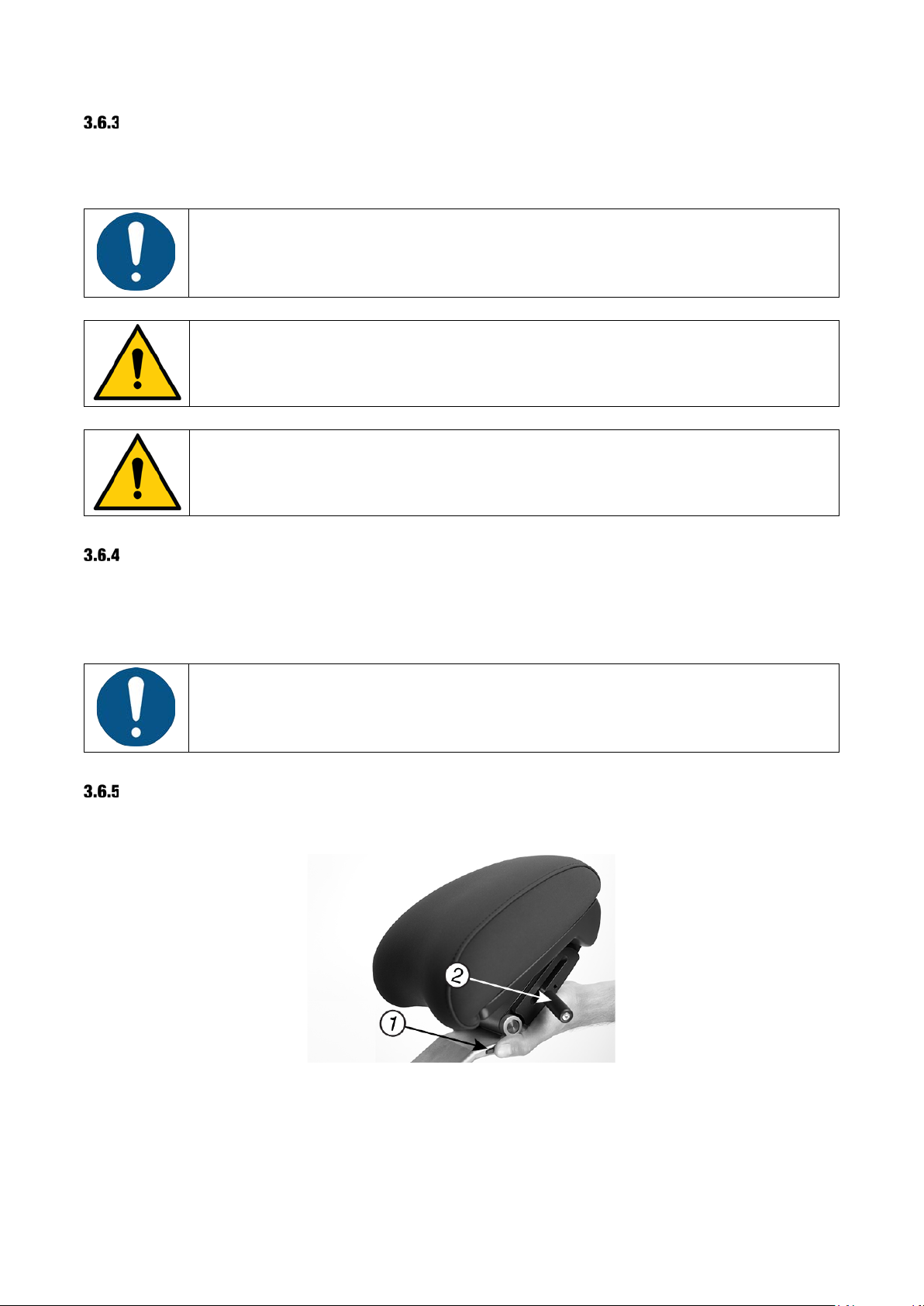
The patient chair is equipped with an adjustable neck rest, supporting the patient’s neck and head.
Figure 10 – Neck rest with (1) longitudinal lock and (2) release handle
To obtain the best patient experience, please follow these instructions when bringing the patient
into a working position:
1. Start positioning the chair
16
Page 17
XO FLEX – Instructions for use Operation
Always use the handles to position the instrument bridge.
2. Release the longitudinal lock (1) – see Figure 10
– while the chair is moving
3. When in the desired working position, adjust the angular position of the neck rest using the
release handle (2)
CHILD CUSHION
For treatment of children, a child cushion is available.
Figure 11 – Child cushion
3.7 INSTRUMENT BRIDGE IN WORKING POSITION
To obtain easy access to and optimal balancing of the instruments, place the instrument bridge
close to the center of the patient’s chest – with a distance from the tips of the instruments to the
oral cavity of 30 cm – see Figure 12.
Figure 12 – Position of instrument bridge while working
Never pull the instrument bridge using an instrument – this may damage the
instrument suspension.
BALANCED INSTRUMENTS
Grab an instrument as shown in Figure 13.
17
Page 18
XO FLEX – Instructions for use Operation
Figure 13 – Lifting an instrument forward
Each instrument suspension is fitted with a spring that can be adjusted so that the instrument is
perfectly balanced - see section 8.4.
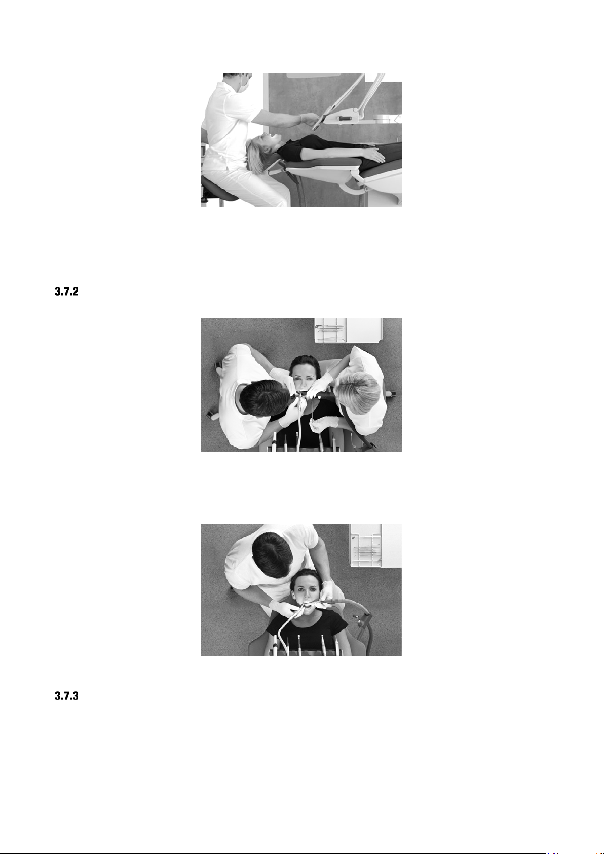
FOUR-HANDED OR SOLO WORK
Figure 14 – Four-handed operation – here the operator is working in the 9 o’clock position, the chairside
assistant in the 3 o’clock position and the hand instruments are positioned near the patient’s temple
XO FLEX is equally suited for four-handed (Figure 14) and two-handed operation (Figure 15).
Figure 15 – Two-handed operation – here the operator is working in the 11 o’clock position
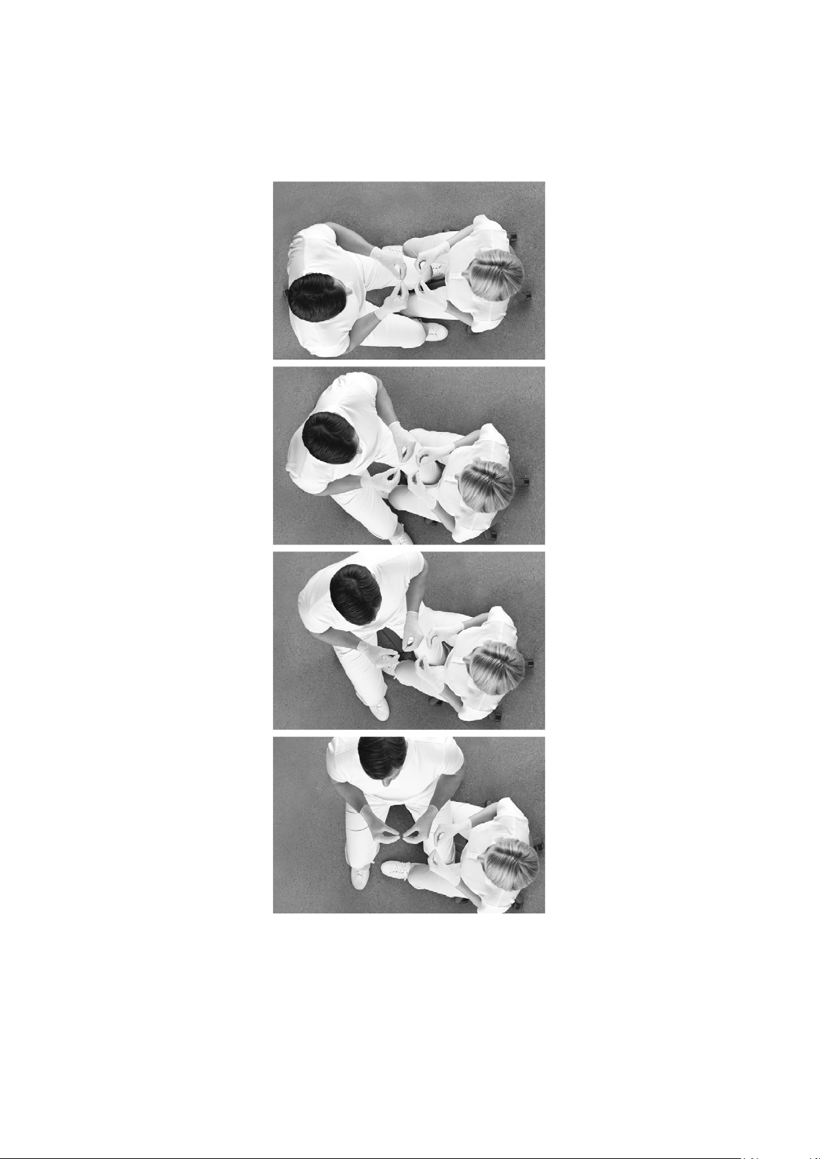
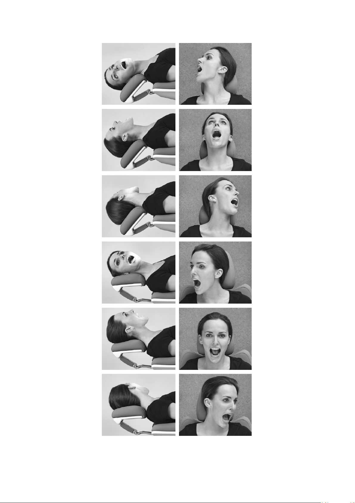
WORKING POSITIONS
With the patient in the supine position you may work in positions between 9 o’clock to 12 o’clock
(see Figure 16) to obtain the best possible vision while maintaining a healthy sitting position (see
section 3.24.)
The patient chair neck rest allows you to place the patient’s head in six different positions (see
18
Page 19
XO FLEX – Instructions for use Operation
Figure 17). This, combined with the flexibility of working in positions between 9 and 12 o’clock (see
Figure 16), provides you with the best possible view of each tooth surface without bending or
straining your neck, spine or upper body.
Figure 16 – Four operator’s positions
19
Page 20
XO FLEX – Instructions for use Operation
Figure 17 – Six different patient positions
20
Page 21
XO FLEX – Instructions for use Operation
3.8 INSTRUMENT CONTROL
FOOT CONTROL OF INSTRUMENTS
You activate the first instrument lifted forward with the foot control pedal. To avoid unintentional
activation of a second instrument lifted forward you will only be able to activate the second
instrument when the first instrument is laid back and the foot control has been released.
The syringe may be used even though another instrument is lifted forward.
The intraoral video camera may be used simultaneously with another activated instrument – but
control of camera functions via the foot control is only possible when the video camera is the only
instrument lifted forward.
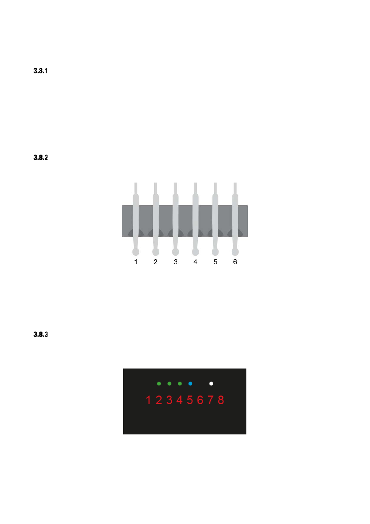
INSTRUMENTS ON THE INSTRUMENT BRIDGE
Up to 6 instruments may be fitted to the instrument bridge.
Figure 18 – Numbering of unit instruments
The instruments are numbered 1 – 6 starting from the left.
Your XO authorized service provider may add instruments or change the order of the instruments –
the multifunction syringe, however, must always be placed to the left (right-handed operator) or to
the right (left-handed operator).
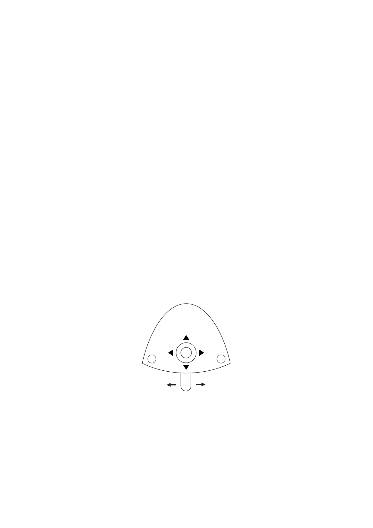
INSTRUMENT BRIDGE DISPLAY
Data concerning the selected instrument is shown on the instrument bridge display – see Figure 19
– and the instrument may be controlled using the foot control.
Figure 19 – Instrument bridge display
21
Page 22
XO FLEX – Instructions for use Operation
X
O
The display consists of:
• One red 8-digit text field mostly used for indication of the primary instrument parameter (for
example, speed of a micro motor)
• Three green LEDs for indication of selected amount (three levels) of spray water or for spray
water off (all LEDs off)
• One blue LED for indication of spray air on/off
• One white LED for indication of automatic chip blow enabled/disabled
3.9 SYRINGE – LUZZANI
The syringe is used as described in the manual supplied by Luzzani – or visit luzzani.com.
Lift the syringe forward and control it with the two buttons.
The syringe can be used at the same time as the other instruments.
3.10 MICROMOTOR – BIEN-AIR MC3 / BIEN-AIR MX2
The micromotor is used as described in the manual supplied by Bien-Air – or visit bienair.com.
The micromotor is intended to be used with contra-angles and handpieces with couplings as
specified in ISO 3964, type 2 or type 3
Lift the micromotor forward and control it with the foot control.
Activate the motor clockwise in the range 100 RPM – select maximum speed
2
(see below) with ⮕
or counterclockwise with ⬅.
Figure 20 – Foot control of micromotor
See the maximum speed on the display when the foot control is not activated.
See the actual speed on the display when the motor is running.
Change spray selection (water & air, air only or no spray) with X.
2
Please note that this is the speed of the micro motor itself. When you fit a contra-angle the speed of the bur may be changed!
22
Page 23
XO FLEX – Instructions for use Operation
When the automatic chip blow is enabled a short burst of high-pressure air dries the
To avoid necrosis, it is generally recommended to work with a “wet” spray that gives
Enable/disable automatic chip blow with O.
preparation each time an instrument with spray water stops.
Using the automatic chip blow function significantly reduces the number of shifts
between rotation instrument and syringe.
Choose between three levels of spray water:
Increase amount of water with ►.
Decrease amount of water with ◄.
at least 50 ml spray water per minute measured with the contra-angle fitted!
In some cases – e.g. when preparing a cavity that is not close to the pulp – and you
want to minimize the spray aerosol – it may be acceptable to use less water in the
spray.
Choose between three maximum speed levels:
Increase maximum speed with ▲.
Decrease maximum speed with ▼.
3.11 XO OSSEO MOTOR
XO OSSEO motor is intended for bone surgery in general and for dental implantology.
XO OSSEO motor is intended to be used with surgical contra-angles and handpieces with
couplings as specified in ISO 3964, type 1.
SET-UP
Appropriate sterile handling procedures must be observed to ensure and maintain sterile
conditions:
1. Remove the sterilized motor and hose from the autoclave bag – or wrap motor and hose
immediately before use.
2. Connect the motor hose to the matching connector at the rear of the instrument bridge –
see section 5.8. The instrument suspension shall be configured as MOTOR.
3. Prepare the peristaltic pump as described in section 3.16.
4. Remove the sterilized contra-angle from the autoclave bag just prior to surgery.
5. Slide the contra-angle firmly in place on the motor shaft.
6. Attach the sterile irrigation tube to the contra-angle using one of the two supplied outlets –
See Figure 21. The choice of outlet depends on the contra-angle.
23
Page 24

XO FLEX – Instructions for use Operation
To avoid necrosis, it is generally recommended to work with an amount of irrigation
X
Figure 21 Attaching the irrigation tube
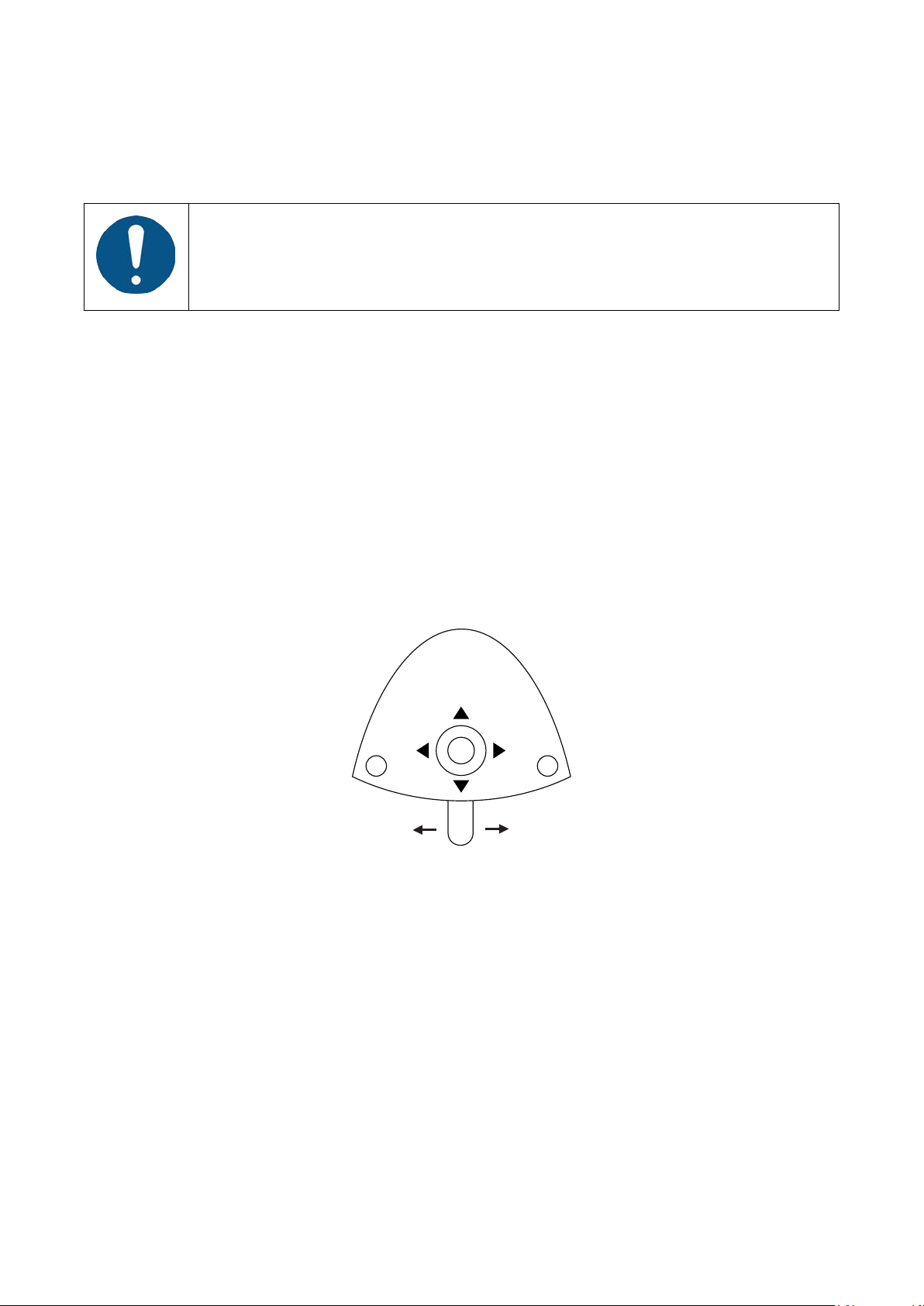
OPERATION
Lift the motor forward and control it with the foot control.
Activate the motor clockwise in the range 100 RPM – select maximum speed
3
(see below) with ⮕
or counterclockwise with ⬅.
See the maximum speed on the display when the foot control is not activated. See the actual
speed on the display when the motor is running.
Figure 22 – Foot control of XO OSSEO motor
Switch irrigation on/off with X.
Choose between three levels of irrigation:
Increase amount of irrigation with ►.
Decrease amount of irrigation with ◄.
of at least 50 ml per minute measured with the contra-angle fitted!
Choose between three maximum speed levels:
Increase maximum speed with ▲.
Decrease maximum speed with ▼.
3
Please note that this is the speed of the motor itself. When you fit a contra-angle the speed of the bur may be changed!
24
Page 25
XO FLEX – Instructions for use Operation
The motor operates at maximum torque.
When the automatic chip blow is enabled a short burst of high-pressure air dries the
X
O
Please see section 3.11.3 if you need to control the maximum torque!
IMPLANT SURGERY - OPERATION WITH XO SMART LINK
In combination with XO Smart Link you can work with instrument programs and implant
treatments.
Please see “XO Smart Link – Instructions for use”.
3.12 AIR INSTRUMENT
An air turbine or an air scaler may be attached to the hose – in the following called “the air
instrument”.
The air instrument is used as described by the supplier.
Air instruments with a type 3 coupling as specified in ISO 9168 shall be used.
Lift the air instrument forward and control it with the foot control.
Activate the air instrument (one step) with ⮕ or ⬅.
Figure 23 – Foot control of turbine
See drive air (in % of maximum) on the display.
Change spray selection (water & air, air only or no spray) with X.
Enable/disable automatic chip blow with O.
preparation each time an instrument with spray water stops.
Using the automatic chip blow function significantly reduces the number of shifts
between rotation instrument and syringe.
25
Page 26
XO FLEX – Instructions for use Operation
To avoid necrosis, it is generally recommended to work with a “wet” spray that gives
X
Choose between three levels of spray water:
Increase amount of water with ►.
Decrease amount of water with ◄.
at least 50 ml spray water per minute measured with the turbine hand-piece fitted!
In some cases – e.g. when preparing a cavity that is not close to the pulp – and you
want to minimize the spray aerosol – it may be acceptable to use less water in the
spray.
Choose between three drive air levels:
Increase drive air with ▲.
Decrease drive air with ▼.
3.13 ULTRASONIC SCALERS
The ultrasonic scaler is used as described by the supplier.
For XO ODONTOSON scalers see below in section 3.14.
Lift the scaler forward and control it with the foot control.
Switch on the power (one step) with ⮕ or ⬅.
Figure 24 – Foot control of scaler
See the power (in % of maximum) on the display.
Enable/disable irrigation water with X.
Choose between three levels of irrigation water:
Increase amount of water with ►.
Decrease amount of water with ◄.
Choose between three power levels:
• Increase maximum power with ▲.
• Decrease maximum power with ▼.
For details about XO ODONTOSON 360 scaler see below.
26
Page 27
XO FLEX – Instructions for use Operation
For Thin Line instruments please observe:
For details about other scalers – see user manuals supplied by the manufacturer.
3.14 XO ODONTOSON 360 ULTRASONIC SCALER
XO ODONTOSON 360 is intended to be used for treatment in the oral cavity of humans. XO
ODONTOSON 360 is a multi-purpose dental scaler for periodontology, endodontics and
prophylaxis.
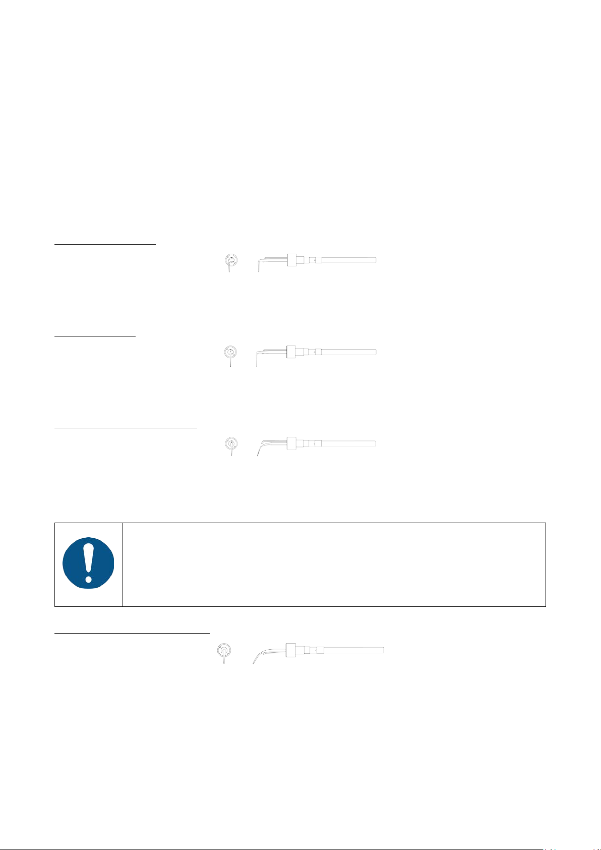
XO ODONTOSON 360 is supplied with one handpiece and six instruments (consisting of a titanium
tip fitted with an exchangeable ferrite rod) fitted into two autoclavable instrument holders in Teflon:
Universal instrument (209080) – 2 pieces
For removal of supra- and subgingival stain and calculus in all areas and for general scaling on
patients with moderate plaque or calculus.
Perio instrument (209030)
Removes supra- and subgingival stain and calculus in all areas. Particularly useful for removal of
subgingival calculus in pockets as deep as 13 mm. Use the tip as if using a periodontal probe.
Thin Line Straight instrument (209034) – 2 pieces
Useful for fine planning after gross scaling with other XO ODONTOSON 360 instruments. Provides
good furcation access. Is also useful for root planning, but only after gross debridement with a
Perio instrument.
Use only for fine scaling or debridement after gross scaling with other instruments.
Repeated use of Thin Line instruments for gross scaling can result in damage to the
titanium tip.
Thin Line instruments should never be used at power level settings more than 50 %
of maximum power.
Heavy Duty Straight Instrument (209010)
Particularly useful for removal of supra- and subgingival calculus labially and lingually. Can be
applied interproximally, using the rounded tip to remove calculus and other heavy deposits and
stains.
27
Page 28
XO FLEX – Instructions for use Operation
Do not attempt to sharpen, bend or otherwise re-shape the instrument tips!
When working with XO ODONTOSON 360:
Increasing the contact pressure will neither increase the efficiency nor improve the
Doing so may seriously degrade the performance of the instrument.
For a complete list of available instruments – including instruments for endo procedures – please
visit xo-care.com.
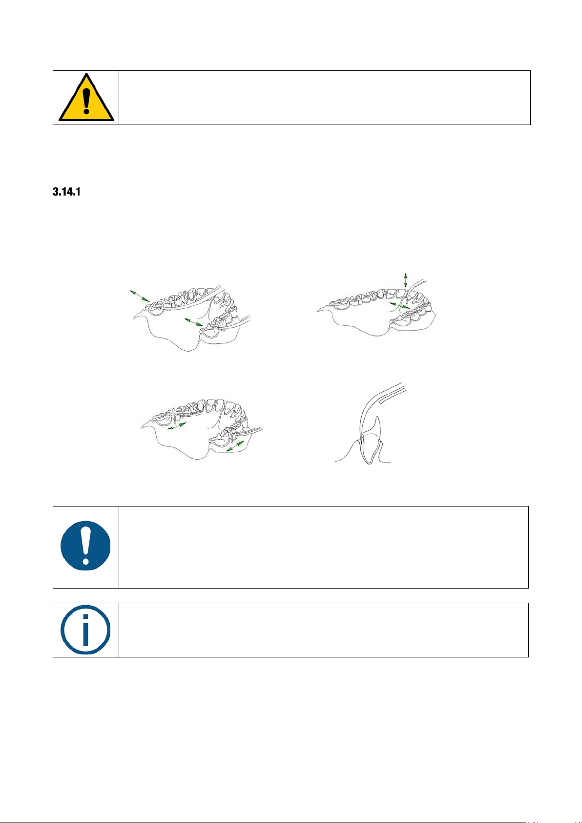
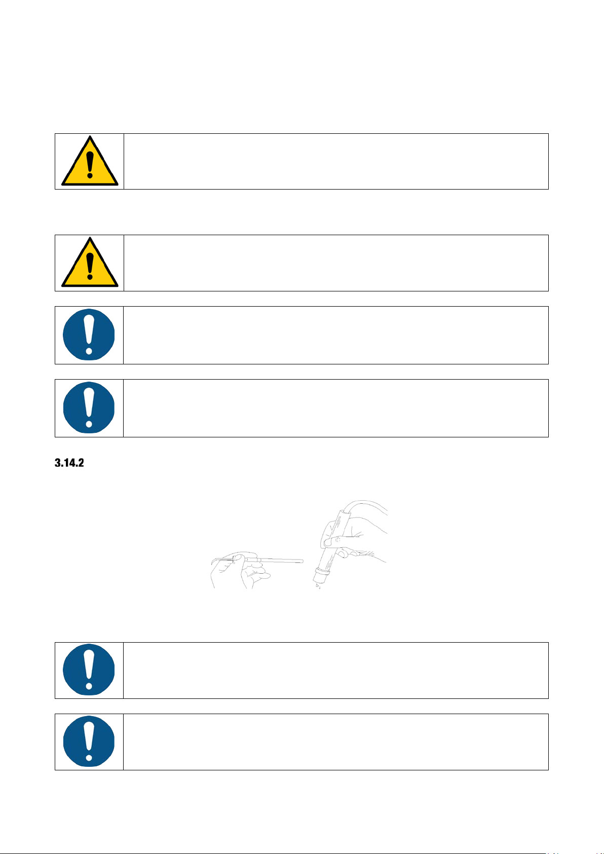
HOW TO USE XO ODONTOSON 360
To fully benefit from the rotational titanium tip movement and high frequency, it is important that
the instrument is properly handled and applied – see Figure 25.
Use short, sweeping, paintbrush-like, back and forth strokes over the surface being treated.
Keep the tip moving back and forth with the end of the tip probing the pocket when necessary.
Figure 25 – Using XO ODONTOSON 360
• Always use the instrument parallel to the tooth surface with the sides of the
tip applied to the tooth surface
• Do not apply the tip at right angles to the tooth surface
• Do not use the tip as a pick – this will scratch the tooth surface
• Always apply very little pressure to the tooth surface
quality or speed of the treatment!
If you use XO ODONTOSON 360 instrument in this way you will achieve:
• Easy access to any tooth surface without awkward positioning of the hand-piece and hand.
As the tip rotates and is "active" on all sides, you have a 360° highly efficient working
surface without “dead zones”.
28
Page 29
XO FLEX – Instructions for use Operation
Only use XO ODONTOSON 360 on teeth and root surfaces.
Risk of thermal injury!
Handle the instruments carefully as the attached ferrite rod is fragile!
Always use as much irrigation water as practically possible to avoid unnecessary
Always empty the hand-piece of any water before applying a new instrument.
It is important that the instrument is always firmly seated in the hand-piece!
• The rotational motion brushes rather than “hammers” the tooth. This has a gentle polishing
effect on the tooth. It is generally much less painful for the patient and less tiring for the
operator.
Use the mirror to hold lips and tongue away from the instrument tip.
Avoid touching patient lips, tongue or other soft tissue with the non-cooled part of
the instrument tip!
wear of the instrument.
CHANGING THE INSTRUMENT
Detach the instrument from the hand-piece just by pulling it out.
Figure 26 – Changing instrument
Wipe off any drops of water before applying an instrument.
29
Page 30

XO FLEX – Instructions for use Operation
As a matter of course, the titanium tips will become worn down with time due to use. The efficiency
of an instrument will therefore be gradually reduced.
Several factors contribute to wear of instruments:
• Time used
• The type and consistency of calculus deposits in patients
• The quantity of irrigation being used
The lifetime may therefore vary considerably from instrument to instrument.
XO ODONTOSON 360 WITH ANTIMICROBIALS AND STERILE SALINE
In combination with XO Peristaltic Pump, XO ODONTOSON 360 can be used with antimicrobials or
sterile saline.
Prepare the peristaltic pump as described in section 3.16.
Insert the connector piece (XO-069) between the hose and the handpiece – as shown in Figure 27.
Figure 27 – Connector piece for external irrigation of XO ODONTOSON 360
Attach the irrigation tube to the connector piece using the appropriate outlet – see Figure 28.
Figure 28 – XO ODONTOSON 360 connected to external irrigation
3.15 XO ODONTOCURE CURING LIGHT
The intended use of XO ODONTOCURE is polymerization of light cure resin based composites
used for fillings in human teeth.
Lift the curing light forward and control it with the foot control.
See the current exposure time on the display before the foot control is activated.
Choose between three different exposure times with ▲ and ▼ and see the selected time on the
instrument bridge display.
Start the curing process with ⮕ or ⬅.
30
Page 31

XO FLEX – Instructions for use Operation
Never look directly into the light or direct it at the eyes of others!
CAUTION! The high light intensity of XO ODONTOCURE is accompanied by heat
O
Figure 29 – Foot control of XO ODONTOCURE
See elapsed exposure time on the display during the process.
Hear a beep at intervals of 5 seconds.
XO ODONTOCURE emits thermal radiation, and blue light and ultraviolet light in the
range 385 – 515 nm at an intensity that requires protection of the eyes. Protect eyes
with light shield and/or protective eyewear that removes light in the previously
mentioned wavelengths.
generation on the exposed surface! Uninterrupted exposure of more than 20 seconds
to the same surface shall be avoided. Curing at intermitted intervals is
recommended.
Switch soft-start on and off with O while the light is not activated.
Soft-start is a feature that can help reduce shrinkage. When enabled, the light will emit light at a
reduced intensity for a manually preset number of seconds before going to full intensity.
For curing of posterior teeth use a protection cap:
Figure 30 Protection cap
For curing of anterior teeth use the light shield:
31
Page 32

XO FLEX – Instructions for use Operation
XO ODONTOCURE is intended for intermittent use. If activated continuously the
Use of peristaltic pumps requires that the unit be prepared for it (i.e. unit must be
Figure 31 Light Shield
message “TOO HOT” is displayed and the instrument is turned off.
After some seconds, depending on the temperature, the light is ready for reactivation.
3.16 XO PERISTALTIC PUMP
XO Peristaltic Pump is intended for supplying sterile saline or antimicrobials when using XO
ODONTOSON 360 or XO OSSEO motor.
Irrigation liquid is carried by means of the pump and an irrigation tube, from a reservoir or a bag
located at the rear of the unit to an instrument of the operator’s choosing. The irrigation tube is part
of a disposable irrigation kit that contains the different tube parts needed for connecting a reservoir
or bag with the different supported instrument types.
The pump is detachable and can be shared among multiple XO units.
The pump is automatically detected by the unit when attached.
equipped with option XO-051).
DISPOSABLE IRRIGATION KIT
The irrigation kit is manufactured for XO CARE A/S as an accessory for XO Peristaltic Pump.
The kit consists of a main tubing part and two alternative outlet parts. The main tube is equipped
with a bag inlet cannula and an insert piece for the pump. Two alternative outlet parts are provided:
one for connecting hand-pieces with a single inlet and one for connecting hand-pieces with two
inlets.
32
Page 33

XO FLEX – Instructions for use Operation
Risk of contamination!
The disposable irrigation kit package has been sterilized by ethylene oxide gas. Sterility
cannot be relied upon if 1) the package has been opened or damaged or 2) the expiration
date stamped on the package has passed.
Appropriate sterile handling procedures must be observed to ensure and maintain sterile
conditions.
The disposable irrigation kits are for one-time use only. Do not re-sterilize!
XO Peristaltic Pump is delivered with two sample disposable irrigation kits. Additional kits can be
ordered from your XO distributor:
• Pre-sterilized, disposable irrigation kit, 50 pcs (XO-055)
• Pre-sterilized, disposable irrigation kit, 10 pcs (XO-056)
ATTACHING THE PUMP MODULE
Attach the pump module as shown in Figure 32.
After use, the pump module can be safely removed from the unit. It is not necessary to switch off
the unit before detaching the pump.
ATTACHING THE IRRIGATION TUBE
Release the pump head by turning the handle (1) counter-clockwise – see Figure 33.
Attach the irrigation tubing to the pump head as shown in Figure 34.
Make sure the tube is held in place by the two plastic connectors.
Figure 32 – Attaching the pump module to the unit
Figure 33 – Releasing the pump head
33
Page 34

XO FLEX – Instructions for use Operation
Figure 34 – Attaching the irrigation tubing
Lock the pump head by turning the handle (1) clockwise – see Figure 35.
Figure 35 – Locking the pump head
Place the irrigation tube into the tube guide and attach it to the instrument bridge arm, as shown in
Figure 36.
Figure 36 – Placing the irrigation tube
Attach the irrigation tube to the hose of the instrument to be used using the stainless steel clips –
see Figure 37.
34
Page 35

XO FLEX – Instructions for use Operation
Figure 37 – Attaching the irrigation tube to the instrument hose
IRRIGATION BAG
Insert the bag inlet cannula into the irrigation bag and hang the bag containing the irrigation liquid
from the knob at the bottom of the pump module – see Figure 38.
Figure 38 – Irrigation bag
IRRIGATION RESERVOIR
Place the reservoir containing the irrigation liquid into the holder below the pump – see Figure 39.
Figure 39 – Placing the reservoir
Using an appropriate sterile tool (e.g. a pair of scissors), cut the inlet cannula off the irrigation
tubing. Attach the irrigation tubing to the spear and place the spear in the reservoir.
See Figure 40.
35
Page 36

XO FLEX – Instructions for use Operation
Figure 40 - Cutting the irrigation tubing bag inlet cannula
DESIGNATION OF INSTRUMENT
Figure 41 – Initiating selection of instrument to be used with XO Peristaltic Pump
Before the pump can be used, a designated instrument must be selected.
With all instruments at rest, press the button (1) once – see Figure 41.
The unit enters configuration mode and a menu will be shown on the display.
Activate ▲ and ▼ of the foot control joystick to navigate to the menu item labeled “PUMP”.
Figure 42 – Foot control configuration of peristaltic pump
Activate ► to access configuration of the pump – see Figure 43.
36
Page 37

XO FLEX – Instructions for use Operation
Figure 43 – Display
Use ▲ and ▼ to select the designated suspension that should be used with the pump – see
numbers in Figure 18, page 21.
Figure 44 – Displaying instrument suspension
Use ◄ to confirm the choice of suspension.
Press the configuration button (1) on Figure 41 once to exit configuration mode.
When the designated instrument has been selected, the green LED will blink.
If you want to use the designated instrument without peristaltic pump, select “NONE” in the PUMP
menu.
ADJUSTING THE FLOW LEVEL
Choose between three levels of irrigation:
Increase irrigation with ►
Decrease irrigation with ◄
3.17 INTRAORAL HD VIDEO CAMERA
Unlike all other unit instruments, you may use the video camera also when another instrument is
active.
Lift the camera forward and display a video image on a screen.
Control the video camera with the foot control when no other instruments are lifted forward.
Toggle between “still” and “live” mode with ⬅.
Save the active video image to the connected PC with ⮕.
37
Page 38

XO FLEX – Instructions for use Operation
The intraoral camera must be connected to an external PC!
To use the foot control for controlling the camera, the PC must be appropriately
To ensure a stable connection, we highly recommend that the connection be made
Place the light head 70 cm from the patient’s lips and position the light head so that
Figure 45 – Foot control of intraoral video camera
This is done during installation of the unit and shall be done by an XO authorized
service provider.
configured and a compatible imaging program must be used. Furthermore, the PC
must be connected to the unit by means of a serial cable for carrying the control
signals from the foot control to the imaging program. This is in addition to the USB
cable carrying the video signal.
Please consult your XO authorized service provider for further details.
using a special USB cable supplied by Dürr Dental.
For other information please see the enclosed information from Dürr Dental.
3.18 OPERATING LIGHT
POSITION THE LIGHT
the direction of the light is parallel to your viewing direction. See Figure 46.
This position of the light head also prevents the instrument suspensions from touching the light
head while working.
38
Page 39

XO FLEX – Instructions for use Operation
Figure 46 – Correct position of light
SWITCH THE LIGHT ON AND ADJUST THE LIGHT INTENSITY
Manage the light manually by activating the no-touch sensor under the light head – see Figure 47
(1).
Hold your hand within activation distance for less than one second and the lamp switches on/off.
Change the light intensity (3 levels) by activating the sensor for more than one second.
Figure 47 – No-touch sensor
Optionally, you may configure the operating light to be switched on/off using the foot control while
the instruments rest:
• Switch the light on/off with a short activation of ⬇
• You change light intensity by holding ⬇ down
Figure 48 – Optional foot control of light
39
Page 40

XO FLEX – Instructions for use Operation
When working with light-curing composites please note that the operating light may
Please note that XO HD Display must be connected to an external PC!
The best image quality is obtained using the native resolution of 1920 * 1080 pixels.
Please do not press the sensor buttons too hard or you may damage the buttons!
MENU AU TO
BUTTON
DESCRIPTION
MENU
Menu Button. Press this button to show the on-screen-display (OSD). This button is also used to exit
influence the curing process.
Switch to a lower light intensity or switch the light off if necessary!
AUTOMATIC FUNCTIONS
The light switches on automatically when the patient chair reaches working positions 1, 2 or
previous position.
The light switches off automatically when the patient chair is moved towards the entry position.
3.19 XO HD DISPLAY
The display contains 6 sensor buttons at the bottom right (see Figure 49). The meanings of the
buttons are described in Table 3. Note that some buttons have different functionality depending on
whether the on-screen-display (OSD) is shown or not.
Figure 49 – Control panel sensor buttons – HD display
Table 3 Control panel sensor buttons – HD display
the OSD or to return to a higher-level OSD menu.
40
Page 41

XO FLEX – Instructions for use Operation
BUTTON
DESCRIPTION
If held pressed for 10 seconds, this button will lock the OSD. When locked, it is not possible to
seconds.
Game mode button (not relevant for dental use).
Up/down buttons. These buttons are used for navigating the menu or to adjust values in the OSD.
Brightness button. This button is used to control the brightness of the display.
Switch input button. Use this button to switch between analogue and digital input.
Select button. Used for selecting functions in the OSD.
AUTO
Auto button. Use this button to automatically adjust the display settings when using an analog input.
ON/OFF button. Switches the display on and off.
automatically be switched on as well.
change the OSD settings. The lock can be disabled by holding the menu button pressed for 10
Note: Switching off the unit will also switch off the display. When the unit is on again, the display will
3.20 HAND INSTRUMENTS
The optimal place for hand-instruments is near the patient’s temple – see Figure 50 – where both
you and your chairside assistant can reach the instruments in healthy postures.
Figure 50 – Hand-instrument table near the patient’s temple
Alternatively, the unit may be configured with a hand-instrument table fitted under the instrument
bridge – see Figure 51.
Figure 51 – Hand-instrument table attached to XO FLEX
41
Page 42

XO FLEX – Instructions for use Operation
Maximum load on hand instrument table attached to XO FLEX unit is 1.5 kg!
Please note that the brake and the balance spring of the arm system should be adjusted by an XO
authorized service provider in accordance with the load of the hand instrument table.
Exceeding the limit may compromise the balance of the instrument bridge and could
cause the bridge suspension arm to fail altogether exposing the patient to a risk.
3.21 SUCTION
Activate each suction hose individually by lifting it from the holder. When working solo, move the
suction hose holder forward to facilitate easy access to the suction hoses.
Figure 52 – Suction – (1) DUO position / (2) SOLO position
Relieve the suction hose by pressing it into the slot in the suction hose holder.
Figure 53 – Relieving the suction hose
3.22 CUSPIDOR AND CUP FILLER
Start the cuspidor flush manually with (1) – see Figure 54 – it will stop automatically after the preset
rinsing time.
Abort the cuspidor flush by activating (1) while rinsing.
42
Page 43

XO FLEX – Instructions for use Operation
X
Figure 54 – Manual start of (1) cuspidor and (2) cup filler
Activate (2) – see Figure 54 – for less than one second and the glass fills with the pre-configured
amount of water.
Activate (2) again for less than one second to stop automatic filling.
If (2) is activated for more than one second, water fills the cup while the button is activated.
The cup filler may alternatively be activated/deactivated using X while all unit instruments rest.
Figure 55 – Foot control of cup filler
AUTOMATIC FUNCTION
The cuspidor flush starts automatically after the cup filler has been activated and when the patient
chair reaches the entry-position.
3.23 ASSISTANT CALL
Activating O while all unit instruments are at rest will activate a relay contact that may be
connected to a bell or other external signaling devices.
43
Page 44

XO FLEX – Instructions for use Operation
Sound
Meaning
Welcome
The unit is turned on and ready to use
Wrong
You try to do something that does not make sense
Setting saved
Setting saved successfully
Notification
A non-urgent event occurred
Connection lost
Computer connection is disconnected
To maintain a healthy sitting position, it is extremely important to individually adjust
O
Figure 56 – Foot control of assistant call
3.24 SOUND GENERATOR AND SOUNDS
The instrument bridge is fitted with a sound generator that indicates events as described below:
Table 4 - Sounds
3.25 SYSTEM MESSAGES
The unit generates messages that can be seen from the instrument bridge display.
See details in section 7.
3.26 XO SEAT AND XO STOOL
We recommend you sit in an upright, balanced position with an angle between thighs and upper
body of about 120
XO SEAT and XO STOOL are available in two heights: 1) for operators up to about 180 cm tall and
2) for operators who are taller. If your XO SEAT/XO STOOL is too low or too high, it is possible to
replace the gas spring with a shorter or longer version. Please contact your XO authorized service
provider.
If the height difference between the operator and the chairside assistant is more than 10 cm, a
foot-ring may be fitted.
o
– see Figure 57.
the height and seat angle of the operator’s stool as described in this section!
44
Page 45

XO FLEX – Instructions for use Operation
Figure 57 – Upright, balanced position
XO SEAT
Adjust the seat height using the left handle as shown in Figure 58.
Figure 58 – Adjustment of seat height
Adjust the seat angle with the right handle as shown in Figure 59.
45
Page 46

XO FLEX – Instructions for use Operation
Figure 59 – Adjusting the seat angle
XO STOOL
Adjust the seat height as shown in Figure 60 and the seat angle as shown in Figure 61.
Figure 60 – Adjusting the seat height
Figure 61 – Adjusting the seat angle
Adjust the backrest as shown in Figure 62 and Figure 63.
46
Page 47

XO FLEX – Instructions for use Operation
Figure 62 – Adjusting the backrest angle
Figure 63 – Adjusting the backrest height
47
Page 48

XO FLEX – Instructions for use Configuration
4 CONFIGURATION
This section describes the many aspects of XO FLEX that can be customized to fit your personal
needs.
4.1 CONFIGURATION OF PATIENT CHAIR POSITIONS
1. Adjust the chair to the required position using the foot control joystick as described in
section 3.6.2
2. Press the configuration button – see Figure 64 – within 8 seconds
3. The display will show “CHAIR”
4. Activate the chair base joystick – see Figure 65 – according to the position being
configured:
: Working position 1
: Working position 2
: Rinse position
(twice within one second): Entry position
5. Subsequently, an “OK” sound is heard
6. The display will show the configured position shortly afterwards
Figure 64 – Configuration button (1) under the instrument bridge
Figure 65 – Chair base joystick
4.2 CONFIGURATION OF GENERAL UNIT AND PATIENT CHAIR FUNCTIONS
1. Activate the configuration button (1) while all instruments are resting – see Figure 64.
2. Activate ▲ / ▼ or ⬇ – see Figure 66 – to browse the parameter to change (see Table 5)
3. Activate ► to select the parameter to change
4. Use ▲ / ▼ to change the value of the selected parameter or ⬇ to increase the value
5. Activate ◄ to save the new value
6. Press the configuration button again
48
Page 49

XO FLEX – Instructions for use Configuration
Parameter
Display text
Factory default
Possible settings
Enabling XO Peristaltic
PUMP
None
None, POS. 1 – 6
Cuspidor flush stops
FLUSH/S
15 s
10 – 600
Cup filler stops after
CUP/S
10 s
5 – 15 s
Cuspidor flush starts
FLUSH/CH
Enabled
Disabled, enabled
Cuspidor flush starts
FLUSH/CF
Enabled
Disabled, enabled
Light on when patient
LAMP/CH
Disabled
Disabled, enabled
Light on/off with foot
LAMP/PD
Disabled
Disabled, enabled
Reset unit and patient
RESET
-
Yes, No
Rinse position = entry
RINSE = 0
Disabled
Disabled, enabled
Figure 66 – Configuration using the foot control
Table 5 – Unit and patient chair parameters that can be configured
configuration
Pump
after
automatically when chair
reaches entry position
automatically when cup
filler stops
chair reaches a working
position or previous
position.
Light off when chair
moves towards entry, 0position or working
positions 1 or 2.
control
chair functions to
“factory standard”
position (0-position)
4.3 CONFIGURATION OF UNIT INSTRUMENTS
1. Lift the instrument to be programmed forward
2. Activate the configuration button (1) until the display shows the instrument setting – see
Figure 64
3. Activate ▲ / ▼ or ⬇ – see Figure 66 – to browse the parameter to change (see Table 6)
49
Page 50

XO FLEX – Instructions for use Configuration
Parameter
Display text
Factory default
Possible settings
Bien-Air MC3 / MX2 micro motor
LEVEL 3
40,000 RPM
100 – 40,000 + 10% RPM
Maximum speed – Level
LEVEL 2
10,000 RPM
100 – 40,000 + 10% RPM
Maximum speed – Level
LEVEL 1
4.000 RPM
100 – 40,000 + 10% RPM
Amount of spray water –
W LEVEL 3
Without contra-
Without contra-angle: 10 –
Amount of spray water –
W LEVEL 2
Without contra-
Without contra-angle: 10 –
Amount of spray water –
W LEVEL 1
Without contra-
Without contra-angle: 10 –
Amount of spray air
AIR
70%
0 – 100%
Automatic chip blow
CHIP
Enabled
Enabled, Disabled
Spray selection
4 STATES
Disabled
Enabled, Disabled
XO OSSEO motor
LEVEL 3
40,000 RPM
100 – 40,000 + 10% RPM
Maximum speed – Level
LEVEL 2
16,000 RPM
100 – 40,000 + 10% RPM
Maximum speed – Level
LEVEL 1
300 RPM
100 – 40,000 + 10% RPM
4. Activate ► to select the parameter to change
5. Use ▲ / ▼ to change the value of the selected parameter or ⬇ to increase the value
6. Activate ◄ to save the new parameter
7. If an additional instrument parameter is to be configured, use ▲ / ▼ until the display shows
the parameter in question
8. Place the instrument on the bridge again
Table 6 – Unit instrument parameters that can be configured
configuration
Maximum speed4 –
Level 3
2
1
Level 3
Level 2
Level 1
angle (what you see
on the display): 100
ml/min
With contra-angle:
approximately 70
ml/min
angle (what you see
on the display): 50
ml/min
With contra-angle:
approximately 50
ml/min
angle (what you see
on the display): 35
ml/min
With contra-angle:
approximately 35
ml/min
100 ml/min
100 ml/min
100 ml/min
Maximum speed5 –
Level 3
2
1
4
Please note that it is the speed of the micromotor itself. When you fit a contra-angle the speed of the bur may be changed!
5
Please note that it is the speed of the micromotor itself. When you fit a contra-angle the speed of the bur may be changed!
50
Page 51

XO FLEX – Instructions for use Configuration
Parameter
Display text
Factory default
Possible settings
Amount of spray water –
W LEVEL 3
50 ml/min
rrigation
Amount of spray water –
W LEVEL 2
30 ml/min
rrigation
Amount of spray water –
W LEVEL 1
10 ml/min
rrigation
Turbine (Air instrument)
Drive air – Level 3
LEVEL 3
100%
0 – 100%
Drive air – Level 2
LEVEL 2
90%
0 – 100%
Drive air – Level 1
LEVEL 1
70%
0 – 100%
Amount of spray water –
W LEVEL 3
Without turbine
Without turbine hand-piece:
Amount of spray water –
W LEVEL 2
Without turbine
Without turbine hand-piece:
Amount of spray water –
W LEVEL 1
Without turbine
Without turbine hand-piece:
Amount of spray air
AIR
70%
0 – 100%
Automatic chip blow
CHIP
Enabled
Enabled, Disabled
XO ODONTOSON 360 or other ultrasonic scaler
Power – Level 3
LEVEL 3
100%
0 – 100%
Power – Level 2
LEVEL 2
70%
0 – 100%
Power – Level 1
LEVEL 1
40%
0 – 100%
Amount of irrigation
W LEVEL 3
40 ml/min
10 – 90 + 10% ml/min
Amount of irrigation
W LEVEL 2
30 ml/min
10 – 90 + 10% ml/min
configuration
Peristaltic pump i
Level 3
Level 2
Level 1
flow rate: 10 – 90 ml/min ±
20%
Peristaltic pump i
flow rate: 10 – 90 ml/min ±
20%
Peristaltic pump i
flow rate: 10 – 90 ml/min ±
20%
Level 3
Level 2
Level 1
hand-piece (what
you see on the
display): 100 ml/min
With turbine handpiece:
approximately 70
ml/min
hand-piece (what
you see on the
display): 50 ml/min
With turbine handpiece:
approximately 50
ml/min
hand-piece (what
you see on the
display): 35 ml/min
With turbine handpiece:
approximately 35
ml/min
10 – 100 + 20% ml/min
10 – 100 + 20% ml/min
10 – 100 + 20% ml/min
water – Level 3
water – Level 2
51
Page 52

XO FLEX – Instructions for use Configuration
Parameter
Display text
Factory default
Possible settings
Amount of irrigation
W LEVEL 1
20 ml/min
10 – 90 + 10% ml/min
XO ODONTOCURE curing light
Curing time 3
TIME 3
20 s
1 – 300 s
Curing time 2
TIME 2
10 s
1 – 300 s
Curing time 1
TIME 1
5 s
1 – 300 s
Soft-start
SOFT T.
Disabled
Enabled/disabled
Soft-start
SOFT T.
5 s
1 – 300 s 20% power
If the unit is fitted with two or more identical unit instruments (e.g. two micromotors),
configuration
water – Level 1
the configured data (e.g. amount of spray water) will apply to all identical unit
instruments.
52
Page 53

XO FLEX – Instructions for use Cleaning and infection control
Procedure
Purpose
Method(s)
Cleaning
Removal of visible blemishes spots,
Physical/chemical use of detergents (will not
Disinfection
Significantly reduce the number of
• Application of chemical disinfectants to
Autoclaving
Elimination/destruction of all living
Steam sterilization at:
Please note that some instruments and accessories are not designed for thermo-
Please note: Do not use any other disinfectants for cleaning and disinfection of the
Please see more details in section 10.3, in the safety data sheets at xo-care.com and
5 CLEANING AND INFECTION CONTROL
The following procedures are recommended to minimize the risk of cross-contamination.
5.1 CLEANING, DISINFECTION AND STERILIZATION PROCEDURES
The following definitions apply:
Table 7 – Cleaning, disinfection and sterilization definitions
stains etc.
pathogenic microorganisms
pathogenic microorganisms
significantly reduce the number of pathogens)
surfaces
• Application of thermo-disinfection
• 134
• 121
o
(90
C/194oF, 1 minute)
o
C/273oF with a holding time exceeding 3
minutes or
o
C/250oF with a holding time exceeding
15 minutes
disinfectors or autoclaves!
Please note that autoclaving and thermo-disinfection processes wear down the
materials and may cause change of color and/or shorten the lifetime.
Concerning the number of thermo-disinfection/autoclave cycles for detachable parts of the unit
see section 10.2.
5.2 DETERGENTS AND DISINFECTANTS FOR CLEANING AND/OR DISINFECTION OF THE UNIT
Please only use detergents and disinfectants listed in section 10.3 for cleaning and disinfection of
the unit.
unit. Doing so may damage the product!
Failure to comply with these precautions may affect XO’s product warranty.
in the detailed instructions supplied with the product.
5.3 GENERAL CLEANING OF UNIT AND PATIENT CHAIR SURFACES
Use a mild detergent for cleaning the surfaces of the unit using a twisted lint-free cloth.
Look out for liquid dripping from the cloth.
53
Page 54

XO FLEX – Instructions for use Cleaning and infection control
When cleaning the surfaces – do not use an excessive amount of liquid – and make
Please note: Dürr FD 360 shall be applied to the cloth – never directly to the fabric!
When disinfecting surfaces – do not use an excessive amount of disinfectant – and
sure that the liquid has evaporated before fitting instrument holder pad, cuspidor,
cuspidor protection disc and cup holder.
5.4 CLEANING OF COMFORT AND SKAI FABRIC
Wipe the fabric with a dry or moisturized lint-free piece of soft cloth after each patient.
Apply Dürr FD 360 to a dry lint-free cloth to remove stains as soon as possible.
After the last patient wipe the fabric using a lint-free cloth with Dürr FD 360. Wipe excess of Dürr
FD 360 with a dry cloth.
5.5 GENERAL DISINFECTION OF UNIT SURFACES
Disinfect the surfaces of the unit using a lint-free cloth with Dürr FD 333 or Dürr 366 – please see
details in section 10.3.
Look out for disinfection liquid dripping from the cloth.
make sure that the disinfectant has evaporated before fitting instrument holder pad,
cuspidor, cuspidor protection disc and cup holder.
5.6 INFECTION CONTROL INSTRUMENT AND BRIDGE PROTECTION PAD
The instrument pad and bridge protection pad can be cleaned in a thermo-disinfector and
autoclaved.
Figure 67 – Instrument pad and bridge protection pad
5.7 AUTOCLAVING HANDLES
The instrument bridge, light and suction hose holder handles can be removed to be autoclaved by
pressing the knob (1) at the end of the handle – see Figure 68.
54
Page 55

XO FLEX – Instructions for use Cleaning and infection control
Figure 68 – Removing the handle
5.8 DISINFECTION OF INSTRUMENT HOSES AND SUSPENSIONS
Remove the instrument hose by turning the release handle (1) counter-clockwise and pulling out
the plug as shown in Figure 69.
Figure 69 – Removing instrument hose, (1) release handle
Disinfect instrument hoses with Dürr FD 333 – please see details in section 10.3.
55
Page 56

XO FLEX – Instructions for use Cleaning and infection control
Do not wash instrument hoses in a thermo-disinfector!
Make sure that the instrument hose plugs and sockets in the instrument bridge are
Prior to autoclaving push the end of the sealing plug into the open center of the
Wipe the cloth from the instrument coupling towards the plug to prevent disinfection liquid from
leaking into the instrument coupling! See Figure 70.
Figure 70 – Wiping direction, instrument hose-cleaning
Instrument suspensions (not the instrument hoses) can be washed in a thermo-disinfector.
When refitting the instrument hoses, the unit will inform you in case an instrument hose is fitted to
a “wrong” position.
completely dry before the hoses are re-mounted on the instrument bridge!
5.9 INFECTION CONTROL LUZZANI SYRINGE
Follow the instructions for use supplied by Luzzani.
5.10 INFECTION CONTROL BIEN-AIR MICROMOTORS
Follow the instructions for use supplied by Bien-Air.
5.11 AUTOCLAVING OF XO OSSEO MOTOR
The recommended infection control procedure is to autoclave the motor with hose after each use.
motor shaft – see Figure 71.
Failure to autoclave the motor with the sealing plug in place may cause damages to
the motor.
56
Page 57

XO FLEX – Instructions for use Cleaning and infection control
Do not leave the motor and hose in the autoclave overnight. Doing so may cause
Do not wash the motor and the hose in the thermo-disinfector. Doing so may cause
Do not lubricate through the open front end of the motor.
Figure 71 – Sealing plug in XO OSSEO motor shaft
damages to the motor.
damages to the motor.
5.12 INFECTION CONTROL XO ODONTOSON 360
The instruments can be cleaned and sterilized using all clinically acceptable methods.
The handpiece can be cleaned and disinfected with Dürr FD 333 or autoclaved (max 121°C).
5.13 INFECTION CONTROL XO ODONTOCURE CURING LIGHT
Use the supplied cross infection protection sleeves to decrease the risk of cross contamination
and prevent the composite from bonding to the end of the rod.
Every day the light rod should be examined for stuck restorative material and mechanical
damages.
Remove the light rod from the instrument by pulling it with your hand.
Autoclave the rod and protection cap.
Disinfect the handpiece and hose with Dürr FD 333.
57
Page 58

XO FLEX – Instructions for use Cleaning and infection control
Risk of contamination!
Figure 72 – Removing the light rod from XO ODONTOCURE handpiece
5.14 INFECTION CONTROL OTHER INSTRUMENTS
For turbines, other ultrasonic scalers, intraoral video cameras and other instruments please refer to
the user manual supplied with the instrument.
5.15 INFECTION CONTROL XO PERISTALTIC PUMP
Clean and disinfect the surfaces of the pump unit using a lint-free piece of soft cloth with Dürr FD
333.
Tubing clips and spear can be autoclaved.
Tube guide can be thermo-disinfected.
The pre-sterilized disposable irrigation kits are for single-use only and must be
discarded after use.
The tubing must not be re-sterilized.
5.16 DISINFECTION OF LIGHT
Be sure to switch off the unit before cleaning the light.
The protection screen may be detached for cleaning by removing the two screws – see Figure 73.
Figure 73 – Removing the protection screen, (1) screws and (2) protection screen
58
Page 59

XO FLEX – Instructions for use Cleaning and infection control
Do not spray water, disinfectants or cleaning agents directly onto the protection
Do not spray water, disinfectants or cleaning agents directly onto the display.
screen and the reflector.
Take care not to scratch the protection screen surface with any hard or abrasive material.
Dust, finger marks, grease etc. can be removed from the protection screen and from the reflector
with a lint-free piece of soft cloth (a small amount of mild detergent can be used on the cloth).
5.17 INFECTION CONTROL XO HD DISPLAY
Be sure to switch off the unit when cleaning the display.
FRONT PANEL
Take care not to scratch the front surface with any hard or abrasive material.
Dust, finger marks, grease etc. can be removed with a lint-free piece of soft cloth (a small amount
of mild detergent can be used on the cloth).
Do not apply water or detergent directly to the front surface as this may cause staining or damage
the electronic components.
Never use any solvent on the front panel as this may cause permanent damage.
Wipe off water drops immediately. Long contact with water may cause discoloration spots.
5.18 DISINFECTION OF CUSPIDOR BOWL AND CUP HOLDER
Before removing the cuspidor bowl, turn the cuspidor spout away – see Figure 74.
Figure 74 – Cuspidor and cup filler elements: (1) cuspidor bowl,
(2) gold trap, (3) spout, (4) protection disk and (5) cup holder
59
Page 60

XO FLEX – Instructions for use Cleaning and infection control
The cuspidor bowl, the gold trap, the cuspidor protection disc, and the cup holder can be
disinfected in a thermo-disinfector.
5.19 DISINFECTION OF SUCTION LINES
GENERAL
The suction valves and tubes inside the unit are constantly flushed with clean water while the
suction is activated.
To prevent the suction system from clogging and breaking down, it is also necessary to clean and
disinfect the suction system daily.
1. Lift both suction hoses from the suction holder
2. Remove the covers from both suction nozzles – see Figure 75
3. Activate the suction disinfection button (2) – see Figure 76 – to deactivate the suction
4. Place the two suction nozzles on the suction hose connectors (3) and activate the button (2)
again – see Figure 76 – hereafter the flushing procedure starts
Figure 75 – Removal of suction nozzle covers
Figure 76 – XO Suction Disinfection (1) XO Suction Disinfection cartridge
(2) button for activation of XO Suction Disinfection (3) suction hose connectors
The process takes approximately 6 minutes, depending on the suction power.
The display shows the progress of the disinfection process.
When “SUCTION OK” appears on the display, the process has been carried out successfully.
60
Page 61

XO FLEX – Instructions for use Cleaning and infection control
Please note that manual cancellation of flushing is not possible.
In case of emergency you may switch off the unit, place the suction hoses in the holder – and
switch on the unit again.
The suction nipple covers can be autoclaved.
If much blood has been sucked through the system, we recommend that the system be flushed
with at least 1 liter of cold water. After this, the system can be disinfected with XO Suction
Disinfection.
Disinfect the suction system with Dürr MD 555 1 – 2 times per week, if the unit is equipped with an
amalgam separator or if the above described procedure is not sufficient. Please see the
instructions provided by Dürr Dental.
Please note that XO Water Clean and XO Suction Disinfection cannot be activated simultaneously!
SUCTION FILTERS
Every evening the suction filters must be cleaned:
1. Disconnect the suction hoses from the unit – see Figure 77
2. Eject the filters by pressing the button – see Figure 78
3. Remove the filter cartridge from the filter holder – see Figure 79
4. Empty the filters
5. Wash the filters in a thermo-disinfector
6. For lubrication of O-rings, please use a silicon grease, approved for drinking water
applications and suitable for both EPDM and NBR rubber
Figure 77 – Removal of suction hoses and filters
61
Page 62

XO FLEX – Instructions for use Cleaning and infection control
Suction filters and hoses may contain mercury and contaminated material.
XO Suction Disinfection is a corrosive liquid.
Figure 78 – Press the button to eject the filter
Figure 79 – Removing filter cartridge from filter holder
They must therefore be handled in accordance with national or local requirements!
Replace the suction filter holder if air starts to leak from the suction filters.
REPLACEMENT OF XO SUCTION DISINFECTION CARTRIDGE
When the cartridge is almost empty a “warning-sound” is heard and the message “CHECK
YELLOW BOTTLE” appears in the unit display.
The XO Suction Disinfection cartridge is replaced as follows:
1. Lower the right-hand service panel – see Figure 76
2. Pull the yellow handle forward to get access to the cartridge
3. Pull the cartridge downwards to get it free
4. Replace the cartridge, push the yellow handle in and close the service panel
Please see section 10.3, the safety data sheets at xo-care.com and the detailed
instructions supplied with XO Suction Disinfection.
62
Page 63

XO FLEX – Instructions for use Cleaning and infection control
To avoid accidentally exposing the patient to XO Suction Disinfection be careful not
Be careful not to spill the fluid as the painted surfaces may become stained.
Do not use any other disinfectants for cleaning the suction system as this may
to interchange XO Water Clean cartridges (white) and XO Suction Disinfection
cartridges (yellow)!
XO Suction Disinfection is not poisonous but is not intended for human intake.
Any spills must be wiped away immediately. Then clean the surface with a damp
cloth.
compromise the effectiveness of the system and damage vital parts in the suction
system!
Please note that failure to comply with this will affect XO’s warranty liability.
5.20 DISINFECTION OF UNIT WATER LINES
OVERNIGHT WATER TREATMENT
Normally, the overnight water treatment procedure should be used:
Step 1 (evening)
1. Fit the water disinfection instrument holder on the cuspidor bowl
2. Place all water-bearing unit instruments in the disinfection instrument holder on the
cuspidor bowl (make sure that the heating on the syringe is switched off)
3. Attach the cup filler outlet as shown in Figure 80
4. Activate the button marked (1) in Figure 80 and the water tank inside the unit is emptied
5. Wait for 3 minutes – the instrument bridge display will show the remaining time of the
process
6. Switch the unit off and leave the unit instruments in the instrument holder on the cuspidor
Figure 80 – Activation of XO Water Clean (1) cuspidor (2) cup filler
Step 2 (morning):
1. Check that the unit instruments are still in the instrument holder on the cuspidor and that
the cup filler is attached
2. Switch on the unit
3. The water tank is filled and the unit instrument water lines are flushed with disinfection
liquid for 6 minutes – the display will show the remaining time of the disinfection process
63
Page 64

XO FLEX – Instructions for use Cleaning and infection control
Please note that manual cancellation of this process is not possible.
Please note that manual cancellation of this process is not possible.
We recommend that this procedure be performed once after the weekend.
4. When "FLUSH OK" appears on the display, the process has been carried out successfully
5. Place the unit instruments on the instrument bridge
In case of emergency you may switch off the unit, place the unit instruments on the instrument
bridge, remove the water disinfection instrument holder etc. – and switch on the unit again.
Please note that XO Water Clean and XO Suction Disinfection cannot be activated simultaneously!
INTENSIVE WATER TREATMENT
Intensive water treatment should be carried out when the bacterial load of the unit water lines is
considered higher than usual, for instance, after vacation or other longer periods without usage.
1. Place all water-bearing unit instruments in the instrument holder on the cuspidor (make sure
that the heating on the 6F syringe is switched off)
2. Attach the cup filler outlet as shown in Figure 80
3. Activate the button (2) in Figure 80 and the instrument water lines are flushed
4. Watch the display for the remaining time of the disinfection process
When "FLUSH OK" appears in the display, the process has been carried out successfully.
In case of emergency you may switch off the unit, place the unit instruments on the instrument
bridge, remove the water disinfection instrument holder etc. – and switch on the unit again.
When the unit has not been used for a week or more, we recommend that the
intensive procedure be performed three consecutive times.
REPLACEMENT OF XO WATER CLEAN CARTRIDGE
When the cartridge is almost empty a “warning-sound” is heard and the message “CHECK WHITE
BOTTLE” appears in the unit display.
The XO Water Clean cartridge is exchanged as follows:
1. Lower the left-hand service panel – Figure 81
2. Pull the white handle forward to get access to the cartridge
3. Pull the cartridge downwards to get it free
4. Replace the cartridge, push the white handle in and close the service panel
64
Page 65

XO FLEX – Instructions for use Cleaning and infection control
Please see section 10.3, the safety data sheets at xo-care.com and the detailed
Be careful not to spill the fluid as the painted surfaces may become stained.
To avoid accidentally exposing the patient to suction disinfection additive be careful
Risk of contamination!
Do not use any other disinfectants for cleaning the water system!
Figure 81 – Replacing the XO Water Clean cartridge
instructions supplied with XO Water Clean.
Any spills must be wiped away immediately. Then clean the surface with a damp
cloth.
not to interchange XO Water Clean cartridges (white) and XO Suction Disinfection
cartridges (yellow)! The suction disinfection additive is not poisonous but it is not
intended for human intake.
Do not use any other disinfectants for cleaning the water system!
Doing so may damage the product! Failure to comply with this will affect XO’s
warranty liability.
65
Page 66

XO FLEX – Instructions for use Maintenance and repairs
Danger of electric shock!
If necessary, clean the rubber feet and floor with petroleum benzine to avoid the foot
6 MAINTENANCE AND REPAIRS
Do not attempt to open the product unless you are an authorized service provider!
6.1 FOOT CONTROL
The foot control is fitted with four rubber feet providing a stable attachment to the floor.
If the rubber feet and the floor become greasy with soap the friction may be reduced and the foot
control may slide on the floor when activated.
control from sliding when activated!
Figure 82 – Cleaning of foot control “rubber feet”
6.2 XO OSSEO MOTOR
MOTOR REPAIR
If necessary the XO OSSEO motor must be repaired at the factory.
6.3 XO ODONTOSON
HANDPIECE REPAIR
If necessary the XO ODONTOSON handpiece must be repaired at the factory.
TIGHTENING / EXCHANGING THE FERRITE ROD
If an instrument has lost its efficiency, it may help to re-tighten the ferrite rod – see Figure 83 – and
check that the inside of the hand-piece is free of water and foreign bodies.
66
Page 67

XO FLEX – Instructions for use Maintenance and repairs
Regularly - and especially in the case of instrument malfunction – check and tighten
the ferrite rod to the titanium tip.
Figure 83 – Tightening / exchange of ferrite rod
If this does not correct the problem, you may try to exchange the ferrite rod. If there is still no
improvement, then it is necessary to replace the titanium tip or the whole instrument with a new
one.
XO ODONTOSON 360 is supplied with a service kit:
• Ferrite rod (209100)
• Steel pin (209300) and clamp (309300) for exchange of ferrite rod
6.4 XO ODONTOCURE
HANDPIECE REPAIR
If necessary, the XO ODONTOCURE handpiece must be repaired at the factory.
MANUAL MEASUREMENT OF CURING EFFECTIVENESS
The curing effectiveness of XO ODONTOCURE should be measured once a month to ensure that
the effectiveness of the lamp is consistent. A substantial change in effectiveness is indicative of a
fault, which may affect the curing result adversely. XO CARE delivers a testing device that can be
used for the curing tests.
Upon receiving the instrument, measure the curing effectiveness of XO ODONTOCURE as follows:
1. Place the testing device on a flat surface and fill the cavity with the composite material to
be used. See Figure 84.
2. Place the curing light tip on top of the testing device. The tip of the instrument must be
placed in parallel with the surface of the testing device.
3. Apply the curing light for 10 seconds.
4. Press the test plug out of the cavity immediately. Carefully remove the non-polymerized soft
material at the bottom of the test plug with a plastic spatula. See Figure 85.
5. The curing depth is measured using a caliper. Measure the depth at the shallowest point.
See Figure 86.
67
Page 68

XO FLEX – Instructions for use Maintenance and repairs
Note: This is a technical verification of performance; it does not reflect actual curing
6. The measured depth of the polymerized material shall be recorded and is now the target
reference for future measurements.
Figure 84 – Testing device
Figure 85 – Non-polymerized material is removed from composite test plug
Figure 86 – Measuring the depth of the test plug
At an interval of approximately 1 month, perform the following steps:
7. Please refer to points 1-5 on page 67.
8. Compare the result of this test with the reference made upon receiving the instrument. If the
curing depth deviates more than 0.8mm from the reference, a fault may be present, and
you might need to contact your XO service provider to remedy the fault.
depth in a human tooth.
68
Page 69

XO FLEX – Instructions for use Maintenance and repairs
In case of faulty performance, the fiber rod may be replaced and retested. In case the
problem persists, technical assistance from an authorized service provider is
required.
6.5 XO PERISTALTIC PUMP
Please refer to Table 9 on page 73 to see an overview of the service messages that may appear on
the display while using XO Peristaltic Pump.
6.6 ADJUSTMENT OF THE HAND INSTRUMENT TABLE
You can adjust the angle of the hand instrument table using a 4 mm Allen key.
Figure 87 – Adjustment of the hand instrument table
6.7 CONTROL OF THE WATER DISINFECTION SYSTEM
If the unit is fitted with a water disinfection system, we recommend that you control the function
every month:
Disinfect the unit water lines as described in 5.20.2
1) A: Place a clean cup in the cup holder (units with cuspidor and cup filler) and activate the
cup filler
1) B: Using the syringe fill about 20 ml of water in a clean cup (units without cuspidor and cup
filler)
2) Dip a peroxide test strip in the water for one second
3) Shake off excess liquid
4) Wait 45 seconds
5) Compare with the color scale below:
Figure 88 – Water quality color scale
The test strip shall indicate a H
O value between 150 and 300 mg/l.
2
69
Page 70

XO FLEX – Instructions for use Maintenance and repairs
Amalgam waste is considered hazardous to the environment and should therefore be
If the value is outside of the indicated range or if the test stripe turns blue you must call an XO
authorized service provider to check the water disinfection system.
6.8 MAINTENANCE AND REPLACEMENT OF MAIN FILTER FOR WATER SUPPLY
Please see “Instructions for preventive service and safety inspection” at xo-care.com.
6.9 CUSPIDOR VALVE – CLEANING THE COURSE FILTER
If the unit is equipped with a cuspidor valve, the coarse filter should be cleaned upon notification
(approximately every month):
1. Lower the service panel – see Figure 89
2. Empty the filter house by activating the manual valve button (1) in Figure 89 for 5 seconds
3. Remove the filter (2)
4. Clean the filter
5. Replace the filter
Figure 89 – Manual activation of cuspidor valve (1) and cuspidor valve filter (2)
disposed of safely and in accordance with regulatory requirements. Remember to
use safety gloves.
6.10 FLUSHING OF CUSPIDOR DRAIN
If the unit is equipped with a cuspidor valve, you may flush the cuspidor drain if necessary as
follows:
1. Lower the service panel – see Figure 89
2. Activate the manual valve (1) button for min. 3s. while you pour clean water in the cuspidor
bowl.
3. After flushing procedure, remove and clean the yellow filter.
6.11 SUCTION HOSES
If the suction hoses dry up, you may hear a noise when activating the suction.
70
Page 71

XO FLEX – Instructions for use Maintenance and repairs
To avoid unintended noise from the suction hoses, use each suction hose to empty a
Amalgam waste is considered hazardous to the environment and should therefore be
A warning signal will be heard from the amalgam separator when the amalgam
glass of water at the beginning of the day and if necessary during the workday.
Suction hoses and filters should be exchanged every 12 months. Replacement suction filters are
included in the infection control kits – see section 10.3.
disposed of safely and in accordance with regulatory requirements. Remember to
use safety gloves.
6.12 AIR AND AMALGAM SEPARATOR
DÜRR CS1 COMBI-SEPAMATIC – AIR SEPARATOR
Service and replacement of this air separator shall be done by an XO authorized service provider.
DÜRR CAS 1 COMBI-SEPARATOR – AIR AND AMALGAM SEPARATOR
If your XO FLEX unit is equipped with an amalgam separator you need to replace the amalgam
collector vessel every 6–9 months.
Contact your XO authorized service provider.
collector vessel is 95% full or more.
71
Page 72

XO FLEX – Instructions for use Unit messages and remedial actions
Error message
Interpretation
Remedial action
FOOT CONTROL FAIL!!
Displayed after start-up of unit if
Call your XO authorized service
NETWORK FAIL!!
Displayed after start-up of unit if
Call your XO authorized service
NO WATER FLOW
Displayed when unit detects that
Check the water supply to the
POWER DRIVER FAIL!!
Displayed after start-up of unit if
Call your XO authorized service
STAND CONTROL FAIL!!
Displayed after start-up of unit if
Call your XO authorized service
SUCTION CLEAN FAIL!!
Displayed when unit detects that
Call your XO authorized service
UNIT NOT READY
Displayed if unit detects that the
Switch off the unit and try again.
WAIT
Patient chair lifting motor is
If this does not help, contact your
WATER LEAK
Water leakage. Switch off water
If necessary, contact your XO
WRONG INSTRUMENT
One or more unit instruments are
If necessary, contact your XO
7 UNIT MESSAGES AND REMEDIAL ACTIONS
7.1 ERROR MESSAGES
Certain functional errors can be detected by XO FLEX and written onto the instrument bridge
display.
Table 8 – Error messages
CALL SERVICE
CALL SERVICE
CALL SERVICE
CALL SERVICE
CALL SERVICE
no communication with foot
control is detected.
no communication with Stand
Controller and foot control is
detected.
it takes more than 90 seconds to
fill the mixing cup.
no communication with Power
Driver is detected.
no communication with Stand
Controller is detected.
it takes more than 90 seconds to
fill the mixing cup or mixing cup
cannot be emptied within 4
minutes.
provider.
provider.
unit or call your XO authorized
service provider.
provider.
provider.
provider.
CALL SERVICE
foot control is activated – or an
instrument is lifted forward during
start-up.
overheated. Do not adjust the
height or inclination of the chair
for 10 minutes and try again.
supply and try to localize
leakage.
not fitted correctly. Check that
numbers on instrument hoses fit
correct positions at instrument
bridge – see
Another possible error is that a
unit instrument hose is defective.
Figure 18, page 21.
72
If this does not help, call your XO
authorized service provider.
XO authorized service provider.
authorized service provider.
authorized service provider.
Page 73

XO FLEX – Instructions for use Unit messages and remedial actions
Service message
Reason for message
Remedial action
CHECK YELLOW BOTTLE
The unit will soon run out of XO
Make sure you have XO Suction
CHECK WHITE BOTTLE
The unit will soon run out of XO
Make sure you have XO Water
FLUSH MM MIN
Water lines are being flushed. MM
Please wait – do not shut off
FLUSH OK
Water line flushing completed.
NEXT SERVICE
Less than 30 days to next
Call your XO authorized service
SERVICE OVERDUE
Date for preventive service and
Call your XO authorized service
SUCTION OK
Suction disinfection process
SUCTION X %
The suction disinfection process is
Please wait – do not shut off
WATER CLEAN ACTIVE
Water tank discharging water. MM
Please wait – do not shut off
PUMP NOT READY
Pump detached or no connection
Attach pump correctly.
NO PUMP
Pump not connected to the
Attach pump correctly. Check
TOO HOT
If XO ODONTOCURE is activated
Depending on the temperature,
7.2 SERVICE MESSAGES AND REMEDIAL ACTIONS
Below you see an overview of the service messages that may appear on the instrument bridge
display.
Table 9 – Service messages
YYYY-MM-DD
YYYY-MM-DD
Suction Disinfection.
Water Clean
= remaining minutes to completion
of process.
Unit operational again.
preventive service and safety
inspection.
safety inspection is overdue.
completed. Unit operational again.
ongoing. X = remaining time in %.
Disinfection cartridges (AN-354)
in stock.
Clean cartridges (AO-980) in
stock.
power or activate any buttons.
provider and require a preventive
service and safety inspection.
provider and require a preventive
service and safety inspection.
power or activate any buttons.
WAIT MM
= remaining minutes to completion
of process.
to unit.
selected suspension/instrument
continuously the message “TOO
HOT” is displayed and the
instrument is turned off.
73
power or activate any buttons.
configuration of the pump.
the light is ready for re-activation
after a few seconds.
Page 74

XO FLEX – Instructions for use Preventive service, safety inspections and
While maintaining or servicing the unit there must be no patient in the patient chair!
Instructions for preventive service and safety inspection can be downloaded from xo-
A service
B service
Activity X X
Clean main water filter and replace filter cartridge
X
Open and clean water valves
X
X
Clean main water valve and replace gasket
X
Replace plunger in main air valve
X
X
Replace water softener filter
X
X
Clean and replace parts of water backflow prevention
X
X
Clean suction disinfection system
repairs
8 PREVENTIVE SERVICE, SAFETY INSPECTIONS AND REPAIRS
8.1 GENERAL
Preventive service and safety inspection as well as repair of the equipment must be
done by an XO authorized service provider as prescribed by XO CARE.
8.2 PREVENTIVE SERVICE AND SAFETY INSPECTION
care.com.
PREVENTIVE SERVICE AND SAFETY INSPECTION A – 12, 36 ETC. MONTHS AFTER INSTALLATION
Service A includes a general checkup and exchange of parts contained in XO FLEX Service Kit A.
Main activities see Table 10.
Expected labor time for service A is 1.5 hours.
PREVENTIVE SERVICE AND SAFETY INSPECTION B – 24, 48 ETC. MONTHS AFTER INSTALLATION
Service B includes a general checkup and exchange of parts contained in XO FLEX Service Kit B.
Main activities – see Table 10.
Expected labor time for service B is 3.5 hours.
Table 10 – Preventive service and safety inspection
SERVICE NOTIFICATION
Approximately 30 days before the next preventive service and safety inspection a message
appears on the instrument bridge display after power-on.
If the preventive service and safety inspection becomes overdue a warning message will appear on
the display.
74
Page 75

XO FLEX – Instructions for use Preventive service, safety inspections and
The instrument bridge, the operating light and the HD display should be in balance
Please note that the brake and the balance spring of the instrument bridge arm
Adjustments of arm systems must be done by qualified personnel only!
All instruments should be in perfect balance when lifted forward – i.e. you should feel
repairs
When the preventive service and safety inspection has been performed the XO authorized service
provider will set the date for the next preventive service and safety inspection.
8.3 ADJUSTMENT OF THE ARM SYSTEMS
All arm joints are fitted with roller bearings, adjustable tension springs and friction brakes for
smooth and effortless operation.
and easy to maneuver with “two fingers”. If this is not the case – please contact your
XO authorized service provider for adjustment of arm brakes and balance springs.
system should be adjusted by an XO authorized service provider in accordance with
the load on the norm tray fitted under the instrument bridge.
Maladjustment may result in a mechanical hazard!
8.4 ADJUSTMENT OF BALANCED INSTRUMENT SUSPENSION ARMS
Each instrument suspension is fitted with a spring that can be adjusted so that the instrument is
perfectly in balance.
no dragging from the instrument hose when holding an instrument!
If this is not the case – please contact your XO authorized service provider for
adjustment.
8.5 REPLACEMENT OF OPERATING LIGHT SOURCE
The expected lifetime of the LED light source is 10 years.
For replacement of the LED light source please contact your XO authorized service provider.
8.6 XO HD DISPLAY
XO HD Display does not contain any field-serviceable parts. A faulty display must be returned to
XO CARE for repair. Contact your XO authorized service provider.
75
Page 76

XO FLEX – Instructions for use Infection control and maintenance checklist
What
How
Parts/consumables needed
Every morning
Finish overnight water line
Check that unit instruments are
XO Water Clean cartridges
Remove cuspidor bowl and
See section 5.18
Fit clean suction filters
See section 5.19.2
Check that the rubber feet of the
See section 6.1
Petroleum benzine
Switch the unit on
Before each patient
Fit sterile / disinfected / new:
Extra:
•
See section 5.6
•
See section 5.7
•
See section 5.19.1
• Cuspidor bowl, protection
See section 5.18
• Unit instrument hoses and
See section 5.8
See section 10.2.
Fit sterile / disinfected unit
Syringe – see section 5.9
Extra:
Place a new cup
After each patient
Remove contaminated:
9 INFECTION CONTROL AND MAINTENANCE CHECKLIST
Below is a summary of infection control (section 5) and maintenance procedures (section 6):
Table 11 – Infection control and maintenance routines
disinfection procedure (step 2)
protection disk
foot control are clean to avoid
sliding
Unit instrument pad
• Bridge protection pad
Handles on instrument
bridge, light and HD Display
Covers for suction nozzles
disk, gold trap with cover
and cup holder
still in the instrument holder on
the cuspidor.
See section 5.20.1
See section 10.3.
• unit instrument pad
• bridge protection pad
• handles
• covers for suction nozzles
• cuspidor bowl, protection disk
and gold trap
• cup holder
See sections 10.2 and 10.3.
balance suspensions if
necessary
instruments
• Unit instruments
• Unit instrument pad
• Bridge protection pad
Micromotors – see section 5.10
XO ODONTOSON 360 – see
section 5.12
XO Peristaltic Pump – see
section 5.15
XO ODONTOCURE – see
section 5.13
• syringe tips
• syringe covers
• micromotor covers, please see
bienair.com
• XO ODONTOSON 360
instruments, please see xocare.com for complete list
• XO ODONTOCURE light rods
etc.
See sections 10.2 and 10.3.
76
Page 77

XO FLEX – Instructions for use Infection control and maintenance checklist
What
How
Parts/consumables needed
•
Clean and disinfect all surfaces.
See section 5.5
See section 10.3.
Every evening
Clean and disinfect the suction
See section 5.19
XO Suction Disinfection cartridges
Clean suction filters
See section 5.19.2
XO Silicone Grease, O-rings
Start the overnight water line
See section 5.20.1
XO Water Clean cartridges
When the unit has not been used for several days – after a long weekend, holidays etc.
Start the intensive water line
See section 5.20.2
XO Water Clean cartridges
Every month
Control the water disinfection
See section 6.7
Test strip
Empty coarse filter in cuspidor
See section 6.8
Measure curing depth of XO
See section 6.2
XO ODONTOCURE testing device
Every year
12, 36 etc. months after
See section 8.2.1
XO FLEX Service Kit A
24, 48 etc. months after
See section 8.2.2
XO FLEX Service Kit B
Replace:
XO FLEX Infection Control Kit
Handles on instrument
bridge, light and unit HD
Display
• Cuspidor bowl, gold trap and
protection disk
• Cup and cup holder
lines
disinfection procedure (step 1).
disinfection procedure.
system
valve, if installed.
ODONTOCURE
installation of the unit: Preventive
service and safety inspection A.
Switch the unit off, leaving the
unit instruments in the
instrument holder on the
cuspidor.
See section 10.3.
See section 10.3.
See section 10.3.
See section 10.3.
See section 10.3.
– see section 10.3 – and/or LED UV
measuring device
See section 10.3.
installation of the unit: Preventive
service and safety inspection B.
• suction hoses
• gold trap in cuspidor
• syringe tip
See section 10.3.
See section 10.3.
77
Page 78

XO FLEX – Instructions for use Accessories, detachable parts and consumables
Product
No. of thermo-
cycles
No. of
cycles
Ref.
Instrument pad
250
250
AP-725
Bridge protection pad
250
250
AP-728
Handles
250
250
AP-732
High volume suction hose complete.
None
None
AP-710
Saliva suction hose complete.
None
None
AP-711
Cover for high volume suction nozzle
250
250
AP-714
Cover for saliva suction nozzle
250
250
AP-715
Suction hose filters
250
None
MR-075
Cuspidor bowl
1.000
None
MG-395
Protection disk for cuspidor bowl
250
None
AP-764
Gold trap
250
None
AP-763
Cover for gold trap
250
None
MG-894
Cup holder
250
None
AP-762
3F Syringe hose
None
None
AN-382
6F Syringe hose
None
None
AN-383
Hose for turbine
None
None
AN-385
Hose for micro motor, MC3
None
None
AN-384
Hose for micro motor, MX2
None
None
AO-446
Tip for syringe
250
250
SD-214
Cover for syringe
250
250
SD-510
XO ODONTOSON handpiece
None
None
AP-842
Connector piece when XO ODONTOSON used with XO
None
None
XO-069
Fiber glass rod for XO ODONTOCURE
250
None
AP-915
Light shield for XO ODONTOCURE
None
None
AP-916
Protection cap for XO ODONTOCURE
None
None
AP-917
XO OSSEO motor with hose
None
250
10 ACCESSORIES, DETACHABLE PARTS AND CONSUMABLES
10.1 ACCESSORIES
Table 12 – XO FLEX accessories
Description Ref.
Child cushion XO-813
Kit for external irrigation XO ODONTOSON 360 XO-069
XO Peristaltic Pump XO-053
Isolating transformer (max power output: 600 VA) XO-620
10.2 DETACHABLE PARTS
Table 13 – Detachable parts
2090 mm long to fit lefthanded use – Please shorten hose
to 1710 mm when used by right handed operator!
2090 mm long to fit lefthanded use – Please shorten hose
to 1710 mm when used by right handed operator!
disinfection
autoclaving
Peristaltic pump
78
Page 79

XO FLEX – Instructions for use Accessories, detachable parts and consumables
Product
No. of thermo-
cycles
No. of
cycles
Ref.
XO OSSEO motor sealing plug
None
250
160095
Product
Purpose
Note
Supplied
units
Ref.
Dürr FD 333
For disinfection of alcohol-
Do not use on:
Dürr FD 366
For rapid disinfection and
See details at
Dürr FD 360
Cleaning and care of XO
See details at
XO Water Clean
Disinfection of unit water and
Disinfection additive:
6 * 0.6-
AO-980
XO Suction
Disinfection of suction hoses
Disinfection additive:
6 * 0.6-
AN-354
Suction filter
Collects particles larger than
-
1 pcs
MR-075
Suction filter holder
Holder for the suction filter.
-
1 pcs
AP-795
XO ODONTOCURE
Protects the eyes against
-
5 pcs
AP-917
XO ODONTOCURE
Reduce risk of cross
-
100 pcs
AP-918
XO ODONTOCURE
Measure curing
-
3 pcs
AP-920
Disposable
Irrigation tubes for peristaltic
-
50 pcs
XO-055
10.3 CONSUMABLES
Table 14 – Consumables
resistant surfaces.
cleaning of sensitive
surfaces such as plastics,
XO Comfort fabric or other
artificial leather surfaces,
suction hose holders,
cuspidors, etc.
disinfection
• Painted surfaces of the
patient chair
• XO Comfort fabric
• The operating light
protection screen
See details at
duerrdental.com
duerrdental.com
autoclaving
Disinfection
protection caps
cross infection
protection sleeves
testing device
irrigation kit - XO
Peristaltic pump
Comfort and skai fabric.
water lines.
and suction system.
0.75 * 0.6 mm.
emitted light.
contamination.
effectiveness.
pump.
duerrdental.com
Significantly reduces, but
does not eliminate
pathogens in unit water
Significantly reduces, but
does not eliminate
pathogens in suctions and
suction lines
liter
cartridges
liter
cartridges
79
Page 80

XO FLEX – Instructions for use Accessories, detachable parts and consumables
Product
Purpose
Note
Supplied
units
Ref.
Disposable
Irrigation tubes for peristaltic
-
10 pcs
XO-056
XO Silicone Grease
Greasing of O-rings.
-
1 pcs
YR-002
Peroxide test strips
Control of water disinfection.
-
100 pcs
UH-238
XO FLEX Service
Parts used for preventive
AP-655
XO FLEX Service
Parts used for preventive
AP-656
Infection Control
Parts that you should replace
Contains:
XO-466
Large infection
Parts that you should replace
Contains:
XO-464
See suggested retail prices for parts/consumables at xo-care.com.
irrigation kit - XO
Peristaltic pump
Kit A
Kit B
Kit – XO FLEX
control kit – XO
FLEX
pump.
service and safety inspection
A.
service and safety inspection
B.
regularly – depending on
how much the unit is used.
regularly – depending on
how much the unit is used.
• 2 suction hoses
complete with nozzles
• 2 complete suction filters
with filter cartridges
• 1 gold trap
• 1 tip for syringe
Please shorten hose to
1710 mm when used by
right handed operator!
• 2 suction hoses
complete with nozzles
• 2 complete suction filters
with filter cartridges
• 22 extra filter cartridges
• 1 gold trap
• 1 tip for syringe
• 6 handles for instrument
bridge, light and suction
hose holder
• 1 instrument pad
Please shorten hose to
1710 mm when used by
right handed operator!
10.4 SUGGESTED RETAIL PRICES
80
Page 81

XO FLEX – Instructions for use Legal
WARNING: No unauthorized modification of this equipment is allowed!
XO CARE and the XO distributor warrant that this product is free from defects in
XO CARE and the XO distributor holds no responsibility for defects due to ordinary
XO CARE and the XO distributor undertake no responsibility for warranties, safety,
Any claim for warranty must be made to the XO distributor.
The expected lifetime of XO FLEX is 10 years.
11 LEGAL
11.1 MODIFICATION OF THE EQUIPMENT
11.2 WARRANTEE
materials and workmanship for a period of 12 months from the date of installation.
XO CARE and the XO distributor extend the warranty to 36 months from the date of
installation under the condition that:
1. The XO distributor has filled out and returned the installation report to XO CARE
immediately after installation and
2. Preventive service and safety inspection is carried out and documented as
described in section 8!
wear and tear, or if XO CARE’ s instructions on handling, cleaning, disinfection,
sterilization or service have not been adhered to.
reliability and function if:
• the equipment has not been used, cleaned, disinfected and sterilized under
normal conditions for its intended purpose and in strict accordance with this
user manual and/or
• technical changes including repairs, adjustments/calibrations and
reconstructions not in conformity with XO CARE’s instructions have been
done and/or
• the product has been installed, serviced or repaired by anyone not certified by
XO CARE and/or
• non-original spare parts and accessories have been used
11.3 EXPECTED SERVICE LIFE
This means that XO CARE will support the product and supply spare parts from the
date of manufacturing plus 10 years. See
on the marking plate (section 11.12).
81
Page 82

XO FLEX – Instructions for use Legal
Emission measurement
Conformity
Electromagnetic environment - guidelines
RF emissions according to
Group 1
The unit uses RF energy only for its internal function.
RF emissions according to
Class B
The unit is intended for use in all facilities, including
Harmonics according to
Class A
Voltage fluctuations / flicker
Coincides
11.4 3
RD
PARTY INSTRUMENTS AND ACCESSORIES
Instruments or accessories manufactured by 3rd party manufacturers supplied with this product are
supplied under the responsibility of mentioned 3
rd
party manufacturers.
11.5 PRODUCT UPDATES
XO CARE has no obligation to update this product if newer versions or updates are introduced
after the time of delivery.
11.6 FIRMWARE VERSION
The products described in this manual are according to firmware version 4.02.
It is possible to update to newer firmware versions if available. Please contact your XO authorized
service provider.
11.7 APPLICABLE STANDARDS
XO FLEX fulfills requirements of:
• EN 60601-1 – Part 1
• EN 60601-1-2 – Part 1-2
• EN 1640
11.8 ELECTROMAGNETIC EMISSION
XO FLEX is intended for operation in the electromagnetic environment specified below. Please
make sure that the unit is used in such an environment.
Table 15 – EMC information
CISPR 11
36.201.1 Conducted emission,
IEC 61000-4-6
CISPR 11 36.201.1 Radiated
emission, IEC 61000-4-3
IEC 61000-3-2
according to IEC 61000-3-3
Therefore, its RF emissions are very low and are not
likely to cause any interference in nearby electronic
equipment, and it is improbable that neighboring
electronic devices will be disturbed.
domestic areas and in any facilities connected directly
to a public power supply providing electricity to
buildings used for residential purposes.
82
Page 83

XO FLEX – Instructions for use Legal
WARNING: Use of accessories, transducers and cables other than those specified or
WARNING: Portable RF communications equipment (including peripherals such as
Interference immunity
IEC 60601-1-2
Compliance
Electromagnetic environment -
Electrostatic discharge
± 6 kV contact
± 6 kV contact
Floors should be made of wood or
Electrical fast transient/
± 1 kV for input
± 1 kV for input
The quality of the line power supply should
Surge voltages according
± 1 kV differential
± 1 kV differential
The quality of the line power supply should
Voltage dips, short
< 5% U
(> 95%
< 5% UT (> 95%
The quality of the supply voltage should
Magnetic field of power
3 A/m
3 A/m
Mains frequency magnetic fields should be
provided by the manufacturer of this equipment could result in increased
electromagnetic emissions or decreased electromagnetic immunity of this equipment
and result in improper operation.
antenna cables and external antennas) should be used no closer than 30 cm (12
inches) to any part of the unit, including cables specified by the manufacturer.
Otherwise, degradation of the performance of this equipment could result.
11.9 INTERFERENCE IMMUNITY
Table 16 – Interference immunity
tests
(ESD) according to IEC
61000-4-2
burst according to IEC
61000-4-4
to IEC 61000-4-5
interruptions and variations
of the power supply
according to IEC 61000-411
test level
discharge
± 8 kV air
discharge
and output lines
± 2 kV for power
supply lines
mode
± 2 kV common
mode
6
T
interruption) for
1/2 period 40%
U
T
(60% interruption)
for 5 periods 70%
U
T
(30% interruption)
for 25 periods <
5% UT
(> 95%
interruption) for 5
s (250 periods)
level
discharge
± 8 kV air
discharge
and output lines
± 2 kV for power
supply lines
mode
± 2 kV common
mode
interruption) for
1/2 period 40%
U
T
(60% interruption)
for 5 periods 70%
U
T
(30% interruption)
for 25 periods <
5% UT
(> 95%
interruption) for 5
s (250 periods)
guidelines
concrete or finished with ceramic tiling. If
the floor is covered with synthetic material,
the relative humidity should be at least
30%.
be that of a typical residential or hospital
environment.
be that of a typical residential or hospital
environment.
correspond to that of a typical domestic or
hospital environment. If the user of the unit
needs continued operation even when the
power supply is interrupted, it is
recommended to supply the unit from an
uninterruptible power supply or a battery.
frequencies (50/60 Hz)
according to IEC 61000-48
at levels characteristic of a typical location
in a typical residential or hospital
environment.
6
Note: UT is the AC supply voltage prior to application of the test level.
83
Page 84

XO FLEX – Instructions for use Legal
Interference immunity
IEC 60601-1-2
Compliance
Electromagnetic environment -
Conducted RF disturbance
3 V
150 kHz to
3 V
Portable and mobile radio devices,
Radiated RF interference
3 V/m 80 MHz -
tests
IEC 61000-4-6
IEC 61000-4-3
11.10 CLASSIFICATION
test level
eff
80 MHz
2500 MHz
level
eff
guidelines
including the wires, should not be used
closer to the unit than the recommended
safe distance, calculated using the
equation for the transmission frequency.
Recommended safe distance:
d = 1.17 √P for 80 MHz to 800 MHz
d = 2.33 √P for 800 MHz to 2.5 GHz
with P as the maximum rated power of the
transmitter in watts according to the
transmitter manufacturer, and d as the
recommended safe distance in meters. The
field strength of stationary radio
transmitters should be less than the
conformance level at all frequencies in an
on-site check. Disturbances are possible
close to devices that have the following
symbol
Classification according to M.D.D. 93/42/EEC: Class IIa
Classification according to EN 60601-1: Class I, TYPE B applied parts.
IP classification of the Foot Control: IP21 (Protected against solid foreign objects of 12,5 mm
and greater, and Protection against vertically falling water drops).
11.11 APPLIED PARTS
In relation to EN 60601-1 the following parts of XO FLEX are applied parts – that the patient can
get in contact with):
• Instruments
• Suction system
• Patient chair
11.12 MARKING PLATE
Please see the black XO FLEX marking plate at the base of the unit stand at 6 o’clock.
84
Page 85

XO FLEX – Instructions for use Legal
This product is to be disposed of as required by local ordinances or regulations!
Figure 90 – Marking plate XO FLEX
11.13 OTHER LABELS
Please see other silver labels with serial numbers, color codes etc. for specific parts of the unit as
follows:
• Unit: Under rear panel – see section 8.2.3
• Patient chair: Under the seat cushion
• Patient chair cushions: On the rear side of the cushions
• XO SEAT and XO STOOL: Under the seat
11.14 PRODUCT DISPOSAL INFORMATION
Within the European Union this product must not be disposed of with household waste. Instead, it
is your responsibility to dispose of your waste equipment by handing it over to a designated
collection point for the recycling of waste electrical and electronic equipment. The separate
collection and recycling of your waste equipment at the time of disposal will help to conserve
natural resources and ensure that it is recycled in a manner that protects human health and the
environment. For more information about where you can drop off your waste equipment for
recycling, please contact your local city office, or your supplier’s office.
Disposal of electrical products in countries outside the European Union should be done in line with
local regulations.
85
Page 86

XO FLEX – Instructions for use Symbols
Warning
Warning: dangerous voltage
Follow instructions for use
Mandatory action
Information
Do not reuse. For single use only.
Serial Number
Sterilized by ethylene oxide
EU representative
Manufacturer
Date of manufacture
12 SYMBOLS
List of symbols used on the product and in this manual.
Table 17 – List of symbols
Used to emphasize important safety related information about the use of the device
Other important messages not related to safety
This information is found on the marking plate on the unit.
This information is found on the marking plate on the unit.
This information is found on the marking plate on the unit.
86
Page 87

XO FLEX – Instructions for use Symbols
Dispose in accordance with instructions provided in this manual
Type B applied part
⮕
Foot control pedal right
⬅
Foot control pedal left
⬇
Foot control pedal down
X button on foot control
O button on foot control
Foot control joystick north
Foot control joystick west
Foot control joystick south
Foot control east
Chair base joystick north
Chair base joystick west
X
O
▲
◄
▼
►
87
Page 88

XO FLEX – Instructions for use Symbols
Chair base joystick south
Chair base joystick east
88
Page 89

XO FLEX – Instructions for use Dimensions and technical data
13 DIMENSIONS AND TECHNICAL DATA
13.1 DIMENSIONS AND RANGE OF MOVEMENT
Figure 91 – XO FLEX dimensions and range of motion
89
Page 90

XO FLEX – Instructions for use Dimensions and technical data
Part
Specification
Instrument bridge
Number of instruments
< 6
Force to move the instrument bridge
400 g – 1,500 g
Luzzani syringe
Water
20 – 100 ml/min + 20%
Air
10 – 100 %
Other
See luzzani.com
Heating element, maximum power loading
100 W
Bien-Air MC3 micromotor
Rotational speed
Variable in the range 100 – 40,000 RPM + 10%
Torque (contra-angle gear ratio 1:1)
2.5 Ncm
Spray water (without contra-angle)
20 – 70 ml/min + 20%
Spray air (without contra-angle)
10 – 100 %
Cooling air
10 l/min
Contra angles according to
ISO 3964, type 2 or type 3
Other
See bienair.com
Bien-Air MX2 micromotor
Rotational speed
Variable in the range 100 – 40,000 RPM + 10%
Torque (contra-angle gear ratio 1:1)
2.5 Ncm
Spray water (without contra-angle)
20 – 70 ml/min + 20%
Spray air (without contra-angle)
10 – 100 %
Cooling air
10 l/min
Contra angles according to
ISO 3964, type 2 or type 3
Other
See bienair.com
XO OSSEO motor
Rotational speed
Variable in the range 100 – 40,000 RPM + 10%
Output power
125 W
Torque (contra-angle gear ratio 1:1)
6.5 Ncm + 20%
Irrigation (XO Peristaltic Pump)
10 – 90 ml/min + 20%
Cooling air
None
Contra angles according to
ISO 3964, type 1
Air instrument
Drive air flow
55 nl/m; 3.2 bar
Drive air adjustment
One step in the range 50 – 100 %
Spray water (without contra-angle)
20 – 70 ml/min + 20%
Spray air (without contra-angle)
10 – 100 %
Turbine hand-pieces and other air
ISO 9168:2009, type 3
XO ODONTOSON
Type
Magnetostrictive with ferrite rod
Amplitude of instrument movement
10 – 20 µm
Instrument movement pattern
Circular
Instrument frequency
42 kHz
Instrument material
Titanium
Power setting
One step in the range 10 – 100 %
13.2 TECHNICAL SPECIFICATIONS
Table 18 – Technical specifications
corresponding to
instruments according to
90
Page 91

XO FLEX – Instructions for use Dimensions and technical data
Part
Specification
Irrigation
10 – 90 ml/min + 20%
XO ODONTOCURE
Light source
LED
Wave lengths
385 – 515 nm (peaks at 400 nm ±10 nm and at 460 ± 3
Power output – Normal mode
1650 mW/cm2
Power output – Soft Start
375 mW/cm2
Fiber glass rod outer diameter
8 mm
Cross-sectional area of optics (effective)
0,44 cm2 (44,2 mm2)
Hand piece temperature during use
46°C
Curing activator classification
Class 2, Type 1
Patient chair
Maximum load
150 kg
Drive motors for chair and backrest
25 seconds ON – 400 seconds OFF
Operating light
Light intensity
3,000 – 30,000 lux
Color rendering index (CRI)
> 95
Color temperature
5,500 K
Illuminance pattern
ISO 9680 - see Figure 92 below
Suction
The unit shall be connected to a suction machine
High flow rate
Type of suction
Wet or dry
Inner diameter of high volume suction nozzle
16 mm
Inner diameter of saliva suction nozzle
7 mm
Head loss between the suction installation and
Flow [l/min]
Head loss [mbar]
250
33,9
300
59,3
350
84,7
450
110,1
Head loss between the suction installation and
Flow [l/min]
Head Loss [mbar]
250
33,9
300
42,3
350
67,7
450
84,7
Mesh size suction filters
< 1 mm
Weighted noise level from the suction system
<65 dB (A)
Water and air supply
Mesh size air filter
Mesh size water filter
50 µm
Maximum inlet water conductivity
850 µS/m
Water disinfection (XO Water Clean)
Water heater
Maximum power loading
55 W
nm)
with
the atmospheric end of the high-volume suction
cannula
the atmospheric end of the saliva suction cannula
through the connected cannulas at a distance of
0.5 m from the cannula connect
In accordance with
5 µm
Continuously dispersion of a solution of nontoxic disinfectant to the procedural water.
0.0235% hydrogen peroxide
91
Page 92

XO FLEX – Instructions for use Dimensions and technical data
Box
Dimensions
(cm) L x W x H
Gross
weight
(kg)
Unit stand
120 x 72.1 x 140
150 – 170
Arm and
instrument
bridge
134.4 x 72.4 x 44
35
Operating
light
118 x 53 x 40
15
Patient chair
165 x 80 x 56
65
XO SEAT
60 x 60 x 37
10.3
XO STOOL
60 x 60 x 37
14.6
XO HD display incl. arm
93 x 63.8 x 43
19
Steel installation plate
120 x 93 x 18
54 incl. pallet
Figure 92 – XO Light – Illuminance pattern contour lines
corresponding to 10%, 50% and 75% of the maximum illuminance
Table 19 – Boxes dimensions and weight
92
Page 93

XO FLEX – Instructions for use XO FLEX Quick Guide
Working position 1
Working position 2
Previous position
Once: Entry position
▲
Lift chair
▼
Lower chair
►
Increase backrest inclination
◄
Decrease backrest inclination
X
Call chairside assistant
O
Start/stop cup filler
⬇
⬇
Long: Change operating light intensity
▲
Increase (maximum) speed / power / time
▼
Decrease (maximum) speed / power / time
►
Increase amount of spray water
◄
Decrease amount of spray water
Enable/disable automatic chip blow
Change spray selection
⮕
Activate instrument
Activate instrument (counter-clockwise) – if
X
O
14 XO FLEX QUICK GUIDE
Table 20 – XO FLEX Quick Guide
Twice: Rinse position
Short: Operating light on/off
X
Video: Save active video image
O
Video: Toggle between “still” and “live”
⬅
possible
93
Page 94

Page 95

Product
XO FLEX
2018-09-06
Ref. YB-660
Ver. 2.02
Subject to change.
Manufacturer
XO CARE A/S
Usserød Mølle
Håndværkersvinget 6
DK 2970 Hørsholm
Denmark
+45 70 20 55 11
info@xo-care.com
xo-care.com
 Loading...